-
The present invention relates to an automation technology for
handling articles such as assembly workpieces in a factory or other
places. More particularly, it relates to an apparatus capable of
picking up articles one by one by using an industrial robot
(hereinafter referred to as a robot) when many articles are placed in
a disorderly piled-up manner on a table or on an article placing
surface of a box or the like.
-
In an assembly process in a factory, for example, work for
picking up various articles is a basic work element which is
indispensable for almost all cases. To automate this work, a robot
or a system incorporating a robot and a visual sensor is used.
-
A problem with the conventional technology is that it is very
difficult for the robot to hold and pick up an article one by one from
many articles piled up disorderly.
-
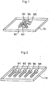
For example, in the case where many (for example, five)
workpieces W1 to W5 (for example, bolts) are piled up disorderly on
a tray TR as shown in Fig. 1, it is not easy to pick up individual
workpieces by a robot even with the aid of a visual sensor.
-
Especially when the holding posture of a robot hand requires a
certain accuracy, for example, when the axial direction of bolt must
be made agree with the Z-axis direction of the tool coordinate
system, this picking-up work is especially difficuft to do.
-
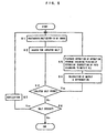
To solve this problem, conventionally in many cases, the
workpieces W1 to W5 are lined up or positioned so as to preclude the
lapping before the picking-up work is performed by the robot as
shown in Fig. 2. If the visual sensor is used, the decreased
accuracy of lining-up or positioning of the workpieces W1 to W5 is
allowed, and in some cases, some lapping of the workpieces is also
allowed.
-
However, to realize the state as shown in Fig. 2 or a state
similar to this state, manual work or a large-scale automatic lining-up/positioning
mechanism is needed, which causes an obstacle to
automating the process by using a simple system. Also, with either
manual work or the use of automatic mechanism, the process time
is liable to be prolonged by the lining-up or positioning.
-
An object of the present invention is to provide an apparatus
capable of picking up articles exactly one by one from many piled-up
articles without a manual operation for lining-up or positioning the
articles and without using any special lining-up/positioning
mechanism.
-
In the present invention, to attain the above object, even in the
case where many articles are piled up, the piled-up articles are
loosened (including the decreasing of the degree of pileup of articles
at least partially and the elimination of the pileup) by directly or
indirectly giving a proper physical action to a group of articles, and
the loosened article can be picked up one by one by a robot.
-
The article picking-up apparatus in accordance with the
present invention comprises a robot; articles placing means;
loosening means having a function of giving a physical action to a
group of articles mounted on said articles placing means in a piled-up
state to loosen the piled-up state; and a visual sensor which
searches for a group of articles on the articles placing means to find
at least one holdable article that can be held by the robot in
accordance with a predetermined criterion, and obtains data
concerning the position of the holdable article. The robot is
operated so as to hold and pick up the holdable article by using the
data concerning the position of the holdable article.
-
As the visual sensor, either a two-dimensional visual sensor or
a three-dimensional visual sensor may be used.
-
As an example of criterion, an isolated article which is not
lapped over any another article is taken as a holdable article. Also,
as another example of criterion, one isolated article or an isolated
small set consisting of a certain number ("N" number) or less
articles contacting with each other is taken to be a set of holdable
articles. The latter criterion is suitable to the picking-up
apparatus using a three-dimensional visual sensor.
-
Here, the aforementioned value of N (for example, five) is
selected as a value such that the robot can pick up individual
articles from the maximum N number of articles with the aid of the
visual sensor even if they are in contact with each other or piled up.
-
A group of articles to be picked up is subjected to a physical
action. This physical action is typically an oscillating motion. As
means for giving the oscillating motion to the articles to loosen or
disentangle the articles, a shaking device attached to the articles
placing means or a robot to which an operation for oscillating the
articles placing means is taught can be used Also, as loosening
means of another type for giving a physical action to a group of
articles, a tool for loosening the piled-up articles is mounted to the
robot. The robot is taught and operated so as to level the pile of a
group of articles by using the tool to establish a state in which the
articles are isolated or a state in which N number or less articles are
in contact with each other.
-
According to the present invention, the lining-up or positioning
of articles, which have conventionally been needed before the
holding and picking-up operation of robot is started, becomes
unnecessary. Therefore, manpower or a special-purpose
mechanism for lining up or positioning the articles can be saved.
As a result, great advantages can be obtained in terms of work
efficiency and economical cost.
BRIEF DESCRIPTION OF THE DRAWINGS
-
The foregoing and other objects and features of the invention
will become apparent from the following description of preferred
embodiments of the invention with reference to the accompanying
drawings, in which:
- Fig. 1 is a perspective view showing a typical state in which
bolts to be picked up are piled up;
- Fig. 2 is a perspective view showing a typical state in which
the bolts shown in Fig. 1 are lined up or positioned;
- Fig. 3 is a schematic view showing a general arrangement of a
system used in a first embodiment of the present invention;
- Fig. 4 is a block diagram showing a somewhat detailed
configuration of the system shown in Fig. 3;
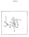
- Fig. 5 is a flowchart showing the outline of picking-up process
in the first embodiment;
- Fig. 6 is a plan view for illustrating the search for an isolated
bolt;
- Fig. 7 is a schematic view showing a general arrangement of a
system used in a second embodiment of the present invention;
- fig. 8 is a block diagram showing a somewhat detailed
configuration of the system shown in Fig. 7;
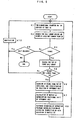
- Fig. 9 is a flowchart showing the outline of picking-up process
in the second embodiments;
- Fig. 10 is a perspective view showing a state in which the top
surface of a tray is scanned two-dimensionally by a spotlight of a
projector;
- Fig. 11 is a view for illustrating the occupied area of bolts;
- Fig. 12 is a view for illustrating the height of the top of a group
of bolts;
- Fig. 13 is a perspective view for illustrating a state in which
the portion around a ridge extending from the top is scanned by a
spotlight and a positional shift of an uppermost bolt;
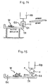
- Fig. 14 is a view for illustrating an oscillating motion given by
a robot; and
- Fig. 15 is a view for illustrating for an operation for loosening
the piled-up articles by using a loosening device supported by the
robot.
-
DETAILED DESCRIPTION OF THE PREFERRED
EMBODIMENTS
[First embodiment]
-
Fig. 3 is a schematic view showing a general arrangement of a
system, which includes an article picking-up apparatus in
accordance with the present invention, used in a first embodiment
of the present invention. In this embodiment, the articles to be
picked up are a large number of bolts. In Fig. 3, five bolts are
shown as an example, and the whole thereof is indicated by a bolt
group W.
-
The bolt group W is supplied by using a supply device (not
shown) in such a manner as to be disorderly piled up on a placing
surface PL of a tray TR. The tray TR is attached to a shaking
device 1 so that a physical action is given to the bolt group W.
When the shaking device 1 is operated, the tray TR is oscillated, so
that the piled-up bolt group W is loosened or disentangled.
-
A CCD camera 4, which has a field of view covering almost the
whole of the tray TR, is provided at an appropriate place just above
the tray TR, and a robot 2 (only the hand portion thereof is shown)
is provided at an appropriate place near the tray TR. The robot 2
is equipped with a hand 3 suitable for holding the individual bolt.
-
An image processing device 10 is connected to the camera 4.
Both of the image processing device 10 and the camera 4 constitute
a publicly known two-dimensional visual sensor. Reference
character MO denotes a monitor display consisting of a liquid
crystal display, a CRT, or the like attached to the image processing
device 10, which can display images obtained by the camera 4 or
images processed by the image processing device 10.
-
Reference numeral 20 denotes a robot controller that is also
used as a controller for the whole system. The robot controller 20
is connected to not only the robot 2 but also to the shaking device 1,
the image processing device 10, and necessary external devices (for
example, a mechanism for supplying the bolt group W to the tray
TR). The following is a rough description of the roles of the
principal elements.
Shaking device 1:
-
The shaking device 1 oscillates the tray TR on command from
the robot controller 20 to give an oscillating motion to the bolt group
W. For the shaking device itself, for example, a type using an
electromagnet and other types are publicly known. Therefore, the
details are omitted.
Two-dimensional visual sensor:
-
- (1) The two-dimensional visual sensor photographs the bolt
group W by using the camera 4 on command from the robot
controller 20 when the shaking device 1 is stopped, and takes the
image in the image processing device 10.
- (2) The image prodessing device 10 analyzes the taken-in
image, and performs "the search for holdable bolt" and "the
detection of position of the found holdable bolt." The result is sent
to the robot controller 20. Here, a "holdable bolt (a holdable article
in general; the same also applies to the following)" means a bolt tha
can be held exactly by the robot 2. The presence of holdable bolts is
judged in accordance with a preset criterion. In this embodiment,
an "isolated bolt" is taken as the holdable bolt, as described later.
-
Robot controller 20:
-
- (1) The robot controller 20 operates the shaking device 1 at a
predetermined time for a fixed period of time (for example, for
several seconds) to give an oscillating motion to the bolt group W, by
which holdable bolts (in this embodiment, isolated bolts) are
produced.
- (2) The robot controller 20 operates the visual sensor (camera 4
and image processing device 10) at a predetermined time to perform
photographing, image accumulation, image processing, etc. Also, it
receives the data representing the success in search of holdable
bolts and the data concerning the positions of the holdable bolts
from the image processing device 10.
- (3) When a holdable bolt exists on the tray TR, the robot
controller 20 starts an operation program (a picking-up operation
has been taught in advance) and operates the robot 2 to pick up an
individual holdable bolt. In the operation program, approach for
picking-up operation, holding, and transfer after holding have been
taught. The teaching may be performed by placing a single bolt
lying in standard posture at a standard position on the tray TR
and by making the robot controller 20 store the picking-up
operation by using a teaching playback system.
-
-
At the time of playback operation for the actual work, the
approach path and holding posture of the robot are corrected on the
basis of the data concerning the position (including posture; the
same also applies to the following) of a holdable bolt (in this
embodiment, an isolated bolt; the details are described later) output
from the visual sensor.
-
Fig. 4 is a block diagram showing a somewhat detailed
configuration of the above-described system. Referring to Fig. 4,
the image processing device 10 has a central processing unit
(hereinafter referred to as a CPU) 11. The CPU 11 connects with a
frame memory (image memory) 12, a control software memory 13
configurated by a ROM, a program memory 14 configured by a RAM
etc., a data memory 15 configured by nonvolatile RAM, a camera
interface 16, an image processing processor 17, a communication
interface 18, and a monitor interface 19 via a bus BS1.
-
The communication interface 18 is connected to a
communication interface 27 at the side of the robot controller 20,
and signals representing data and commands are transferred via
both of these interfaces. Also, the camera 4 is connected to the
camera interface 16. Further, the monitor MO is connected to the
monitor interface 19, so that the image captured by the camera 4,
the image invoked from the frame memory 12, and the processed
image (for example, a contour extract image) can be seen at an
appropriate time.
-
The image captured by the field of view of the camera 4 is
converted into a variable density image by grey scale and stored in
the frame memory 12. The image processing processor 17 has a
function of processing the image stored in the frame memory 12 on
command of the
CPU 11. The
control software memory 13 stores
the following programs and related parameters:
- (1) A control program for the CPU 11 to control the visual
sensor.
- (2) A calibration program for setting a sensor coordinate
system by using a jig.
- (3) An image analyzing program for executing "the search for
isolated bolt" and "the detection of position of the isolated bolt, "
described later, by using the image processing processor 17.
- (4) A program for sending and receiving data to and from the
robot at appropriate timing.
-
-
The image captured by the camera 4, the image invoked from
the frame memory 12, and the processed image (for example, a
contour extract image) can be seen on a display screen of the
monitor MO at an appropriate time.
-
On the other hand, the robot controller 20 has a central
processing unit (CPU) 21. The CPU 21 connects with a ROM 22 for
storing various control programs including a program for executing
the processing for a picking-up operation, described later, a RAM 23
used for the temporary storage of calculation data etc., a nonvolatile
memory 24 for storing teaching data and various parameters, a
digital servo circuit 25 for controlling the individual axes of the
robot body 2, a teaching panel 26 for performing manual operation,
setting of coordinate system, position teaching, automatic operation
(playback operation), etc. of the robot, and a general purpose signal
interface 27 connected to the communication interface 18 at the side
of the image processing device 10 via a bus BS2.
-
Next, the outline of process for executing the picking-up
operation by using the above-described system will be described
with reference to a flowchart shown in Fig. 5. The point of each
step shown in Fig. 5 is as described below. In this process, it is
assumed that the calibration of the visual sensor, and the teaching
of approach, holding, transfer after holding, etc. for the picking-up
operation have been finished.
-
Step S1: The bolt group W is photographed by the camera 4
on command from the robot controller 20, and the image is taken in
the image processing device 10.
-
Step S2: The taken-in image is analyzed, and an isolated bolt
is searched for as a holdable bolt . Here, the "isolated bolt" means a
bolt such that the contour of one bolt is isolated (not lapped) from
other bolt images on the screen as indicated by reference character
A or B in Fig. 6. As an image "processing software for searching for
an isolated bolt, the publicly known pattern matching method is
available.
-
According to this method, a standard pattern (here, a bolt
contour image) representing the shape and size of an article to be
searched for is stored in the image processing device 10 in advance,
and the contour image element captured actually is compared with
the standard pattern. In this example, the contour image elements
A, B and C are compared with the standard pattern in succession.
The contour image elements A and B are apparently capable of
being lapped on the standard pattern (in other words, they can be
matched with each other), so that they are judged to be the images
of isolated bolts. The contour image element C is apparently
incapable of being lapped on the standard pattern (in other words,
they cannot be matched with each other), so that it is judged not to
be the image of isolated bolt.
-
Step S3: If at least one isolated bolt is found by the search of
isolated bolt, the process proceeds to Step 54. If none is found, the
process proceeds to Step S5. For example, in the case shown in Fig.
6, the process proceeds to Step S4.
-
Step S4: The position of the found isolated bolt is detected,
and a deviation from a standard position in teaching (indicated by
vector T) is determined. For example, in the case shown in Fig. 6,
taking the image of a first found isolated bolt as A, a matrix ΔA
(homogeneous transformation matrix of four lines and four rows)
representing the relationship between vector A and vector T is
determined. The matrix ΔA is calculated assuming that vector A
and vector T lie on a fixed plane (XY plane: Z = 0) and the Z
component of vector T is zero. The rotation component of matrix
ΔA represents the rotation on the XY plane, and the translation
component thereof represents the translation on the XY plane.
-
Step S5: The operation program having been taught in
advance is started, and the robot 2 is operated to pick up isolated
bolt A. At this time, the approach path and holding posture of
robot are corrected in accordance with the data of matrix ΔA. After
the operation is finished, the process returns to Step S1.
Subsequently, steps S2 and S3 are executed again. If an isolated
bolt remains, the process further proceeds from Step S3 to Step S4.
In the case shown in Fig. 6, a matrix ΔB representing the
relationship between vector B and vector T is determined this time.
-
Step S6: In the case where no isolated bolt is found, two
situations are assumed. That is to say, if a bolt image is present,
but no isolated bolt is found (two or more bolts remain), the process
proceeds to Step 57. If a bolt image itself is absent, the process is
finished because this state means that all bolts have been picked up.
-
Step S7: The shaking device 1 is operated for a fixed period of
time to give an oscillating motion to the bolt group remaining on the
tray TR at this point of time. After the operation of the shaking
device 1 is stopped, the process returns to Step S1. In many cases,
by the oscillating motion, some or all of the piled-up bolts are
separated, and one or more isolated bolts are produced newly.
-
If an isolated bolt is produced newly, the processing cycle of
Step S1 → Step S2 → Step S3 → Step S4 → Step S5 → Step S1 is
executed. If the oscillating motion is insufficient and therefore no
isolated bolt is produced newly, the process proceeds from Step S1 to
Step S2 to Step S3 to Step S6 to Step S7, and the shaking device 1 is
operated for a fixed period of time again, by which an oscillating
motion is given. After the operation of the shaking device 1 is
stopped, the process returns to Step S1. Subsequently, this cycle is
repeated until the judgment result in Step S3 becomes Yes.
-
By carrying out the aforementioned process, isolated bolts are
picked up one after another. When all bolts have been picked up,
the judgment result in Step S6 is No, and the process is finished.
[Second embodiment]
-
In a second embodiment, a three-dimensional visual sensor is
used in place of the two-dimensional visual sensor. Also, here is
described an example in which a spotlight scanning type projector
incorporating a spotlight projector capable of random scanning and
a PSD position sensitive light detector) 50 is used as the three-dimensional
visual sensor. The three-dimensional visual sensor of
any one type, for example, a slit light projector type three-dimensional
visual sensor incorporating a slit light projector and a
CCD camera may be used. Further, as a criterion for searching for
a holdable bolt, a criterion different from that of the first
embodiment (the details are described later) is used.
-
Fig. 7 is a schematic view showing a general arrangement of
another system to which an article picking-up apparatus and
method in accordance with the present invention are applied as the
second embodiment of the present invention. In this embodiment
as well, the articles to be picked up are a large number of bolts. In
Fig. 7, five bolts are shown as an example, and the whole thereof is
indicated by a bolt group W.
-
As in the case of the first embodiment, the bolt group W is
supplied by using a supply device (not shown) in such a manner as
to be disorderly piled up on a placing surface PL of a tray TR. The
tray TR is attached to a shaking device 1 so that an oscillating
motion is given to the bolt group W. A robot 2 (only the hand
portion thereof is shown) is provided at an appropriate place near
the tray TR, and a projector 40 which covers almost the whole of the
tray TR as a scannable region and a PSD 50 equipped with a lens
system LS are disposed at appropriate places around the tray TR.
The projector 40 is made up of a laser beam source 41, deflectors 42
and 43 in which two rotating deflection axes intersect at right
angles, and mirrors MX and MY attached to the deflectors 42 and 43,
respectively.
-
The driving control of the projector 40 and the processing of
output signals of the PSD 50 are carried out by a projector
driving/signal processing device 60. The projector 40, PSD 50, and
projector driving/signal processing device 60, together with a part
(software and hardware for searching for a holdable bolt in
accordance with the criterion) of robot controller 30, constitute the
publicly known three-dimensional visual sensor.
-
As in case of the first embodiment, the robot 2 is equipped with
a hand 3 suitable for holding the individual bolt. Reference
numeral 30 denotes a robot controller which is also used as a
controller for the whole system. The robot controller 30 is
connected not only to the robot 2 but also to a shaking device 1, the
projector driving/signal processing device 60, and necessary
external devices (for example, a mechanism for supplying the bolt
group W to the tray TR). The following is a rough description of
the roles of the principal elements.
Shaking device 1:
-
The shaking device 1 is the same as that of the first
embodiment. It oscillates the tray TR on command from the robot
controller 30 to give an oscillating motion to the bolt group W.
Three-dimensional visual sensor:
-
- (1) The projector driving/signal processing device 60, receiving
a command from the robot controller 30 when the shaking device 1
is stopped, scans the bolt group W with a spot beam L1 projected
from the projector 40, and carries out detection with the PSD 50 via
the lens system LS. The data detected by the PSD 50 is processed
by the projector driving/signal processing device 60, and the data
concerning three-dimensional position for the bolt group W is
collected. The collected data is sent to the robot controller 30.
- (2) The spotlight projection type three-dimensional visual
sensor itself is publicly known (for example, see Japanese Patent
Application Laid-Open No. 6-229732 and Japanese Patent
Application Laid-Open No. 7-270137). Therefore, the detailed
description thereof is omitted, and only the measurement principle
is briefly described. The deflectors 42, 43 control the directions of
the mirrors MX and MY according to a set of voltage commands (Vx,
Vy) issued from the projector driving/signal processing device 60.
-
-
Therefore, if the relationship between the voltage commands
(Vx, Vy) and the position (equation of straight line) of the spot beam
L1 is determined in advance by calibration, the spot beam L1 can
perform scanning in a desired pattern by programming the timerelated
change pattern of the voltage commands (Vx, Vy).
-
The spot beam L1 incident on a certain incident position P at
any point of time produces a luminescent spot. This luminescent
spot is detected by point Q on the light intercepting face of the PSD
50 via the lens system LS. The PSD 50 may be of a one-dimensional
type. As the direct output of the PSD 50, two currents
il and i2 according to the one-dimensional position of point Q are
output. They pass through a publicly known analog signal
processing circuit, and are converted into an output signal Vq
representing the one-dimensional position of point Q.
-
The three-dimensional position of the incident position P is
determined by solving, as simultaneous equations, the equation of
straight line representing the spot beam L1 specified by (Vx, Vy)
and the conditional expression that gives the output signal Vq for
point Q. Actually, the relational expression P(x, y, z) = f(Vx, Vy,
Vq) approximately representing the general solution of the above
simultaneous equations is stored in advance in the projector
driving/signal processing device 60 or the robot controller 30, by
which the three-dimensional position of point P can be detected at
any time.
Robot controller 30:
-
- (1) The robot controller 30 operates the shaking device 1 at a
predetermined time for a fixed period of time (for example, for
several seconds) to give an oscillating motion to the bolt group W, by
which holdable bolts are produced. The definition (criterion) of the
holdable bolt differs from that in the first embodiment, as described
later.
- (2) The robot controller 30 operates the spotlight scanning type
three-dimensional visual sensor at a predetermined time to obtain
the data concerning the three-dimensional position for the bolt
group W.
- (3) As in case of the first embodiment, when a holdable bolt is
present on the tray TR, the robot controller 30 starts an operation
program (for which a picking-up operation has been taught in
advance) and operates the robot 2 to pick up an individual holdable
bolt.
-
-
In the operation program, approach for picking-up operation,
holding, and transfer after holding have been taught. The
teaching may be performed by placing a single bolt lying in a
standard posture at a standard position on the tray TR and by
making the robot controller 20 store the picking-up operation by
using a teaching playback system.
-
At the time of playback operation for the actual work, the
approach path and holding posture of the robot are corrected on the
basis of the data concerning the position of a holdable bolt (the
details are described later) output from the three-dimensional
visual sensor.
-
Fig. 8 is block diagram showing a somewhat detailed
configuration of the system in the second embodiment. Referring
to Fig. 8, the robot controller 30 has a CPU 31. The CPU 31
connects with a ROM 32 for storing various control programs, a
RAM 33 used for the temporary storage of calculation data etc., a
nonvolatile memory 34 for storing taught data and various
parameters, a digital servo circuit 35 for controlling the individual
axes of the robot body 2, a teaching panel 36 for performing manual
operation, setting of coordinate system, position teaching, automatic
operation (playback operation), etc. of the robot, and an input-output
device (I/O) 37 via a bus BS. In particular, in this
embodiment, the control program includes programs for executing
the search for a holdable bolt, the detection of position of the
holdable bolt, and the picking-up operation of the holdable bolt by
means of the robot 2 (the details of processing will be described
later).
-
The input-output device (1/O) 37 is connected to a projector
driving section 61 and a PSD detection signal processing section 62
of the projector driving/signal processing device 60. The projector
driving section 61 and the PSD detection signal processing section
62 each have a required CPU, memories, input-output device, and
the like. The former is connected to the projector 40 to control the
driving of the laser beam source 41 and the deflectors
(galvanometers) 42 and 43, and the latter processes the output
signals of the PSD 50, and sends signal Vq representing the position
of detection point Q to the robot controller 30. The processing such
as the acquisition of three-dimensional position data based on the
voltage commands Vx, Vy, Vq and the subsequent search for a
holdable bolt is performed in the robot controller 30.
-
Next, the outline of process for executing the picking-up
operation by using the above-described system will be described
with reference to a flowchart shown in Fig. 9. The point of each
step shown in Fig. 9 is as described below. In this process, it is
assumed that the calibration of the visual sensor, and the teaching
of approach, holding, transfer after holding, etc. for the picking-up
operation have been finished. Also, as a world coordinate system
representing the three-dimensional position, a coordinate system in
which a placing surface PL of the tray TR is taken as the XY plane
(Z=0), and the vertical upward direction is taken as +Z axis
direction is set in the system (robot controller 30).
-
Step K1: As shown in Fig. 10, the top surface of the tray TR is
scanned two-dimensionally by the projector 40, and the three-dimensional
position data concerning the incident point P of
spotlight is collected. If Z≻0, it is found that the incident point P of
spotlight lies on a bolt. If Z=0, it is found that the incident point P
of spotlight lies on the placing surface PL (where any bolt is absent)
of the tray TR.
-
Step K2: As a first step for searching for an isolated small set
including holdable bolts, as shown in Fig. 11, a bolt group such that
the occupied area (area surrounded by reference characters a,b,c,...
s,t,u) is not larger than the reference value 3S is searched for.
Here, S is a reference value approximately representing an area
occupied by a single bolt, and it is preferable that the optimum
value be finely adjusted by tuning, the rule of thumb, etc. Generally,
if Sis set to be smallish, a set consisting of four or more bolts can
easily be excluded (that is, it is not judged to be an isolated small
set).
-
Step K3: If at least one bolt group having an occupied area
not larger than 3S is found in Step K2, the process proceeds to Step
K4. If none is found, the process proceeds to Step K9.
-
Step K4: Atop (a point that gives the maximum Z-axis value)
of the bolt groups is searched for based on the three-dimensional
position data concerning the found bolt group.
-
Step K5: As shown in Fig. 12, if the top height is not larger
than the reference value 3d, it is judged to be an isolated small set
including holdable bolts, and the process proceeds to Step K6. If
the top height exceeds the reference value 3d, it is judged that the
bolt group consists of bolts piled up over and over again and is not a
small bolt group including holdable bolts, and the process proceeds
to Step K10.
-
Here, as additionally shown in Fig. 12, "d" is a reference value
approximately representing a diameter (a height when the bolt is
placed horizontally) of a single bolt, and it is preferable that the
optimum value be finely adjusted by tuning, the rule of thumb, etc.
Generally, if d is set to be smallish, a set consisting of four or more
bolts can easily be excluded.
-
As explained above, the criterion in this embodiment is used
for searching for an "isolated small set" from both of the viewpoints
of occupied area and top height.
-
Step K6: As shown in Fig. 13, a ridge extending from the top
is scanned by a spotlight, and the position data concerning the ridge
is collected. Then, vector H representing the position of an
uppermost bolt H is determined Generally, the Z component of
vector H is not zero.
-
Step K7: A matrix ΔH (homogeneous transformation matrix
of four lines and four rows) representing a deviation of vector H5
from a standard position (indicated by vector T) at the time of
teaching is determined. It is to be noted that vector T lies on the
XY plane, but vector H does not lie on the XY plane. The rotation
component of matrix ΔH represents the rotation in the three-dimensional
space, and the translation component thereof
represents the translation in the three-dimensional space.
-
Step K8: The operation program having been taught in
advance is started, and the robot 2 is operated to pick up uppermost
bolt H. At this time, the approach path and holding posture of
robot are corrected in accordance with the data of matrix ΔH. After
the operation is finished, the process returns to Step K1.
-
Subsequently, steps S2 and the subsequent steps are executed
again. If an isolated small set remains, Step K8 is reached again,
and the next bolt (for example, bolt I in Fig. 13) is picked up.
-
Step K9: As a case where the judgment result in Step K3 is
No, two situations are assumed. That is to say, if the bolt image is
present but no isolated small set is found (several or more bolts
remain), the process proceeds to Step K10. If the bolt image itself
is absent, the process is finished because this state means that all
bolts have been picked up.
-
Step 10: The shaking device 1 is operated for a fixed period of
time to give an oscillating motion to the bolt group remaining on the
tray TR at this point of time. After the operation of the shaking
device 1 is stopped, the process returns to Step K1. In many cases,
by the oscillating motion, some or all of the piled-up bolts are
separated, and one or more isolated bolts are produced newly.
-
If an isolated small set is produced newly, the processing cycle
of Step K1 → Step K2 → ... → Step K8 → Step K1 is executed. If
the oscillating motion is insufficient and therefore no isolated small
set is produced newly, the shaking device 1 is operated for a fixed
period of time again through Step K2 → Step K3 → Step K9 or Step
K2 → ... → Step K5, by which an oscillating motion is given. After
the operation of the shaking device 1 is stopped, the process returns
to Step K1. Subsequently, this cycle is repeated until the judgment
results in Step K3 and Step K5 become Yes.
-
By carrying out the aforementioned process, bolts are picked
up one after another. When all bolts have been picked up, the
judgment result in Step K9 is No, and the process is finished.
-
In the above two embodiments, the physical action applied to a
group of articles to loosen the piled-up articles is an oscillating
motion, and this oscillation motion is produced by the shaking
device attached to the tray TR. However, the present invention is
not limited to these examples.
-
For example, the physical action may be applied by a robot RB
(which may be the same as or separated from a robot for holding the
article). In this case, as shown in Fig. 14, the tray TR is supported
elastically, and the approach operation to the edge of the tray TR,
the operation for holding the edge of the tray TR by means of a hand
H, the oscillating operation (for example, the reciprocating motion
between G1 and G2) with the tray TR being held, the retreat
operation, etc. are taught to the robot RB in advance.
-
Also, as shown in Fig. 15, the robot RB may be equipped with a
loosening member F such as a leveling plate or a brush-like leveling
member to loosen the piled-up article group by using the loosening
member F. In this case, an operation suitable for loosening the
piled-up article group (for example, the reciprocating motion
between G3 and G4) is taught to the robot RB.
-
Further, as shown in Figs. 3 and 7, an air gun AG may be
provided near the tray TR to loosen the piled-up article group W by
an air jet or jet of (or jet of any other gas) blown from the air gun AG.
The broken line 100 in the figures indicates a cable 100 connecting
the air gun AG to the robot controller 20 or 30 when the air gun AG
is used. The air gun AG is operated on command from the robot
controller 20 or 30. It may be used together with the shaking
device 1 (switching operation, simultaneous operation, etc.) or may
be used as a means for loosening substituting for the shaking device
1.