EP0949502A2 - Device for detecting a fluorescent dye - Google Patents
Device for detecting a fluorescent dye Download PDFInfo
- Publication number
- EP0949502A2 EP0949502A2 EP98123363A EP98123363A EP0949502A2 EP 0949502 A2 EP0949502 A2 EP 0949502A2 EP 98123363 A EP98123363 A EP 98123363A EP 98123363 A EP98123363 A EP 98123363A EP 0949502 A2 EP0949502 A2 EP 0949502A2
- Authority
- EP
- European Patent Office
- Prior art keywords
- detected
- light
- fluorescent dye
- fluorescent
- glass plate
- Prior art date
- Legal status (The legal status is an assumption and is not a legal conclusion. Google has not performed a legal analysis and makes no representation as to the accuracy of the status listed.)
- Withdrawn
Links
- 0 C*1CCCC1 Chemical compound C*1CCCC1 0.000 description 1
Images


Classifications
-
- G—PHYSICS
- G01—MEASURING; TESTING
- G01N—INVESTIGATING OR ANALYSING MATERIALS BY DETERMINING THEIR CHEMICAL OR PHYSICAL PROPERTIES
- G01N21/00—Investigating or analysing materials by the use of optical means, i.e. using sub-millimetre waves, infrared, visible or ultraviolet light
- G01N21/62—Systems in which the material investigated is excited whereby it emits light or causes a change in wavelength of the incident light
- G01N21/63—Systems in which the material investigated is excited whereby it emits light or causes a change in wavelength of the incident light optically excited
- G01N21/64—Fluorescence; Phosphorescence
- G01N21/645—Specially adapted constructive features of fluorimeters
- G01N21/648—Specially adapted constructive features of fluorimeters using evanescent coupling or surface plasmon coupling for the excitation of fluorescence
-
- G—PHYSICS
- G01—MEASURING; TESTING
- G01N—INVESTIGATING OR ANALYSING MATERIALS BY DETERMINING THEIR CHEMICAL OR PHYSICAL PROPERTIES
- G01N2201/00—Features of devices classified in G01N21/00
- G01N2201/06—Illumination; Optics
- G01N2201/065—Integrating spheres
Abstract
Description
Die Erfindung betrifft eine Vorrichtung zum Nachweis eines Fluoreszenzfarbstoffs in einer Probe mit einer Einrichtung zum Anregen des nachzuweisenden Fluoreszenzfarbstoffs, die eine Lichteinkopplungseinrichtung, durch welche Licht zum Anregen des Fluoreszenzfarbstoffs in die Einrichtung einkoppelbar ist, und eine zum Aufbringen der Probe vorgesehene Oberfläche aufweist, und mit einer Einrichtung zum Detektieren von Fluoreszenzstrahlung, die durch den nachzuweisendes Fluoreszenzfarbstoff emittiert worden ist.The invention relates to a device for detecting a fluorescent dye in a sample with a device for exciting the fluorescent dye to be detected, the one light coupling device through which light to excite of the fluorescent dye can be coupled into the device, and one for application of the sample provided surface, and with a device for detection of fluorescent radiation caused by the fluorescent dye to be detected has been issued.
Eine derartige Vorrichtung ist aus dem Artikel "A Planar Indium Phosphate Monomode Waveguide Evanescent Field Immunosensor" von A.N. Sloper, J.K. Deacon und M.T. Flanagan, in Sensors and Actuators, B1(1990), Seiten 589-591, bekannt.Such a device is from the article "A Planar Indium Phosphate Monomode Waveguide Evanescent Field Immunosensor "by A.N. Sloper, J.K. Deacon and M.T. Flanagan, in Sensors and Actuators, B1 (1990), pages 589-591.
Insbesondere ist in diesem Artikel eine erste Ausführungsform offenbart, in welcher ein Dünnfilm-Wellenleiter auf einem Glassubstrat vorgesehen ist. Durch eine Lichteinkopplungseinrichtung wird monochromatisches Laserlicht in den Dünnfilm-Wellenleiter so eingekoppelt, daß es parallel zur Oberfläche des Dünnfilm-Wellenleiters durch denselben geleitet wird. Fluoreszenzfarbstoff, der in einer auf dem Wellenleiter aufgebrachten Probe enthalten ist, wird durch das evaneszente Feld der sich entlang des Dünnfilm-Wellenleiters bewegenden Laserstrahlung angeregt. Die durch die Abregung des Fluoreszenzfarbstoff emittierte Fluoreszenzstrahlung wird schließlich mit einer Photomultipliereinrichtung nachgewiesen.In particular, this article discloses a first embodiment in which a thin film waveguide is provided on a glass substrate. Through a light coupling device becomes monochromatic laser light in the thin film waveguide so coupled that it passes parallel to the surface of the thin film waveguide the same is directed. Fluorescent dye applied in a on the waveguide Sample is contained by the evanescent field located along the Thin film waveguide excited laser radiation. That through the depletion of the fluorescent dye is finally emitted with a Detected photomultiplier.
Weiterhin offenbart dieser Artikel eine zweite Ausführungsform der oben beschriebenen Vorrichtung, in welcher die Einrichtung zum Anregen des nachzuweisenden Fluoreszenzfarbstoffs in Form einer Glasplatte mit einer Lichteinkopplungseinrichtung vorgesehen ist, wobei monochromatisches Laserlicht durch die Lichteinkopplungseinrichtung so in die Glasplatte eingekoppelt wird, daß es unter Totalreflexion durch die Glasplatte geleitet wird. Furthermore, this article discloses a second embodiment of the one described above Device in which the device for exciting the fluorescent dye to be detected provided in the form of a glass plate with a light coupling device is, wherein monochromatic laser light through the light coupling device is coupled into the glass plate so that it is totally reflected by the Glass plate is passed.
Wie im Fall des Dünnfilm-Wellenleiters wird auch in dieser Ausführungsform ein Fluoreszenzfarbstoff, der in einer auf der Glasplatte aufgebrachten Probe enthalten ist, durch das evaneszente Feld der Laserstrahlung angeregt. Die aus dieser Anregung resultierende Fluoreszenzstrahlung wird schließlich wiederum durch eine Photomultipliereinrichtung nachgewiesen.As in the case of the thin film waveguide, a fluorescent dye, contained in a sample placed on the glass plate, excited by the evanescent field of laser radiation. The one from this suggestion the resulting fluorescence radiation is in turn passed through a photomultiplier device proven.
Ein Nachteil beider aus dem Stand der Technik bekannter Ausführungsformen liegt allerdings darin, daß die Fluoreszenzstrahlung, die keine Vorzugsrichtung aufweist und daher in den gesamten Raumwinkel abgestrahlt wird, nur aus einem kleinen Raumwinkelbereich nachgewiesen werden kann. Folglich zeigen die bekannten Vorrichtungen nur eine sehr kleine Nachweiswahrscheinlichkeit.A disadvantage of both embodiments known from the prior art lies however, in that the fluorescent radiation, which has no preferred direction and is therefore emitted in the entire solid angle, only from a small one Solid angle range can be demonstrated. Consequently, the known devices show only a very small probability of detection.
Angesichts dieses Nachteils der Vorrichtungen gemäß dem Stand der Technik liegt der Erfindung die Aufgabe zugrunde, die bekannte Vorrichtung zum Nachweis eines Fluoreszenzfarbstoffs dahingehend zu verbessern, daß ihre Nachweiswahrscheinlichkeit erhöht wird.In view of this disadvantage of the prior art devices the invention has for its object the known device for detecting a Fluorescent dye to improve the probability of detection is increased.
Diese Aufgabe wird durch eine Vorrichtung der eingangs genannten Art gelöst, die sich auszeichnet durch einen Hohlraum, der eine hochreflektive innere Oberfläche, eine erste, der Einrichtung zum Anregen des nachzuweisenden Fluoreszenzfarbstoffs gegenüberliegende Öffnung und eine zweite, der Einrichtung zum Detektieren gegenüberliegende Öffnung aufweist.This object is achieved by a device of the type mentioned at the outset is characterized by a cavity that has a highly reflective inner surface, a first, the device for exciting the fluorescent dye to be detected opposite opening and a second, opposite the device for detection Has opening.
Dadurch, daß die Einrichtung zum Anregen des nachzuweisenden Fluoreszenzfarbstoffs, auf deren Oberfläche die Probe aufgebracht ist, der ersten Öffnung des Hohlraums gegenüberliegt, wird nahezu die Hälfte der emittierten Fluoreszenzstrahlung in den Hohlraum eingestrahlt. Da der Hohlraum weiterhin eine hochreflektive innere Oberfläche aufweist, kann die in den Hohlraum eingestrahlte Strahlung dort nahezu verlustfrei ausbreiten, bis sie von einem Detektor nachgewiesen wird.The fact that the device for exciting the fluorescent dye to be detected, on the surface of which the sample is applied, the first opening of the cavity is almost half of the emitted fluorescence radiation in irradiated the cavity. Because the cavity continues to be a highly reflective interior Has surface, the radiation radiated into the cavity can be almost there Spread without loss until it is detected by a detector.
Demnach ist es möglich, die Fluoreszenzstrahlung aus einem Raumwinkel von nahezu 2π Steradien nachzuweisen, wodurch die Nachweisempfindlichkeit der Vorrichtung gegenüber den bekannten Vorrichtungen stark erhöht wird. Accordingly, it is possible to get the fluorescence radiation from a solid angle of almost Detect 2π steradiene, reducing the detection sensitivity of the device is greatly increased compared to the known devices.
Gemäß einer bevorzugten Ausgestaltung der Erfindung umfaßt die hochreflektive Oberfläche Bariumsulfat oder Spektralon. Derartige Oberflächen weisen eine Reflektivität von bis zu 99,8 % auf. Demnach können die Reflexionsverluste in dem Hohlraum sehr klein gehalten werden.According to a preferred embodiment of the invention, the highly reflective Surface barium sulfate or spectral. Such surfaces have a reflectivity up to 99.8%. Accordingly, the reflection losses in the cavity be kept very small.
Gemäß einer weiteren bevorzugten Ausgestaltung der vorliegenden Erfindung können weitere Einrichtungen zum Detektieren in entsprechenden, jeder weiteren Einrichtung zum Detektieren gegenüberliegenden Öffnungen in dem Hohlraum vorgesehen sein.According to a further preferred embodiment of the present invention further devices for detection in corresponding, each further device provided for detecting opposite openings in the cavity be.
Demnach ist eine simultane Erfassung von Signalen mittels mehrerer Detektoren möglich.Accordingly, a simultaneous acquisition of signals by means of several detectors possible.
Diese weiteren Einrichtungen können zum Detektieren von Fluoreszenzstrahlung vorgesehen werden, die von verschiedenen Anregungsniveaus des nachzuweisenden Fluoreszenzfarbstoffs resultieren und demnach verschiedene Wellenlängen aufweisen.These further devices can be provided for detecting fluorescence radiation are to be demonstrated by different excitation levels of the Fluorescent dye result and therefore have different wavelengths.
Somit gestattet diese Anordnung die Messung eines Farbstoffs bei einer Anregungswellenlänge, aber gleichzeitig bei verschiedenen Wellenlängen der Fluoreszenzstrahlung. Da derartige gleichzeitige Messungen der Fluoreszenzstrahlung bei verschiedenen Wellenlängen mit den bekannten Vorrichtungen nicht möglich sind, kann gemäß der Erfindung die Zeit zur Durchführung der Messung der Fluoreszenzstrahlung mit verschiedenen Wellenlängen um einen Faktor N verringert werden, wenn N die Anzahl der verschiedenen Wellenlängen der Fluoreszenzstrahlung bezeichnet.Thus this arrangement allows the measurement of a dye at an excitation wavelength, but at the same time at different wavelengths of fluorescent radiation. Because such simultaneous measurements of fluorescence radiation at different Wavelengths are not possible with the known devices, according to the invention the time to carry out the measurement of the fluorescent radiation different wavelengths can be reduced by a factor of N if N is the number of the different wavelengths of fluorescence radiation.
Weiterhin können gemäß dieser bevorzugten Weiterbildung die weiteren Einrichtungen zum Detektieren zum gleichzeitigen Nachweis weiterer Fluoreszenzfarbstoffe verwendet werden.Furthermore, according to this preferred development, the other facilities for detection for the simultaneous detection of further fluorescent dyes be used.
Demnach ist es möglich, mit verschiedenen Anregungswellenlängen die Fluoreszenzstrahlung verschiedener Fluoreszenzfarbstoffe gleichzeitig zu messen. Ebenso wie in der Anordnung zur Messung der Fluoreszenzstrahlung bei verschiedenen Wellenlängen eines Fluoreszenzfarbstoffs ergibt sich auch in dem Fall der Messung mehrerer Fluoreszenzfarbstoffe eine Verringerung der Meßzeit mit einem Faktor N, wenn mit N die Anzahl der gleichzeitig nachzuweisenden Fluoreszenzfarbstoffe bezeichnet ist.Accordingly, it is possible to use different excitation wavelengths to emit the fluorescent radiation to measure different fluorescent dyes simultaneously. As well as in the arrangement for measuring the fluorescence radiation at different Wavelengths of a fluorescent dye also result in the case of the measurement several fluorescent dyes a reduction in the measuring time with a factor N, if N denotes the number of fluorescent dyes to be detected at the same time is.
Gemäß einer weiteren bevorzugten Ausbildung ist eine Kombination der beiden oben bezeichneten Messungen möglich. Demnach kann die Fluoreszenzstrahlung mehrerer Fluoreszenzfarbstoffe bei jeweils verschiedenen Wellenlängen nachgewiesen werden.According to a further preferred embodiment, a combination of the two is above designated measurements possible. Accordingly, the fluorescent radiation can be several Fluorescent dyes detected at different wavelengths become.
Gemäß einer weiteren bevorzugten Ausgestaltung sind die Einrichtungen zum Detektieren lichtdicht in ihren entsprechenden Öffnungen in dem Hohlraum vorgesehen.According to a further preferred embodiment, the devices for detection are provided light-tight in their corresponding openings in the cavity.
Hierdurch kann vermieden werden, daß Fremdlicht in den Hohlraum eintritt.In this way it can be avoided that extraneous light enters the cavity.
Gemäß einer bevorzugten Weiterbildung kann jede Einrichtung zum Detektieren eine Photomultipliereinrichtung aufweisen.According to a preferred development, each device for detecting one Have photomultiplier.
Weiterhin kann jede Einrichtung zum Detektieren eine Farbfiltereinrichtung umfassen, die auf die Wellenlänge der von ihr nachzuweisenden Fluoreszenzstrahlung abgestimmt ist.Furthermore, each device for detection can comprise a color filter device, which are tuned to the wavelength of the fluorescence radiation to be detected is.
Bei Bedarf kann jede Einrichtung zum Detektieren mit einer Kollimationsoptik versehen werden.If required, each device for detection can be provided with collimation optics become.
Gemäß einer weiteren bevorzugten Ausbildung kann vor der ersten Öffnung des Hohlraums eine Sperrfiltereinrichtung vorgesehen werden, die das zur Anregung verwendete Licht sperrt und die zu detektierende Fluoreszenzstrahlung hindurchläßt. Durch diese Maßnahme kann vermieden werden, daß das zur Anregung verwendete Laserlicht, beispielsweise durch die unvermeidliche Mikrorauhigkeit der Glasoberfläche, in den Hohlraum gestreut wird und dort die Detektion der Fluoreszenzstrahlung ungünstig überlagert. According to a further preferred embodiment, before the first opening of the A blocking filter device can be provided in the cavity, which device is used for excitation Blocks light and allows the fluorescence radiation to be detected to pass through. This measure can be used to avoid using the excitation Laser light, for example due to the inevitable micro-roughness of the glass surface, is scattered into the cavity and there the detection of the fluorescent radiation unfavorably overlaid.
Vorteilhafterweise kann eine derartige Sperrfiltereinrichtung durch ein im Stand der Technik bekanntes Interferenzfilter realisiert werden.Advantageously, such a notch filter device can be replaced by a state of the art Technology known interference filter can be realized.
Dieses Filter kann gemäß einer bevorzugten Ausgestaltung gegenüber der Einrichtung zum Anregen des nachzuweisenden Fluoreszenzfarbstoffs geneigt sein.According to a preferred embodiment, this filter can be compared to the device be inclined to excite the fluorescent dye to be detected.
Hierdurch kann vermieden werden, daß gesperrtes Laserlicht auf die Probe zurückreflektiert wird.This can prevent blocked laser light from reflecting back onto the sample becomes.
Gemäß einer weiteren bevorzugten Ausgestaltung kann die Einrichtung zum Anregen des nachzuweisenden Fluoreszenzfarbstoffs bzw. nachzuweisenden Fluoreszenzfarbstoffe in Form einer Glasplatte, die insbesondere einen relativ hohen Brechungsindex, insbesondere von n >1,46 aufweist, wie beispielsweise Pyrexglas oder synthetischer Quarz, vorgesehen werden.According to a further preferred embodiment, the device for excitation of the fluorescent dye or fluorescent dyes to be detected in the form of a glass plate, which in particular has a relatively high refractive index, in particular of n> 1.46, such as pyrex glass or synthetic Quartz.
Wenn in diesem Fall die Lichteinkopplungseinrichtung in Form eines optisch dicht auf der Glasplatte aufliegenden Prismas oder in Form eines Gitterkopplers vorgesehen ist, kann durch die Lichtkopplungseinrichtung das Licht zur Anregung des Fluoreszenzfarbstoffs bzw. der Fluoreszenzfarbstoffe so in die Glasplatte eingekoppelt werden, daß es unter Totalreflexion durch die Glasplatte geleitet wird.If in this case the light coupling device in the form of an optically tight provided on the glass plate prism or in the form of a grating coupler is through the light coupling device, the light for exciting the fluorescent dye or the fluorescent dyes are so coupled into the glass plate, that it is passed through the glass plate with total reflection.
Gemäß einer alternativen Weiterbildung kann die Einrichtung zum Anregen des nachzuweisenden Fluoreszenzfarbstoffs bzw. nachzuweisenden Fluoreszenzfarbstoffe in Form eines Dünnfilm-Wellenleiters ausgebildet sein.According to an alternative development, the device for exciting the fluorescent dye to be detected or fluorescent dye to be detected be in the form of a thin film waveguide.
Dieser Dünnfilm-Wellenleiter kann beispielsweise Ta2O5 umfassen.This thin film waveguide can comprise, for example, Ta 2 O 5 .
Gemäß einer bevorzugten Ausgestaltung kann die Lichteinkopplungseinrichtung einen Gitterkoppler aufweisen, der das Licht zur Anregung des nachzuweisenden Fluoreszenzfarbstoffs bzw. der nachzuweisenden Fluoreszenzfarbstoffe so in den Dünnfilm-Wellenleiter einkoppelt, daß es parallel zur Oberfläche des Dünnfilm-Wellenleiters durch diesen geleitet wird. According to a preferred embodiment, the light coupling device can be a Have grating couplers, the light for excitation of the fluorescent dye to be detected or the fluorescent dyes to be detected in the thin-film waveguide that it is parallel to the surface of the thin film waveguide is guided by this.
Gemäß einer bevorzugten Ausgestaltung kann in allen zuvor ausgebildeten Anordnungen eine Lichtauskopplungseinrichtung für das in die Einrichtung zum Anregen des nachzuweisenden Fluoreszenzfarbstoffs bzw. der nachzuweisenden Fluoreszenzfarbstoffe eingekoppelte Licht vorgesehen sein.According to a preferred embodiment, all previously formed arrangements can a light decoupling device for the in the device for excitation of the fluorescent dye or fluorescent dyes to be detected coupled light may be provided.
Hierdurch kann vermieden werden, daß Licht unkontrolliert in der Glasplatte bzw. dem Dünnfilm-Wellenleiter zurückreflektiert wird.In this way it can be avoided that light in the glass plate or the uncontrolled Thin film waveguide is reflected back.
Im Fall der Glasplatte kann die Lichtauskopplungseinrichtung durch einen Schliff der der Lichteinkopplungseinrichtung gegenüberliegenden Endfläche der Glasplatte vorgesehen sein.In the case of the glass plate, the light decoupling device can be ground by a provided the light coupling device opposite end surface of the glass plate be.
Im Fall des Dünnfilm-Wellenleiters kann das eingekoppelte Licht vorteilhafterweise durch einen Gitterkoppler ausgekoppelt werden.In the case of the thin-film waveguide, the launched light can advantageously be coupled out by a grating coupler.
Damit wird eine spektrale Analyse des in die Anregungseinrichtung rückemittierten Lichts, beispielsweise mit einer Diodenzeile bzw. einer CCD-Zeile, möglich.This results in a spectral analysis of what is emitted back into the excitation device Light, for example with a diode line or a CCD line, possible.
Darüber hinaus kann das ausgekoppelte Licht in einer Lichtfalle aufgefangen werden, so daß ein unkontrollierter Wiedereintritt in die Einrichtung zum Anregen des nachzuweisenden Fluoreszenzfarbstoffs bzw. der nachzuweisenden Fluoreszenzfarbstoffe vermieden wird.In addition, the outcoupled light can be caught in a light trap, so that an uncontrolled re-entry into the device to excite the detected Fluorescent dye or the fluorescent dyes to be detected is avoided.
Weitere Vorteile und Merkmale der Erfindung ergeben sich aus der folgenden beispielhaften Beschreibung bevorzugter Ausführungsformen der Erfindung unter Bezugnahme auf die Zeichnungen. Es zeigen:
- Fig. 1
- ein schematische Darstellung einer ersten Ausführungsform der vorliegenden Erfindung;
- Fig. 2
- eine schematische Darstellung einer zweiten Ausführungsform der vorliegenden Erfindung;
- Fig. 3
- eine schematische Darstellung einer dritten Ausführungsform der vorliegenden Erfindung; und
- Fig. 4
- eine schematische Darstellung einer vierten Ausführungsform der vorliegenden Erfindung.
- Fig. 1
- is a schematic representation of a first embodiment of the present invention;
- Fig. 2
- is a schematic representation of a second embodiment of the present invention;
- Fig. 3
- is a schematic representation of a third embodiment of the present invention; and
- Fig. 4
- is a schematic representation of a fourth embodiment of the present invention.
In Fig. 1 ist eine erste Ausführungsform einer Vorrichtung 100 zum Nachweis eines
Fluoreszenzfarbstoffs F in einer Probe P gemäß der vorliegenden Erfindung gezeigt.1 shows a first embodiment of a
Die Vorrichtung 100 umfaßt eine Einrichtung zum Anregen des in der Probe P enthaltenen
Fluoreszenzfarbstoffs F, die in Form einer Glasplatte 110 vorgesehen ist.The
Diese Glasplatte 110 besteht aus einem Glas mit einem relativ hohen Brechungsindex.This
Beispielsweise läßt sich für die Glasplatte 110 Pyrexglas mit n = 1,478 oder ein synthetischer
Quarz mit n = 1,463 bei λ = 488 nm verwenden.For example, Pyrex glass with n = 1.478 or a synthetic one can be used for the
Die Glasplatte 110 weist eine Lichteinkopplungseinrichtung in Form eines optisch
dicht auf der Glasplatte aufliegenden Prismas 111 auf, durch welche Licht zum Anregen
des Fluoreszenzfarbstoffs in die Glasplatte 110 einkoppelbar ist.The
Außerdem umfaßt die Glasplatte 110 eine Oberfläche 112, auf welche die den nachzuweisenden
Fluoreszenzfarbstoff F enthaltende Probe P aufgebracht ist. Der
Glasplatte 110 gegenüberliegend ist ein Hohlraum 130, der vorliegend kugelförmig
ausgebildet ist, angeordnet, wobei die Oberfläche 112, auf der die Probe aufgebracht
ist, in Richtung einer ersten Öffnung 132 des Hohlraums 130 zeigt.In addition, the
Die Größe des kugelförmigen Hohlraums 130 beträgt in der in Fig. 1 gezeigten Ausführungsform
80 mm. The size of the
Der Hohlraum 130 umfaßt eine hochreflektive innere Oberfläche 131, die beispielsweise
Bariumsulfat oder Spektralon umfassen. Durch diese spezielle Beschichtung
kann eine Reflektivität der inneren Oberfläche von 99,8 % erzielt werden.The
Außerdem ist in dem Hohlraum 130 eine zweite Öffnung 133 vorgesehen, in die eine
Detektionseinrichtung 120 zum Detektieren von Fluoreszenzstrahlung, die durch den
nachzuweisenden Fluoreszenzfarbstoff F emittiert worden ist, beispielsweise eine
Photomultipliereinrichtung, eingesetzt.In addition, a
Im folgenden wird die Funktionsweise der Vorrichtung 100 beschrieben.The operation of the
Über das Prisma 111 wird beim Betrieb der Vorrichtung Licht, das die Anregungswellenlänge
enthält, bzw. monochromatisches Laserlicht der Anregungswellenlänge in
die Glasplatte 110 eingekoppelt. In der Glasplatte 110 pflanzt sich das monochromatische
Laserlicht durch mehrere Totalreflexionen fort, bis es schließlich an einer dem
Prisma 111 gegenüberliegenden Seite aus der Glasplatte 110 austritt.During operation of the device, the
An den Orten der Totalreflexion des monochromatischen Laserlichts wird das evaneszente Feld der Laserstrahlung zur Anregung des Fluoreszenzfarbstoffs F genützt.At the places of total reflection of the monochromatic laser light, the evanescent becomes Field of laser radiation used to excite the fluorescent dye F.
Die von dem angeregten Fluoreszenzfarbstoff abgegebene Fluoreszenzstrahlung
wird in den Hohlraum 130 eingestrahlt, und schließlich nach mehreren Totalreflexionen
an der hochreflektiven Oberfläche 131 durch den Detektor 120 nachgewiesen.The fluorescent radiation emitted by the excited fluorescent dye
is irradiated into
Da die Probe der Öffnung des Hohlraums 132 unmittelbar gegenüberliegt und außerdem
die Fluoreszenzstrahlung im allgemeinen keine Vorzugsrichtung hat, werden in
der vorliegenden Anordnung etwa 50 % der Intensität der Fluoreszenzstrahlung in
den Hohlraum 130, wo sie schließlich nachgewiesen werden kann, eingestrahlt.Because the sample is immediately opposite the opening of
Anders ausgedrückt, wird in der erfindungsgemäßen Vorrichtung die Fluoreszenzstrahlung
in dem Hohlraum 130 aus einem Raumwinkel von nahezu 2π Steradien gesammelt
und dort detektiert. In other words, the fluorescence radiation is in the device according to the invention
collected in the
Folglich kann in der Vorrichtung 100, im Vergleich zu aus dem Stand der Technik bekannten
Vorrichtungen, in denen Linsensysteme oder Lichtleiter mit entsprechenden
Detektoren eingesetzt worden sind, der Raumwinkel, auf dem Fluoreszenzstrahlung
gesammelt wird, stark erhöht werden, wodurch eine erhöhte Nachweiswahrscheinlichkeit
erzielt werden kann.Consequently, in
Die in Fig. 1 gezeigte Vorrichtung 100 kann auf vielfältige Weise verändert werden.The
So kann beispielsweise das Prisma 111 durch andere bekannte Lichteinkopplungseinrichtungen,
wie beispielsweise durch einen Gitterkoppler ersetztwerden.For example, the
Weiterhin kann der Hohlraum 130 auch andere geometrische Formen, wie beispielsweise
eine Würfelform oder dergleichen, aufweisen. Im Vergleich zu der in Fig. 1 gezeigten
kugelförmigen Anordnung kann sich allerdings die Anzahl der Reflexionen der
Fluoreszenzstrahlung in dem Hohlraum bis zum Nachweis durch den Detektor erhöhen,
wodurch sich u.U. die Reflexionsverluste in dem Hohlraum erhöhen können.Furthermore, the
Der Detektor 120 ist in der vorliegenden Ausführungsform in Form eines Photomultipliers
vorgesehen. Vorzugsweise kann vor den Photomultiplier ein Farbfilter gesetzt
werden, der auf die von dem nachzuweisenden Fluoreszenzfarbstoff F emittierte
Wellenlänge abgestimmt ist.The
Falls die Reflexionsverluste in dem Hohlraum 130 weiter reduziert werden sollen,
bietet es sich an, den Detektor 120 lichtdicht in die Öffnung 133 einzusetzen.If the reflection losses in the
Weiterhin kann, falls es erforderlich ist, der Detektor mit einer Kollimationsoptik versehen werden.Furthermore, if necessary, the detector can be provided with collimation optics become.
Während in der im Zusammenhang mit Fig. 1 beschriebenen Ausführungsform lediglich ein monochromatischer Strahl durch die Lichteinkopplungseinrichtung in die Glasplatte eingekoppelt wird, kann die in Fig. 1 gezeigte Vorrichtung auch mit zwei oder mehreren Anregungswellenlängen betrieben werden. Hierzu kann die Anregung in der Frequenzdomäne moduliert werden, und die Fluoreszenzstrahlung mit der jeweiligen Frequenz durch eine entsprechend gesteuerte Detektoreinrichtung detektiert werden.While only in the embodiment described in connection with FIG. 1 a monochromatic beam through the light coupling device into the Glass plate is coupled, the device shown in Fig. 1 can also with two or several excitation wavelengths can be operated. The suggestion be modulated in the frequency domain, and the fluorescent radiation with the respective Frequency detected by an appropriately controlled detector device become.
Um die beschriebene Vorrichtung zum Nachweis von Fluoreszenzstrahlung eines bestimmten Fluoreszenzfarbstoffs einzusetzen, ist lediglich die Anregungslichtquelle und, falls vorgesehen, das Farbfilter vor der Photomultipliereinrichtung an den Fluoreszenzfarbstoff anzupassen.To the described device for the detection of fluorescent radiation to use certain fluorescent dye is only the excitation light source and, if provided, the color filter in front of the photomultiplier to the fluorescent dye adapt.
Beispielsweise zum Nachweis von Fluoreszein, das bei 488 nm zur Fluoreszenz angeregt werden kann, muß Licht dieser Wellenlänge in die Vorrichtung eingestrahlt werden. Da die Fluoreszenzstrahlung bei 520 nm emittiert wird, müßte ein verwendeter Farbfilter in diesem Bereich durchlässig sein und bei 488 nm sperren. Analoges gilt für CY5, das bei 633 nm angeregt werden kann und bei 670 nm Fluoreszenzstrahlung emittiert.For example, for the detection of fluorescein that stimulates fluorescence at 488 nm light of this wavelength must be radiated into the device become. Since the fluorescence radiation is emitted at 520 nm, one should be used Color filters in this area should be permeable and block at 488 nm. The same applies for CY5, which can be excited at 633 nm and at 670 nm fluorescence radiation emitted.
Gemäß Fig. 1 ist die Vorrichtung 100 so angeordnet, daß der Hohlraum 130 unter der
Anregungseinrichtung 120 liegt. Die Vorrichtung 100 kann allerdings auch, insbesondere
wenn flüssige Proben zu untersuchen sind, so vorgesehen werden, daß der
Hohlraum 130 über der Anregungseinrichtung 120 liegt.1, the
Darüber hinaus kann zur Untersuchung flüssiger Proben auch die zu untersuchende
Probe in der in Fig. 1 dargestellten Anordnung auf der Glasplatte 120 aufgebracht
werden. Die Fluoreszenzstrahlung läuft in diesem Fall durch die Glasplatte hindurch,
bevor sie in den Hohlraum eintritt.In addition, the sample to be examined can also be used to examine liquid samples
Sample applied to the
In Fig. 2 ist eine zweite Ausführungsform einer Vorrichtung 200 zum Nachweis eines
Fluoreszenzfarbstoffs F in einer Probe P dargestellt.FIG. 2 shows a second embodiment of a
Diese Vorrichtung unterscheidet sich von der in Fig. 1 gezeigten dadurch, daß zusätzlich
zu einer ersten Detektoreinrichtung 220 weitere Detektoreinrichtungen 221 und
222, und ein Sperrfilter 240 vorgesehen sind. Darüber hinaus ist die in Form einer
Glasplatte 210 vorgesehene Einrichtung zum Anregen des nachzuweisenden Fluoreszenzfarbstoffs
mit einer Lichtauskoppeleinrichtung 213 versehen, an die sich eine
Lichtfalle 214 anschließt.This device differs from that shown in Fig. 1 in that in addition
to a
Um Wiederholungen zu vermeiden, werden im folgenden lediglich diese unterschiedlichen Merkmale erläutert und in bezug auf die verbleibenden Komponenten wird lediglich auf die Beschreibung im Zusammenhang mit Fig. 1 verwiesen. In diesem Zusammenhang bleibt anzumerken, daß sich die Bezugszeichen der einander entsprechenden Komponenten lediglich in ihrer ersten Ziffer unterscheiden.In order to avoid repetitions, only these are different in the following Features are explained and related to the remaining components only refer to the description in connection with FIG. 1. In this context remains to be noted that the reference numerals of the corresponding Only distinguish components in their first digit.
Wie in Fig. 2 gezeigt, umfaßt die Lichtplatte 210 eine Auskoppeleinrichtung 213, die
durch einen Schliff der Endfläche der Glasplatte 210, die der Lichteinkopplungseinrichtung
211 gegenüberliegt, vorgesehen ist. Der Winkel des Schliffs 213 in bezug auf
die Oberfläche 212 der Glasplatte wird hierbei so gewählt, daß das Licht aus der
Glasplatte 210 ungehindert, beispielsweise senkrecht, austreten kann. Hierdurch wird
vermieden, daß Licht, das die Glasplatte bereits durchlaufen hat, wieder in die
Glasplatte 210 zurückreflektiert wird und dadurch zu einer unkontrollierten Anregung
des Fluoreszenzfarbstoffs führt.As shown in FIG. 2, the
Gemäß Fig. 2 ist weiterhin eine Lichtfalle 214 vorgesehen, die verhindert, daß Licht,
welches bereits aus der Glasplatte 210 ausgetreten ist, wieder in die Glasplatte 210
eintritt und dadurch zu einer unkontrollierten Anregung des Fluoreszenzfarbstoffs
führt.2, a
Weiterhin ist in der zweiten Ausführungsform zwischen der Glasplatte 210, auf welche
die Probe P aufgebracht worden ist, und der Öffnung 232 des Hohlraums 230 eine
Sperrfiltereinrichtung 240 vorgesehen. Diese Sperrfiltereinrichtung 240 ist für das zur
Anregung verwendete Licht, das durch die unvermeidliche Mikrorauhigkeit der Glasoberfläche
oder Staub auf der Glasoberfläche bzw. Fehlstellen im Glaskörper in
Richtung des Hohlraums gestreut wird, undurchlässig und für die zu detektierende
Fluoreszenzstrahlung durchlässig ist.Furthermore, in the second embodiment, between the
Durch diese Sperrfiltereinrichtung kann selbst der Anteil der Laserstrahlung, der nicht aufgrund der Totalreflexionen in der Glasplatte von der Detektoreinrichtung getrennt wird, absorbiert oder reflektiert werden, so daß nur die Strahlung, die durch den Fluoreszenzfarbstoff F emittiert worden ist, in den Hohlraum gestrahlt wird.Through this blocking filter device, even the portion of the laser radiation that is not separated from the detector device due to the total reflections in the glass plate will be absorbed or reflected so that only the radiation emitted by the fluorescent dye F has been emitted, is radiated into the cavity.
Bei mehrfarbiger Anregung muß das Sperrfilter zwei Sperrbereiche und zwei Durchlaßbereiche aufweisen.With multi-colored excitation, the notch filter must have two notch areas and two pass areas exhibit.
In der zweiten Ausführungsform sind weiterhin zwei Detektoren 221 und 222, die in
entsprechenden Öffnungen 234 bzw. 235 in dem Hohlraum 230 eingesetzt sind, vorgesehen.In the second embodiment, there are also two
Die Detektoren 221 und 222 können baugleich mit dem Detektor 220 ausgebildet sein
oder speziell an eine Floureszenzstrahlung angepaßt werden, die sich in ihrer Wellenlänge
von der mit der Detektoreinrichtung 220 nachzuweisenden Floureszenzstrahlung
unterscheidet.The
Obwohl in der Ausführungsform gemäß Fig. 2 nur drei Detektionseinrichtungen 220,
221 und 222 gezeigt sind, ist es offensichtlich, daß weitere Detektoreinrichtungen vorgesehen
werden können.Although only three
Mit dieser Anordnung ist es einerseits möglich, Fluoreszenzstrahlung von dem gleichen Fluoreszenzfarbstoff F, die aus unterschiedlichen Anregungszuständen resultiert, nachzuweisen.With this arrangement, on the one hand, it is possible to emit fluorescent radiation from the same Fluorescent dye F, which results from different excitation states, to prove.
Außerdem können die Detektoreinrichtungen auch so vorgesehen werden, daß sie
zum gleichzeitigen Nachweis wenigstens eines weiteren Fluoreszenzfarbstoffs F' vorgesehen
sind. Hierzu kann es u.U. erforderlich sein, daß Licht mit verschiedenen Anregungswellenlängen
über die Einkopplungseinrichtung 211 in die Glasplatte 210 eingekoppelt
wird.In addition, the detector devices can also be provided so that they
provided for the simultaneous detection of at least one further fluorescent dye F '
are. For this, it may be required to have light with different excitation wavelengths
coupled into the
Selbstverständlich sind auch beliebige Kombinationen aus den beiden oben beschriebenen Betriebsverfahren möglich; d.h. mit dieser Anordnung kann die Floureszenzstrahlung mehrerer Fluoreszenzfarbstoffe F und F' mit jeweils verschiedenen Wellenlängen detektiert werden. Any combinations of the two described above are of course also possible Operating procedures possible; i.e. with this arrangement the fluorescent radiation can several fluorescent dyes F and F ', each with different Wavelengths are detected.
Obwohl in der zweiten Ausführungsform die Auskopplungseinrichtung 213, die Lichtfalle
214, die Sperrfiltereinrichtung 240 und die zusätzlichen Detektionseinrichtungen
221 und 222 gemeinsam gezeigt worden sind, bleibt anzumerken, daß diese Merkmale
voneinander unabhängig sind und demnach jedes einzelne dieser Merkmale bei
Bedarf eingesetzt werden kann, um die im Zusammenhang mit dem betreffenden
Merkmal beschriebenen Vorteile zu erlangen.Although in the second embodiment the
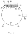
In Fig. 3 ist eine dritte Ausführungsform einer Vorrichtung 300 zum Nachweis eines
Fluoreszenzfarbstoffs F in einer Probe P dargestellt.FIG. 3 shows a third embodiment of a
Diese Vorrichtung unterscheidet sich von den in Fig. 1 gezeigten dadurch, daß anstelle
der Glasplatte 110 ein auf einem Substrat 315 vorgesehener Dünnfilm-Wellenleiter
310 verwendet wird, auf dessen Oberfläche die nachzuweisende Probe P mit dem
Fluoreszenzfarbstoff F aufgebracht ist. Außerdem wird anstelle des Prismas 111 ein
Gitterkoppler 311 zum Einkoppeln des Anregungslichts in dem Dünnfilm-Wellenleiter
310 verwendet.This device differs from that shown in Fig. 1 in that instead
of the
Abgesehen von dieser Einrichtung 310 zum Anregen des nachzuweisenden Fluoreszenzfarbstoffs
umfaßt die in Fig. 3 gezeigte Vorrichtung dieselben Merkmale wie die in
Fig. 1 dargestellte erste Ausführungsform. Um Wiederholungen zu vermeiden, wird in
bezug auf diese Komponenten deshalb lediglich auf die Beschreibung im Zusammenhang
mit Fig. 1 verwiesen, wobei anzumerken bleibt, daß sich die Bezugszeichen der
einander entsprechenden Komponenten lediglich in ihrer ersten Ziffer unterscheiden.Apart from this
Durch eine Lichteinkopplungseinrichtung wird Licht, das die Anregungswellenlänge
enthält, beispielsweise monochromatisches Laserlicht, in den Dünnfilm-Wellenleiter
310 so eingekoppelt, daß es parallel zur Oberfläche des Dünnfilm-Wellenleiters 310
durch denselben geleitet wird. Fluoreszenzfarbstoff F, der in einer auf dem Wellenleiter
aufgebrachten Probe P enthalten ist, wird durch das evaneszente Feld der sich
entlang des Dünnfilm-Wellenleiters 310 bewegenden Laserstrahlung angeregt. Die
durch den Fluoreszenzfarbstoff F emittierte Fluoreszenzstrahlung wird schließlich in
einen Hohlraum 330 gestrahlt wird und dort mit einer Detektoreinrichtung 320 nachgewiesen.Through a light coupling device, light that is the excitation wavelength
contains, for example, monochromatic laser light, in the
Der Dünnfilm-Wellenleiter 310 kann beispielsweise Ta2O5 umfassen. Weiterhin ist es
auch zweckmäßig, den Dünnfilm-Wellenleiter in seiner Dicke an die Anregungsstrahlung
anzupassen. So hat sich gezeigt, daß ein Dünnfilm-Wellenleiter aus Ta2O3 mit n
= 2,1 und einer Dicke von 100 nm für Argonlaserlicht mit λ = 488 nm gute Ergebnisse
liefert.The
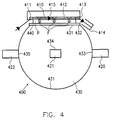
In Fig. 4 ist eine vierte Ausführungsform einer Vorrichtung 400 zum Nachweis eines
Fluoreszenzfarbstoffs F in einer Probe P dargestellt.FIG. 4 shows a fourth embodiment of a
Wie in der Ausführungsform gemäß Fig. 3 wird in dieser Vorrichtung ebenfalls ein
Dünnfilm-Wellenleiter 410, der auf einem Substrat 415 vorgesehen ist, verwendet.As in the embodiment according to FIG. 3, one is also in this device
Das zur Anregung des Fluoreszenzfarbstoffs zu verwendende Licht wird ebenfalls
über einen Gitterkoppler 411 in den Dünnfilm-Wellenleiter eingekoppelt. Im Gegensatz
zu dem in Fig. 3 gezeigten Dünnfilm-Wellenleiter 310 umfaßt der in Fig. 4 gezeigte
Dünnfilm-Wellenleiter 410 eine Auskopplungseinrichtung 413, die bevorzugt ebenfalls
in Form eines Gitterkopplers vorgesehen ist.The light to be used to excite the fluorescent dye also becomes
coupled into the thin-film waveguide via a
Analog zu der in Fig. 2 gezeigten Ausführungsform wird auch in dieser Ausführungsform
das ausgekoppelte Licht in eine Lichtfalle 414 geführt, um einen unkontrollierten
Eintritt in den Dünnfilm-Wellenleiter zu vermeiden.Analogous to the embodiment shown in FIG. 2 is also in this embodiment
the outcoupled light led into a
Die übrigen in Fig. 4 gezeigten Komponenten entsprechen in ihrer Funktionsweise und Wirkung den in Fig. 2 gezeigten Komponenten. Deshalb wird in bezug auf diese Komponenten lediglich auf die Beschreibung im Zusammenhang mit Fig. 2 verwiesen, wobei anzumerken bleibt, daß sich die Bezugszeichen einander entsprechender Komponenten lediglich in ihrer ersten Ziffer unterscheiden.The other components shown in FIG. 4 correspond in their mode of operation and effect of the components shown in FIG. 2. That is why regarding this Components only refer to the description in connection with FIG. 2, it should be noted that the reference numerals correspond to each other Only distinguish components in their first digit.
Claims (24)
gekennzeichnet durch
marked by
Applications Claiming Priority (2)
| Application Number | Priority Date | Filing Date | Title |
|---|---|---|---|
| DE19812681 | 1998-03-23 | ||
| DE1998112681 DE19812681A1 (en) | 1998-03-23 | 1998-03-23 | Device for detecting a fluorescent dye |
Publications (2)
| Publication Number | Publication Date |
|---|---|
| EP0949502A2 true EP0949502A2 (en) | 1999-10-13 |
| EP0949502A3 EP0949502A3 (en) | 1999-12-29 |
Family
ID=7861968
Family Applications (1)
| Application Number | Title | Priority Date | Filing Date |
|---|---|---|---|
| EP98123363A Withdrawn EP0949502A3 (en) | 1998-03-23 | 1998-12-08 | Device for detecting a fluorescent dye |
Country Status (2)
| Country | Link |
|---|---|
| EP (1) | EP0949502A3 (en) |
| DE (1) | DE19812681A1 (en) |
Cited By (1)
| Publication number | Priority date | Publication date | Assignee | Title |
|---|---|---|---|---|
| EP0947823A2 (en) * | 1998-04-03 | 1999-10-06 | Bodenseewerk Perkin-Elmer Gmbh | Device for detecting a fluorescent dye |
Citations (7)
| Publication number | Priority date | Publication date | Assignee | Title |
|---|---|---|---|---|
| US4583860A (en) * | 1983-11-30 | 1986-04-22 | The United States Of America As Represented By The Administrator Of The National Aeronautics And Space Administration | Optical multiple sample vacuum integrating sphere |
| US4900923A (en) * | 1988-06-03 | 1990-02-13 | Carl-Zeiss-Stiftung | Reflectance measuring apparatus including a cylinder-shaped light conducting device between the measuring aperture and the specimen |
| US5315375A (en) * | 1992-02-11 | 1994-05-24 | Acrogen, Inc. | Sensitive light detection system |
| US5408312A (en) * | 1990-09-28 | 1995-04-18 | Kim Yoon-Ok | Device for the qualitative and/or quantitative determination of the composition of a sample that is to be analyzed |
| WO1996037761A1 (en) * | 1995-05-26 | 1996-11-28 | Lxr Biotechnology Inc. | Multi-channel acquisition using integrating sphere |
| US5633724A (en) * | 1995-08-29 | 1997-05-27 | Hewlett-Packard Company | Evanescent scanning of biochemical array |
| US5636015A (en) * | 1995-05-17 | 1997-06-03 | Minolta Co., Ltd. | Measuring apparatus for measuring an optical property of a fluorescent sample |
-
1998
- 1998-03-23 DE DE1998112681 patent/DE19812681A1/en not_active Withdrawn
- 1998-12-08 EP EP98123363A patent/EP0949502A3/en not_active Withdrawn
Patent Citations (7)
| Publication number | Priority date | Publication date | Assignee | Title |
|---|---|---|---|---|
| US4583860A (en) * | 1983-11-30 | 1986-04-22 | The United States Of America As Represented By The Administrator Of The National Aeronautics And Space Administration | Optical multiple sample vacuum integrating sphere |
| US4900923A (en) * | 1988-06-03 | 1990-02-13 | Carl-Zeiss-Stiftung | Reflectance measuring apparatus including a cylinder-shaped light conducting device between the measuring aperture and the specimen |
| US5408312A (en) * | 1990-09-28 | 1995-04-18 | Kim Yoon-Ok | Device for the qualitative and/or quantitative determination of the composition of a sample that is to be analyzed |
| US5315375A (en) * | 1992-02-11 | 1994-05-24 | Acrogen, Inc. | Sensitive light detection system |
| US5636015A (en) * | 1995-05-17 | 1997-06-03 | Minolta Co., Ltd. | Measuring apparatus for measuring an optical property of a fluorescent sample |
| WO1996037761A1 (en) * | 1995-05-26 | 1996-11-28 | Lxr Biotechnology Inc. | Multi-channel acquisition using integrating sphere |
| US5633724A (en) * | 1995-08-29 | 1997-05-27 | Hewlett-Packard Company | Evanescent scanning of biochemical array |
Cited By (1)
| Publication number | Priority date | Publication date | Assignee | Title |
|---|---|---|---|---|
| EP0947823A2 (en) * | 1998-04-03 | 1999-10-06 | Bodenseewerk Perkin-Elmer Gmbh | Device for detecting a fluorescent dye |
Also Published As
| Publication number | Publication date |
|---|---|
| DE19812681A1 (en) | 1999-09-30 |
| EP0949502A3 (en) | 1999-12-29 |
Similar Documents
| Publication | Publication Date | Title |
|---|---|---|
| AT403745B (en) | MEASURING ARRANGEMENT WITH A TRANSPARENT ELEMENT FOR EXCITING AND MEASURING RADIATION | |
| DE3500247A1 (en) | DEVICE FOR ELIMINATING BACKGROUND INTERFERENCE IN FLUORESCENCE MEASUREMENTS | |
| DE3414261A1 (en) | INTERFERENCE REFRACTOMETER | |
| DE102015101847B4 (en) | Beam splitter and arrangement for the examination of a stimulable by electromagnetic radiation sample | |
| DE3741940C2 (en) | Color sensor | |
| EP0947823A2 (en) | Device for detecting a fluorescent dye | |
| EP0174496A2 (en) | Procedure for measuring the radiation wavelength and the wavelength-corrected radiation power of monochromatical light-sources and arrangement for carrying out this procedure | |
| EP0256280A2 (en) | Device for optical time domain reflectometry on optical fibres | |
| DE102013224463B4 (en) | Device for detecting fluorescence properties of samples | |
| DE2340354C2 (en) | Optical rapid analyzer | |
| DE3214051A1 (en) | SPECTRAL FLUOROMETER | |
| DE19507119C2 (en) | Device for determining impurities | |
| DE102004049541A1 (en) | Measuring system for measuring surfaces and calibration method therefor | |
| DE2948590C2 (en) | Device for measuring the absorption of gas mixtures | |
| DE69721910T2 (en) | Procedure for the calibration of a spectroscopic device | |
| EP0949502A2 (en) | Device for detecting a fluorescent dye | |
| DE10042003B4 (en) | Material testing device and its use | |
| DD159567B1 (en) | spectrofluorometer | |
| EP0950893A2 (en) | Apparatus for the detection of a fluorescent dye | |
| DE19848120C2 (en) | Device for measuring the radiation absorption of gases | |
| DE10033142C2 (en) | Exciter filter for an endoscope for fluorescence analysis | |
| EP0540715A1 (en) | Optical sensor | |
| DE19816359A1 (en) | Optical structural change detector for surface of moving part, especially adhesive layer | |
| DE10131724B4 (en) | Optical absorption measuring device | |
| EP0473940B1 (en) | Photometric device with scattering light trap |
Legal Events
| Date | Code | Title | Description |
|---|---|---|---|
| PUAI | Public reference made under article 153(3) epc to a published international application that has entered the european phase |
Free format text: ORIGINAL CODE: 0009012 |
|
| AK | Designated contracting states |
Kind code of ref document: A2 Designated state(s): DE FR GB IT |
|
| AX | Request for extension of the european patent |
Free format text: AL;LT;LV;MK;RO;SI |
|
| PUAL | Search report despatched |
Free format text: ORIGINAL CODE: 0009013 |
|
| AK | Designated contracting states |
Kind code of ref document: A3 Designated state(s): AT BE CH CY DE DK ES FI FR GB GR IE IT LI LU MC NL PT SE |
|
| AX | Request for extension of the european patent |
Free format text: AL;LT;LV;MK;RO;SI |
|
| RIC1 | Information provided on ipc code assigned before grant |
Free format text: 6G 01N 21/64 A, 6G 01N 21/55 B, 6G 01N 21/77 B |
|
| 17P | Request for examination filed |
Effective date: 20000221 |
|
| AKX | Designation fees paid |
Free format text: DE FR GB IT |
|
| 17Q | First examination report despatched |
Effective date: 20040510 |
|
| STAA | Information on the status of an ep patent application or granted ep patent |
Free format text: STATUS: THE APPLICATION IS DEEMED TO BE WITHDRAWN |
|
| 18D | Application deemed to be withdrawn |
Effective date: 20060601 |