EP0948978A2 - Image creating apparatus, image creating method, and computer-readable recording medium containing image creating program - Google Patents
Image creating apparatus, image creating method, and computer-readable recording medium containing image creating program Download PDFInfo
- Publication number
- EP0948978A2 EP0948978A2 EP99104074A EP99104074A EP0948978A2 EP 0948978 A2 EP0948978 A2 EP 0948978A2 EP 99104074 A EP99104074 A EP 99104074A EP 99104074 A EP99104074 A EP 99104074A EP 0948978 A2 EP0948978 A2 EP 0948978A2
- Authority
- EP
- European Patent Office
- Prior art keywords
- character
- image
- polygon
- model
- coordinates
- Prior art date
- Legal status (The legal status is an assumption and is not a legal conclusion. Google has not performed a legal analysis and makes no representation as to the accuracy of the status listed.)
- Granted
Links
Images


Classifications
-
- A63F13/10—
-
- A—HUMAN NECESSITIES
- A63—SPORTS; GAMES; AMUSEMENTS
- A63F—CARD, BOARD, OR ROULETTE GAMES; INDOOR GAMES USING SMALL MOVING PLAYING BODIES; VIDEO GAMES; GAMES NOT OTHERWISE PROVIDED FOR
- A63F13/00—Video games, i.e. games using an electronically generated display having two or more dimensions
- A63F13/50—Controlling the output signals based on the game progress
- A63F13/52—Controlling the output signals based on the game progress involving aspects of the displayed game scene
-
- A—HUMAN NECESSITIES
- A63—SPORTS; GAMES; AMUSEMENTS
- A63F—CARD, BOARD, OR ROULETTE GAMES; INDOOR GAMES USING SMALL MOVING PLAYING BODIES; VIDEO GAMES; GAMES NOT OTHERWISE PROVIDED FOR
- A63F13/00—Video games, i.e. games using an electronically generated display having two or more dimensions
- A63F13/45—Controlling the progress of the video game
-
- G—PHYSICS
- G06—COMPUTING; CALCULATING OR COUNTING
- G06T—IMAGE DATA PROCESSING OR GENERATION, IN GENERAL
- G06T15/00—3D [Three Dimensional] image rendering
- G06T15/50—Lighting effects
- G06T15/60—Shadow generation
-
- G—PHYSICS
- G06—COMPUTING; CALCULATING OR COUNTING
- G06T—IMAGE DATA PROCESSING OR GENERATION, IN GENERAL
- G06T17/00—Three dimensional [3D] modelling, e.g. data description of 3D objects
- G06T17/30—Polynomial surface description
-
- G—PHYSICS
- G06—COMPUTING; CALCULATING OR COUNTING
- G06T—IMAGE DATA PROCESSING OR GENERATION, IN GENERAL
- G06T19/00—Manipulating 3D models or images for computer graphics
- G06T19/20—Editing of 3D images, e.g. changing shapes or colours, aligning objects or positioning parts
-
- A—HUMAN NECESSITIES
- A63—SPORTS; GAMES; AMUSEMENTS
- A63F—CARD, BOARD, OR ROULETTE GAMES; INDOOR GAMES USING SMALL MOVING PLAYING BODIES; VIDEO GAMES; GAMES NOT OTHERWISE PROVIDED FOR
- A63F2300/00—Features of games using an electronically generated display having two or more dimensions, e.g. on a television screen, showing representations related to the game
- A63F2300/60—Methods for processing data by generating or executing the game program
- A63F2300/66—Methods for processing data by generating or executing the game program for rendering three dimensional images
- A63F2300/6646—Methods for processing data by generating or executing the game program for rendering three dimensional images for the computation and display of the shadow of an object or character
Definitions
- an image creating apparatus for using a viewpoint as a reference to create the image of a game character and the image of a model behind the game character in a virtual three-dimensional space and to display the images on a display means
- the image creating apparatus including a model-polygon storage means for storing the coordinates of model polygons constituting the model image; a character-polygon storage means for storing the coordinates of a two-dimensional character polygon forming the character image; a model-texture storage means for storing a texture indicating the model image; a character-texture storage means for storing a texture indicating the character image; a light-source storage means for storing the coordinates of a virtual light source provided in the three-dimensional space; a projection means for computing the shape of the character polygon which is projected onto the model image by the virtual light source; and a color-data setting means for setting color data on the obtained shape of the projected character image so as to represent
- the TV monitor 2, the amplification circuit 3, and the speaker 4 are provided separately from the main unit.
- all the components shown in Fig. 1 are integrated in a casing.
- Each command that uses polygons to render a three-dimensional image consists of a polygon-vertex-address data in the non-display area of the RAM 8; a texture-address data representing a position of the RAM 8 at which the texture data to be pasted on a polygon is stored; a color-address data representing a position in the display area of the RAM 8 at which the color data representing the color of a texture is stored; and a brightness data representing the brightness of the texture.
- the coordinate-transformation means 71 projects each vertex of polygons constituting the background models (hereinafter referred to as "model polygons") onto a plane including polygons (hereinafter referred to as "character polygons") constituting the leading character 31.
- the vertex is projected from a character-polygon-included plane onto the original polygon plane in step ST120, and the coordinates of a point of intersection is found in step ST270.
Abstract
Description
- The present invention relates to image creating apparatuses applied to video game machines using, for example, a cassette recording medium or the like in which an optical disk, a magnetic disk, or a semiconductor memory containing program data, is used, and to image creating methods therefor and recording media containing image recording programs.
- Many game systems have been proposed, such as a system comprised of a home-use game console and a television monitor, a commercial-use game machine, and a system comprised of a personal computer or work station, a display, and a sound output device.
- These game systems each include a player-operated controller, a recording medium containing game-program data, a central processing unit (CPU) for performing control for the generation of sound and images based on the game-program data, a processor for generating images, a processor for generating sound, a monitor for displaying images, and a speaker for outputting the generated sound. In many cases, the types of recording medium include a compact-disk read-only memory (CD-ROM), a semiconductor memory, and a cassette having a built-in semiconductor memory.
- In these game systems, in general, three-dimensional models as objects displayed on a screen are composed of polygons as a plurality of two-dimensional virtual triangular or square figures, and the polygons, on which textures such as two-dimensional image data are pasted, are displayed on the monitor. Normally, the textures to be pasted on the polygons are separately set and stored in a memory beforehand.
- In the case where these game systems use a two-dimensional character and background models behind the character, shading makes it very difficult to determine whether the character is on or in front of the background models.
- In order that the character may be clearly displayed so as to be disposed in front of the background models, it is demanded that a shadow of the character, formed on the background models, be displayed.
- Accordingly, it is an object of the present invention to provide an Image creating apparatus for displaying a shadow of a two-dimensional character image on background models, an image creating method therefor, and a computer-readable recording medium containing an image creating program.
- It is another object of the piesent invention to provide an image creating apparatus for displaying a character shadow without increasing an operation load, an image creating method therefor, and a computer-readable recording medium containing an image creating program.
- To these ends, according to an aspect of the present invention, the foregoing objects are achieved through provision of an image creating apparatus for using a viewpoint as a reference to create the image of a game character and the image of a model behind the game character in a virtual three-dimensional space and to display the images on a display means, the image creating apparatus including a model-polygon storage means for storing the coordinates of model polygons constituting the model image; a character-polygon storage means for storing the coordinates of a two-dimensional character polygon forming the character image; a model-texture storage means for storing a texture indicating the model image; a character-texture storage means for storing a texture indicating the character image; a light-source storage means for storing the coordinates of a virtual light source provided in the three-dimensional space; a projection means for computing the shape of the character polygon which is projected onto the model image by the virtual light source; and a color-data setting means for setting color data on the obtained shape of the projected character image so as to represent a shadow of the character.
- According to another aspect of the present invention, the foregoing objects are achieved through provision of an image creating method for using a viewpoint as a reference to create the image of a game character and the image of a model behind the game character in a virtual three-dimensional space and to display the images on a display unit, the image creating method including the steps of finding the shape of the character image as a two-dimensional image which is projected onto the model image as a three-dimensional image by a virtual light source provided in the virtual three-dimensional space; and setting color data on the obtained shape of the projected character image so as to represent a shadow of the character.
- According to a further aspect of the present invention, the foregoing objects are achieved through provision of a computer-readable recording medium containing an image creating program for using a viewpoint as a reference to create the image of a game character and the image of a model behind the game character in a virtual three-dimensional space and to display the images on a display means, wherein the image creating program comprises a first step for finding the shape of the character image as a two-dimensional image which is projected onto the model image as a three-dimensional image by a virtual light source provided in the virtual three-dimensional space; and a second step for setting color data on the obtained shape of the projected character image so as to represent a shadow of the character.
- According to the present invention, a shadow of a game character on models can be displayed, whereby the character can be clearly displayed so as to be in front of the models.
- According to the present invention, a shadow of a game character can be displayed on three-dimensional models, whereby the character shadow can be displayed with enhanced reality.
- According to the present invention, a shadow of a game character caused by a virtual light source can be displayed on a model area, whereby the character shadow can be displayed with reality, and the coordinates of a common polygon, whereby the character shadow can be displayed with reality, and the coordinates of a common polygon, which is formed by an area in which a projected polygon is superimposed on a character polygon, are two-dimensionally found, whereby an increase in an operation load can be prevented.
- Fig. 1 is a block diagram showing a game system according to an embodiment of the present invention.
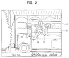
- Fig. 2 is a drawing showing a video-game screen.
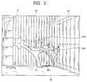
- Fig. 3 is a drawing showing a video-game screen.
- Fig. 4 is a block diagram showing the functional blocks of a central processing unit, and parts of the game system shown in Fig. 1.
- Fig. 5 is a drawing illustrating coordinate transformation.
- Fig. 6 is a drawing illustrating determination of superimposition of polygons.
- Fig. 7 is a drawing illustrating superimposition of a character polygon and a projected polygon.
- Fig. 8 is a drawing illustrating superimposition of a character polygon and a projected polygon.
- Fig. 9 is a flowchart showing an example of a process for displaying a shadow.
- Fig. 10 is a flowchart showing an example of a process for displaying a shadow.
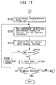
- Fig. 11 is a flowchart showing an example of a process for displaying a shadow.
-
- Fig. 1 shows a
game system 1 according to an embodiment of the present invention. - The
game system 1 includes a main unit, a television (TV)monitor 2 for outputting game images, anamplification circuit 3 and aspeaker 4 for outputting game sound, and arecording medium 5 containing game data comprised of images, sound, and program data. Therecording medium 5 is, for example, a so-called "read only memory (ROM) cassette" in which a ROM containing the game data and the program data of an operating system is accommodated in a plastic case, an optical disk, or a flexible disk. - In the main unit, a
bus 7 comprised of an address bus, a data bus, and a control bus (not shown), is connected to aCPU 6. A random access memory (RAM) 8, interface (I/F)circuits 9 and 10, asignal processing processor 11, animage processor 12, and I/F circuits bus 7. Acontroller 16 is connected to the I/F circuit 10 via an operation-information I/F circuit 15. A digital-to-analog (D/A)converter 17 is connected to the I/F circuit 13, and a D/A converter 18 is connected to the I/F circuit 14. - The
RAM 8, the I/F circuit 9, and therecording medium 5 constitute amemory unit 19. TheCPU 6, thesignal processor 11, and theimage processor 12 constitute acontroller 20 for controlling the progress of the game. The I/F circuit 10, the operation-information I/F circuit 15, and thecontroller 16 constitute anoperation input unit 21. TheTV monitor 2, the I/F circuit 13, and the D/A converter 17 constitute animage display unit 22. Theamplification circuit 3, thespeaker 4, the I/F circuit 14, and the D/A converter 18 constitute asound output unit 23. - The
signal processor 11 mainly performs computation in a three-dimensional space, computation for transformation from a position in a three-dimensional space into a position in a pseudo-three-dimensional space, illumination computation, and the generation and processing of sound data. - The
image processor 12 performs, based on a result of computation by thesignal processor 11, the writing of image data to be rendered in the display area of theRAM 8, for example, the writing of texture data to an area of theRAM 8 that is specified by polygons. The writing of the texture data is described below. - The
controller 16 has a start button 16a, an A-button 16b, a B-button 16c, across key 16d, acontrol stick 16e, aleft trigger button 16f, aright trigger button 16g, a C1-button 16h, a C2-button 16i, a C3-button 16j, a C4-button 16k, aconnector 16m, and adepth trigger button 16n. - A memory card or the like for temporarily storing the progress of the game can be set in the
connector 16m. - The form of the
game system 1 differs depending on its purpose. - In other words, in the case where the
game system 1 is intended for home use, theTV monitor 2, theamplification circuit 3, and thespeaker 4 are provided separately from the main unit. In the case where thegame system 1 is intended for commercial use, all the components shown in Fig. 1 are integrated in a casing. - In the case where the
game system 1 has a personal computer or workstation its core, theTV monitor 2 corresponds to a display for the computer or workstation, theimage processor 12 corresponds to part of the game program data recorded on therecording medium 5, or the hardware of an add-in board set in an add-in slot of the computer or workstation, and the I/F circuits A converters F circuit 15, correspond to the hardware of an add-in board set in an add-in slot of the computer or workstation. TheRAM 8 corresponds to the main memory of the computer or workstation, or to each area of an extension memory. - In the first embodiment, the case where the
game system 1 is intended for home use is described. - The operation of the
game system 1 is briefly described. - When the
game system 1 is supplied with power by turning on a main-power switch (not shown), theCPU 6 reads, based on an operating system recorded on therecording medium 5, images, sound, and game-program data from therecording medium 5. A portion or the entirety of the images, sound, and game-program data read by theCPU 6 is stored in theRAM 8. - Subsequently, the
CPU 6 proceeds with the game, based on the game-program data stored in theRAM 8, and on instructions input through thecontroller 16 by a game player. In other words, theCPU 6 generates, based on instructions from the game player via thecontroller 16, commands as tasks for rendering and sound output. - Based on the generated commands, the
signal processor 11 performs computation of the position of a game character in a three-dimensional space (similarly in a two-dimensional space), illumination computation, and the generation and processing of sound data. - Next, based on a result of the computation, the
image processor 12 performs the writing of image data to be rendered in the display area of theRAM 8. The image data written in theRAM 8 are supplied to the D/A converter 17 via the I/F circuit 13. The supplied image data are converted into analog video signals by the D/A converter 17. The video signals are supplied to theTV monitor 2, and are displayed as an image on the screen of theTV monitor 2. - The sound data output from the
signal processor 11 are supplied to the D/A converter 18 via the I/F circuit 14. The supplied sound data are converted into analog sound signals, and are output as sound from thespeaker 4 via theamplification circuit 3. - Next, the writing of texture data by the
image processor 12 is described with reference to Fig. 1. - As described above, the
signal processor 11 performs computation based on commands from theCPU 6, and theimage processor 12 performs, based on a result of the computation, the writing of image data to be rendered in the display area of theRAM 8. - The
RAM 8 has a non-display area and the display area (frame buffer). In the non-display area, information recorded on therecording medium 5, such as polygon data, texture-selection data, and color data (texture data), are stored. - The polygons are two-dimensional virtual polygonal figures constituting objects provided in the game space, that is, models and game characters. In the first embodiment, triangles and quadrangles are used as the polygons. The textures are two-dimensional images that are pasted on the polygons so that images are formed. The color data specify the colors of the textures.
- The polygon data, which are coordinate data on vertexes constituting the polygons, and the texture-selection data, which select textures corresponding to the polygons, are stored to be integrated.
- Commands for rendering, generated by the
CPU 6, include commands that use polygons to render three-dimensional images, and commands for rendering ordinary two-dimensional images. - Each command that uses polygons to render a three-dimensional image consists of a polygon-vertex-address data in the non-display area of the
RAM 8; a texture-address data representing a position of theRAM 8 at which the texture data to be pasted on a polygon is stored; a color-address data representing a position in the display area of theRAM 8 at which the color data representing the color of a texture is stored; and a brightness data representing the brightness of the texture. - Among these data, the polygon-vertex-address data in the non-display area of the
RAM 8 is replaced with a two-dimensional polygon-vertex-coordinate data by using thesignal processor 11 to perform, based on moving-quantity data and rotation-quantity data on a screen (viewpoint), coordinate transformation and the perspective projection transformation of polygon-vertex-coordinate data in a three-dimensional space from theCPU 6. - The two-dimensional polygon-vertex-address data represents an address in the display area of the
RAM 8. Theimage processor 12 writes a texture data represented by a pre-assigned texture-address data in a range of the display area of theRAM 8 which is represented by three or four polygon-vertex-address data. Thereby, objects expressed by pasting textures on polygons are displayed on the screen of theTV monitor 2. - The video game performed by the
game system 1 is briefly described with reference to Figs. 2 and 3. Figs. 2 and 3 show video game screens. - In the video game, a leading
character 31 moves about as shown in Fig. 2. The leadingcharacter 31 is a graffito that came out from the body of abus 32, and two-dimensionally consists of one polygon. - Background models provided further than the leading
character 31 from a viewpoint, such as the bus 32 (shown in Fig. 2), andwooden walls - In Figs. 2 and 3, a
shadow 36 of the leadingcharacter 31, caused by light from a virtual light source, is displayed. - In Fig. 2, the
shadow 36 of the leadingcharacter 31 is displayed with its portion lost along the surface of thebus 32. In Fig. 3, ashadow 36a on thewall 33 as a background, ashadow 36b on thewall 34 perpendicular to thewall 33, and ashadow 36c on aground 35 are displayed asshadows 36 of a leadingcharacter 31. - Fig. 4 shows a functional block diagram of the
CPU 6, and portions of thegame system 1. In Fig. 4, components between thebus 7 and each block are not shown. - In Fig. 4, the
recording medium 5 contains a program for a game performed in a game space (virtual three-dimensional space). The program includes the coordinates of one polygon two-dimensionally constituting the leading character (Fig. 2), the coordinates of polygons three-dimensionally constituting the bus 32 (Fig. 2), and thewalls - The program includes textures indicating various postures of the leading
character 31 as shown in Figs. 2 and 3, and textures indicating the respective background models. - The program includes data representing shades, as data specifying the colors of the textures.
- The
CPU 6 includes a projection means 61 and a color-data setting means 62. - The projection means 61 includes a coordinate-transformation means 71, a superimposition determination means 72, a polygon-operation means 73, a texture operation means 74, and a coordinate inverse-transformation means 75, and performs processing for displaying game character shades.
- Concerning displaying game-character shades, it is required that the shade of a game character be displayed only where the character is superimposed on a background model without being displayed where the character is superimposed. Accordingly, the superimposition portions are found by the projection means 61.
- The coordinate-transformation means 71 projects each vertex of polygons constituting the background models (hereinafter referred to as "model polygons") onto a plane including polygons (hereinafter referred to as "character polygons") constituting the leading
character 31. - The projection is performed by finding the coordinates of points at which straight lines between the vertices of a
polygon model 41 and avirtual source 42 intersect with aplane 44 including acharacter polygon 43. Apolygon 45 consisting of the respective points is hereinafter referred to as a "projected polygon". - The superimposition determination means 72 (shown in Fig. 4) determines whether the projection polygon 45 (shown in Fig. 5) is superimposed on the character polygon 43 (shown in Fig. 5).
- If the superimposition determination means 72 has determined that the projected
polygon 45 is superimposed on thecharacter polygon 43, the polygon-operation means 73 computes a vertex list of a common polygon formed by superimposition of thecharacter polygon 43 and the projectedpolygon 45. - The vertex list has coordinate data on the vertices of the common polygon, and data about the vertices. For creating the common polygon, it is required that not only the coordinate data on vertices but also the order of the vertices be known. Accordingly, the common polygon is created by computing the vertex list. In this embodiment, the order of the common polygon is set to be clockwise.
- The texture operation means 74 computes differences between the vertices of the common polygon and the vertices of the
character polygon 43, and computes, based on the differences, the texture coordinates of the common polygon. - This processing is performed in order that in the texture indicating the leading
character 31, only an area corresponding to the common polygon may be pasted onto an inversely projected polygon (described below). Thereby, theshadow 36 whose part is lost along the shape of thebus 32 can be displayed as shown in Fig. 2. - The coordinate inverse-transformation means 75 obtains an inversely projected polygon by projecting the obtained polygon onto the plane of the original polygon.
- This projection is performed, similarly to the projection by the coordinate-transformation means 71, by finding the coordinates of points at which lines between the vertices of the common polygon and the virtual
light source 42 intersect with a plane including themodel polygon 41. - The color-data setting means 62 sets, as texture-color data to be pasted onto the common polygon, color data (recorded on the recording medium 5) representing shade.
- The
image processor 12 pastes a texture based on set texture coordinates onto an inversely projected polygon obtained by projecting the common polygon onto the plane of the original model polygon. At the same time, theimage processor 12 writes a color data representing set shade in the display area of theRAM 8. - For obtaining a texture-color data, by mixing the color data representing set shade and a color data on the background model at a predetermined ratio, and writing the obtained color data in the display area of the
RAM 8, shade can be displayed with more virtual reality. - With reference to Figs. 6 to 8, a process for displaying shade is described based on the flowcharts shown in Figs. 9 to 11.
- Fig. 6 shows polygon superimposition determination. Figs. 7 and 8 show superimposition of the
character polygon 43 and the projectedpolygon 45. Fig. 9 shows a process for displaying shade. - In Fig. 9, in step ST100, the coordinates of a model polygon, recorded on the
recording medium 5, are read and stored in theRAM 8. In step ST110, the process determines whether the model polygon is displayed in the screen of theTV monitor 2 when a set position is used as a viewpoint. If no model polygon is displayed in the screen of the monitor 2 ("NO" in step ST110), the process returns to step ST100, and the coordinates of a polygon constituting the next model are read. - If there are the coordinates of the read polygon in the screen of the TV monitor 2 ("YES" in step ST110), the vertices of the polygon are projected onto a plane including a character polygon, and the coordinates of points of intersection are computed (step ST 120).
- In step ST130, maximum and minimum x- and y-coordinates of the projected polygon are computed.
- By way of example, in the case of a polygon comprised of vertices A0, A1, A2, and A3,
- a maximum of x-coordinates is represented by xmax,
- a minimum of x-coordinates is represented by xmin,
- a maximum of y-coordinates is represented by ymax, and
- a minimum of y-coordinates is represented by ymin.
-
- Referring back to Fig. 9, in step ST140, the process determines whether the projected is superimposed onto the character polygon. In other words, by using the maximum and minimum x- and y-coordinates of the projected polygon and the character polygon, it is determined whether both polygons can be superimposed onto each other.
- By way of example, when as to the projected polygon,
- a maximum of x-coordinates is represented by mxmax,
- a minimum of x-coordinates is represented by mxmin,
- a maximum of y-coordinates is represented by mymax, and
- a minimum of y-coordinates is represented by mymin, and as to the character polygon,
- a maximum of x-coordinates is represented by cxmax,
- a minimum of x-coordinates is represented by cxmin,
- a maximum of y-coordinates is represented by cymax, and
- a minimum of y-coordinates is represented by cymin,
among the following inequalities:
- cxmax <mxmin;
- cxmin > mxmax;
- cymax < mymin; and
- cymin > mymax; one inequality is satisfied, the process determines that both polygons cannot be superimposed onto each other.
-
- If both polygons cannot be superimposed ("NO" in step ST140), the process returns to step ST100.
- If both polygons can be superimposed ("YES" in step ST140), a vertex list on the character polygon, and a vertex list on the projected polygon are created in step ST150.
- A vertex list on the
character polygon 43 shown in Fig. 7 is represented by - C0(Cvtx0)-C1(Cvtx1)-C2(Cvtx2)-C3(Cvtx3)-C0(Cvtx0)-.... A vertex list on the
- M0(Mvtx0)-M1(Mvtx1)-M2(Mvtx2)-M3(Mvtx3)-M0(Mvtx0)-....
-
- In these numerical expressions, Cvtx0, Cvtx1, Cvtx2, and Cvtx3 represent coordinate data on vertices C0, C1, C2, and C3, respectively, and Mvtx0, Mvtx1, Mvtx2, and Mvtx3 represent coordinate data on vertices M0, M1, M2, and M3, respectively.
- In step ST160 (shown in Fig. 9), one line segment (hereinafter referred to as a "model line segment") forming one side of the projected
polygon 45 is fetched. - In step ST170 (shown in Fig. 10), by using, for example, a known flag-status determination technique, it is determined whether the model line segment intersects with each line segment (hereinafter referred to as a "character line segment") constituting the
character polygon 43. - If both line segments do not intersect ("NO" in step ST170), the process proceeds to step ST180. If both line segments intersect ("YES" in step ST170), the coordinates of points at which both line segments intersect are computed in step ST190.
- In step ST200, the process determines whether there is the initial point of the model line segment outside the
character polygon 43. If there is not the initial point outside the character polygon 43 ("NO" in step ST200), the process proceeds to step ST230. - If, in step ST200, the initial point of the model line segment is outside the character polygon 43 ("YES" in step ST200), in step ST220, the coordinate data (in the vertex list of the projected polygon) on the initial point of the model segment having intersected are replaced by coordinate data on vertices of intersection, and the replaced coordinate data are combined with the vertex list on the
character polygon 43. The process returns to step ST170, and it determines whether the model line segment intersects with another character segment. - In step ST230, the coordinate data (in the vertex list of the character polygon 43) on the initial point of the character line segment having intersected are replaced by coordinate data on vertices of intersection, and the replaced coordinate data are combined with the vertex list on the projected polygon. The process returns to step ST170, and it determines whether the model line segment intersects with another character segment.
- In step ST180, the process determines whether no model line segment to be fetched is detected. If a model line segment is detected ("NO" in step ST180), the next model line segment is fetched (step ST240) before the process returns to step ST170. If no model line segment is detected ("YES" in step ST180), the process proceeds to step ST250 (shown in Fig. 11).
- With reference to Fig. 7, steps ST160 to ST240 are described. In Fig. 7, a coordinate data on vertex P0 of intersection is represented by Pvtx0, and a coordinate data on vertex P1 of intersection is represented by Pvtx1.
- When model line segment M0m1 is fetched in step ST160, coordinate data Pvtx0 on vertex P0 of intersection is computed in step ST190 because the line segment intersects with character line segment C1C2. Since the terminal point M1 of the model line segment M0M1 is outside, the process proceeds from step ST200 to step ST230.
- In step ST230, in the following vertex list on the character polygon 43:
- C0(Cvtx0)-C1(Cvtx1)-C2(Cvtx2)-C3(Cvtx3)-C0(Cvtx0)-..., a coordinate data on the initial point C1 of character line segment C1C2 having intersected is replaced by a coordinate data on vertex P0 of intersection. Thereby, the vertex list on the
- C0(Cvtx0)-C1(Pvtx0)-C2(Cvtx2)-C3(Cvtx3)-C0(Cvtx0)-....
-
- In addition, in the following vertex list on the projected polygon 45:
- M0(Mvtx0)-M1(Mvtx1)-M2(Mvtx2)-M3(Mvtx3)-M0(Mvtx0)-..., lists after coordinate data Pvtx0 (in the vertex list on the character polygon 43) on vertex P0 of intersection are combined with the initial point M0 of model line segment M0M1 having intersected.
-
- Thereby, the desired vertex list:
- M0(Mvtx0)-C1(Pvtx0)-C2(Cvtx2)-C3(Cvtx3)-C0(Cvtx0)-C1(Pvtx0)-... is temporarily obtained.
-
- In step ST240, model line segments M1M2 and M2M3 are fetched. The desired vertex list does not change since both line segments do not intersect with the character line segment ("NO" in step ST170).
- When model line segment M3M0 is fetched in step ST240, coordinate data Pvtx1 on vertex P1 of intersection is computed in step ST190 because the line segment M3M0 intersects with character line segment C2C3. The initial point M3 of line segment M3M0 is outside the common polygon. Accordingly, the process proceeds from step ST200 to step ST220.
- In step ST220, in the vertex list on the projected
polygon 45, a coordinate data on the initial point M3 of line segment M3M0 having intersected is replaced by a coordinate data on vertex P1 of intersection. - In the temporarily obtained, desired vertex list, a vertex having a coordinate data on vertex P1 of intersection, that is, vertex M3, is combined with the initial point of line segment C2C3.
- Thereby, the desired vertex list:
- M0(Mvtx0)-C1(Pvtx0)-C2(Cvtx2)-M3(Pvtx1)-M0(Mvtx0)-C1(Pvtx0)-... is finally obtained.
-
- This vertex list has coordinate data on the vertices of the common polygon (the shading portion shown in Fig. 7) formed by intersection of the
character polygon 43 and the projectedpolygon 45, and data on the order of the vertices. - Steps ST160 to ST240 for other superimposition of the
character polygon 43 and the projectedpolygon 45 are described with reference to Fig. 8. In Fig. 8, a coordinate data on vertex Q0 of intersection is represented by Qvtx0, and a coordinate data on vertex Q1 of intersection is represented by Qvtx1. - When model fine segment M0M1 is fetched in step ST160, the process determines negatively ("NO" in step ST170) since model line segment M0M1 does not intersect with the
character polygon 43, and the next model line segment M1M2 is fetched. Since the fetched line segment M1M2 intersects with character line segment C0C1, in step ST190, coordinate data Qvtx0 on vertex Q0 of intersection is computed. The initial point M1 of model line segment M1M2 is outside the common polygon. Accordingly, the process proceeds from step ST200 to step ST220. - In step ST220, in the following vertex list on the projected
polygon 45; - M0(Mvtx0)-M1(Mvtx1)-M2(Mvtx2)-M3(Mvtx3)-M0(Mvtx0)-..., the coordinate data on the initial point M1 of model line segment M1M2 having intersected is replaced by the coordinate data on vertex Q1 of intersection. Thereby, the vertex list on the projected
- M0(Mvtx0)-M1(Qvtx0)-M2(Mvtx2)-M3(Mvtx3)-M0(Mvtx0)-....
-
- In the following vertex list on the character polygon 43:
- C0(Cvtx0)-C1(Cvtx1)-C2(Cvtx2)-C3(Cvtx3)-C0(Cvtx0)-..., the vertex based on coordinate data Qvtx of vertex Q0 of intersection in the vertex list on the projected
-
- Thereby, the temporary, desired vertex list:
- C0(Cvtx0)-M1(Qvtx0)-M2(Mvtx2)-M3(Mvtx3)-M0(Mvtx0)-M1(Qvtx0)-... is obtained.
-
- When model line segment M2M3 is fetched in step ST240, coordinate data Qvtx1 on vertex Q1 of intersection is computed in step ST190 because the fetched line segment intersects with character line segment C3C0. The end point M3 of model line segment M2M3 is outside the common polygon. Accordingly, the process proceeds from step ST210 to step ST230.
- In step ST230, in the vertex list on the
character polygon 43, the coordinate data on initial point C3, which is out of character line segment C3C0 is replaced, by the coordinate data on vertex Q1 of intersection. - In the temporary, desired vertex list, a vertex having the coordinate data on character polygon vertex Q1 of intersection, that is, vertex C3, is combined with initial point M2 inner than model line segment M2M3 having intersected.
- Thereby, the final, desired vertex list:
- C0(Cvtx0)-M1(Qvtx0)-M2(Mvtx2)-C3(Qvtx1)-C0(Cvtx0)-M1(Qvtx0)-... is obtained.
-
- The obtained, desired vertex list has coordinate data on the vertices of the common polygon (the shading part shown in Fig. 8) formed by intersection of the
character polygon 43 and the projectedpolygon 45, and data on the order of the vertices. - Referring back to Fig. 11, step ST250 and the subsequent steps are described.
- In step ST250, a vertex (e.g., vertex M0 in Fig. 7) is fetched from the obtained vertex list. In step ST260, the difference between the fetched vertex and a reference vertex (e.g., vertex C0 in Fig. 7) of the
character polygon 43 is found, and the texture coordinates of the fetched vertex are found based on the difference. - The vertex is projected from a character-polygon-included plane onto the original polygon plane in step ST120, and the coordinates of a point of intersection is found in step ST270.
- In step ST280, it is determined whether a vertex to be fetched has been detected. If a vertex to be fetched is detected ("NO" in step ST280), the next vertex (e.g., vertex P0 in Fig. 7) in the vertex list is fetched in step ST290, and the process returns to step ST260.
- If no vertex to be fetched is detected ("YES" in step ST280), data on the obtained vertex list, and the texture coordinate data are sent from the
CPU 6 to theimage processor 12 in step ST300. - Next, in step ST310, it is determined whether a polygon model has been detected. If a polygon model has been detected ("NO" in step ST310), the process returns to step ST100 (shown in Fig. 9). If no polygon model has been detected ("YES" in step ST310), the process ends.
- For the background models such as the bus 32 (shown in Fig. 2), the
wooden walls - As described above, according to this embodiment, by displaying the
shadow 36 of the two-dimensionalleading character 31 on background models, the leadingcharacter 31 can be clearly displayed so as to be closer to a viewpoint than the background models, namely, the bus 32 (shown in Fig. 2) and thewooden walls 33 and 34 (shown in Fig. 3). - By displaying the
shadow 36 on three-dimensional background models, the virtual reality of theshadow 36 can be enhanced. - By projecting a model polygon onto a plane including a character polygon so that a projected polygon is computed, and determining in a two-dimensional system whether the character polygon is superimposed on the projected polygon, a common polygon can be easily computed without an increase in computing load.
- The present invention is not limited to the above-described embodiment. However, the following modifications (1) to (3) of the present invention may be employed.
- (1) Not only coordinate data actually used for rendering on a monitor, but also simplified coordinate data including necessarily minimum shape data, may be used as coordinate data on polygons constituting background models.
- (2) The position of a virtual light source may be set to be far from a leading character, for example, at an approximately infinite distant position. In this case, a virtual effect in which a shadow formed by sunlight is expressed can be obtained.
- (3) The functional blocks of the projection means 61 may have the following functions. The coordinate-transformation means 71 finds the vertices of a three-dimensionally transformed polygon comprised of points at which straight lines between the vertices of a character polygon and a virtual light source intersect with a model polygon. The superimposition determination means 72 determines whether the three-dimensionally transformed polygon is superimposed on the model polygon. The polygon-operation means 73 computes a superimposition polygon composed of an area on which the three-dimensionally transformed polygon is superimposed on the model polygon.
-
- The texture operation means 74 projects the superimposition polygon onto a plane including the character polygon, similarly to projection by the coordinate-transformation means 71 in the above-described embodiment. The texture operation means 74 computes differences between the coordinates of the projected polygon and the coordinates of the character polygon, and computes, based on the difference, the texture coordinates of the superimposition polygon.
- Also, in this modification, a shadow can be displayed as in the above-described embodiment. This modification eliminates the need for the coordinate inverse-transformation means 75 as a functional block of the projection means 61.
Claims (6)
- An image creating apparatus for using a viewpoint as a reference to create the image of a game character and the image of a model behind said game character in a virtual three-dimensional space and to display the images on a display means, said image creating apparatus characterized by comprising:model-polygon storage means for storing the coordinates of model polygons constituting the model image;character-polygon storage means for storing the coordinates of a two-dimensional character polygon forming the character image;model-texture storage means for storing a texture indicating the model image;character-texture storage means for storing a texture indicating the character image;light-source storage means for storing the coordinates of a virtual light source provided in said three-dimensional space;projection means for computing the shape of said character polygon which is projected onto the model image by said virtual light source; andcolor-data setting means for setting color data on the obtained shape of the projected character image so as to represent a shadow of said character.
- An image creating apparatus according to Claim 1, wherein the model image stored in said model-polygon storage means comprises a plurality of three-dimensional model polygons as said model polygons.
- An image creating apparatus according to Claim 1 or 2, wherein said projection means comprises:coordinate-transformation means for computing the coordinates of a projected polygon comprised of points at which straight lines between the vertices of each model polygon and said virtual light source intersect with a plane including said character polygon;polygon-operation means for computing the coordinates of a common polygon formed by an area on which said projected polygon is superimposed on said character polygon;texture operation means for computing the texture coordinates of said common polygon, based on differences between the coordinates of said character polygon and the coordinates of said common polygon; andcoordinate inverse-transformation means for computing the coordinates of an inversely projected polygon comprised of points at which straight lines between the coordinates of said common polygon and said virtual light source intersect with a plane including said model polygon; and
wherein said color-data setting means sets color data on said inversely projected polygon so as to represent the shadow. - An image creating apparatus according to any one of Claims 1 to 3, wherein said color-data setting means uses, as said color data representing the shadow of said character, data obtained by increasing the concentration of color data on the texture image stored in said model-texture storage means.
- An image creating method for using a viewpoint as a reference to create the image of a game character and the image of a model behind said game character in a virtual three-dimensional space and to display the images on a display means, said image creating method characterized by comprising the steps of:finding the shape of the character image as a two-dimensional image which is projected onto the model image as a three-dimensional image by a virtual light source provided in said virtual three-dimensional space; andsetting color data on the obtained shape of the projected character image so as to represent a shadow of said character.
- A computer-readable recording medium containing an image creating program for using a viewpoint as a reference to create the image of a game character and the image of a model behind said game character in a virtual three-dimensional space and to display the images on a display means, said computer-readable recording medium characterized in that said image creating program comprises:a first step for finding the shape of the character image as a two-dimensional image which is projected onto the model image as a three-dimensional image by a virtual light source provided in said virtual three-dimensional space; anda second step for setting color data on the obtained shape of the projected character image so as to represent a shadow of said character.
Applications Claiming Priority (2)
| Application Number | Priority Date | Filing Date | Title |
|---|---|---|---|
| JP10071063A JP2976963B2 (en) | 1998-03-19 | 1998-03-19 | Image creation device, image creation method, readable recording medium on which image creation program is recorded, and video game device |
| JP7106398 | 1998-03-19 |
Publications (3)
| Publication Number | Publication Date |
|---|---|
| EP0948978A2 true EP0948978A2 (en) | 1999-10-13 |
| EP0948978A3 EP0948978A3 (en) | 2001-04-18 |
| EP0948978B1 EP0948978B1 (en) | 2006-10-04 |
Family
ID=13449705
Family Applications (1)
| Application Number | Title | Priority Date | Filing Date |
|---|---|---|---|
| EP99104074A Expired - Lifetime EP0948978B1 (en) | 1998-03-19 | 1999-03-18 | Image creating apparatus, image creating method, and computer-readable recording medium containing image creating program |
Country Status (7)
| Country | Link |
|---|---|
| EP (1) | EP0948978B1 (en) |
| JP (1) | JP2976963B2 (en) |
| KR (1) | KR100647861B1 (en) |
| CN (1) | CN1129872C (en) |
| DE (1) | DE69933406T2 (en) |
| HK (1) | HK1022443A1 (en) |
| TW (1) | TW457110B (en) |
Cited By (5)
| Publication number | Priority date | Publication date | Assignee | Title |
|---|---|---|---|---|
| WO2000054224A1 (en) * | 1999-03-08 | 2000-09-14 | Sony Computer Entertainment Inc. | Method and apparatus for processing images |
| EP1184811A2 (en) * | 2000-08-31 | 2002-03-06 | Konami Corporation | Three-dimensional image processing method and apparatus and video game system |
| EP1208887A2 (en) * | 2000-11-22 | 2002-05-29 | Sony Computer Entertainment Inc. | Object control method |
| US6924798B2 (en) * | 2001-05-22 | 2005-08-02 | Intel Corporation | Real-time multi-resolution shadows |
| EP2209093A1 (en) * | 2007-09-28 | 2010-07-21 | Konami Digital Entertainment Co., Ltd. | Image generating device, image generating method, information recording medium, and program |
Families Citing this family (6)
| Publication number | Priority date | Publication date | Assignee | Title |
|---|---|---|---|---|
| JP3369159B2 (en) | 2000-02-17 | 2003-01-20 | 株式会社ソニー・コンピュータエンタテインメント | Image drawing method, image drawing apparatus, recording medium, and program |
| JP4065507B2 (en) * | 2002-07-31 | 2008-03-26 | キヤノン株式会社 | Information presentation apparatus and information processing method |
| JP2004246877A (en) * | 2003-01-24 | 2004-09-02 | Sega Corp | Program projecting image onto game character, game machine incorporating program, storage medium storing program |
| EP1962980A1 (en) * | 2005-12-16 | 2008-09-03 | Koninklijke Philips Electronics N.V. | Shadow generation apparatus and method |
| JP4852555B2 (en) * | 2008-01-11 | 2012-01-11 | 株式会社コナミデジタルエンタテインメント | Image processing apparatus, image processing method, and program |
| JP2016528647A (en) | 2013-08-22 | 2016-09-15 | ヒューレット−パッカード デベロップメント カンパニー エル.ピー.Hewlett‐Packard Development Company, L.P. | Projective computing system |
Citations (4)
| Publication number | Priority date | Publication date | Assignee | Title |
|---|---|---|---|---|
| US4600200A (en) * | 1982-01-14 | 1986-07-15 | Ikegami Tsushinki Co., Ltd. | Three-dimensional image display system |
| WO1996025211A1 (en) * | 1995-02-17 | 1996-08-22 | Namco Ltd. | Three-dimensional game device and picture synthesis method |
| US5616031A (en) * | 1991-03-21 | 1997-04-01 | Atari Games Corporation | System and method of shadowing an object in motion |
| WO1998048381A1 (en) * | 1997-04-18 | 1998-10-29 | At & T Corp. | Integration of monocular cues to improve depth perception |
Family Cites Families (1)
| Publication number | Priority date | Publication date | Assignee | Title |
|---|---|---|---|---|
| JP3667393B2 (en) * | 1995-08-04 | 2005-07-06 | 株式会社ナムコ | 3D game device and image composition method |
-
1998
- 1998-03-19 JP JP10071063A patent/JP2976963B2/en not_active Expired - Fee Related
-
1999
- 1999-02-11 KR KR1019990004788A patent/KR100647861B1/en not_active IP Right Cessation
- 1999-03-16 TW TW088104037A patent/TW457110B/en not_active IP Right Cessation
- 1999-03-18 EP EP99104074A patent/EP0948978B1/en not_active Expired - Lifetime
- 1999-03-18 DE DE69933406T patent/DE69933406T2/en not_active Expired - Lifetime
- 1999-03-19 CN CN99103069A patent/CN1129872C/en not_active Expired - Fee Related
-
2000
- 2000-03-02 HK HK00101343A patent/HK1022443A1/en not_active IP Right Cessation
Patent Citations (4)
| Publication number | Priority date | Publication date | Assignee | Title |
|---|---|---|---|---|
| US4600200A (en) * | 1982-01-14 | 1986-07-15 | Ikegami Tsushinki Co., Ltd. | Three-dimensional image display system |
| US5616031A (en) * | 1991-03-21 | 1997-04-01 | Atari Games Corporation | System and method of shadowing an object in motion |
| WO1996025211A1 (en) * | 1995-02-17 | 1996-08-22 | Namco Ltd. | Three-dimensional game device and picture synthesis method |
| WO1998048381A1 (en) * | 1997-04-18 | 1998-10-29 | At & T Corp. | Integration of monocular cues to improve depth perception |
Non-Patent Citations (2)
| Title |
|---|
| ATHERTON P. ET AL: 'Polygon Shadow Generation' PROC. INT. CONF. ON COMPUTER GRAPHICS AND INTERACTIVE TECHNIQUES vol. 12, August 1978, pages 275 - 281 * |
| BOUKNIGHT W.J.: 'A Procedure for Generation of Three-dimensional Half-toned Computer Graphics Presentations' COMMUNICATIONS OF THE ACM vol. 13, no. 9, September 1970, pages 527 - 536 * |
Cited By (10)
| Publication number | Priority date | Publication date | Assignee | Title |
|---|---|---|---|---|
| WO2000054224A1 (en) * | 1999-03-08 | 2000-09-14 | Sony Computer Entertainment Inc. | Method and apparatus for processing images |
| US6677946B1 (en) | 1999-03-08 | 2004-01-13 | Sony Computer Entertainment Inc. | Method of, an apparatus for, and a recording medium comprising a program for, processing an image |
| EP1184811A2 (en) * | 2000-08-31 | 2002-03-06 | Konami Corporation | Three-dimensional image processing method and apparatus and video game system |
| EP1184811A3 (en) * | 2000-08-31 | 2002-09-18 | Konami Corporation | Three-dimensional image processing method and apparatus and video game system |
| US6888547B2 (en) | 2000-08-31 | 2005-05-03 | Konami Corporation | Three-dimensional image processing method and apparatus, readable storage medium storing three-dimensional image processing program and video game system |
| EP1208887A2 (en) * | 2000-11-22 | 2002-05-29 | Sony Computer Entertainment Inc. | Object control method |
| EP1208887A3 (en) * | 2000-11-22 | 2005-01-19 | Sony Computer Entertainment Inc. | Object control method |
| US6924798B2 (en) * | 2001-05-22 | 2005-08-02 | Intel Corporation | Real-time multi-resolution shadows |
| EP2209093A1 (en) * | 2007-09-28 | 2010-07-21 | Konami Digital Entertainment Co., Ltd. | Image generating device, image generating method, information recording medium, and program |
| EP2209093A4 (en) * | 2007-09-28 | 2011-10-19 | Konami Digital Entertainment | Image generating device, image generating method, information recording medium, and program |
Also Published As
| Publication number | Publication date |
|---|---|
| HK1022443A1 (en) | 2000-08-11 |
| DE69933406D1 (en) | 2006-11-16 |
| EP0948978A3 (en) | 2001-04-18 |
| KR19990077421A (en) | 1999-10-25 |
| CN1231460A (en) | 1999-10-13 |
| KR100647861B1 (en) | 2006-11-24 |
| JPH11272882A (en) | 1999-10-08 |
| DE69933406T2 (en) | 2007-08-16 |
| CN1129872C (en) | 2003-12-03 |
| JP2976963B2 (en) | 1999-11-10 |
| TW457110B (en) | 2001-10-01 |
| EP0948978B1 (en) | 2006-10-04 |
Similar Documents
| Publication | Publication Date | Title |
|---|---|---|
| JP3637031B2 (en) | GAME DEVICE AND GAME PROGRAM | |
| JP3824788B2 (en) | Video game apparatus, game screen viewpoint switching method in video game, and computer-readable recording medium recorded with game screen viewpoint switching program in video game | |
| US7104891B2 (en) | Game machine and game program for displaying a first object casting a shadow formed by light from a light source on a second object on a virtual game space | |
| JP4833674B2 (en) | GAME DEVICE, GAME DEVICE CONTROL METHOD, AND PROGRAM | |
| JP2004329463A (en) | Game device and control program of virtual camera | |
| US6897865B2 (en) | Three-dimensional image processing method and apparatus, readable storage medium storing three-dimensional image processing program and video game system | |
| JP2006068138A (en) | Game apparatus and image processing program | |
| JP2007226707A (en) | Gaming device and game program | |
| US6781592B2 (en) | Image generating device, image generating method, readable storage medium storing image generating program, and video game device | |
| EP0948978B1 (en) | Image creating apparatus, image creating method, and computer-readable recording medium containing image creating program | |
| US20020034979A1 (en) | Video game system, character action control method, and readable storage medium storing character action control program | |
| EP0992267B1 (en) | Image creating apparatus, displayed scene switching method for the image creating apparatus, computer-readable recording medium containing displayed scene switching program for the image creating apparatus, and video game machine | |
| JP3926828B1 (en) | GAME DEVICE, GAME DEVICE CONTROL METHOD, AND PROGRAM | |
| US6326967B1 (en) | Image creating apparatus, image creating method, and computer-readable recording medium containing image creating program | |
| JP3001538B1 (en) | VIDEO GAME DEVICE, MODEL DISPLAY METHOD FOR VIDEO GAME, AND READABLE RECORDING MEDIUM ON WHICH MODEL DISPLAY PROGRAM FOR VIDEO GAME IS RECORDED | |
| EP1362622B1 (en) | Video game apparatus and control method thereof | |
| JP2004318558A (en) | Image processor and image processing program | |
| US7245298B2 (en) | Game system, image drawing method for game system, and computer-readable storage medium storing game program | |
| JP3839355B2 (en) | GAME DEVICE AND GAME PROGRAM | |
| KR20020013891A (en) | Method and apparatus for generating images | |
| KR20010113781A (en) | Method and apparatus for performing perspective transformation | |
| JP4219766B2 (en) | Image generation program and image generation apparatus |
Legal Events
| Date | Code | Title | Description |
|---|---|---|---|
| PUAI | Public reference made under article 153(3) epc to a published international application that has entered the european phase |
Free format text: ORIGINAL CODE: 0009012 |
|
| AK | Designated contracting states |
Kind code of ref document: A2 Designated state(s): DE FR GB |
|
| AX | Request for extension of the european patent |
Free format text: AL;LT;LV;MK;RO;SI |
|
| PUAL | Search report despatched |
Free format text: ORIGINAL CODE: 0009013 |
|
| AK | Designated contracting states |
Kind code of ref document: A3 Designated state(s): AT BE CH CY DE DK ES FI FR GB GR IE IT LI LU MC NL PT SE |
|
| AX | Request for extension of the european patent |
Free format text: AL;LT;LV;MK;RO;SI |
|
| RIC1 | Information provided on ipc code assigned before grant |
Free format text: 7A 63F 9/22 A, 7G 06T 15/50 B |
|
| 17P | Request for examination filed |
Effective date: 20010628 |
|
| AKX | Designation fees paid |
Free format text: DE FR GB |
|
| 17Q | First examination report despatched |
Effective date: 20040203 |
|
| GRAP | Despatch of communication of intention to grant a patent |
Free format text: ORIGINAL CODE: EPIDOSNIGR1 |
|
| RIC1 | Information provided on ipc code assigned before grant |
Ipc: 7G 06T 15/50 B Ipc: 7A 63F 13/00 A |
|
| GRAS | Grant fee paid |
Free format text: ORIGINAL CODE: EPIDOSNIGR3 |
|
| GRAA | (expected) grant |
Free format text: ORIGINAL CODE: 0009210 |
|
| AK | Designated contracting states |
Kind code of ref document: B1 Designated state(s): DE FR GB |
|
| REG | Reference to a national code |
Ref country code: GB Ref legal event code: FG4D |
|
| REF | Corresponds to: |
Ref document number: 69933406 Country of ref document: DE Date of ref document: 20061116 Kind code of ref document: P |
|
| REG | Reference to a national code |
Ref country code: HK Ref legal event code: GR Ref document number: 1022443 Country of ref document: HK |
|
| ET | Fr: translation filed | ||
| PLBE | No opposition filed within time limit |
Free format text: ORIGINAL CODE: 0009261 |
|
| STAA | Information on the status of an ep patent application or granted ep patent |
Free format text: STATUS: NO OPPOSITION FILED WITHIN TIME LIMIT |
|
| 26N | No opposition filed |
Effective date: 20070705 |
|
| REG | Reference to a national code |
Ref country code: GB Ref legal event code: 732E Free format text: REGISTERED BETWEEN 20090514 AND 20090520 |
|
| REG | Reference to a national code |
Ref country code: FR Ref legal event code: TP Ref country code: FR Ref legal event code: CD Ref country code: FR Ref legal event code: CA |
|
| PGFP | Annual fee paid to national office [announced via postgrant information from national office to epo] |
Ref country code: DE Payment date: 20130321 Year of fee payment: 15 Ref country code: FR Payment date: 20130408 Year of fee payment: 15 Ref country code: GB Payment date: 20130321 Year of fee payment: 15 |
|
| REG | Reference to a national code |
Ref country code: DE Ref legal event code: R119 Ref document number: 69933406 Country of ref document: DE |
|
| GBPC | Gb: european patent ceased through non-payment of renewal fee |
Effective date: 20140318 |
|
| REG | Reference to a national code |
Ref country code: FR Ref legal event code: ST Effective date: 20141128 |
|
| REG | Reference to a national code |
Ref country code: DE Ref legal event code: R119 Ref document number: 69933406 Country of ref document: DE Effective date: 20141001 |
|
| PG25 | Lapsed in a contracting state [announced via postgrant information from national office to epo] |
Ref country code: GB Free format text: LAPSE BECAUSE OF NON-PAYMENT OF DUE FEES Effective date: 20140318 Ref country code: FR Free format text: LAPSE BECAUSE OF NON-PAYMENT OF DUE FEES Effective date: 20140331 Ref country code: DE Free format text: LAPSE BECAUSE OF NON-PAYMENT OF DUE FEES Effective date: 20141001 |