EP0945552A1 - Fender and a management system therefor - Google Patents
Fender and a management system therefor Download PDFInfo
- Publication number
- EP0945552A1 EP0945552A1 EP98947964A EP98947964A EP0945552A1 EP 0945552 A1 EP0945552 A1 EP 0945552A1 EP 98947964 A EP98947964 A EP 98947964A EP 98947964 A EP98947964 A EP 98947964A EP 0945552 A1 EP0945552 A1 EP 0945552A1
- Authority
- EP
- European Patent Office
- Prior art keywords
- information
- fender
- transponder
- memory means
- control system
- Prior art date
- Legal status (The legal status is an assumption and is not a legal conclusion. Google has not performed a legal analysis and makes no representation as to the accuracy of the status listed.)
- Granted
Links
Images


Classifications
-
- G—PHYSICS
- G06—COMPUTING; CALCULATING OR COUNTING
- G06Q—INFORMATION AND COMMUNICATION TECHNOLOGY [ICT] SPECIALLY ADAPTED FOR ADMINISTRATIVE, COMMERCIAL, FINANCIAL, MANAGERIAL OR SUPERVISORY PURPOSES; SYSTEMS OR METHODS SPECIALLY ADAPTED FOR ADMINISTRATIVE, COMMERCIAL, FINANCIAL, MANAGERIAL OR SUPERVISORY PURPOSES, NOT OTHERWISE PROVIDED FOR
- G06Q10/00—Administration; Management
- G06Q10/08—Logistics, e.g. warehousing, loading or distribution; Inventory or stock management
- G06Q10/087—Inventory or stock management, e.g. order filling, procurement or balancing against orders
-
- B—PERFORMING OPERATIONS; TRANSPORTING
- B63—SHIPS OR OTHER WATERBORNE VESSELS; RELATED EQUIPMENT
- B63B—SHIPS OR OTHER WATERBORNE VESSELS; EQUIPMENT FOR SHIPPING
- B63B59/00—Hull protection specially adapted for vessels; Cleaning devices specially adapted for vessels
- B63B59/02—Fenders integral with waterborne vessels or specially adapted therefor, e.g. fenders forming part of the hull or incorporated in the hull; Rubbing-strakes
-
- E—FIXED CONSTRUCTIONS
- E02—HYDRAULIC ENGINEERING; FOUNDATIONS; SOIL SHIFTING
- E02B—HYDRAULIC ENGINEERING
- E02B3/00—Engineering works in connection with control or use of streams, rivers, coasts, or other marine sites; Sealings or joints for engineering works in general
- E02B3/20—Equipment for shipping on coasts, in harbours or on other fixed marine structures, e.g. bollards
- E02B3/26—Fenders
-
- G—PHYSICS
- G07—CHECKING-DEVICES
- G07C—TIME OR ATTENDANCE REGISTERS; REGISTERING OR INDICATING THE WORKING OF MACHINES; GENERATING RANDOM NUMBERS; VOTING OR LOTTERY APPARATUS; ARRANGEMENTS, SYSTEMS OR APPARATUS FOR CHECKING NOT PROVIDED FOR ELSEWHERE
- G07C3/00—Registering or indicating the condition or the working of machines or other apparatus, other than vehicles
-
- G—PHYSICS
- G07—CHECKING-DEVICES
- G07C—TIME OR ATTENDANCE REGISTERS; REGISTERING OR INDICATING THE WORKING OF MACHINES; GENERATING RANDOM NUMBERS; VOTING OR LOTTERY APPARATUS; ARRANGEMENTS, SYSTEMS OR APPARATUS FOR CHECKING NOT PROVIDED FOR ELSEWHERE
- G07C9/00—Individual registration on entry or exit
- G07C9/20—Individual registration on entry or exit involving the use of a pass
- G07C9/27—Individual registration on entry or exit involving the use of a pass with central registration
-
- G—PHYSICS
- G07—CHECKING-DEVICES
- G07C—TIME OR ATTENDANCE REGISTERS; REGISTERING OR INDICATING THE WORKING OF MACHINES; GENERATING RANDOM NUMBERS; VOTING OR LOTTERY APPARATUS; ARRANGEMENTS, SYSTEMS OR APPARATUS FOR CHECKING NOT PROVIDED FOR ELSEWHERE
- G07C9/00—Individual registration on entry or exit
- G07C9/20—Individual registration on entry or exit involving the use of a pass
- G07C9/28—Individual registration on entry or exit involving the use of a pass the pass enabling tracking or indicating presence
-
- G—PHYSICS
- G08—SIGNALLING
- G08G—TRAFFIC CONTROL SYSTEMS
- G08G3/00—Traffic control systems for marine craft
-
- B—PERFORMING OPERATIONS; TRANSPORTING
- B63—SHIPS OR OTHER WATERBORNE VESSELS; RELATED EQUIPMENT
- B63B—SHIPS OR OTHER WATERBORNE VESSELS; EQUIPMENT FOR SHIPPING
- B63B59/00—Hull protection specially adapted for vessels; Cleaning devices specially adapted for vessels
- B63B59/02—Fenders integral with waterborne vessels or specially adapted therefor, e.g. fenders forming part of the hull or incorporated in the hull; Rubbing-strakes
- B63B2059/025—Fenders integral with waterborne vessels or specially adapted therefor, e.g. fenders forming part of the hull or incorporated in the hull; Rubbing-strakes pneumatic, e.g. inflatable
-
- B—PERFORMING OPERATIONS; TRANSPORTING
- B63—SHIPS OR OTHER WATERBORNE VESSELS; RELATED EQUIPMENT
- B63B—SHIPS OR OTHER WATERBORNE VESSELS; EQUIPMENT FOR SHIPPING
- B63B2203/00—Communication means
-
- Y—GENERAL TAGGING OF NEW TECHNOLOGICAL DEVELOPMENTS; GENERAL TAGGING OF CROSS-SECTIONAL TECHNOLOGIES SPANNING OVER SEVERAL SECTIONS OF THE IPC; TECHNICAL SUBJECTS COVERED BY FORMER USPC CROSS-REFERENCE ART COLLECTIONS [XRACs] AND DIGESTS
- Y02—TECHNOLOGIES OR APPLICATIONS FOR MITIGATION OR ADAPTATION AGAINST CLIMATE CHANGE
- Y02A—TECHNOLOGIES FOR ADAPTATION TO CLIMATE CHANGE
- Y02A30/00—Adapting or protecting infrastructure or their operation
- Y02A30/30—Adapting or protecting infrastructure or their operation in transportation, e.g. on roads, waterways or railways
Definitions
- the present invention relates to a fender, which is used as cushioning material mainly at the time of a ship being moored, and a management system thereof.
- fenders are used for buffering shock arising in a ship, a quay, or ships when the ship comes alongside a structure such as the quay or the ship comes alongside another ship on the sea.
- a fender is classified according to material buffering shock: a rubber fender buffering shock with rubber; a pneumatic fender buffering shock with air; a foam fender buffering shock with foam material; or the like.
- the fender is classified according to usage: a fixed fender used with being fixed with bolts to a structure such as a quay; and a floating fender used with being floating on the sea and bred with a chain or the like to a quay or a ship.
- Owners of these fenders are various, for example, port-related groups, ship-holding companies, rental companies of fenders and oil companies, and there are many fender manufactures in the world.
- fenders are intermixed in the same port.
- the floating fenders are easily detached, the floating fenders are resold or borrowed and lent, are carried with being embarked on ships, or are used with being passed around many ships. Therefore, the floating fenders can not stay at a fixed location, but can move in the whole world in many cases.
- the fenders are expensive, the fenders are used for the long time such as more than ten years, and are used after repair in case of slight damages.
- the fenders bear an important part in ships safely coming alongside quays and ships.
- the ships and quays are damaged if the fenders do not play the part, and hence it can cause serious accidents.
- each fender it is very important to identify each fender and recognize manufacturing items such as a manufacturing date and a manufacturing place, specifications and structure, characteristics such as buffering capability, information regarding history such as repair and used places of each fender in real time, and to manage many fenders so as to use only the normal fenders in any time.
- An object of the present invention is in consideration of the above problems to provide a fender and a fender management system that make it possible to easily manage the fenders installed in being dispersed.
- the present invention comprises information memory means for storing predetermined information, and information read means for reading information stored in the information memory means, and a fender comprises a transponder that can access the information read means by wireless.
- a fender management system is configured, the system comprising: this fender; a terminal which is accessing the information memory means of the transponder, provided in the fender, by wireless; a control system that can communicate with this terminal, and stores information inherent in each fender, which is obtained through the terminal, with making the information correspond to each fender; and a computer that can communicate with the control system.
- the control system reads information from the information memory means of a transponder through the terminal, reads information of a fender stored in the computer by communicating with the computer, receives information inherent in each fender from the computer, and manages fenders, installed in a specific area, a wide area, or a plurality of remote areas, on the basis of this information above.
- the information memory means of a transponder includes information such as identification information inherent in each fender for identifying the fender, identification information inherent in each transponder for identifying the transponder mounted in a fender, and manufacturing information, historical information, and characteristics of the fender.
- a system comprising the fender, ad a terminal receiving and transmitting information by communicating with a transponder, provided in the fender, by wireless is configured, and the terminal comprises: information memory means for storing information regarding the fender that is an object to be managed; reception means for receiving information transmitted from the transponder; information update means for updating information, stored in the information memory means, on the basis of this information received; and information display means for displaying information of the fender designated by an operator.
- a system to which a control system having large information memory capacity is added is configured so that the system can receive and transmit information between the transponder and control system through the terminal, and can manage plenty of information for many fenders by using the control system.
- a transponder is mounted in a fender, and hence it is possible to automatically read the predetermined information stored in the information memory means by accessing the transponder, and to manage each fender by using this information.
- a fender itself can hold unique information relating to the fender.
- a transponder comprises: reception means for receiving an electromagnetic wave having a first frequency; energy conversion means for converting the energy of the electromagnetic wave, received by the reception means, into electric energy; and transmission means for transmitting information, read from the information memory means by the information read means, by an electromagnetic wave having a second frequency.
- At least one transponder storing identification information inherent in a fender, is mounted in the fender that is an object to be managed.
- the control system stores information inherent in each fender that is an object to be managed, for example, manufacturing information such as rated dimensions, an initial internal pressure, a manufacturing date, and a customer name, and, for example, historical information such as an initial installation date, an installed period, subsequent installed places and installed periods, and check, inspection, and repair records. This information can be displayed by designating a specific fender.
- the management system reads identification information by accessing the transponder of the fender with a terminal, and updates the historical information stored in the control system since the terminal generates the individual update information including this historical information and identification information by inputting to the terminal the historical information to be added.
- the terminal or control system converts this ID code into a serial number of the fender by using a corresponding table, and generates individual update information including this serial number and historical information; manages information by using the serial number as the identification information of the fender.
- Figure 1 is a block diagram showing a fender management system in a first embodiment of the present invention.
- symbols 1's (1 A1 -1 An , 1 B1 -1 Bn , 1 C1 -1 Cn , and 1 D1 -1 Dn ) denote pneumatic fenders (hereinafter, these are called fenders) that are objects to be managed
- symbols 2A through 2D denote terminals
- symbol 4 denotes a control system
- symbols 6A through 6D denote communication networks.
- the fender 1 is used as cushioning material for a ship or the like by being fixed in an underwater structure such as a quay and a bridge pier or being floated on the surface of the water.
- the fender 1 has a barrel-like shape obtained by sealing both ends of a rubber tube that is 3-4 m long and 1-2 m in diameter, and has a filler hole 1a of air in an end, and is filled with air of the predetermined internal pressure through this filler hole 1a.
- at least one transponder 10 accessible by an electromagnetic wave is provided in the vicinity of the filler hole 1a.
- the inside or internal surface of a skin 1b made of the rubber tube is preferable as a mounting position of the transponder 10.
- the transponder 10 is installed near by a bead ring 1d supporting cord tension of a rubber-coated cord layer 1c embedded in the skin 1b as shown in Figure 3.
- the contact areas, where directly contact to a ship or quay at the time of use, and noncontact areas are clearly separated as the barrel-shaped fender 1 in this embodiment (refer to Figure 4), it is preferable to provide the transponder 10 in the noncontact area in order to reduce shock to and prevent damage of the transponder 10.
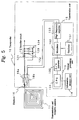
- FIG. 5 is a block diagram showing electric circuits of the transponder 10.
- symbol 10 shows the transponder, which is configured of a transmission and reception antenna 11, a rectifier circuit 12, a central processing unit 13, an information memory unit 14, a transmission unit 15, and a duplexer 16.
- the rectifier circuit 12 is configured of diodes 121 and 122, a capacitor 123, and a resister 124, and forms a known full-wave rectifier circuit.
- the transmission and reception antenna 11 is connected to the input side of this rectifier circuit 12 through the duplexer 16, and this rectifier circuit 12 outputs rectified current as a driving power supply of the central processing unit 13, information memory unit 14, and transmission unit 15 by rectifying high-frequency current, induced in the transmission and reception antenna 11, and converting the induced current into direct current.
- the central processing unit 13 is configured of a known CPU 131, and a digital/analog (hereinafter, this is called D/A) converter 132.
- D/A digital/analog
- the CPU 131 reads an ID code or identification information inherent in each transponder, which is stored in the information memory unit 14, and converts this digital data into analog data through the D/A converter 132 to output to the transmission unit 15.
- the transmission unit 15 is configured of an oscillator 151, a modulator 152 and a high-frequency amplifier 153, and modulates a carrier wave, which is generated by the oscillator 151 and has a frequency of, for example, 300 MHz, in the modulator 152 on the basis of a signal inputted from the central processing unit 13 to supply this modulated carrier wave to the transmission and reception antenna 11 through the high-frequency amplifier 153 and duplexer 16.
- the duplexer 16 is configured of a low-pass filter 16a and a high-pass filter 16b; the low-pass filter 16a is connected between the transmission and reception antenna 11 and rectifier circuit 12, and the high-pass filter 16b is connected between the transmission and reception antenna 11 and high-frequency amplifier 153.
- Respective terminals 2A through 2D are provided not only in each of areas (E A through E C ) in a predetermined rage, where fenders 1 that are objects to be managed are installed, but also in a ship S embarking fenders 1 that are object to be managed.
- Each terminal reads a ID code by accessing a transponder 10 mounted in the fender 1 and transfers historical information and the ID code in a lot as individual update information of the fender to the control system 4 by an operator inputting the historical information of this fender 1, regarding use, at that time such as installed places, installed periods, contents of repair, repaired locations, a storage location, and a storage period.
- a communication network such as the Internet, an ordinary telephone line, or a communication satellite is used.
- Figure 6 is a block diagram showing electric circuits of the terminal 2 (2A-2D).
- symbol 2 shows the terminal, which is configured of a scan unit 20 and a device body 30.
- the scan unit 20 is composed of a reception antenna 21, a reception unit 22, a central processing unit 23, a keyboard 24, a display unit 25, a transmission unit 26, a transmission antenna 27, and an interface unit 28 for data transfer with the device body 30 in order to improve portability and operatability.
- the scan unit 20 is formed in, for example, a hand-held unit as shown in Figure 7.
- the scan unit 20 is built in a pistol-shaped case 8,and the reception antenna 21 and transmission antenna 27 are installed in an end portion of the case 8; the keyboard 24 and display unit 25 are installed on the upper surface of the case 8.
- a battery or the like which is not shown, is used as a power supply.
- the scan unit 20 in this embodiment is a unit that receives an ID code transmitted from a transponder 10 by receiving an electromagnetic wave having a second frequency while radiating an electromagnetic wave having a first frequency to the transponder 10 as described later.
- the reception unit 22 in the scan unit 20 is configured by a receiver 221 and an analog/digital (hereinafter, this is called A/D) converter 222.
- the input side of the receiver 221 is connected to the reception antenna 21.
- the reception unit 22 receives and detects a 300-MHz high-frequency wave and then outputs the detected output to the central processing unit 23 through the A/D converter 222.
- the central processing unit 23 is configured of a known CPU 231 and memory 232, and not only stores information inputted from the reception unit 22 in the memory 232, but also displays the information on the display unit 25 on the basis of an input command from the keyboard 24. Furthermore, the central processing unit 23 not only stores the historical information of a fender 1, inputted from the keyboard 24, in the memory 232 in a one-to-one correspondence between the historical information and the ID code read, but also transfers the information stored in the memory 232 to the device body 30 through the interface unit 28 on the basis of the input command from the keyboard 24.
- a transmission unit 26 is configured of a transmitter 261, and the transmitter 261 outputs a high-frequency signal of, for example, 100-300 KHz to the transmission antenna 27 on the basis of a control signal from the CPU 231.
- the device body 30 is configured of an interface unit 31, a central processing unit 32, a communication controller 33, a keyboard 34, a display unit 35 and memory unit 36.
- the interface unit 31 is used when the information stored in the scan unit 20 is transferred to the device body 30 and configured of RS232c or infrared communication connection such as IRDA; and it has components similar to those of the interface unit 28 in the scan unit 20.
- the central processing unit 32 is configured of a known CPU or the like, and receives information from the scan unit 20 through the interface unit 31 on the basis of a command, inputted by the keyboard 34, to store this information in the memory unit 36. In addition, the central processing unit 32 not only updates the information stored in the memory unit 36, but also generates individual update information in regard to an updated part to transmit this information to the control system 4 through the communication controller 33 if the information inputted from the scan unit 20 is different from the information stored in the memory unit 36.
- the individual update information is made up of a serial number, the historical information updated, or the like for the fender 1 which is an object to be managed.
- the central processing unit 32 converts the ID code of the transponder, which is transferred from the scan unit 20, into the serial number on the basis of a corresponding table which is beforehand stored in the memory unit 36.
- the ID code of the transponder 10 and the serial number of the fender 1 having this transponder 10 are listed in a one-to-one correspondence between them. Even if a plurality of transponders 10 are mounted in a fender 1, it is possible to easily extract the serial number of the fender 1 having these transponders 10.
- the communication controller 33 performs information transfer with the control system 4 through a communication network 6 (6A-6D) such as the internet, ordinary telephone lines, wireless communication, and communication satellite.
- a communication network 6 (6A-6D) such as the internet, ordinary telephone lines, wireless communication, and communication satellite.
- the display unit 35 is configured of a monitor, connected to the central processing unit 32, or the like, and is used for displaying a processing information, processed in the central processing unit 32, and a memory information stored in the memory unit 36.
- the control system 4 is configured of a communication controller 41, a first memory unit 42, a second memory unit 43, a third memory unit 44, a central processing unit 45, a keyboard 46, and a display unit 47.
- the communication controller 41 similarly to that in the terminal 2, performs information transfer with the terminal 2 through the communication network 6 (6A-6D) such as the internet, ordinary telephone lines, or communication satellite.
- the communication network 6 (6A-6D) such as the internet, ordinary telephone lines, or communication satellite.
- Manufacturing information of each fender 1 is stored in the first memory unit 42. As shown in Figure 9, for example, rated dimensions, initial internal pressure, a model, cover structure, a manufacturing date, a customer name, a test report, manufacturing specifications, and remarks, which are corresponding to a serial number, are stored as the manufacturing information. Furthermore, manufacturing drawings such as an assembly drawing, used in manufacturing of the fender 1, are stored with corresponding to the serial number.
- the second memory unit 43 stores historical information of each fender 1.
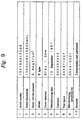
- the historical information an initial installation date, a initial installed place, use records, check and inspection records, repair records, remarks, and the like, which are corresponding to the serial number, are stored as shown in, for example, Figure 10.
- the third memory unit 44 stores a plurality of data of maps of all the installation areas E A through E C , where the fenders 1 are installed, for example, maps, which are drawn over from wide ranges to narrow rages every area, and aerial photographs.
- the central processing unit 45 is configured of a known CPU or the like.
- the central processing unit 45 receives the individual update information, which is transferred from the terminal 2, through the communication controller 41, and performs update processing of the historical information stored in the first memory unit 42. Furthermore, the central processing unit 45 displays the manufacturing information, historical information, or map of the installed place of the fender 1 designated by a serial number on the basis of an operator's instruction (command), inputted with the keyboard 46, on the display unit 47. Furthermore, the central processing unit 45 performs processing of correction and addition of the stored information according to an operator's command input from the keyboard.
- manufacturing information of the fenders 1 that are objects to be managed is stored in the control system 4 at the time of operation start.
- the information ad data can be inputted by the control system 4 itself, or can be stored by transferring the information and data, inputted in the terminal 2, to the control system 4.
- the corresponding table described above is stored in each terminal 2.
- the fender 1 is newly supplemented or moved to another installed place after the operation starts, the information stored in the control system 4 is added or updated. In addition, if the fender 1 is newly supplemented or annulled, it is necessary to update also the corresponding table in each terminal 2.
- the ID code of the transponder 10 mounted in the fender 1 that is an object whose information is to be updated is read by using only the scan unit 20 in the terminal 2. After historical information is inputted, this information is transferred to the device body 30.
- the distance between the scan unit 20 and transponder 10 is set within predetermined distance, and a read command is inputted from the keyboard 24 of the scan unit 20.
- the transmitter 26 is driven on the basis of an operating program in the CPU 231 in the scan unit 20, and the high-frequency signal of the first frequency or the high-frequency signal of 100-300 KHz is radiated from the transmission antenna 27.
- This electromagnetic wave is inputted to the transmission and reception antenna 11 of the transponder 10, and high-frequency current is induced in the transmission and reception antenna 11.
- the high-frequency current induced in the transmission and reception antenna 11 is rectified by the rectifier circuit 12 to supply electric power to the central processing unit 13, information memory unit 14, and transmission unit 15 inside the transponder 10.
- the central processing unit 13 to which the electric power is supplied while receiving the electromagnetic wave transmit from the scan unit 20, performs information transmission processing, programmed beforehand.
- the central processing unit 13 outputs the ID code, stored in the information memory unit 14, to the transmission unit 15.
- the transmission unit 15 modulates a carrier wave on the basis of this ID code, and supplies the modulated carrier wave or a high-frequency signal to the transmission and reception antenna 11.
- an electromagnetic wave of the second frequency or an electromagnetic wave having the frequency of 300 MHz is radiated from the transmission and reception antenna 11.
- the scan unit 20 receives the electromagnetic wave of 300 MHz, which is radiated from the transponder 10, by the reception unit 22 through the reception antenna 21, and the reception unit 22 converts the received ID code into digital data, and transmits the digital data to the central processing unit 23.
- the central processing unit 23 not only displays the ID code, which is based on the inputted digital data, on the display unit 25, but also stores the ID code in the memory 232.
- a operator inputs the historical information of the fender 1, from which the ID code is read, at that time, for example, the historical information such as an installed place and an installed period after change by operating the keyboard 24 of the scan unit 20.
- the central processing unit 23 of the scan unit 20 stores the historical information in the memory 232 which is associated with the ID code previously read. If the historical information of plural fender 1 is updated, operation described above can be repeated.
- the operator brings the scan unit 20 back to the installed place of the device body 30, and transfers the information, stored in the memory 232 of the scan unit 20, to the device body 30.
- the central processing unit 32 of the device body 30 not only updates the information stored in the memory unit 36, but also generates the individual update information, described above, on a part updated, and transmits this information to the control system 4 through the communication controller 33 if the information transferred from the scan unit 20 is different from the information stored in the memory unit 36.
- control system 4 which receives the individual update information, updates the information stored.
- the control system 4 which receives the individual update information, updates the information stored.
- the manufacturing information including the manufacturing drawings and the historical information of a specific fender, or to see maps or aerial photographs of an area where the installed place is included, the operator can display this information on the display unit 47 by inputting a command from the keyboard 46.
- an installation state of the fender 1 in the area designated by the operator is displayed by displaying the installed place of the fender 1 with superimposing a symbol and its serial number on a map or an aerial photograph of the designated area.
- this management system performs information transfer between the terminal 2 and control system 4 through the communication network 6, it is possible to update management information in real time without depending on distance between these installed places.
- an ID code inherent in each transponder 10 is stored in the information memory unit 14 of the transponder 10 mounted in the fender 1, and the ID code is converted into a serial number of the fender 1 by the terminal 2 having read this, and thereafter the fender is managed with being identified with the serial number. Therefore, it is possible to easily perform association with manufacturing information.
- the transponder 10 is mounted in the fender 1, and an ID code is automatically read by accessing the transponder 10; each fender 1 is designated by this ID code. Hence, it is possible to not only simplify management work, but also prevent an artificial error on management.
- an electromagnetic wave radiated from the scan unit 20 is converted into electrical energy in the transponder 10, and the transponder 10 operates by means of this electrical energy. Therefore, the transponder 10 can be semipermanently operated, and hence it is possible to simplify the maintenance of the transponder 10.
- the system configuration of the second embodiment is almost similar to the above-mentioned first embodiment.
- a difference between the first and second embodiments is that, in the second embodiment, the fender 1 itself has the historical information of the fender 1 by making the transponder 10 have a function of writing information to the information memory unit 14, and that an ID code is converted into a serial number in the control system 4 by making the control system 4 have a corresponding table.
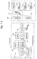
- FIG 11 is a block diagram showing electric circuits of the transponder 10 in the second embodiment.
- the same symbols are assigned to the same components in the first embodiment, and their description is omitted.
- the difference between the first and second embodiments is that a detection unit 17 is provided in the transponder 10, and the information memory unit 14 is configured of nonvolatile memory, which is readable and writable, such as EEPROM; the central processing unit 13 has a function of writing information to the information memory unit 14.
- the detection unit 17 is configured of a diode 171 and an A/D converter 172, the anode of the diode 171 is connected to the reception antenna 11, and the cathode is connected to the CPU 131 of the central processing unit 13 through the A/D converter.
- the information memory unit 14 is configured of semiconductor memory such as EEPROM connected to the CPU 131, and a ID code inherent in the transponder 10 is stored beforehand in this information memory unit 14.
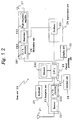
- Figure 12 is a block diagram showing electric circuits of the scan unit 20 in the terminal 2.
- the same symbols are assigned to the same components in the first embodiment, and their description is omitted.
- a difference between the first and second embodiments is that, in the second embodiment, historical information inputted from the keyboard can be transmitted to the transponder 10 by providing a modulation unit 29 in the scan unit 20.
- the modulation unit 29 is configured of a D/A converter 291, a modulator 292 and a high-frequency amplifier 293, and the input side of the D/A converter 291 is connected to the CPU 231 in the central processing unit 23; the output side is connected to the modulator 292.
- the modulator 292 receives a carrier wave from the transmission unit 26, and modulates this to supply this to the high-frequency amplifier 293.
- the high-frequency amplifier 293 amplifies the inputted high-frequency signal and outputs the signal to the transmission antenna 27.
- the device body 30 in the terminal 2 does not store an ID code of the transponder 10 and a corresponding table where the serial number of the fender 1 equipped with the transponder 10 is listed by associating the serial number with the ID code. Nevertheless, the control system 4 stores the corresponding table and converts the ID code into the serial number.
- the ID code of the transponder 10 mounted in the fender 1 that is a object whose information is to be updated, is read by using only the scan unit 20 in the terminal 2. Furthermore, historical information to be added is inputted. After this operation, by inputting an information write command from the keyboard 24 of the scan unit 20, the historical information of the fender 1, which is inputted to the scan unit 20, is additionally written in the information memory unit 14 of the transponder 10. Thereby, it is possible to hold the historical information of the fender 1 on the fender itself
- an ID code stored in the memory 232 of the scan unit 20, and historical information corresponding to this are transferred to the device body 30.
- the central processing unit 32 in the device body 30 not only updates the information stored in the memory unit 36, but also generates the individual update information, described above, on a part updated, and transmits this individual update information to the control system 4 through the communication controller 33 if the information transferred from the scan unit 20 is different from the information stored in the memory unit 36.
- the central processing unit 32 generates the individual update information including the ID code of the transponder 10 and historical information corresponding to this and transmits the individual update information.
- the control system 4 which receives this individual update information, converts the ID code into a serial number on the basis of the corresponding table, and thereafter updates the stored information on the basis of this serial number.
- the operator can display this information on the display unit 47 by inputting a command from the keyboard 46.
- the second embodiment similarly to the first embodiment, it is possible to not only exactly manage the fender 1 that is an object to be managed, but also allow the information memory unit 14 of the transponder 10 to hold the historical information of the fender 1. Therefore, it is possible to easily know the historical information of the fender 1 without using any control system 4.
- control system 4 By making the control system 4 hold the corresponding table, it is possible to reduce the load of processing in the terminal 2, and hence it is possible to perform downsizing and cost reduction of the terminal.
- a fender 1 is managed with making a serial number a reference by converting an ID code into the serial number of the fender 1 on the basis of the ID code stored beforehand in a transponder 10.
- conversion processing using a corresponding table is omitted by storing a serial number of a fender 1, which is an object to be mounted, in a transponder 10 beforehand. This method, however, requires work of writing the serial number into the transponder 10.
- a fender 1 can be also managed by using an ID code in a transponder 10 in the control system 4 without using any corresponding table.
- this method has a demerit of becoming complicated in many cases.
- the terminal 2 is configured of the detachable scan unit 20 and the device body 30, a terminal 2 can be configured by integrating the scan unit 20 and device body 30.
- the management system is a system managing fenders 1, which are installed in a plurality of areas (E A -A C ), in a lot.
- the management system can be a system managing a plurality of fenders 1 existing in only one area. In this case, for example, as shown in Figure 13, it is possible to simplify the configuration and realize this system by deleting the device body 30 of the terminal 2 and installing a control system 4', which is comprising an interface unit 48 with the scan unit 20, in the area.
- a pneumatic fender is exemplified, it goes without saying that the present invention can be applied to a rubber fender or a foam fender 60 shown in Figure 15, and similar effects can be obtained. Since foam material 61 is filled in the foam fender 60 shown in Figure 15, a position ,where a transponder 10 is mounted, can be comparatively freely selected. However, in order to adequately perform communication by an electromagnetic wave, it is preferable to install the transponder 10 near to a skin 62.
- a transponder is mounted in a fender 1 that is an object to be managed, and an ID code is read by accessing the transponder in the fender 1 with terminals 2A through 2D, one or more of which are provided in each of areas that are objects to be managed; individual update information including historical information, which shows installed places and installed periods of the fender 1, and the ID code is transferred to the control system 4 through communication networks 6A through 6D.
- the control system 4 not only stores manufacturing information and historical information of all the fenders 1 that are objects to be managed, but also updates the historical information on the basis of the individual update information received from the terminal 2 to display the manufacturing information and historical information of a specific fender 1 designated by an operator.
Abstract
Description
- The present invention relates to a fender, which is used as cushioning material mainly at the time of a ship being moored, and a management system thereof.
- Conventionally, fenders are used for buffering shock arising in a ship, a quay, or ships when the ship comes alongside a structure such as the quay or the ship comes alongside another ship on the sea.
- A fender is classified according to material buffering shock: a rubber fender buffering shock with rubber; a pneumatic fender buffering shock with air; a foam fender buffering shock with foam material; or the like. In addition, the fender is classified according to usage: a fixed fender used with being fixed with bolts to a structure such as a quay; and a floating fender used with being floating on the sea and bred with a chain or the like to a quay or a ship.
- Owners of these fenders are various, for example, port-related groups, ship-holding companies, rental companies of fenders and oil companies, and there are many fender manufactures in the world.
- Therefore, various types of fenders are intermixed in the same port. In particular, since the floating fenders are easily detached, the floating fenders are resold or borrowed and lent, are carried with being embarked on ships, or are used with being passed around many ships. Therefore, the floating fenders can not stay at a fixed location, but can move in the whole world in many cases.
- In addition, since the fenders are expensive, the fenders are used for the long time such as more than ten years, and are used after repair in case of slight damages.
- The fenders bear an important part in ships safely coming alongside quays and ships. The ships and quays are damaged if the fenders do not play the part, and hence it can cause serious accidents.
- Therefore, for the holding companies and users of the fenders, it is very important to identify each fender and recognize manufacturing items such as a manufacturing date and a manufacturing place, specifications and structure, characteristics such as buffering capability, information regarding history such as repair and used places of each fender in real time, and to manage many fenders so as to use only the normal fenders in any time.
- Nevertheless, it has been not easy to manage the fenders in a location where various fenders are intermixed as described above, and in particular, it was further difficult to manage the floating fenders used over the world with being moved.
- An object of the present invention is in consideration of the above problems to provide a fender and a fender management system that make it possible to easily manage the fenders installed in being dispersed.
- In order to attain the above object, the present invention comprises information memory means for storing predetermined information, and information read means for reading information stored in the information memory means, and a fender comprises a transponder that can access the information read means by wireless. In addition, a fender management system is configured, the system comprising: this fender; a terminal which is accessing the information memory means of the transponder, provided in the fender, by wireless; a control system that can communicate with this terminal, and stores information inherent in each fender, which is obtained through the terminal, with making the information correspond to each fender; and a computer that can communicate with the control system. The control system reads information from the information memory means of a transponder through the terminal, reads information of a fender stored in the computer by communicating with the computer, receives information inherent in each fender from the computer, and manages fenders, installed in a specific area, a wide area, or a plurality of remote areas, on the basis of this information above.
- It is possible that the information memory means of a transponder includes information such as identification information inherent in each fender for identifying the fender, identification information inherent in each transponder for identifying the transponder mounted in a fender, and manufacturing information, historical information, and characteristics of the fender.
- In addition, in order to manage in a specific area, a system comprising the fender, ad a terminal receiving and transmitting information by communicating with a transponder, provided in the fender, by wireless is configured, and the terminal comprises: information memory means for storing information regarding the fender that is an object to be managed; reception means for receiving information transmitted from the transponder; information update means for updating information, stored in the information memory means, on the basis of this information received; and information display means for displaying information of the fender designated by an operator.
- Furthermore, a system to which a control system having large information memory capacity is added is configured so that the system can receive and transmit information between the transponder and control system through the terminal, and can manage plenty of information for many fenders by using the control system.
- According to the management system, a transponder is mounted in a fender, and hence it is possible to automatically read the predetermined information stored in the information memory means by accessing the transponder, and to manage each fender by using this information.
- In addition, even if a location is apart from a fender in some extent, it is possible to access a transponder, to simplify management work, and to prevent an artificial human error on management.
- Furthermore, by providing information write means for being capable of accessing a transponder by wireless and for writing information to the information memory means of the transponder, a fender itself can hold unique information relating to the fender.
- In addition, a transponder comprises: reception means for receiving an electromagnetic wave having a first frequency; energy conversion means for converting the energy of the electromagnetic wave, received by the reception means, into electric energy; and transmission means for transmitting information, read from the information memory means by the information read means, by an electromagnetic wave having a second frequency. By making the transponder operate by electric energy obtained from the energy conversion means, it becomes possible for the transponder to semipermanently operate and to simplify the maintenance of the transponder.
- Furthermore, as a concrete system configuration, at least one transponder, storing identification information inherent in a fender, is mounted in the fender that is an object to be managed. The control system stores information inherent in each fender that is an object to be managed, for example, manufacturing information such as rated dimensions, an initial internal pressure, a manufacturing date, and a customer name, and, for example, historical information such as an initial installation date, an installed period, subsequent installed places and installed periods, and check, inspection, and repair records. This information can be displayed by designating a specific fender.
- Furthermore, if the installed place or the like of a fender is changes, the management system reads identification information by accessing the transponder of the fender with a terminal, and updates the historical information stored in the control system since the terminal generates the individual update information including this historical information and identification information by inputting to the terminal the historical information to be added. Thereby, it is possible to grasp information regarding an individual fender, to easily perform real-time management, and to prevent an artificial error on the management.
- In addition, since necessary information of each fender is stored in the control system by locating a terminal in an area where fenders, which are objects to be managed, are installed and providing at least one control system according to necessity, it is possible to grasp historical data such as installed places and installed periods of the fenders immediately and exactly.
- Furthermore, by performing information transfer between the control system and computer or between the terminal and control system through a communication network such as telephone lines, internets, wireless communications, and satellite communications, it is possible to update management information in real time without depending on distance between these installed places.
- In addition, if the information memory means of a transponder stores identification information inherent in the transponder such as an ID code inherent in each transponder, the terminal or control system converts this ID code into a serial number of the fender by using a corresponding table, and generates individual update information including this serial number and historical information; manages information by using the serial number as the identification information of the fender. Thereby, it is possible to easily associate each fender with manufacturing information thereof.
- Furthermore, by storing manufacturing drawings of each fender in manufacturing information memory means of the control system, it is possible to easily repair the fender on the basis of manufacturing drawings when urgent repair is necessary.
- In addition, by operator's command input, it is possible to grasp the location of each fender at the time of maintenance or the like by displaying a map or a photograph of the installed place and its vicinity of the installed place of an arbitrary fender on the basis of the historical information of the fender designated in the control system.
- Furthermore, by operator's command input, it is possible to easily perform movement plan such as the change of the installed place of a fender by displaying the installation state of the fender in a designated arbitrary area such as installed places, the number of fenders, kinds of the fenders, which are installed, on the basis of the historical information of the fenders in the control system.
-
- Figure 1 is a block diagram showing a fender management system in a first embodiment of the present invention; Figure 2 is an outside view showing a fender in the first embodiment of the present invention; Figure 3 is a partial cross-sectional view showing a mounting position of a transponder in the fender in the first embodiment of the present invention; Figure 4 is a block diagram for explaining contact areas and noncontact areas of the fender in the first embodiment of the present invention; Figure 5 is a block diagram showing electric circuits of the transponder in the first embodiment of the present invention; Figure 6 is a block diagram showing electric circuits of a terminal in the first embodiment of the present invention; Figure 7 is an outside view showing a scan unit in the first embodiment of the present invention; Figure 8 is a block diagram showing electric circuits of a control system in the first embodiment of the present invention; Figure 9 is a drawing for explaining the contents of manufacturing information in the first embodiment of the present invention; Figure 10 is a drawing for explaining the contents of historical information in the first embodiment of the present invention; Figure 11 is a block diagram showing electric circuits of a transponder in a second embodiment of the present invention; Figure 12 is a block diagram showing electric circuits of a scan unit in the second embodiment of the present invention; Figure 13 is a block diagram showing electric circuits of a control system in another embodiment; Figure 14 is a block diagram showing a fender management system in another embodiment; and Figure 15 is a partially broken side view showing a foam fender.
-
- Hereinafter, an embodiment of the present invention will be described with reference to drawings.
- Figure 1 is a block diagram showing a fender management system in a first embodiment of the present invention. In Figure 1,
symbols 1's (1A1-1An, 1B1-1Bn, 1C1-1Cn, and 1D1-1Dn) denote pneumatic fenders (hereinafter, these are called fenders) that are objects to be managed, symbols 2A through 2D denote terminals,symbol 4 denotes a control system, and symbols 6A through 6D denote communication networks. - The
fender 1 is used as cushioning material for a ship or the like by being fixed in an underwater structure such as a quay and a bridge pier or being floated on the surface of the water. For example, as shown in Figures 2 through 4, thefender 1 has a barrel-like shape obtained by sealing both ends of a rubber tube that is 3-4 m long and 1-2 m in diameter, and has a filler hole 1a of air in an end, and is filled with air of the predetermined internal pressure through this filler hole 1a. Furthermore, at least onetransponder 10 accessible by an electromagnetic wave is provided in the vicinity of the filler hole 1a. - Here, in order to reduce shock to the
transponder 10 and prevent damage of thetransponder 10, the inside or internal surface of a skin 1b made of the rubber tube is preferable as a mounting position of thetransponder 10. In this embodiment, thetransponder 10 is installed near by a bead ring 1d supporting cord tension of a rubber-coated cord layer 1c embedded in the skin 1b as shown in Figure 3. In addition, if the contact areas, where directly contact to a ship or quay at the time of use, and noncontact areas are clearly separated as the barrel-shaped fender 1 in this embodiment (refer to Figure 4), it is preferable to provide thetransponder 10 in the noncontact area in order to reduce shock to and prevent damage of thetransponder 10. - Figure 5 is a block diagram showing electric circuits of the
transponder 10. In Figure 5,symbol 10 shows the transponder, which is configured of a transmission andreception antenna 11, arectifier circuit 12, acentral processing unit 13, aninformation memory unit 14, atransmission unit 15, and aduplexer 16. - The
rectifier circuit 12 is configured ofdiodes capacitor 123, and aresister 124, and forms a known full-wave rectifier circuit. The transmission andreception antenna 11 is connected to the input side of thisrectifier circuit 12 through theduplexer 16, and thisrectifier circuit 12 outputs rectified current as a driving power supply of thecentral processing unit 13,information memory unit 14, andtransmission unit 15 by rectifying high-frequency current, induced in the transmission andreception antenna 11, and converting the induced current into direct current. - The
central processing unit 13 is configured of a knownCPU 131, and a digital/analog (hereinafter, this is called D/A)converter 132. When electric power is supplied to theCPU 131 and theCPU 131 becomes operable, theCPU 131 reads an ID code or identification information inherent in each transponder, which is stored in theinformation memory unit 14, and converts this digital data into analog data through the D/A converter 132 to output to thetransmission unit 15. - The
transmission unit 15 is configured of anoscillator 151, amodulator 152 and a high-frequency amplifier 153, and modulates a carrier wave, which is generated by theoscillator 151 and has a frequency of, for example, 300 MHz, in themodulator 152 on the basis of a signal inputted from thecentral processing unit 13 to supply this modulated carrier wave to the transmission andreception antenna 11 through the high-frequency amplifier 153 andduplexer 16. - The
duplexer 16 is configured of a low-pass filter 16a and a high-pass filter 16b; the low-pass filter 16a is connected between the transmission andreception antenna 11 andrectifier circuit 12, and the high-pass filter 16b is connected between the transmission andreception antenna 11 and high-frequency amplifier 153. - Respective terminals 2A through 2D are provided not only in each of areas (EA through EC) in a predetermined rage, where
fenders 1 that are objects to be managed are installed, but also in a shipS embarking fenders 1 that are object to be managed. Each terminal reads a ID code by accessing atransponder 10 mounted in thefender 1 and transfers historical information and the ID code in a lot as individual update information of the fender to thecontrol system 4 by an operator inputting the historical information of thisfender 1, regarding use, at that time such as installed places, installed periods, contents of repair, repaired locations, a storage location, and a storage period. When individual update information is transferred, a communication network such as the Internet, an ordinary telephone line, or a communication satellite is used. - Figure 6 is a block diagram showing electric circuits of the terminal 2 (2A-2D). In Figure 6,
symbol 2 shows the terminal, which is configured of ascan unit 20 and adevice body 30. - The
scan unit 20, as shown in Figure 6, is composed of areception antenna 21, areception unit 22, acentral processing unit 23, akeyboard 24, adisplay unit 25, atransmission unit 26, atransmission antenna 27, and aninterface unit 28 for data transfer with thedevice body 30 in order to improve portability and operatability. Thescan unit 20 is formed in, for example, a hand-held unit as shown in Figure 7. In Figure 7, thescan unit 20 is built in a pistol-shapedcase 8,and thereception antenna 21 andtransmission antenna 27 are installed in an end portion of thecase 8; thekeyboard 24 anddisplay unit 25 are installed on the upper surface of thecase 8. In this case, a battery or the like, which is not shown, is used as a power supply. - Here, the
scan unit 20 in this embodiment is a unit that receives an ID code transmitted from atransponder 10 by receiving an electromagnetic wave having a second frequency while radiating an electromagnetic wave having a first frequency to thetransponder 10 as described later. - In addition, the
reception unit 22 in thescan unit 20 is configured by areceiver 221 and an analog/digital (hereinafter, this is called A/D)converter 222. The input side of thereceiver 221 is connected to thereception antenna 21. Thereception unit 22 receives and detects a 300-MHz high-frequency wave and then outputs the detected output to thecentral processing unit 23 through the A/D converter 222. - The
central processing unit 23 is configured of a knownCPU 231 andmemory 232, and not only stores information inputted from thereception unit 22 in thememory 232, but also displays the information on thedisplay unit 25 on the basis of an input command from thekeyboard 24. Furthermore, thecentral processing unit 23 not only stores the historical information of afender 1, inputted from thekeyboard 24, in thememory 232 in a one-to-one correspondence between the historical information and the ID code read, but also transfers the information stored in thememory 232 to thedevice body 30 through theinterface unit 28 on the basis of the input command from thekeyboard 24. - In addition, a
transmission unit 26 is configured of atransmitter 261, and thetransmitter 261 outputs a high-frequency signal of, for example, 100-300 KHz to thetransmission antenna 27 on the basis of a control signal from theCPU 231. - The
device body 30 is configured of an interface unit 31, acentral processing unit 32, acommunication controller 33, akeyboard 34, adisplay unit 35 andmemory unit 36. - The interface unit 31 is used when the information stored in the
scan unit 20 is transferred to thedevice body 30 and configured of RS232c or infrared communication connection such as IRDA; and it has components similar to those of theinterface unit 28 in thescan unit 20. - The
central processing unit 32 is configured of a known CPU or the like, and receives information from thescan unit 20 through the interface unit 31 on the basis of a command, inputted by thekeyboard 34, to store this information in thememory unit 36. In addition, thecentral processing unit 32 not only updates the information stored in thememory unit 36, but also generates individual update information in regard to an updated part to transmit this information to thecontrol system 4 through thecommunication controller 33 if the information inputted from thescan unit 20 is different from the information stored in thememory unit 36. - The individual update information is made up of a serial number, the historical information updated, or the like for the
fender 1 which is an object to be managed. Thecentral processing unit 32 converts the ID code of the transponder, which is transferred from thescan unit 20, into the serial number on the basis of a corresponding table which is beforehand stored in thememory unit 36. - In the corresponding table, the ID code of the
transponder 10 and the serial number of thefender 1 having thistransponder 10 are listed in a one-to-one correspondence between them. Even if a plurality oftransponders 10 are mounted in afender 1, it is possible to easily extract the serial number of thefender 1 having thesetransponders 10. - The
communication controller 33 performs information transfer with thecontrol system 4 through a communication network 6 (6A-6D) such as the internet, ordinary telephone lines, wireless communication, and communication satellite. - The
display unit 35 is configured of a monitor, connected to thecentral processing unit 32, or the like, and is used for displaying a processing information, processed in thecentral processing unit 32, and a memory information stored in thememory unit 36. - The
control system 4, as shown in Figure 8, is configured of a communication controller 41, a first memory unit 42, asecond memory unit 43, athird memory unit 44, a central processing unit 45, a keyboard 46, and adisplay unit 47. - The communication controller 41, similarly to that in the
terminal 2, performs information transfer with theterminal 2 through the communication network 6 (6A-6D) such as the internet, ordinary telephone lines, or communication satellite. - Manufacturing information of each
fender 1 is stored in the first memory unit 42. As shown in Figure 9, for example, rated dimensions, initial internal pressure, a model, cover structure, a manufacturing date, a customer name, a test report, manufacturing specifications, and remarks, which are corresponding to a serial number, are stored as the manufacturing information. Furthermore, manufacturing drawings such as an assembly drawing, used in manufacturing of thefender 1, are stored with corresponding to the serial number. - The
second memory unit 43 stores historical information of eachfender 1. As the historical information, an initial installation date, a initial installed place, use records, check and inspection records, repair records, remarks, and the like, which are corresponding to the serial number, are stored as shown in, for example, Figure 10. - As the use records, installed places and installed periods, which are results of changes after the initial installation, are recorded. As the check and inspection records, implemented dates of checks and inspections and their results are recorded. In addition, as the repair records, implemented dates of repairs, repaired parts, are recorded.
- The
third memory unit 44 stores a plurality of data of maps of all the installation areas EA through EC, where thefenders 1 are installed, for example, maps, which are drawn over from wide ranges to narrow rages every area, and aerial photographs. - The central processing unit 45 is configured of a known CPU or the like. The central processing unit 45 receives the individual update information, which is transferred from the
terminal 2, through the communication controller 41, and performs update processing of the historical information stored in the first memory unit 42. Furthermore, the central processing unit 45 displays the manufacturing information, historical information, or map of the installed place of thefender 1 designated by a serial number on the basis of an operator's instruction (command), inputted with the keyboard 46, on thedisplay unit 47. Furthermore, the central processing unit 45 performs processing of correction and addition of the stored information according to an operator's command input from the keyboard. - Next, an operation method and operation of the management system having the above configuration will be described.
- When this management system is used, manufacturing information of the
fenders 1 that are objects to be managed, historical information at the time of operation start, and data such as maps and aerial photographs of an area where thefenders 1 are installed are stored in thecontrol system 4 at the time of operation start. The information ad data can be inputted by thecontrol system 4 itself, or can be stored by transferring the information and data, inputted in theterminal 2, to thecontrol system 4. Furthermore, the corresponding table described above is stored in eachterminal 2. - On the other hand, if the
fender 1 is newly supplemented or moved to another installed place after the operation starts, the information stored in thecontrol system 4 is added or updated. In addition, if thefender 1 is newly supplemented or annulled, it is necessary to update also the corresponding table in eachterminal 2. - If the historical information of the
fender 1 is updated in each of installed places EA-EC, the ID code of thetransponder 10 mounted in thefender 1 that is an object whose information is to be updated is read by using only thescan unit 20 in theterminal 2. After historical information is inputted, this information is transferred to thedevice body 30. - When the ID code of the
transponder 10 is read, the distance between thescan unit 20 andtransponder 10 is set within predetermined distance, and a read command is inputted from thekeyboard 24 of thescan unit 20. Thereby, thetransmitter 26 is driven on the basis of an operating program in theCPU 231 in thescan unit 20, and the high-frequency signal of the first frequency or the high-frequency signal of 100-300 KHz is radiated from thetransmission antenna 27. - This electromagnetic wave is inputted to the transmission and
reception antenna 11 of thetransponder 10, and high-frequency current is induced in the transmission andreception antenna 11. The high-frequency current induced in the transmission andreception antenna 11 is rectified by therectifier circuit 12 to supply electric power to thecentral processing unit 13,information memory unit 14, andtransmission unit 15 inside thetransponder 10. - Thereby, the
central processing unit 13, to which the electric power is supplied while receiving the electromagnetic wave transmit from thescan unit 20, performs information transmission processing, programmed beforehand. Thus, thecentral processing unit 13 outputs the ID code, stored in theinformation memory unit 14, to thetransmission unit 15. Thetransmission unit 15 modulates a carrier wave on the basis of this ID code, and supplies the modulated carrier wave or a high-frequency signal to the transmission andreception antenna 11. Thereby, an electromagnetic wave of the second frequency or an electromagnetic wave having the frequency of 300 MHz is radiated from the transmission andreception antenna 11. - The
scan unit 20 receives the electromagnetic wave of 300 MHz, which is radiated from thetransponder 10, by thereception unit 22 through thereception antenna 21, and thereception unit 22 converts the received ID code into digital data, and transmits the digital data to thecentral processing unit 23. - The
central processing unit 23 not only displays the ID code, which is based on the inputted digital data, on thedisplay unit 25, but also stores the ID code in thememory 232. - Next, a operator inputs the historical information of the
fender 1, from which the ID code is read, at that time, for example, the historical information such as an installed place and an installed period after change by operating thekeyboard 24 of thescan unit 20. - Thereby, the
central processing unit 23 of thescan unit 20 stores the historical information in thememory 232 which is associated with the ID code previously read. If the historical information ofplural fender 1 is updated, operation described above can be repeated. - After this, the operator brings the
scan unit 20 back to the installed place of thedevice body 30, and transfers the information, stored in thememory 232 of thescan unit 20, to thedevice body 30. Thereby, thecentral processing unit 32 of thedevice body 30 not only updates the information stored in thememory unit 36, but also generates the individual update information, described above, on a part updated, and transmits this information to thecontrol system 4 through thecommunication controller 33 if the information transferred from thescan unit 20 is different from the information stored in thememory unit 36. - Therefore, the
control system 4, which receives the individual update information, updates the information stored. In addition, if an operator wants to know the manufacturing information, including the manufacturing drawings and the historical information of a specific fender, or to see maps or aerial photographs of an area where the installed place is included, the operator can display this information on thedisplay unit 47 by inputting a command from the keyboard 46. - Furthermore, an installation state of the
fender 1 in the area designated by the operator is displayed by displaying the installed place of thefender 1 with superimposing a symbol and its serial number on a map or an aerial photograph of the designated area. - As described above, according to the first embodiment, it is possible to exactly manage the
fender 1 that is an object to be managed. - In addition, since this management system performs information transfer between the terminal 2 and
control system 4 through thecommunication network 6, it is possible to update management information in real time without depending on distance between these installed places. - Furthermore, an ID code inherent in each
transponder 10 is stored in theinformation memory unit 14 of thetransponder 10 mounted in thefender 1, and the ID code is converted into a serial number of thefender 1 by theterminal 2 having read this, and thereafter the fender is managed with being identified with the serial number. Therefore, it is possible to easily perform association with manufacturing information. - In addition, the
transponder 10 is mounted in thefender 1, and an ID code is automatically read by accessing thetransponder 10; eachfender 1 is designated by this ID code. Hence, it is possible to not only simplify management work, but also prevent an artificial error on management. - Furthermore, an electromagnetic wave radiated from the
scan unit 20 is converted into electrical energy in thetransponder 10, and thetransponder 10 operates by means of this electrical energy. Therefore, thetransponder 10 can be semipermanently operated, and hence it is possible to simplify the maintenance of thetransponder 10. - Moreover, since it is possible to display the manufacturing drawings of each
fender 1 by operator's designated input in thecontrol system 4, it is possible to repair thefender 1 on the basis of the manufacturing drawings displayed if urgent repair is necessary. In addition, since it is possible to display a map or a photograph of a installed place of anarbitrary fender 1 and its vicinity in thecontrol system 4 by operator's command input, it is possible to easily grasp the place of eachfender 1 at the time of maintenance or the like. - Furthermore, since it is possible to display an installation state of the
fenders 1 in an arbitrary area among areas EA through EC in thecontrol system 4 by operator's command input, it is possible to easily perform a movement plan such as change of a installed place of thefenders 1. - Next, a second embodiment of the present invention will be described.
- The system configuration of the second embodiment is almost similar to the above-mentioned first embodiment. A difference between the first and second embodiments is that, in the second embodiment, the
fender 1 itself has the historical information of thefender 1 by making thetransponder 10 have a function of writing information to theinformation memory unit 14, and that an ID code is converted into a serial number in thecontrol system 4 by making thecontrol system 4 have a corresponding table. - Hereinafter, the difference from the first embodiment will be described.
- Figure 11 is a block diagram showing electric circuits of the
transponder 10 in the second embodiment. In Figure 11, the same symbols are assigned to the same components in the first embodiment, and their description is omitted. In addition, the difference between the first and second embodiments is that a detection unit 17 is provided in thetransponder 10, and theinformation memory unit 14 is configured of nonvolatile memory, which is readable and writable, such as EEPROM; thecentral processing unit 13 has a function of writing information to theinformation memory unit 14. - Thus, the detection unit 17 is configured of a
diode 171 and an A/D converter 172, the anode of thediode 171 is connected to thereception antenna 11, and the cathode is connected to theCPU 131 of thecentral processing unit 13 through the A/D converter. - The
information memory unit 14 is configured of semiconductor memory such as EEPROM connected to theCPU 131, and a ID code inherent in thetransponder 10 is stored beforehand in thisinformation memory unit 14. - Figure 12 is a block diagram showing electric circuits of the
scan unit 20 in theterminal 2. In Figure 12, the same symbols are assigned to the same components in the first embodiment, and their description is omitted. In addition, a difference between the first and second embodiments is that, in the second embodiment, historical information inputted from the keyboard can be transmitted to thetransponder 10 by providing amodulation unit 29 in thescan unit 20. - Thus, the
modulation unit 29 is configured of a D/A converter 291, amodulator 292 and a high-frequency amplifier 293, and the input side of the D/A converter 291 is connected to theCPU 231 in thecentral processing unit 23; the output side is connected to themodulator 292. Themodulator 292 receives a carrier wave from thetransmission unit 26, and modulates this to supply this to the high-frequency amplifier 293. The high-frequency amplifier 293 amplifies the inputted high-frequency signal and outputs the signal to thetransmission antenna 27. - In addition, the
device body 30 in theterminal 2 does not store an ID code of thetransponder 10 and a corresponding table where the serial number of thefender 1 equipped with thetransponder 10 is listed by associating the serial number with the ID code. Nevertheless, thecontrol system 4 stores the corresponding table and converts the ID code into the serial number. - According to the configuration described above, when the historical information of a
fender 1 is updated in each of installed places EA through EC, first, the ID code of thetransponder 10 mounted in thefender 1 ,that is a object whose information is to be updated, is read by using only thescan unit 20 in theterminal 2. Furthermore, historical information to be added is inputted. After this operation, by inputting an information write command from thekeyboard 24 of thescan unit 20, the historical information of thefender 1, which is inputted to thescan unit 20, is additionally written in theinformation memory unit 14 of thetransponder 10. Thereby, it is possible to hold the historical information of thefender 1 on the fender itself - In addition, when an operator wants to know the historical information stored in the
information memory unit 14 of thetransponder 10, it is possible to display the historical information on thedisplay unit 25 of thescan unit 20 by receiving the historical information since the historical information, stored in theinformation memory unit 14, is transmitted from thetransponder 10 by transmitting an information read command from thescan unit 20 to thetransponder 10. - Next, similarly to the first embodiment, an ID code, stored in the
memory 232 of thescan unit 20, and historical information corresponding to this are transferred to thedevice body 30. - Thereby, the
central processing unit 32 in thedevice body 30 not only updates the information stored in thememory unit 36, but also generates the individual update information, described above, on a part updated, and transmits this individual update information to thecontrol system 4 through thecommunication controller 33 if the information transferred from thescan unit 20 is different from the information stored in thememory unit 36. - At this time, the
central processing unit 32 generates the individual update information including the ID code of thetransponder 10 and historical information corresponding to this and transmits the individual update information. - The
control system 4 ,which receives this individual update information, converts the ID code into a serial number on the basis of the corresponding table, and thereafter updates the stored information on the basis of this serial number. - In addition, if an operator wants to know the manufacturing information and historical information of a specific fender, or to see maps and aerial photographs of an area where the installed place is included, which is similarly to the first embodiment, the operator can display this information on the
display unit 47 by inputting a command from the keyboard 46. - As described above, according to the second embodiment, similarly to the first embodiment, it is possible to not only exactly manage the
fender 1 that is an object to be managed, but also allow theinformation memory unit 14 of thetransponder 10 to hold the historical information of thefender 1. Therefore, it is possible to easily know the historical information of thefender 1 without using anycontrol system 4. - In addition, by making the
control system 4 hold the corresponding table, it is possible to reduce the load of processing in theterminal 2, and hence it is possible to perform downsizing and cost reduction of the terminal. - In addition, in the first and second embodiments described above, a
fender 1 is managed with making a serial number a reference by converting an ID code into the serial number of thefender 1 on the basis of the ID code stored beforehand in atransponder 10. Alternatively, it can be performed that conversion processing using a corresponding table is omitted by storing a serial number of afender 1, which is an object to be mounted, in atransponder 10 beforehand. This method, however, requires work of writing the serial number into thetransponder 10. - In addition, a
fender 1 can be also managed by using an ID code in atransponder 10 in thecontrol system 4 without using any corresponding table. However, if two ormore transponders 10 are mounted in onefender 1, this method has a demerit of becoming complicated in many cases. - Furthermore, in the embodiments described above, although the
terminal 2 is configured of thedetachable scan unit 20 and thedevice body 30, aterminal 2 can be configured by integrating thescan unit 20 anddevice body 30. - Moreover, a pair of the
terminal 2 andcontrol system 4 can be also installed in each area where afender 1 is installed. Thus, in the first and second embodiments described above, the management system is asystem managing fenders 1, which are installed in a plurality of areas (EA-AC), in a lot. However, the present invention is not limited to this. The management system can be a system managing a plurality offenders 1 existing in only one area. In this case, for example, as shown in Figure 13, it is possible to simplify the configuration and realize this system by deleting thedevice body 30 of theterminal 2 and installing a control system 4', which is comprising aninterface unit 48 with thescan unit 20, in the area. - In addition, by expanding memory capacity of the
scan unit 20, it is also possible to manage afender 1 using only a terminal composed of only thescan unit 20 without using a control system. However, in this case, management information is limited in some measure. - Furthermore, as shown in Figure 14, it can be performed to communicate through the
communication network 6 between acomputer 50, which is installed in a manufacturing company or the like of afender 1 and stores manufacturing information of the fender, and thecontrol system 4 or 4', and to use information by transferring from thecomputer 50 the information necessary in thecontrol system 4 or 4'. - Moreover, it goes without saying that it can be also performed to install a plurality of
terminals 2 or a plurality ofcontrol systems 4 or 4' in a area and use these at the same time. - In addition, in the first and second embodiments, although a pneumatic fender is exemplified, it goes without saying that the present invention can be applied to a rubber fender or a foam fender 60 shown in Figure 15, and similar effects can be obtained. Since
foam material 61 is filled in the foam fender 60 shown in Figure 15, a position ,where atransponder 10 is mounted, can be comparatively freely selected. However, in order to adequately perform communication by an electromagnetic wave, it is preferable to install thetransponder 10 near to a skin 62. - The present invention can be embodied in other specific forms without departing from the spirit or essential characteristics thereof. The present embodiments are therefore to be considered in all respects as illustrative and not restrictive, the scope of the present invention being indicated by the appended claims rather than by the foregoing description and all changes which come within the meaning and rage of equivalency of the claims are therefore intended to be embraced therein.
- A transponder is mounted in a
fender 1 that is an object to be managed, and an ID code is read by accessing the transponder in thefender 1 with terminals 2A through 2D, one or more of which are provided in each of areas that are objects to be managed; individual update information including historical information, which shows installed places and installed periods of thefender 1, and the ID code is transferred to thecontrol system 4 through communication networks 6A through 6D. Thecontrol system 4 not only stores manufacturing information and historical information of all thefenders 1 that are objects to be managed, but also updates the historical information on the basis of the individual update information received from theterminal 2 to display the manufacturing information and historical information of aspecific fender 1 designated by an operator. Thereby, it is possible to manage each fender by using the information obtained by accessing the transponder. Hence, it is possible to not only prevent a human error on management, but also simplify management work since it is possible to access the transponder even from a position where is apart from the fender in some measure. Furthermore, it is possible to not only grasp the historical information such as the installed place and installed period of the fender immediately and exactly, but also update management information in real time without depending on distance between installed places. -
- 2A through 2D
- Terminal
- 4
- Control system
- 6A through 6D
- Communication network
- 1A1
- Fender
- S
- Ship
-
- 1
- Fender
- 1a
- Filler hole
- 10
- Transponder
-
- 1b
- Skin
- 1c
- Rubber-coated cord layer
- 10
- Transponder
- 1a
- Filler hole
- 1d
- Bead ring
-
- 1
- Fender
- 10
- Transponder
- 1a
- Filler hole
- #1
- Noncontact area
- #2
- Contact area
-
- 10
- Transponder
- 16
- Duplexer
- 12
- Rectifier circuit
- 11
- Transmission and reception antenna
- 132
- D/A converter
- 152
- Modulator
- 153
- High-frequency amplifier
- 14
- Information memory unit
- 13
- Central processing unit
- 151
- Oscillator
- 15
- Transmission unit
-
- 2
- Terminal
- 6
- Communication network
- 20
- Scan unit
- 30
- Device body
- 24
- Keyboard
- 22
- Reception unit
- 222
- D/A converter
- 261
- Transmitter
- 26
- Transmission unit
- 232
- Memory
- 25
- Display unit
- 28
- Interface unit
- 23
- Central processing unit
- 31
- Interface unit
- 32
- Central processing unit
- 33
- Communication controller
- 35
- Display unit
- 36
- Memory unit
- 34
- Keyboard
-
- 20
- Scan unit
- 25
- Display unit
- 24
- Keyboard
- 21
- Transmission antenna
- 21
- Reception antenna
-
- 4
- Control system
- 6
- Communication network
- 41
- Communication controller
- 45
- Central processing unit
- 47
- Display unit
- 42
- First memory unit
- 43
- Second memory unit
- 44
- Third memory unit
- 46
- Keyboard
-
- 1
- Serial number
- 2
- Rated dimensions
- 3
- Initial internal pressure
- 4
- Model
- 5
- Cover structure
- 6
- Manufacturing date
- 7
- Customer
- 8
- Test report
- 9
- Manufacturing specifications
- 10
- Remarks
-
- 1
- Serial number
- 2
- Initial installation date
- 3
- Initial installed place
- 4
- Use history
- 5
- Check and inspection record
- 6
- Repair record
- 7
- Miscellaneous
-
- 10
- Transponder
- 16
- Duplexer
- 12
- Rectifier circuit
- 17
- Detection unit
- 172
- A/D converter
- 11
- Transmission and reception antenna
- 132
- D/A converter
- 152
- Modulator
- 153
- High-frequency amplifier
- 14
- Information memory unit
- 13
- Central processing unit
- 151
- Oscillator
- 15
- Transmission unit
-
- 20
- Scan unit
- 24
- Keyboard
- 22
- Reception unit
- 221
- Receiver
- 222
- D/A converter
- 232
- Memory
- 23
- Central processing unit
- 28
- Interface unit
- 29
- Modulation unit
- 291
- D/A converter
- 292
- Modulator
- 293
- High-frequency amplifier
- 261
- Transmitter
- 26
- Transmission unit
- 25
- Display unit
-
- 20
- Scan unit
- 24
- Keyboard
- 22
- Reception unit
- 221
- Receiver
- 222
- D/A converter
- 261
- Transmitter
- 26
- Transmission unit
- 232
- Memory
- 25
- Display unit
- 28
- Interface unit
- 23
- Central processing unit
- 4'
- Control system
- 45
- Central processing unit
- 48
- Interface unit
- 47
- Display unit
- 42
- First memory unit
- 43
- Second memory unit
- 44
- Third memory unit
- 46
- Keyboard
-
- 6
- Communication network
- 50
- Computer
- 4 (4')
- Control system
- 1A1, 1A2, 1An
- Fender
- 2
- Terminal
-
- 60
- Foam fender
- 61
- Form material
- 62
- Skin
- 10
- Transponder
Claims (30)
- A fender comprising:information memory means for storing predetermined information;information read means for reading information stored in the information memory means; anda transponder that can access the information read means by wireless.
- The fender according to claim 1, wherein the said transponder comprises information write means for making it possible to access the said information memory means by wireless and writing information into the information memory means.
- The fender according to claim 1 or 2, wherein the said transponder comprises:reception means for receiving an electromagnetic wave having a first frequency;energy conversion means for converting energy of the electromagnetic wave, received by the reception means, into electric energy; andtransmission means for transmitting information, read from the information memory means by the said information read means, by a electromagnetic wave having a second frequency, wherein the transponder operates by electric energy obtained by the said energy conversion means.
- The fender according to claim 1, 2, or 3, wherein predetermined information stored in the said information memory means includes at least identification information, which is inherent in each fender, for identifying the fender.
- The fender according to claim 1, 2, or 3, wherein the predetermined information stored in the said information memory means includes at least identification information, which is inherent in each transponder, for identifying the transponder mounted in the fender.
- The fender according to any one of claims 1 through 5, wherein the said information includes manufacturing information and/or historical information of the fender.
- The fender according to any one of claims 1 through 6, wherein the fender is a floating fender floating on the water.
- The fender according to any one of claims 1 through 7, wherein the said fender is a fender comprising a skin having a predetermined thickness, and the transponder is provided inside a surface of the skin.
- The fender according to any one of claims 1 through 8, wherein the fender has a shape having a contact area, where is contacting to a shock object giving shock in use, and a noncontact area, where is not contacting to the shock object, and the transponder is provided in the said noncontact area.
- A fender management system comprising:a fender according to any one of claims 1 through 9; anda terminal, wherein the terminal comprising:information read means for accessing information memory means of a transponder provided in the said fender and reading information stored in the information memory means of the transponder; andat least information display means for displaying the information read from the information memory means of the transponder in the said fender.
- A fender management system comprising:a fender according to any one of claims 1 through 9;a terminal accessing information memory means of the transponder, provided in the fender, by wireless;a control system that can communicate with the terminal, and stores information inherent in each fender, which is obtained through the terminal and corresponding to each fender; anda computer that can communicate with the control system, wherein the said control system reads information from the information memory means of the said transponder through the said terminal; and wherein the said control system further reads information of the fender, which is stored in the said computer, by communicating with the said computer, receives information of each fender from the computer, and manages the fender on the basis of this information.
- The fender management system according to claim 11, wherein communication between the said control system and computer is performed through a communication network.
- A fender management system comprising a fender according to any one of claims 1 through 9, a terminal, and a control system, wherein the said terminal communicates with a transponder, provided in the fender, by wireless, and transfers information, which the transponder transmits, to the control system; wherein the said control system comprises:information memory means for storing information of the fender that is an object to be managed;reception means for receiving information, which the said transponder transmits, from the said terminal;information update means for updating information, which the information memory means stores, on the basis of the received information; andinformation display means for displaying information of a fender that an operator designates.
- The fender management system according to any one of claims 11 through 13, wherein communication between the said terminal and control system is performed through a communication network.
- The fender management system according to any one of claims 10 through 14, wherein the said terminal comprises information write means for writing information into information memory means of the said transponder.
- The fender management system according to any one of claims 11 through 14, wherein the information memory means of the said transponder stores at least identification information inherent in each fender; wherein the said terminal reads and transmits identification information inherent in each fender to a control system; and wherein the said control system stores information inherent in a fender, which is an object to be managed, in a one-to-one correspondence between the inherent information and the identification information.
- The fender management system according to any one of claims 11 through 14, wherein the information memory means of the said transponder stores at least identification information inherent in each transponder; wherein the said terminal has a corresponding table associating identification information inherent in each transponder with a serial number of a fender where the transponder is mounted, and conversion means for converting identification information inherent in a transponder into a serial number of a fender on the basis of the corresponding table, converts identification information inherent in a transponder, which is read from the transponder, into a serial number of a fender, and transmits the serial number to the said control system; and wherein the said control system stores information inherent in a fender in a one-to-one correspondence between and said serial number.
- The fender management system according to any one of claims 11 through 14, wherein the information memory means of a said transponder stores at least identification information inherent in each transponder; wherein the said terminal has a corresponding table associating identification information inherent in each transponder with a serial number of a fender in which the transponder is mounted, and conversion means for converting identification information inherent in a transponder into a serial number of a fender on the basis of the corresponding table, and stores information inherent in a fender in a one-tone correspondence between the inherent information and the said serial number.
- The fender management system according to claim 11 or 12, wherein the information, which the said computer stores, includes specifications, structure, characteristics, and manufacturing information of each fender.
- The fender management system according to any one of claims 11 through 14, wherein the said information of a fender includes manufacturing drawings.
- The fender management system according to any one of claims 11 through 14, wherein the said control system comprises installation state display means for displaying an installation state of fenders in a specific area where a operator designates.
- The fender management system according to any one of claims 11 through 14, wherein the said information of a fender includes an installed place of the fender, which is an object to be managed, and a map or a photograph of its vicinity; and wherein the said control system comprises installed place display means for displaying a installed place of a specific fender, which a operator designates, and a map or a photograph of its vicinity.
- A pneumatic fender that is used as cushioning material for a ship or the like with being fixed to an underwater structure or floated, comprising:information memory means for storing a predetermined information; information read means for reading information stored in the information memory means; and a transponder that can access the said information memory means by wireless.
- The pneumatic fender according to claim 23, wherein the said transponder comprises:reception means for receiving an electromagnetic wave having a first frequency;energy conversion means for converting energy of an electromagnetic wave, received by the reception means, into electric energy; andtransmission means for transmitting information, read from the information memory means by the said information read means, by an electromagnetic wave having a second frequency, wherein the transponder operates by electric energy obtained by the said energy conversion means.
- A management system of a pneumatic fender that is used as cushioning material for a ship or the like with being fixed to a underwater structure or floated, comprising:a plurality of pneumatic fenders comprising information memory means for storing at least identification information inherent in each pneumatic fender, information read means for reading information stored in the information memory means, and a transponder that can access the said information memory means by wireless;a plurality of terminals that can transfer information through a communication network with each other; andone or more control systems, wherein the said terminals comprises:identification information read means for accessing a transponder of the pneumatic fender and reading identification information;historical information input means for inputting historical information showing at least an installed place and an installed period of a pneumatic fender having the identification information at this time; andtransmission means for generating an individual update information, including the said identification information and historical information, every pneumatic fender and transmitting the individual update information through the said communication network; wherein the said control system comprises:manufacturing information memory means for storing manufacturing information of all the pneumatic fenders, which are objects to be managed, in a one-to-one correspondence between the manufacturing information and the said identification information;historical information memory means for storing historical information of all the pneumatic fenders, which are objects to be managed, in a one-to-one correspondence between the historical information and said the identification information;reception means for receiving the said individual update information from each terminal through a communication network;historical information update means for updating historical information, stored in the said historical information memory means, on the basis of individual update information received by the reception means; andinformation display means for displaying manufacturing information and historical information of a specific pneumatic fender that an operator designates.
- The pneumatic fender management system according to claim 25, wherein instead of the said transponder, the pneumatic fender uses a transponder that has information memory means for storing identification information inherent in a transponder and information read means for reading information, stored in the information memory means, and can access the said information memory means by wireless; wherein the said terminal has a corresponding table, associating identification information inherent in a transponder with a serial number of a pneumatic fender in which the transponder is mounted, and conversion means for converting identification information, read from the said transponder, into the said serial number on the basis of the corresponding table; wherein transmission means of the said terminal generates individual update information, including a serial number and historical information, every pneumatic fender, and transmits the individual update information through the communication network; and wherein the said control system uses a serial number as identification information.
- The pneumatic fender management system according to claim 25, wherein instead of the said transponder, the pneumatic fender uses a transponder that has information memory means for storing identification information inherent in a transponder and information read means for reading information, stored in the information memory means, and can access the said information memory means by wireless; wherein the said control system has a corresponding table, associating identification information inherent in a transponder with a serial number of a pneumatic fender in which the transponder is mounted, and conversion means for converting identification information inherent in the transponder, which is included in the said individual update information into the serial number of the said pneumatic fender on the basis of the corresponding table; and wherein the said control system uses a serial number of the pneumatic fender as identification information.
- A pneumatic fender management system according to any one of claims 25, 26, and 27, wherein the manufacturing information includes manufacturing drawings.
- A pneumatic fender management system according to any one of claims 25 through 28, wherein the said control system comprises installed place display means for displaying an installed place of a specific pneumatic fender, which an operator designates, and a map or a photograph of its vicinity.
- A pneumatic fender management system according to any one of claims 25 through 29, wherein the said control system comprises installation state display means for displaying an installation state of pneumatic fenders in a specific area that an operator designates.
Applications Claiming Priority (3)
| Application Number | Priority Date | Filing Date | Title |
|---|---|---|---|
| JP28991997 | 1997-10-22 | ||
| JP28991997 | 1997-10-22 | ||
| PCT/JP1998/004751 WO1999020845A1 (en) | 1997-10-22 | 1998-10-20 | Fender and a management system therefor |
Publications (3)
| Publication Number | Publication Date |
|---|---|
| EP0945552A1 true EP0945552A1 (en) | 1999-09-29 |
| EP0945552A4 EP0945552A4 (en) | 2004-05-19 |
| EP0945552B1 EP0945552B1 (en) | 2006-04-26 |
Family
ID=17749470
Family Applications (1)
| Application Number | Title | Priority Date | Filing Date |
|---|---|---|---|
| EP98947964A Expired - Lifetime EP0945552B1 (en) | 1997-10-22 | 1998-10-20 | Fender and a management system therefor |
Country Status (6)
| Country | Link |
|---|---|
| US (2) | US6486800B1 (en) |
| EP (1) | EP0945552B1 (en) |
| JP (1) | JP3219779B2 (en) |
| KR (1) | KR100365062B1 (en) |
| NO (1) | NO331880B1 (en) |
| WO (1) | WO1999020845A1 (en) |
Cited By (6)
| Publication number | Priority date | Publication date | Assignee | Title |
|---|---|---|---|---|
| WO2004032064A1 (en) * | 2002-10-07 | 2004-04-15 | Italgest Information Technology S.P.A. | System for controlling and managing docking in a sea area |
| ITMO20090191A1 (en) * | 2009-07-24 | 2011-01-25 | Sist Walcon S R L | PALACE OF MOORING AND / OR SIGNALING FOR NAVIGATION |
| GB2495374A (en) * | 2011-09-16 | 2013-04-10 | Cnv Systems Ltd | A marine fender with an internally mounted tracking system connected to an external antenna via a waveguide |
| EP2639963A1 (en) * | 2010-11-10 | 2013-09-18 | The Yokohama Rubber Co., Ltd. | Transmission device |
| EP2876033A4 (en) * | 2012-07-23 | 2016-03-30 | Yokohama Rubber Co Ltd | Ship monitoring device |
| US9334029B2 (en) | 2012-07-23 | 2016-05-10 | The Yokohama Rubber Co., Ltd. | Ship monitoring device |
Families Citing this family (7)
| Publication number | Priority date | Publication date | Assignee | Title |
|---|---|---|---|---|
| SE0103611D0 (en) * | 2001-10-31 | 2001-10-31 | Pergo Ab | Surface covering unit |
| JP2004053740A (en) * | 2002-07-17 | 2004-02-19 | Ricoh Co Ltd | Street corner map system |
| US7274910B2 (en) * | 2004-02-09 | 2007-09-25 | Battelle Memorial Institute K1-53 | Advanced capability RFID system |
| US8087371B1 (en) * | 2009-09-25 | 2012-01-03 | The United States Of America As Represented By The Secretary Of The Navy | Deployable and inflatable fendering apparatus and method |
| US8519828B2 (en) | 2010-06-11 | 2013-08-27 | The Yokohama Rubber Co., Ltd. | Pneumatic fender management system |
| KR20150008186A (en) * | 2012-06-13 | 2015-01-21 | 요코하마 고무 가부시키가이샤 | Transmission device, and fender provided therewith |
| JP6141055B2 (en) * | 2013-03-11 | 2017-06-07 | 五洋建設株式会社 | Underwater structure management device and management method thereof |
Citations (3)
| Publication number | Priority date | Publication date | Assignee | Title |
|---|---|---|---|---|
| JPS6046438A (en) * | 1983-08-25 | 1985-03-13 | Yokohama Rubber Co Ltd:The | Internal pressure detector of air type fender |
| US5019815A (en) * | 1979-10-12 | 1991-05-28 | Lemelson Jerome H | Radio frequency controlled interrogator-responder system with passive code generator |
| US5231273A (en) * | 1991-04-09 | 1993-07-27 | Comtec Industries | Inventory management system |
Family Cites Families (21)
| Publication number | Priority date | Publication date | Assignee | Title |
|---|---|---|---|---|
| US470792A (en) * | 1892-03-15 | Galvanic battery | ||
| US2960055A (en) * | 1958-09-10 | 1960-11-15 | Rudolph C Tomek | Boat fender |
| US3837380A (en) * | 1971-03-29 | 1974-09-24 | R Davies | Marine loading/unloading system |
| US3765366A (en) * | 1972-02-09 | 1973-10-16 | R Connelly | Floating boat fender |
| JPS5926913B2 (en) * | 1978-12-19 | 1984-07-02 | 三菱重工業株式会社 | Stability control method for ocean research vessel and position detection device for stability control |
| JPS6135924U (en) * | 1984-07-31 | 1986-03-05 | 横浜ゴム株式会社 | pneumatic fender |
| JPH0730541B2 (en) * | 1986-03-14 | 1995-04-05 | 株式会社ブリヂストン | Fender |
| JPS62250387A (en) * | 1986-04-24 | 1987-10-31 | Oki Electric Ind Co Ltd | Underwater acoustic transponder |
| GB8623398D0 (en) * | 1986-09-29 | 1986-11-05 | Salubre Investments | Fishing trawl |
| US4763126A (en) * | 1986-11-04 | 1988-08-09 | Ira Jawetz | Mooring location system |
| US5007285A (en) * | 1989-03-17 | 1991-04-16 | The Charles Stark Draper Laboratory | Low cost drifter |
| JPH03264810A (en) * | 1990-03-15 | 1991-11-26 | Penta Ocean Constr Co Ltd | Position measuring method of underwater operating machine |
| US5347274A (en) * | 1990-05-17 | 1994-09-13 | At/Comm Incorporated | Hazardous waste transport management system |
| JP2784843B2 (en) * | 1990-09-04 | 1998-08-06 | 株式会社カイジョー | Underwater position measurement method and measurement system |
| US5461236A (en) * | 1992-06-09 | 1995-10-24 | Herbert R. Gram | Oil spill detection system |
| JP3413677B2 (en) * | 1994-04-19 | 2003-06-03 | 沖電気工業株式会社 | Flow velocity measuring device |
| NZ288410A (en) * | 1995-05-11 | 1998-09-24 | Jens Korsgaard | Method and apparatus for mooring a vessel to a submerged mooring element |
| KR100214282B1 (en) * | 1995-11-25 | 1999-08-02 | 윤경기 | Wireless control system for robot boat |
| US5850187A (en) * | 1996-03-27 | 1998-12-15 | Amtech Corporation | Integrated electronic tag reader and wireless communication link |
| US6058374A (en) * | 1996-06-20 | 2000-05-02 | Northrop Grumman Corporation | Inventorying method and system for monitoring items using tags |
| US6144301A (en) * | 1997-02-10 | 2000-11-07 | Safetrac Control Systems, Inc. | Electronic tracking tag |
-
1998
- 1998-10-20 EP EP98947964A patent/EP0945552B1/en not_active Expired - Lifetime
- 1998-10-20 US US09/319,948 patent/US6486800B1/en not_active Expired - Fee Related
- 1998-10-20 JP JP52370199A patent/JP3219779B2/en not_active Expired - Fee Related
- 1998-10-20 KR KR1019997005656A patent/KR100365062B1/en not_active IP Right Cessation
- 1998-10-20 WO PCT/JP1998/004751 patent/WO1999020845A1/en active IP Right Grant
-
1999
- 1999-06-21 NO NO19993046A patent/NO331880B1/en not_active IP Right Cessation
-
2002
- 2002-09-30 US US10/259,414 patent/US7107922B2/en not_active Expired - Fee Related
Patent Citations (3)
| Publication number | Priority date | Publication date | Assignee | Title |
|---|---|---|---|---|
| US5019815A (en) * | 1979-10-12 | 1991-05-28 | Lemelson Jerome H | Radio frequency controlled interrogator-responder system with passive code generator |
| JPS6046438A (en) * | 1983-08-25 | 1985-03-13 | Yokohama Rubber Co Ltd:The | Internal pressure detector of air type fender |
| US5231273A (en) * | 1991-04-09 | 1993-07-27 | Comtec Industries | Inventory management system |
Non-Patent Citations (2)
| Title |
|---|
| PATENT ABSTRACTS OF JAPAN vol. 009, no. 170 (P-373), 16 July 1985 (1985-07-16) & JP 60 046438 A (YOKOHAMA GOMU KK), 13 March 1985 (1985-03-13) * |
| See also references of WO9920845A1 * |
Cited By (9)
| Publication number | Priority date | Publication date | Assignee | Title |
|---|---|---|---|---|
| WO2004032064A1 (en) * | 2002-10-07 | 2004-04-15 | Italgest Information Technology S.P.A. | System for controlling and managing docking in a sea area |
| ITMO20090191A1 (en) * | 2009-07-24 | 2011-01-25 | Sist Walcon S R L | PALACE OF MOORING AND / OR SIGNALING FOR NAVIGATION |
| EP2639963A1 (en) * | 2010-11-10 | 2013-09-18 | The Yokohama Rubber Co., Ltd. | Transmission device |
| EP2639963A4 (en) * | 2010-11-10 | 2014-05-07 | Yokohama Rubber Co Ltd | Transmission device |
| GB2495374A (en) * | 2011-09-16 | 2013-04-10 | Cnv Systems Ltd | A marine fender with an internally mounted tracking system connected to an external antenna via a waveguide |
| GB2495374B (en) * | 2011-09-16 | 2017-01-18 | Succorfish M2M Ltd | A marine fender with an internally mounted tracking system connected to an external antenna via a waveguide |
| EP2876033A4 (en) * | 2012-07-23 | 2016-03-30 | Yokohama Rubber Co Ltd | Ship monitoring device |
| US9334029B2 (en) | 2012-07-23 | 2016-05-10 | The Yokohama Rubber Co., Ltd. | Ship monitoring device |
| US9422040B2 (en) | 2012-07-23 | 2016-08-23 | The Yokohama Rubber Co., Ltd. | Ship monitoring device |
Also Published As
| Publication number | Publication date |
|---|---|
| JP3219779B2 (en) | 2001-10-15 |
| EP0945552B1 (en) | 2006-04-26 |
| NO331880B1 (en) | 2012-04-23 |
| US20030063910A1 (en) | 2003-04-03 |
| WO1999020845A1 (en) | 1999-04-29 |
| US6486800B1 (en) | 2002-11-26 |
| US7107922B2 (en) | 2006-09-19 |
| KR100365062B1 (en) | 2002-12-16 |
| KR20000069642A (en) | 2000-11-25 |
| EP0945552A4 (en) | 2004-05-19 |
| NO993046D0 (en) | 1999-06-21 |
| NO993046L (en) | 1999-08-19 |
Similar Documents
| Publication | Publication Date | Title |
|---|---|---|
| EP0945552B1 (en) | Fender and a management system therefor | |
| US11507913B2 (en) | Smart terminal facility and method suitable for the handling of cargo containers | |
| US8022844B2 (en) | Marine vessel monitoring system | |
| JP2005522390A (en) | Method and apparatus for automatic optical recognition of container codes using wharf container cranes, including position identification | |
| EP1832798A1 (en) | Management system for marine hose | |
| CN105858039A (en) | Method for achieving intelligent warehousing through RFID/industry WIFI technology | |
| CN106960287A (en) | Offshore construction ship personnel positioning management system and method | |
| AU2011202298B2 (en) | Obtaining data from an underwater component | |
| JP2004262622A (en) | Container device and container control system | |
| US6982657B2 (en) | Method and apparatus for displaying operation status of construction machine, and construction machine therefor | |
| US6448903B1 (en) | Device for detecting internal pressure of air-filled gunwale protector | |
| CN208609110U (en) | A kind of supervisory systems of the sludge boat based on Beidou satellite system | |
| CN1538348A (en) | Method of read and write and control electron label on cylinder by radio frequency controller | |
| JP4220593B2 (en) | Marine hose management system | |
| JP2000306061A (en) | Id tag utilizing electromagnetic wave | |
| CN205405538U (en) | Hand held mobile patrols and examines equipment based on radio frequency identification technology | |
| JPH08191257A (en) | Maintenance and management system for network equipment | |
| KR20190102476A (en) | Making Device for Electric Log Book AutomaticallyUsing Shipping Service Information | |
| EP0959335A1 (en) | Device for detecting internal pressure of air-filled gunwale protector | |
| EP1671918A1 (en) | Method and system for detecting a grab | |
| CN202523105U (en) | Vehicle transport monitoring system based on radio frequency identification (RFID) | |
| CN109857013A (en) | Container intelligence system based on Internet of Things NB-loT | |
| JP2007249707A (en) | Information management system | |
| CN117367407A (en) | Optical cable splice box positioning system | |
| CN218545717U (en) | Device for preventing measurement mark from being damaged by movement |
Legal Events
| Date | Code | Title | Description |
|---|---|---|---|
| PUAI | Public reference made under article 153(3) epc to a published international application that has entered the european phase |
Free format text: ORIGINAL CODE: 0009012 |
|
| AK | Designated contracting states |
Kind code of ref document: A1 Designated state(s): FR GB IT NL |
|
| 17P | Request for examination filed |
Effective date: 19990825 |
|
| A4 | Supplementary search report drawn up and despatched |
Effective date: 20040406 |
|
| RIC1 | Information provided on ipc code assigned before grant |
Ipc: 7G 06F 17/60 B Ipc: 7B 63B 59/02 B Ipc: 7E 02B 3/26 A |
|
| 17Q | First examination report despatched |
Effective date: 20040621 |
|
| GRAP | Despatch of communication of intention to grant a patent |
Free format text: ORIGINAL CODE: EPIDOSNIGR1 |
|
| GRAS | Grant fee paid |
Free format text: ORIGINAL CODE: EPIDOSNIGR3 |
|
| GRAA | (expected) grant |
Free format text: ORIGINAL CODE: 0009210 |
|
| AK | Designated contracting states |
Kind code of ref document: B1 Designated state(s): FR GB IT NL |
|
| PG25 | Lapsed in a contracting state [announced via postgrant information from national office to epo] |
Ref country code: IT Free format text: LAPSE BECAUSE OF FAILURE TO SUBMIT A TRANSLATION OF THE DESCRIPTION OR TO PAY THE FEE WITHIN THE PRESCRIBED TIME-LIMIT;WARNING: LAPSES OF ITALIAN PATENTS WITH EFFECTIVE DATE BEFORE 2007 MAY HAVE OCCURRED AT ANY TIME BEFORE 2007. THE CORRECT EFFECTIVE DATE MAY BE DIFFERENT FROM THE ONE RECORDED. Effective date: 20060426 |
|
| REG | Reference to a national code |
Ref country code: GB Ref legal event code: FG4D |
|
| RIC1 | Information provided on ipc code assigned before grant |
Ipc: G06Q 90/00 20060101ALI20060306BHEP Ipc: B63B 59/02 20060101ALI20060306BHEP Ipc: E02B 3/26 20060101AFI20060306BHEP |
|
| ET | Fr: translation filed | ||
| PLBE | No opposition filed within time limit |
Free format text: ORIGINAL CODE: 0009261 |
|
| STAA | Information on the status of an ep patent application or granted ep patent |
Free format text: STATUS: NO OPPOSITION FILED WITHIN TIME LIMIT |
|
| 26N | No opposition filed |
Effective date: 20070129 |
|
| PGFP | Annual fee paid to national office [announced via postgrant information from national office to epo] |
Ref country code: NL Payment date: 20130910 Year of fee payment: 16 |
|
| PGFP | Annual fee paid to national office [announced via postgrant information from national office to epo] |
Ref country code: FR Payment date: 20131009 Year of fee payment: 16 Ref country code: GB Payment date: 20131016 Year of fee payment: 16 |
|
| PGFP | Annual fee paid to national office [announced via postgrant information from national office to epo] |
Ref country code: IT Payment date: 20140908 Year of fee payment: 17 |
|
| REG | Reference to a national code |
Ref country code: NL Ref legal event code: V1 Effective date: 20150501 |
|
| GBPC | Gb: european patent ceased through non-payment of renewal fee |
Effective date: 20141020 |
|
| PG25 | Lapsed in a contracting state [announced via postgrant information from national office to epo] |
Ref country code: GB Free format text: LAPSE BECAUSE OF NON-PAYMENT OF DUE FEES Effective date: 20141020 |
|
| REG | Reference to a national code |
Ref country code: FR Ref legal event code: ST Effective date: 20150630 |
|
| PG25 | Lapsed in a contracting state [announced via postgrant information from national office to epo] |
Ref country code: FR Free format text: LAPSE BECAUSE OF NON-PAYMENT OF DUE FEES Effective date: 20141031 Ref country code: NL Free format text: LAPSE BECAUSE OF NON-PAYMENT OF DUE FEES Effective date: 20150501 |
|
| PG25 | Lapsed in a contracting state [announced via postgrant information from national office to epo] |
Ref country code: IT Free format text: LAPSE BECAUSE OF NON-PAYMENT OF DUE FEES Effective date: 20151020 |