EP0940988A2 - Digital television signal encoding and/or decoding - Google Patents
Digital television signal encoding and/or decoding Download PDFInfo
- Publication number
- EP0940988A2 EP0940988A2 EP19990301574 EP99301574A EP0940988A2 EP 0940988 A2 EP0940988 A2 EP 0940988A2 EP 19990301574 EP19990301574 EP 19990301574 EP 99301574 A EP99301574 A EP 99301574A EP 0940988 A2 EP0940988 A2 EP 0940988A2
- Authority
- EP
- European Patent Office
- Prior art keywords
- encoding
- decoding
- encoded data
- video signal
- buffer
- Prior art date
- Legal status (The legal status is an assumption and is not a legal conclusion. Google has not performed a legal analysis and makes no representation as to the accuracy of the status listed.)
- Withdrawn
Links
Images


Classifications
-
- H—ELECTRICITY
- H04—ELECTRIC COMMUNICATION TECHNIQUE
- H04N—PICTORIAL COMMUNICATION, e.g. TELEVISION
- H04N19/00—Methods or arrangements for coding, decoding, compressing or decompressing digital video signals
- H04N19/42—Methods or arrangements for coding, decoding, compressing or decompressing digital video signals characterised by implementation details or hardware specially adapted for video compression or decompression, e.g. dedicated software implementation
- H04N19/436—Methods or arrangements for coding, decoding, compressing or decompressing digital video signals characterised by implementation details or hardware specially adapted for video compression or decompression, e.g. dedicated software implementation using parallelised computational arrangements
-
- H—ELECTRICITY
- H04—ELECTRIC COMMUNICATION TECHNIQUE
- H04N—PICTORIAL COMMUNICATION, e.g. TELEVISION
- H04N21/00—Selective content distribution, e.g. interactive television or video on demand [VOD]
- H04N21/40—Client devices specifically adapted for the reception of or interaction with content, e.g. set-top-box [STB]; Operations thereof
- H04N21/43—Processing of content or additional data, e.g. demultiplexing additional data from a digital video stream; Elementary client operations, e.g. monitoring of home network or synchronising decoder's clock; Client middleware
- H04N21/433—Content storage operation, e.g. storage operation in response to a pause request, caching operations
-
- H—ELECTRICITY
- H04—ELECTRIC COMMUNICATION TECHNIQUE
- H04N—PICTORIAL COMMUNICATION, e.g. TELEVISION
- H04N21/00—Selective content distribution, e.g. interactive television or video on demand [VOD]
- H04N21/20—Servers specifically adapted for the distribution of content, e.g. VOD servers; Operations thereof
- H04N21/23—Processing of content or additional data; Elementary server operations; Server middleware
- H04N21/234—Processing of video elementary streams, e.g. splicing of video streams, manipulating MPEG-4 scene graphs
- H04N21/23406—Processing of video elementary streams, e.g. splicing of video streams, manipulating MPEG-4 scene graphs involving management of server-side video buffer
-
- H—ELECTRICITY
- H04—ELECTRIC COMMUNICATION TECHNIQUE
- H04N—PICTORIAL COMMUNICATION, e.g. TELEVISION
- H04N21/00—Selective content distribution, e.g. interactive television or video on demand [VOD]
- H04N21/20—Servers specifically adapted for the distribution of content, e.g. VOD servers; Operations thereof
- H04N21/23—Processing of content or additional data; Elementary server operations; Server middleware
- H04N21/236—Assembling of a multiplex stream, e.g. transport stream, by combining a video stream with other content or additional data, e.g. inserting a URL [Uniform Resource Locator] into a video stream, multiplexing software data into a video stream; Remultiplexing of multiplex streams; Insertion of stuffing bits into the multiplex stream, e.g. to obtain a constant bit-rate; Assembling of a packetised elementary stream
- H04N21/2365—Multiplexing of several video streams
-
- H—ELECTRICITY
- H04—ELECTRIC COMMUNICATION TECHNIQUE
- H04N—PICTORIAL COMMUNICATION, e.g. TELEVISION
- H04N21/00—Selective content distribution, e.g. interactive television or video on demand [VOD]
- H04N21/40—Client devices specifically adapted for the reception of or interaction with content, e.g. set-top-box [STB]; Operations thereof
- H04N21/41—Structure of client; Structure of client peripherals
- H04N21/426—Internal components of the client ; Characteristics thereof
-
- H—ELECTRICITY
- H04—ELECTRIC COMMUNICATION TECHNIQUE
- H04N—PICTORIAL COMMUNICATION, e.g. TELEVISION
- H04N21/00—Selective content distribution, e.g. interactive television or video on demand [VOD]
- H04N21/40—Client devices specifically adapted for the reception of or interaction with content, e.g. set-top-box [STB]; Operations thereof
- H04N21/43—Processing of content or additional data, e.g. demultiplexing additional data from a digital video stream; Elementary client operations, e.g. monitoring of home network or synchronising decoder's clock; Client middleware
- H04N21/434—Disassembling of a multiplex stream, e.g. demultiplexing audio and video streams, extraction of additional data from a video stream; Remultiplexing of multiplex streams; Extraction or processing of SI; Disassembling of packetised elementary stream
- H04N21/4347—Demultiplexing of several video streams
-
- H—ELECTRICITY
- H04—ELECTRIC COMMUNICATION TECHNIQUE
- H04N—PICTORIAL COMMUNICATION, e.g. TELEVISION
- H04N21/00—Selective content distribution, e.g. interactive television or video on demand [VOD]
- H04N21/40—Client devices specifically adapted for the reception of or interaction with content, e.g. set-top-box [STB]; Operations thereof
- H04N21/43—Processing of content or additional data, e.g. demultiplexing additional data from a digital video stream; Elementary client operations, e.g. monitoring of home network or synchronising decoder's clock; Client middleware
- H04N21/44—Processing of video elementary streams, e.g. splicing a video clip retrieved from local storage with an incoming video stream, rendering scenes according to MPEG-4 scene graphs
- H04N21/44004—Processing of video elementary streams, e.g. splicing a video clip retrieved from local storage with an incoming video stream, rendering scenes according to MPEG-4 scene graphs involving video buffer management, e.g. video decoder buffer or video display buffer
-
- H—ELECTRICITY
- H04—ELECTRIC COMMUNICATION TECHNIQUE
- H04N—PICTORIAL COMMUNICATION, e.g. TELEVISION
- H04N7/00—Television systems
- H04N7/015—High-definition television systems
-
- H—ELECTRICITY
- H04—ELECTRIC COMMUNICATION TECHNIQUE
- H04N—PICTORIAL COMMUNICATION, e.g. TELEVISION
- H04N11/00—Colour television systems
- H04N11/24—High-definition television systems
Definitions
- This invention relates to digital signal encoding and/or decoding.
- a digital satellite broadcasting system using stationary satellite has been started to be used.
- numeral 600 denotes a digital satellite broadcasting system as a whole.
- a transmission signal S200 transmitted from a transmission antenna 200 is received and amplified by a satellite 300 to be output as a transmission signal S300.
- the transmission signal S300 is received by a reception antennas 400.
- the digital satellite broadcasting system uses an image compressive encoding method called moving picture experts group (MPEG2) to multiplex a plurality of channels on one transport stream and transmit it.
- MPEG2 moving picture experts group
- video signals S201A to S201D and audio signals S202A to S202D are supplied from the exterior to an encoding transmitting apparatus 210.
- the encoding transmitting apparatus 210 four encoding parts 220A to 220D which have the same construction are connected to a multiplexing part 250, and the video signals S201A to S201D and the audio signals S202A to S202D are input to corresponding encoding parts 220A to 220D.
- a video encoding part 221 and an audio encoding part 222 included in the encoding part 220A respectively encode the video signal S201A and the audio signal S202A by using the MPEG2 method, and they are output to a transmission buffer 230 as video encoded data S221 and audio encoded data S222 respectively.
- the transmission buffer 230 temporarily stores the video encoded data S221 and the audio encoded data S222, and then reads out them at a predetermined timing to output them to a multiplexing part 240.
- the video encoding part 221 constantly checks the content by the amount of the video encoded data S221 in the transmission buffer 230 as content information S230, and controls the amount of codes to be generated of the video encoded data S221 based on the content information S230.
- the multiplexing part 240 multiplexes the video encoded data S221 and the audio encoded data S222 and outputs the resultant to a multiplexing part 250 as multiplexed data S220A.
- the multiplexing part 250 multiplexes the multiplexed data S220A and the multiplexed data S220B to S220D respectively output from the encoding parts 220B to 220D, and outputs the resultant to a modulating part 260 as a transport stream S250.
- the modulating part 260 performs a predetermined modulation on the transport stream S250 and transmits the resultant via the transmission antenna 200 as a transmission signal S200.
- the satellite 300 receives and amplifies the transmission signal S200, and transmits the resultant as a transmission signal S300.
- the transmission signal S300 is received by the reception antenna 400 to be demodulated at a demodulating part 420, and is output to a separating part 430 as a transport stream S420.
- the separating part 430 selects one of the video encoded data and one of the audio encoded data among from the encoded data multiplexed on the transport stream S420 in accordance with selection signal S460 output from a remote controller 460, and outputs these data to a reception buffer 440 as video encoded data S431 and audio encoded data S432.
- the video encoded data S431 and the audio encoded data S432 are temporarily stored in the reception buffer 440 and then they are read out at a predetermined timing to be decoded by a video decoding part 451 and an audio decoding part 452. Thereafter, they are output to a television receiver (not shown) as a video signal S451 and an audio signal S452.
- the amount of codes to be generated by an encoding processing changes depending on the pattern of each picture of image to be encoded.
- the pattern is complicated, the amount of codes to be generated increases, and when the pattern is simple, the amount of codes to be generated decreases.
- the transmission signals S200 and S300 are transmitted at a fixed rate, so that the transmission buffer 230 and the reception buffer 440 are provided to absorb the fluctuation of the rate.
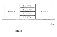
- Fig. 3 shows an example of the speckled broadcasting.
- one channel of HDTV is broadcasted in one time slot, and four channels of SDTV are broadcasted in another time slot.
- the SDTV and the HDTV are broadcasted changeably, so that a broadcasting using the definition depending on the program contents can be performed.
- the video encoding and video decoding of the HDTV are performed by a plurality of processors for SDTV which are combined.
- Fig. 4 shows the decoding processing of HDTV image in a video decoding part 225 for HDTV.
- the HDTV screen area is divided into four areas to be parallel-processed by four decoding processors 225A to 225D so as to perform the decoding processing of HDTV which has larger data size than that of SDTV.
- the video decoding part 225 consists of four decoding processors 225A to 225D for SDTV, so that it has an ability to decode four channels of SDTV at the same time. Thereby, as shown in Fig. 4, a parallel multichannel reception for decoding a plurality of SDTV at the same time by using the video decoding part 225 can be considered.
- the number of buffers equal to the number of channels of SDTV to be displayed is required. More specifically, as shown in Fig. 5, four reception buffers are required to perform the parallel multichannel reception for decoding four channels of SDTV at the same time. Thus, this case has a problem that the construction becomes complicated and the price raises.
- embodiments of this invention can provide a digital signal encoding apparatus, digital signal decoding apparatus, digital signal transmitting apparatus and its method which can perform the parallel multichannel reception of SDTV with a simple construction.
- Embodiments of the invention can provide a digital signal encoding apparatus, digital signal decoding apparatus, digital signal transmitting apparatus and its method, in which a transmission buffer and a reception buffer are each used as an single buffer when the first video signal is encoded and decoded.
- a transmission buffer and a reception buffer are each used as an single buffer when the first video signal is encoded and decoded.
- the transmission buffer and the reception buffer are divided into the number of the second video signals to use them as a plurality of divided transmission buffers and a plurality of divided reception buffers.
- symbol 100 denotes a digital satellite broadcasting system as a whole.
- An encoding control part 25 constantly checks the format of the supplied video signal, and outputs a format signal S25 to the encoding part 20 in accordance with the format.
- the encoding part 20 encodes the HDTV video signal S1H or the SDTV video signals S1A to S1D by the MPEG2 method in accordance with the format signal S25.
- Fig. 7 shows the encoding processing in the encoding transmitting apparatus 10.
- the processing starts at step SP1, and at step SP2, the format of the video signal is judged based on the format signal S25 (Fig. 6).
- An affirmative result at step SP2 signifies that the format of the video signal is HDTV, and the processing proceeds to step SP3.
- the encoding part 20 parallel-processes and encodes the HDTV video signal S1H by using four encoding processors 20A to 20D constituting the encoding part 20, and outputs the resultant to a transmission buffer 30 as encoded HDTV data S20H to temporarily store it.
- the encoding part 20 constantly checks the content by amount of the encoded HDTV data S20H in the transmission buffer 30 as content information S30, and controls the amount of codes to be generated of the encoded HDTV data S20H based on the content information S30.
- the encoding part 20 uses the whole capacity of the transmission buffer 30 to control the amount of codes to be generated of the encoded HDTV data S20H so that the transmission buffer 30 will not fail. That is, as shown in Fig. 8, the all capacity Vh of the transmission buffer 30 is used to encode the HDTV video signal S1H.
- a negative result at step SP2 signifies that the format of the video signal is SDTV, and the processing proceeds to step SP4.
- the encoding part 20 encodes the SDTV video signals S1A to S1D respectively by using the corresponding encoding processors 20A to 20D, and outputs them to the corresponding divided transmission buffers 30A to 30D as encoded SDTV data S20A to S20D.
- the encoding part 20 constantly checks the content by amount of each encoded SDTV data S20A to S20D in the divided transmission buffers 30A to 30D as content information S30 to control the amount of codes to be generated of the encoded SDTV data S20A to S20D based on the content information S30.
- the encoding part 20 controls the amount of codes to be generated of the encoded SDTV data S20A to S20D based on the divided buffer capacities Vs1 to Vs4 so that the divided transmission buffers 30A to 30D will not fail.
- the encoding transmitting apparatus 10 performs the encoding processing in accordance with the format of supplied video signal. More specifically, as shown in Fig. 9, when the HDTV video signal is supplied, the encoding processors 20A to 20D constituting the encoding part 20 parallel-processes and encodes the HDTV video signal, and the transmission buffer 30 is used as a single buffer. On the contrary to this, when the SDTV video signal is supplied, each of the encoding processors 20A to 20D, which constitute the encoding part 20, encodes the corresponding SDTV video signal, and the transmission buffer 30 is used as the divided transmission buffers 30A to 30D.
- the transmission buffer 30 successively reads out the encoded HDTV data S20H or the encoded SDTV data S20A to S20D at a fixed rate, and outputs the resultant to a multiplexing part 35.
- the multiplexing part 35 multiplexes the encoded HDTV data S20H or the encoded SDTV data S20A to S20D by the MPEG2 method, and outputs the resultant to a modulating part 40 as a transport stream S35.
- the multiplexing part 35 records the format of the video signal and the number N of multichannel in a table called program specific information (PSI) in the transport stream S35, and at the same time, records the buffer capacity Vh or Vs1 to Vs4 used for encoding in a table called sequence header in the transport stream S35.
- PSI program specific information
- the modulating part 40 performs a predetermined modulation processing on the transport stream S35 to transmit it as a transmission signal S10 via a transmission antenna 45.
- a satellite 50 receives and then amplifies the transmission signal S10 to transmit it as a transmission signal S50.
- the transmission signal S50 is supplied to a demodulating part 70 via a reception antenna 65.
- the demodulating part 70 demodulates the transmission signal S50 and outputs it to a separating part 75 as a transport stream S70.
- the separating part 75 performs the separating processing on the transport stream S70 by the MPEG2 method. That is, the separating part 75 generates the encoded HDTV data S75H or the encoded SDTV data S75A to S75D from the transport stream S70 to output the resultant to a reception buffer 80.
- a decoding control part 76 refers the PSI and the sequence header of the transport stream S70 to obtain the image format of the encoded data, the number of multichannel, and the buffer capacity Vh, or Vs1 to Vs4 used for encoding which are multiplexed on the transport stream S70, and outputs the format signal S76 corresponding to these to a decoding part 85.
- the decoding part 85 performs a processing in accordance with the format signal S76.
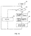
- Fig. 10 shows the decoding processing in the decoding receiving apparatus 60.
- the processing starts at step SP11, and at step SP12, the format of the video signal is judged based on the format signal S76 (Fig. 6). If an affirmative result at step SP12 signifies that the format of the video signal is HDTV, and the processing proceeds to step SP13.
- the decoding receiving apparatus 60 uses all of the buffer capacity Vh of the reception buffer 80 to perform buffering. More specifically, the reception buffer 80 once takes-in the encoded HDTV data S75H supplied from the separating part 75, thereafter, successively reads out it at a predetermined timing to output it to the decoding part 85.
- the decoding part 85 parallel-processes and decodes the encoded HDTV data S75H by using four decoding processors 85A to 85D constituting the decoding part 85, and outputs it to a television receiver (not shown) as an HDTV video signal S85H.
- a negative result at step SP12 signifies that the format of the video signal is SDTV, and in this case, the processing proceeds to step SP14.
- the decoding receiving part 60 confirms the number of channels of the SDTV video signal multiplied on the transport stream S70. More specifically, the decoding part 60 obtains the number N of multiplexed channels from the format signal S76 (Fig. 6). Then, at stop SP15, the reception buffer 80 is controlled as virtually and independently divided reception buffers 80A to 80D having the respective divided buffer capacities Vs1 to Vs4 shown in Fig. 8.
- the decoding receiving part 60 performs the decoding processing by using the divided reception buffers 80A to 80D. More specifically, the divided reception buffers 80A to 80D once take-in the encoded SDTV data S75A to S75D respectively, which are supplied from the separating part 75, and thereafter, successively read out them at a predetermined timing to output them to the decoding part 85 respectively.
- the decoding part 85 decodes the SDTV video signals S1A to S1D by using corresponding decoding processors 85A to 85D, and outputs them to a television receiver (not shown) as SDTV video signals S85A to S85D respectively.
- the decoding receiving apparatus 60 performs the decoding processing in accordance with the format of supplied video signal. That is, as shown in Fig. 11, when the HDTV video signal is supplied, the reception buffer 80 is used as a single buffer, and the decoding processors 85A to 85D constituting the decoding part 85 parallel-process and decode the HDTV video signal. On the contrary, when the SDTV video signal is supplied, the reception buffer 80 is used as the divided reception buffers 80A to 80D, and each of the decoding processors 85A to 85D, which constitute the decoding part 85, decodes the corresponding SDTV video signal.
- the encoding part 20 parallel-processes and encodes the HDTV video signal S1H by using four encoding processors 20A to 20D constituting the encoding part 20, and outputs it to the transmission buffer 30 as encoded HDTV data S20H.
- the transmission buffer 30 is used as a single buffer.
- the encoded HDTV data S20H is temporarily stored in the transmission buffer 30 and then read out at a predetermined fixed rate successively to be transmitted as a transmission signal S10 through the multiplexing part 35, the modulating part 40, and the transmission antenna 45.
- the transmission signal S10 is received and amplified by the satellite 50 and transmitted as a transmission signal S50.
- the transmission signal S50 is received by the reception antenna 65 and output as encoded HDTV data S75H through the demodulating part 70 and the separating part 75.
- the reception buffer 80 is used as a single buffer, the same as the transmission buffer 30.
- the encoded HDTV data S75H is temporarily stored in the reception buffer 80 and then read out at a predetermined timing successively. Then, the encoded HDTV data S75H is parallel-processed and decoded by the decoding processors 80A to 80D to be output as an HDTV video signal S85H.
- the encoding part 20 encodes the SDTV video signals S1A to S1D by using four encoding processors 20A to 20D respectively, and outputs them as encoded SDTV data S20A to S20D respectively.
- the transmission buffer 30 is divided into four to be used as divided transmission buffers 30A to 30D respectively.
- the encoded SDTV data S20A to S20D are output to the divided transmission buffer 30A to 30D respectively.
- the encoded SDTV data S20A to S20D are temporarily stored in the corresponding divided transmission buffers 30A to 30D and then successively read out at a predetermined fixed rate to be transmitted as a transmission signal S10 through the multiplexing part 35, the modulating part 40, and the transmission antenna 45.
- the transmission signal S10 is received and amplified by the satellite 50, and transmitted as a transmission signal S50.
- the transmission signal S50 is received by the reception antenna 65 and output as SDTV data S75A to S75D through the demodulating part 70 and the separating part 75.
- the reception buffer 80 is divided into four, the same as the transmission buffer 30, to be used as independently divided reception buffers 80A to 80D respectively.
- the encoded SDTV data S75A to S75D are output to corresponding divided reception buffers 80A to 80D, and then temporarily stored therein and read out at a predetermined timing successively.
- the encoded SDTV data S75A to S75D are decoded by the corresponding decoding processors 85A to 85D in the decoding part 85 and output as SDTV video signals S85A to S85D to a television receiver (not shown).
- each of the transmission buffer 30 and the reception buffer 80 is used as a single buffer.
- the transmission buffer 30 and the reception buffer 80 are respectively divided into the number of the SDTV video signals to use them as a plurality of divided transmission buffers and a plurality of divided reception buffers. Therefore, a parallel multichannel transmission of SDTV and a parallel multichannel reception of SDTV can be performed without increasing of the number of reception buffers and transmission buffers.
- the number of encoding processors constituting the encoding part 20 and the number of decoding processors constituting the decoding part 80 are set to be four.
- the present invention is not limited to this, but the other number of the encoding processors and the decoding processors can be provided.
- one HDTV and a plurality of SDTV are alternately broadcasted in the speckled broadcasting.
- the present invention is not limited to this, but various combination, such as one HDTV and a plurality of extended definition television (EDTV), and a plurality of EDTV and a plurality of SDTV, can be also used for the speckled broadcasting.
- EDTV extended definition television
- one HDTV video signal and a plurality of SDTV video signals are encoded by the same encoding part.
- the present invention is not limited to this, but one encoding part for HDTV and a plurality of encoding parts for SDTV are provided so as to encode the HDTV video signal and SDTV video signals respectively.
- This case also has an advantage that the construction becomes simple by using the transmission buffer in common.
- each of a transmission buffer and a reception buffer is used as a single buffer when the first video signal is encoded and decoded.
- the transmission buffer and the reception buffer are divided into the number of second video signal to use them as a plurality of divided transmission buffers and a plurality of divided reception buffers, so as to perform a parallel multichannel transmission and reception without increasing the number of reception buffer and transmission buffer.
Abstract
Description
- This invention relates to digital signal encoding and/or decoding.
- A digital satellite broadcasting system using stationary satellite has been started to be used. In Fig. 1,
numeral 600 denotes a digital satellite broadcasting system as a whole. A transmission signal S200 transmitted from atransmission antenna 200 is received and amplified by asatellite 300 to be output as a transmission signal S300. The transmission signal S300 is received by areception antennas 400. Thereby, a broadcasting system having a wide service area which has little reception interference due to obstacles on the ground can be realized. The digital satellite broadcasting system uses an image compressive encoding method called moving picture experts group (MPEG2) to multiplex a plurality of channels on one transport stream and transmit it. - In the digital
satellite broadcasting system 600 shown in Fig. 2, video signals S201A to S201D and audio signals S202A to S202D are supplied from the exterior to an encoding transmittingapparatus 210. In theencoding transmitting apparatus 210, fourencoding parts 220A to 220D which have the same construction are connected to amultiplexing part 250, and the video signals S201A to S201D and the audio signals S202A to S202D are input tocorresponding encoding parts 220A to 220D. - A video encoding
part 221 and anaudio encoding part 222 included in the encodingpart 220A respectively encode the video signal S201A and the audio signal S202A by using the MPEG2 method, and they are output to atransmission buffer 230 as video encoded data S221 and audio encoded data S222 respectively. Thetransmission buffer 230 temporarily stores the video encoded data S221 and the audio encoded data S222, and then reads out them at a predetermined timing to output them to amultiplexing part 240. The video encodingpart 221 constantly checks the content by the amount of the video encoded data S221 in thetransmission buffer 230 as content information S230, and controls the amount of codes to be generated of the video encoded data S221 based on the content information S230. - The
multiplexing part 240 multiplexes the video encoded data S221 and the audio encoded data S222 and outputs the resultant to amultiplexing part 250 as multiplexed data S220A. Themultiplexing part 250 multiplexes the multiplexed data S220A and the multiplexed data S220B to S220D respectively output from theencoding parts 220B to 220D, and outputs the resultant to a modulatingpart 260 as a transport stream S250. The modulatingpart 260 performs a predetermined modulation on the transport stream S250 and transmits the resultant via thetransmission antenna 200 as a transmission signal S200. - The
satellite 300 receives and amplifies the transmission signal S200, and transmits the resultant as a transmission signal S300. In adecoding receiving apparatus 410, the transmission signal S300 is received by thereception antenna 400 to be demodulated at ademodulating part 420, and is output to a separatingpart 430 as a transport stream S420. The separatingpart 430 selects one of the video encoded data and one of the audio encoded data among from the encoded data multiplexed on the transport stream S420 in accordance with selection signal S460 output from aremote controller 460, and outputs these data to areception buffer 440 as video encoded data S431 and audio encoded data S432. - The video encoded data S431 and the audio encoded data S432 are temporarily stored in the
reception buffer 440 and then they are read out at a predetermined timing to be decoded by avideo decoding part 451 and anaudio decoding part 452. Thereafter, they are output to a television receiver (not shown) as a video signal S451 and an audio signal S452. - Here, in the MPEG2 method, the amount of codes to be generated by an encoding processing changes depending on the pattern of each picture of image to be encoded. In short, when the pattern is complicated, the amount of codes to be generated increases, and when the pattern is simple, the amount of codes to be generated decreases. However, the transmission signals S200 and S300 are transmitted at a fixed rate, so that the
transmission buffer 230 and thereception buffer 440 are provided to absorb the fluctuation of the rate. - In the digital satellite broadcasting system, so-called speckled broadcasting for broadcasting alternately a plurality of standard definition television (STDV) channels and one high definition television (HDTV) channel in one transponder has been studied. Fig. 3 shows an example of the speckled broadcasting. In one transponder, one channel of HDTV is broadcasted in one time slot, and four channels of SDTV are broadcasted in another time slot. In this way, the SDTV and the HDTV are broadcasted changeably, so that a broadcasting using the definition depending on the program contents can be performed.
- The video encoding and video decoding of the HDTV are performed by a plurality of processors for SDTV which are combined. Fig. 4 shows the decoding processing of HDTV image in a video decoding part 225 for HDTV. The HDTV screen area is divided into four areas to be parallel-processed by four
decoding processors 225A to 225D so as to perform the decoding processing of HDTV which has larger data size than that of SDTV. - The video decoding part 225 consists of four
decoding processors 225A to 225D for SDTV, so that it has an ability to decode four channels of SDTV at the same time. Thereby, as shown in Fig. 4, a parallel multichannel reception for decoding a plurality of SDTV at the same time by using the video decoding part 225 can be considered. - However, to perform the parallel multichannel reception in a receiving apparatus, the number of buffers equal to the number of channels of SDTV to be displayed is required. More specifically, as shown in Fig. 5, four reception buffers are required to perform the parallel multichannel reception for decoding four channels of SDTV at the same time. Thus, this case has a problem that the construction becomes complicated and the price raises.
- Various respective aspects of the invention are defined in the appended claims.
- In view of the foregoing, embodiments of this invention can provide a digital signal encoding apparatus, digital signal decoding apparatus, digital signal transmitting apparatus and its method which can perform the parallel multichannel reception of SDTV with a simple construction.
- Embodiments of the invention can provide a digital signal encoding apparatus, digital signal decoding apparatus, digital signal transmitting apparatus and its method, in which a transmission buffer and a reception buffer are each used as an single buffer when the first video signal is encoded and decoded. When the number N of second video signals which have the picture elements less than that of the first video signal are encoded and decoded, the transmission buffer and the reception buffer are divided into the number of the second video signals to use them as a plurality of divided transmission buffers and a plurality of divided reception buffers.
- The invention will now be described by way of example with reference to the accompanying drawings, throughout which like parts are referred to by like references, and in which:
- Fig. 1 is a schematic diagram showing the digital satellite broadcasting system;
- Fig. 2 is a block diagram showing the digital satellite broadcasting system;
- Fig. 3 is a schematic diagram showing the speckled broadcasting;
- Fig. 4 is a schematic diagram showing the division processing of the decoding part;
- Fig. 5 is a schematic diagram showing the use conditions of reception buffer in the speckled broadcasting;
- Fig. 6 is a block diagram showing a digital satellite broadcasting system;
- Fig. 7 is a flowchart showing the encoding processing in the speckled broadcasting;
- Fig. 8 is a schematic diagram showing the use condition of buffer in the speckled broadcasting;
- Fig. 9 is a schematic diagram showing the encoding processing in the speckled broadcasting;
- Fig. 10 is a flowchart showing the decoding processing in the speckled broadcasting; and
- Fig. 11 is a schematic diagram showing the decoding processing in the speckled broadcasting;
-
- In Fig. 6,
symbol 100 denotes a digital satellite broadcasting system as a whole. One channel of HDTV video signal S1H or N channels (here, N=4) of SDTV video signals S1A to S1D are supplied alternately from the exterior to an encodingpart 20 of an encoding transmittingapparatus 10 in accordance with the broadcasting time slot. - An
encoding control part 25 constantly checks the format of the supplied video signal, and outputs a format signal S25 to the encodingpart 20 in accordance with the format. The encodingpart 20 encodes the HDTV video signal S1H or the SDTV video signals S1A to S1D by the MPEG2 method in accordance with the format signal S25. - More specifically, Fig. 7 shows the encoding processing in the
encoding transmitting apparatus 10. The processing starts at step SP1, and at step SP2, the format of the video signal is judged based on the format signal S25 (Fig. 6). An affirmative result at step SP2 signifies that the format of the video signal is HDTV, and the processing proceeds to step SP3. - At step SP3, the encoding
part 20 parallel-processes and encodes the HDTV video signal S1H by using fourencoding processors 20A to 20D constituting the encodingpart 20, and outputs the resultant to atransmission buffer 30 as encoded HDTV data S20H to temporarily store it. The encodingpart 20 constantly checks the content by amount of the encoded HDTV data S20H in thetransmission buffer 30 as content information S30, and controls the amount of codes to be generated of the encoded HDTV data S20H based on the content information S30. - At this time, the
encoding part 20 uses the whole capacity of thetransmission buffer 30 to control the amount of codes to be generated of the encoded HDTV data S20H so that thetransmission buffer 30 will not fail. That is, as shown in Fig. 8, the all capacity Vh of thetransmission buffer 30 is used to encode the HDTV video signal S1H. - While, a negative result at step SP2 signifies that the format of the video signal is SDTV, and the processing proceeds to step SP4.
- At step SP4, the encoding
part 20 confirms the number of channels of the SDTV video signal to be multiplied. More specifically, the encodingpart 20 confirms the number of the SDTV video signals supplied to the encodingpart 20 to set this number as the number N (here, N=4) of multiplexed channels. Then, at step SP5, the capacity Vh of thetransmission buffer 30 is divided into N. That is, Fig. 8 shows the case where the number N of the multiplied channels is four, and the capacity Vh of thetransmission buffer 30 is divided into four. They are respectively controlled as independently dividedtransmission buffers 30A to 30D each having the divided buffer capacities Vs1 to Vs4. The buffers are unnecessary to have the same size, and for example, the divided buffer capacity may be large for channels requiring the high picture quality, and may be small for channels not requiring the high picture quality. - Then, at step SP6, the
encoding part 20 encodes the SDTV video signals S1A to S1D respectively by using the correspondingencoding processors 20A to 20D, and outputs them to the corresponding dividedtransmission buffers 30A to 30D as encoded SDTV data S20A to S20D. At this time, theencoding part 20 constantly checks the content by amount of each encoded SDTV data S20A to S20D in the dividedtransmission buffers 30A to 30D as content information S30 to control the amount of codes to be generated of the encoded SDTV data S20A to S20D based on the content information S30. As shown in Fig. 8, theencoding part 20 controls the amount of codes to be generated of the encoded SDTV data S20A to S20D based on the divided buffer capacities Vs1 to Vs4 so that the dividedtransmission buffers 30A to 30D will not fail. - In this way, the
encoding transmitting apparatus 10 performs the encoding processing in accordance with the format of supplied video signal. More specifically, as shown in Fig. 9, when the HDTV video signal is supplied, theencoding processors 20A to 20D constituting theencoding part 20 parallel-processes and encodes the HDTV video signal, and thetransmission buffer 30 is used as a single buffer. On the contrary to this, when the SDTV video signal is supplied, each of theencoding processors 20A to 20D, which constitute theencoding part 20, encodes the corresponding SDTV video signal, and thetransmission buffer 30 is used as the dividedtransmission buffers 30A to 30D. - In Fig. 6, the
transmission buffer 30 successively reads out the encoded HDTV data S20H or the encoded SDTV data S20A to S20D at a fixed rate, and outputs the resultant to a multiplexingpart 35. The multiplexingpart 35 multiplexes the encoded HDTV data S20H or the encoded SDTV data S20A to S20D by the MPEG2 method, and outputs the resultant to a modulatingpart 40 as a transport stream S35. At this time, the multiplexingpart 35 records the format of the video signal and the number N of multichannel in a table called program specific information (PSI) in the transport stream S35, and at the same time, records the buffer capacity Vh or Vs1 to Vs4 used for encoding in a table called sequence header in the transport stream S35. The modulatingpart 40 performs a predetermined modulation processing on the transport stream S35 to transmit it as a transmission signal S10 via atransmission antenna 45. - A
satellite 50 receives and then amplifies the transmission signal S10 to transmit it as a transmission signal S50. In adecoding receiving apparatus 60, the transmission signal S50 is supplied to ademodulating part 70 via a reception antenna 65. Thedemodulating part 70 demodulates the transmission signal S50 and outputs it to a separatingpart 75 as a transport stream S70. - The separating
part 75 performs the separating processing on the transport stream S70 by the MPEG2 method. That is, the separatingpart 75 generates the encoded HDTV data S75H or the encoded SDTV data S75A to S75D from the transport stream S70 to output the resultant to areception buffer 80. - A
decoding control part 76 refers the PSI and the sequence header of the transport stream S70 to obtain the image format of the encoded data, the number of multichannel, and the buffer capacity Vh, or Vs1 to Vs4 used for encoding which are multiplexed on the transport stream S70, and outputs the format signal S76 corresponding to these to adecoding part 85. Thedecoding part 85 performs a processing in accordance with the format signal S76. - More specifically, Fig. 10 shows the decoding processing in the
decoding receiving apparatus 60. The processing starts at step SP11, and at step SP12, the format of the video signal is judged based on the format signal S76 (Fig. 6). If an affirmative result at step SP12 signifies that the format of the video signal is HDTV, and the processing proceeds to step SP13. - At step SP13, as shown in Fig. 8, the
decoding receiving apparatus 60 uses all of the buffer capacity Vh of thereception buffer 80 to perform buffering. More specifically, thereception buffer 80 once takes-in the encoded HDTV data S75H supplied from the separatingpart 75, thereafter, successively reads out it at a predetermined timing to output it to thedecoding part 85. - The
decoding part 85 parallel-processes and decodes the encoded HDTV data S75H by using fourdecoding processors 85A to 85D constituting thedecoding part 85, and outputs it to a television receiver (not shown) as an HDTV video signal S85H. - On the other hand, a negative result at step SP12 signifies that the format of the video signal is SDTV, and in this case, the processing proceeds to step SP14.
- At step SP14, the
decoding receiving part 60 confirms the number of channels of the SDTV video signal multiplied on the transport stream S70. More specifically, thedecoding part 60 obtains the number N of multiplexed channels from the format signal S76 (Fig. 6). Then, at stop SP15, thereception buffer 80 is controlled as virtually and independently dividedreception buffers 80A to 80D having the respective divided buffer capacities Vs1 to Vs4 shown in Fig. 8. - At step SP16, the
decoding receiving part 60 performs the decoding processing by using the dividedreception buffers 80A to 80D. More specifically, the dividedreception buffers 80A to 80D once take-in the encoded SDTV data S75A to S75D respectively, which are supplied from the separatingpart 75, and thereafter, successively read out them at a predetermined timing to output them to thedecoding part 85 respectively. - The
decoding part 85 decodes the SDTV video signals S1A to S1D by usingcorresponding decoding processors 85A to 85D, and outputs them to a television receiver (not shown) as SDTV video signals S85A to S85D respectively. - In this way, the
decoding receiving apparatus 60 performs the decoding processing in accordance with the format of supplied video signal. That is, as shown in Fig. 11, when the HDTV video signal is supplied, thereception buffer 80 is used as a single buffer, and thedecoding processors 85A to 85D constituting thedecoding part 85 parallel-process and decode the HDTV video signal. On the contrary, when the SDTV video signal is supplied, thereception buffer 80 is used as the dividedreception buffers 80A to 80D, and each of thedecoding processors 85A to 85D, which constitute thedecoding part 85, decodes the corresponding SDTV video signal. - In the above construction, when the HDTV video signal S1H is supplied to the
encoding transmitting apparatus 10, theencoding part 20 parallel-processes and encodes the HDTV video signal S1H by using fourencoding processors 20A to 20D constituting theencoding part 20, and outputs it to thetransmission buffer 30 as encoded HDTV data S20H. At this time, thetransmission buffer 30 is used as a single buffer. - The encoded HDTV data S20H is temporarily stored in the
transmission buffer 30 and then read out at a predetermined fixed rate successively to be transmitted as a transmission signal S10 through the multiplexingpart 35, the modulatingpart 40, and thetransmission antenna 45. The transmission signal S10 is received and amplified by thesatellite 50 and transmitted as a transmission signal S50. - In the
decoding receiving apparatus 60, the transmission signal S50 is received by the reception antenna 65 and output as encoded HDTV data S75H through thedemodulating part 70 and the separatingpart 75. At this time, thereception buffer 80 is used as a single buffer, the same as thetransmission buffer 30. The encoded HDTV data S75H is temporarily stored in thereception buffer 80 and then read out at a predetermined timing successively. Then, the encoded HDTV data S75H is parallel-processed and decoded by thedecoding processors 80A to 80D to be output as an HDTV video signal S85H. - On the contrary, when four SDTV video signals S1A to S1D are supplied to the
encoding transmitting apparatus 10, theencoding part 20 encodes the SDTV video signals S1A to S1D by using fourencoding processors 20A to 20D respectively, and outputs them as encoded SDTV data S20A to S20D respectively. At this time, thetransmission buffer 30 is divided into four to be used as dividedtransmission buffers 30A to 30D respectively. The encoded SDTV data S20A to S20D are output to the dividedtransmission buffer 30A to 30D respectively. - The encoded SDTV data S20A to S20D are temporarily stored in the corresponding divided
transmission buffers 30A to 30D and then successively read out at a predetermined fixed rate to be transmitted as a transmission signal S10 through the multiplexingpart 35, the modulatingpart 40, and thetransmission antenna 45. The transmission signal S10 is received and amplified by thesatellite 50, and transmitted as a transmission signal S50. - In the
decoding receiving apparatus 60, the transmission signal S50 is received by the reception antenna 65 and output as SDTV data S75A to S75D through thedemodulating part 70 and the separatingpart 75. At this time, thereception buffer 80 is divided into four, the same as thetransmission buffer 30, to be used as independently dividedreception buffers 80A to 80D respectively. The encoded SDTV data S75A to S75D are output to corresponding dividedreception buffers 80A to 80D, and then temporarily stored therein and read out at a predetermined timing successively. Then, the encoded SDTV data S75A to S75D are decoded by the correspondingdecoding processors 85A to 85D in thedecoding part 85 and output as SDTV video signals S85A to S85D to a television receiver (not shown). - According to the above structure, in the
encoding transmitting apparatus 10 and thedecoding receiving apparatus 60, when the HDTV video signal is encoded and decoded, each of thetransmission buffer 30 and thereception buffer 80 is used as a single buffer. On the other hand, when a plurality of SDTV video signals are encoded and decoded, thetransmission buffer 30 and thereception buffer 80 are respectively divided into the number of the SDTV video signals to use them as a plurality of divided transmission buffers and a plurality of divided reception buffers. Therefore, a parallel multichannel transmission of SDTV and a parallel multichannel reception of SDTV can be performed without increasing of the number of reception buffers and transmission buffers. - Note that, in the above described embodiment, the number of encoding processors constituting the
encoding part 20 and the number of decoding processors constituting thedecoding part 80 are set to be four. However, the present invention is not limited to this, but the other number of the encoding processors and the decoding processors can be provided. - Further, in the above described embodiment, one HDTV and a plurality of SDTV are alternately broadcasted in the speckled broadcasting. However, the present invention is not limited to this, but various combination, such as one HDTV and a plurality of extended definition television (EDTV), and a plurality of EDTV and a plurality of SDTV, can be also used for the speckled broadcasting.
- Furthermore, in the above described embodiment, one HDTV video signal and a plurality of SDTV video signals are encoded by the same encoding part. However, the present invention is not limited to this, but one encoding part for HDTV and a plurality of encoding parts for SDTV are provided so as to encode the HDTV video signal and SDTV video signals respectively. This case also has an advantage that the construction becomes simple by using the transmission buffer in common.
- As described above, according to this invention, each of a transmission buffer and a reception buffer is used as a single buffer when the first video signal is encoded and decoded. On the other hand, when the number N of second video signals which each has the picture elements less than that of the first video signal are encoded and decoded, the transmission buffer and the reception buffer are divided into the number of second video signal to use them as a plurality of divided transmission buffers and a plurality of divided reception buffers, so as to perform a parallel multichannel transmission and reception without increasing the number of reception buffer and transmission buffer.
- While there has been described in connection with the preferred embodiments of the invention, it will be obvious to those skilled in the art that various changes and modifications may be aimed, therefore, to cover in the appended claims all such changes and modifications as fall within the true scope of the invention.
Claims (10)
- A digital signal encoding apparatus for encoding a first video signal or the number N (N is a natural number) of second video signals of which the number of picture elements is less than that of the first video signal, which is supplied from the exterior, comprising:control means for judging whether a video signal supplied from the exterior is said first video signal or said number N of second video signals;encoding means for encoding said first video signal or said N second video signals to output the result as first encoded data or the number N of second encoded data; anda buffer for temporarily storing said first encoded data or said number N of second encoded data and outputting it, and whereinsaid control means divides said buffer into N areas when it is judged that said video signal supplied from the exterior is said number N of second video signals, and controls said encoding means so as to encode in parallel said number N of second video signals with said buffer divided into N areas.
- A digital signal decoding apparatus for decoding first encoded data which is obtained by encoding a first video signal or the number N of second encoded data which are obtained by encoding the number N (N is a natural number) of second video signals of which the number of picture elements is less than that of the first video signal, comprising:control means for judging whether said encoded data is said first encoded data or said number N of second encoded data;a buffer for temporarily storing said first encoded data or said number N of second encoded data and outputting it; anddecoding means for decoding said first encoded data or said number N of second encoded data output from said buffer, and whereinsaid control means divides said buffer into N areas when it is judged that said encoded data is said number N of second data, and controls said decoding means to decode in parallel said number N of second video signals with said buffer divided into N areas.
- A digital signal transmitting apparatus for encoding and multiplexing a first video signal or the number N (N is a natural number) of second video signals of which the number of picture elements is less than that of the first video signal, which is supplied from the exterior, to transmit it, comprising:control means for judging whether a video signal supplied from the exterior is said first video signal or said number N of second video signals;encoding means for encoding said first video signal or said number N of second video signals to output it as first encoded data or the number N of second encoded data;a buffer for temporarily storing said first encoded data or said number N of second encoded data and outputting it;multiplexing means for multiplexing said first encoded data or said number N of second encoded data output from said buffer and outputting it as multiplexed data; andtransmitting means for transmitting said multiplexed data, and whereinsaid control means divides said buffer into N areas when it is judged that the video signal supplied from the exterior is said number N of second video signals, and controls said encoding means to encode in parallel said number N of second video signals with said buffer divided into N areas.
- A digital signal encoding method of encoding a first video signal or the number N (N is a natural number) of second video signals of which the number of picture elements is less than that of the first video signal, which is supplied from the exterior, comprising:a control step of judging whether a video signal supplied from the exterior is said first video signal or said number N of second video signals; andan encoding step of encoding said first video signal or said number N of second video signals to output it as first encoded data or N second encoded data, and whereinsaid control step divides said buffer into N areas when it is judged that the video signal supplied from the exterior is said number N of second video signals, and controls said encoding step to encode in parallel said number N of second video signals with said buffer divided into N areas.
- A digital signal decoding method of decoding first encoded data which is obtained by encoding a first video signal or the number N of second encoded data which are obtained by encoding the number N (N is a natural number) of second video signals of which the number of picture elements is less than that of the first video signal, comprising:a control step of judging whether said encoded data is said first encoded data or said number N of second encoded data; anda decoding step of decoding said first encoded data or said number N of second encoded data after temporarily storing it in a buffer, and whereinsaid control step divides said buffer into N areas when it is judged that said encoded data is said number N of second data, and controls said decoding step to decode in parallel said number N of second video signals with said buffer divided into N areas.
- A digital signal transmitting method of multiplexing and transmitting a first video signal or the number N (N is a natural number) of second video signals of which the number of picture elements is less than that of the first video signal, comprising:a control step of judging whether a video signal supplied from the exterior is said first video signal or said number N of second video signals;an encoding step of encoding said first video signal or said number N of second video signals to output it as first encoded data or the number N of second encoded data after temporarily storing it in a buffer; anda multiplexing step of multiplexing said first encoded data or said number N of second encoded data, and whereinsaid control means divides said buffer into N areas when it is judged that the video signal supplied from the exterior is said number N of second video signals, and controls said encoding step to encode in parallel said number N of second video signals with said buffer divided into N areas.
- An encoding apparatus for encoding source television signals, comprising:encoding means for encoding said source television signals with a plurality of encoding processors;buffering means for buffering encoded streams obtained by encoding said source television signals with said encoding means;transmitting means for transmitting said encoded streams subjected to the buffering by said buffering means; andcontrol means, in the case where said source television signal is a high resolution television signal, for controlling said encoding means and said buffering means so as to prevent said buffering means from overflow or underflow and to encode said high resolution television signal; and in the case where said source television signals are low resolution television signals of a plurality of channels, for controlling said encoding means and said buffering means so that said buffering means is divided into the number equal to that of said plurality of channels and said low resolution television signals of said plurality of channels are encoded by corresponding processors of said encoding means respectively so as to prevent each divided area from overflow or underflow.
- An encoding apparatus for encoding source television signals, comprising:encoding means for encoding said source television signals with a plurality of encoding processors;buffering means for buffering encoded stream obtained by encoding said source television signals with said encoding means; andcontrol means for judging whether said source television signal is a high resolution television signals or low resolution television signals, and then controlling an encoding process of said encoding means and a buffering process of said buffering means according to the judgement result.
- A decoding apparatus for decoding source encoded streams, comprising:buffering means for buffering said source encoded streams;decoding means for decoding said encoded streams supplied from said buffering beans with a plurality of decoding processors; andcontrol means, in the case where said source encoded stream is data generated from a high resolution television signal, for controlling said buffering means and said decoding means so as to prevent said buffering means from overflow or underflow and to decode said source encoded stream; and in the case where said source encoded streams are data generated from low resolution television signals of a plurality of channels, for controlling said decoding means and said buffering means so that said buffering means is divided into the number equal to that of said plurality of channels and that said source encoded streams of said plurality of channels are decoded by corresponding processors of said decoding means respectively so as to prevent each divided area from overflow or underflow.
- A decoding apparatus for decoding source encoded streams, comprising:buffering means for buffering said source encoded streams;decoding means for decoding said encoded streams supplied from said buffering means with a plurality of processors; andcontrol means for judging whether said source encoded stream is an encoded stream generated by encoding a high resolution television signal or by encoding low resolution television signals, and controlling a buffering process of said buffering means and a decoding process of said decoding means according to the judgement result.
Applications Claiming Priority (2)
| Application Number | Priority Date | Filing Date | Title |
|---|---|---|---|
| JP4949598A JPH11252550A (en) | 1998-03-02 | 1998-03-02 | Digital signal coder, digital signal decoder, digital signal transmitter and its method |
| JP4949598 | 1998-03-02 |
Publications (2)
| Publication Number | Publication Date |
|---|---|
| EP0940988A2 true EP0940988A2 (en) | 1999-09-08 |
| EP0940988A3 EP0940988A3 (en) | 2003-04-09 |
Family
ID=12832739
Family Applications (1)
| Application Number | Title | Priority Date | Filing Date |
|---|---|---|---|
| EP19990301574 Withdrawn EP0940988A3 (en) | 1998-03-02 | 1999-03-02 | Digital television signal encoding and/or decoding |
Country Status (5)
| Country | Link |
|---|---|
| US (1) | US6349115B1 (en) |
| EP (1) | EP0940988A3 (en) |
| JP (1) | JPH11252550A (en) |
| KR (1) | KR19990077518A (en) |
| CN (1) | CN1232347A (en) |
Cited By (2)
| Publication number | Priority date | Publication date | Assignee | Title |
|---|---|---|---|---|
| WO2002025955A1 (en) * | 2000-09-20 | 2002-03-28 | General Instrument Corporation | Processor allocation for channels in a video multi-processor system |
| EP1515550A1 (en) * | 2002-06-20 | 2005-03-16 | Sony Corporation | Decoding apparatus and decoding method |
Families Citing this family (16)
| Publication number | Priority date | Publication date | Assignee | Title |
|---|---|---|---|---|
| US5619501A (en) * | 1994-04-22 | 1997-04-08 | Thomson Consumer Electronics, Inc. | Conditional access filter as for a packet video signal inverse transport system |
| US6757025B1 (en) | 1999-04-09 | 2004-06-29 | Sony Corporation | Method for switching input terminals based on incoming signal format |
| US6976267B1 (en) | 1999-04-09 | 2005-12-13 | Sony Corporation | Method and apparatus for controlling connections between devices |
| AU4208600A (en) * | 1999-04-09 | 2000-11-14 | Sony Electronics Inc. | Method for switching signal input based on device capability |
| US6731347B1 (en) * | 1999-04-09 | 2004-05-04 | Sony Corporation | Method for switching signal input based on device capability |
| US6826776B1 (en) | 1999-04-09 | 2004-11-30 | Sony Corporation | Method and apparatus for determining signal path |
| KR20020018730A (en) * | 2000-09-04 | 2002-03-09 | 박종섭 | Storing and playback of multi-channel video and audio signal |
| US20040013198A1 (en) * | 2001-08-31 | 2004-01-22 | Haruo Togashi | Encoding apparatus and method for encoding |
| US7386111B2 (en) * | 2004-02-10 | 2008-06-10 | Vonage Network Inc. | Method and apparatus for placing a long distance call based on a virtual phone number |
| US7558428B2 (en) * | 2004-09-13 | 2009-07-07 | Microsoft Corporation | Accelerated video encoding using a graphics processing unit |
| WO2006106683A1 (en) * | 2005-03-31 | 2006-10-12 | Pioneer Corporation | Information processing device, information processing method, information processing program, and recording medium containing the information processing program |
| JP2008141276A (en) * | 2006-11-30 | 2008-06-19 | Sanyo Electric Co Ltd | Tv signal processing circuit |
| US9143737B2 (en) | 2009-10-15 | 2015-09-22 | Verizon Patent And Licensing Inc. | Data distribution |
| US9258529B2 (en) * | 2009-10-15 | 2016-02-09 | Verizon Patent And Licensing Inc. | Data distribution |
| KR101966064B1 (en) | 2012-09-06 | 2019-04-05 | 삼성전자주식회사 | Bit-stream processing device for pipe-lined decoding and multimedia device including the same |
| US9848212B2 (en) * | 2015-07-10 | 2017-12-19 | Futurewei Technologies, Inc. | Multi-view video streaming with fast and smooth view switch |
Citations (3)
| Publication number | Priority date | Publication date | Assignee | Title |
|---|---|---|---|---|
| WO1991011074A1 (en) * | 1990-01-19 | 1991-07-25 | British Broadcasting Corporation | High definition television coder/decoder |
| US5212742A (en) * | 1991-05-24 | 1993-05-18 | Apple Computer, Inc. | Method and apparatus for encoding/decoding image data |
| EP0566092A2 (en) * | 1992-04-16 | 1993-10-20 | Sony Corporation | Multiple picture/sound signals decoding apparatus |
Family Cites Families (32)
| Publication number | Priority date | Publication date | Assignee | Title |
|---|---|---|---|---|
| GB9405914D0 (en) * | 1994-03-24 | 1994-05-11 | Discovision Ass | Video decompression |
| US5068650A (en) * | 1988-10-04 | 1991-11-26 | Bell Communications Research, Inc. | Memory system for high definition television display |
| US5691777A (en) * | 1988-10-17 | 1997-11-25 | Kassatly; Lord Samuel Anthony | Method and apparatus for simultaneous compression of video, audio and data signals |
| US5701582A (en) * | 1989-08-23 | 1997-12-23 | Delta Beta Pty. Ltd. | Method and apparatus for efficient transmissions of programs |
| US5640210A (en) * | 1990-01-19 | 1997-06-17 | British Broadcasting Corporation | High definition television coder/decoder which divides an HDTV signal into stripes for individual processing |
| DE4231158C5 (en) * | 1991-09-17 | 2006-09-28 | Hitachi, Ltd. | Method and device for the composition and display of images |
| JPH0675785A (en) * | 1992-06-29 | 1994-03-18 | Fujitsu Ltd | Pre-staging processing method, buffer management method and file system |
| JPH06303282A (en) * | 1993-04-13 | 1994-10-28 | Hitachi Ltd | Information processing system in information transmission system |
| US5646959A (en) * | 1993-09-09 | 1997-07-08 | Nec Corporation | Terminal adapter capable of reducing a memory capacity of a buffer memory |
| US5610841A (en) * | 1993-09-30 | 1997-03-11 | Matsushita Electric Industrial Co., Ltd. | Video server |
| US5581479A (en) * | 1993-10-15 | 1996-12-03 | Image Telecommunications Corp. | Information service control point, which uses different types of storage devices, which retrieves information as blocks of data, and which uses a trunk processor for transmitting information |
| US5583562A (en) * | 1993-12-03 | 1996-12-10 | Scientific-Atlanta, Inc. | System and method for transmitting a plurality of digital services including imaging services |
| US5544327A (en) * | 1994-03-01 | 1996-08-06 | International Business Machines Corporation | Load balancing in video-on-demand servers by allocating buffer to streams with successively larger buffer requirements until the buffer requirements of a stream can not be satisfied |
| US5880786A (en) * | 1994-06-15 | 1999-03-09 | Hitachi, Ltd. | Apparatus for picture decoding having frame memories commonly connected to one data bus and one address bus |
| US5764893A (en) * | 1994-08-03 | 1998-06-09 | Matsushita Electrical Co. Ltd. | Video-on-demand system uses adjusting positions of slots in a slot table to address additional image data distribution request from terminal devices |
| JP3864422B2 (en) * | 1994-09-16 | 2006-12-27 | ソニー株式会社 | Data transmission apparatus and data transmission method |
| EP0710033A3 (en) * | 1994-10-28 | 1999-06-09 | Matsushita Electric Industrial Co., Ltd. | MPEG video decoder having a high bandwidth memory |
| US5623311A (en) * | 1994-10-28 | 1997-04-22 | Matsushita Electric Corporation Of America | MPEG video decoder having a high bandwidth memory |
| KR0146127B1 (en) * | 1994-11-26 | 1998-09-15 | 구자홍 | Change velocity regeneration apparatus of vcr for digital hdtv |
| JP3489228B2 (en) * | 1994-12-13 | 2004-01-19 | ソニー株式会社 | Image storage device |
| US5828788A (en) * | 1995-06-29 | 1998-10-27 | Thomson Multimedia, S.A. | System for processing data in variable segments and with variable data resolution |
| US5787472A (en) * | 1995-07-31 | 1998-07-28 | Ibm Corporation | Disk caching system for selectively providing interval caching or segment caching of vided data |
| JP3801242B2 (en) * | 1995-10-31 | 2006-07-26 | 株式会社日立製作所 | Reduced image display device |
| JP3019787B2 (en) * | 1996-09-20 | 2000-03-13 | 日本電気株式会社 | Motion vector detection device |
| JPH10210465A (en) * | 1997-01-23 | 1998-08-07 | Hitachi Ltd | Code string edit device, image coding signal decoder and dynamic image coding signal decoder |
| US6084910A (en) * | 1997-01-31 | 2000-07-04 | Hughes Electronics Corporation | Statistical multiplexer for video signals |
| JPH10224794A (en) * | 1997-02-10 | 1998-08-21 | Kokusai Denshin Denwa Co Ltd <Kdd> | Hierarchy processing method for moving image coding data and its device |
| US6229850B1 (en) * | 1997-07-22 | 2001-05-08 | C-Cube Semiconductor Ii, Inc. | Multiple resolution video compression |
| US6151074A (en) * | 1997-09-30 | 2000-11-21 | Texas Instruments Incorporated | Integrated MPEG decoder and image resizer for SLM-based digital display system |
| US6226038B1 (en) * | 1998-04-03 | 2001-05-01 | Avid Technology, Inc. | HDTV editing and effects previsualization using SDTV devices |
| US6125147A (en) * | 1998-05-07 | 2000-09-26 | Motorola, Inc. | Method and apparatus for reducing breathing artifacts in compressed video |
| US6091776A (en) * | 1998-05-26 | 2000-07-18 | C-Cube Microsystems, Inc. | Delay balanced video encoder system |
-
1998
- 1998-03-02 JP JP4949598A patent/JPH11252550A/en active Pending
-
1999
- 1999-02-26 US US09/258,428 patent/US6349115B1/en not_active Expired - Fee Related
- 1999-03-02 KR KR1019990006760A patent/KR19990077518A/en not_active Application Discontinuation
- 1999-03-02 EP EP19990301574 patent/EP0940988A3/en not_active Withdrawn
- 1999-03-02 CN CN99102557A patent/CN1232347A/en active Pending
Patent Citations (3)
| Publication number | Priority date | Publication date | Assignee | Title |
|---|---|---|---|---|
| WO1991011074A1 (en) * | 1990-01-19 | 1991-07-25 | British Broadcasting Corporation | High definition television coder/decoder |
| US5212742A (en) * | 1991-05-24 | 1993-05-18 | Apple Computer, Inc. | Method and apparatus for encoding/decoding image data |
| EP0566092A2 (en) * | 1992-04-16 | 1993-10-20 | Sony Corporation | Multiple picture/sound signals decoding apparatus |
Non-Patent Citations (2)
| Title |
|---|
| BARBERO M ET AL: "DCT SOURCE CODING AND CURRENT IMPLEMENTATIONS FOR HDTV" EBU REVIEW- TECHNICAL, EUROPEAN BROADCASTING UNION. BRUSSELS, BE, no. 251, 1992, pages 22-33, XP000275388 ISSN: 0251-0936 * |
| KEESMAN G: "Multi-program video compression using joint bit-rate control" PHILIPS JOURNAL OF RESEARCH, ELSEVIER, AMSTERDAM, NL, vol. 50, no. 1, 1996, pages 21-45, XP004008201 ISSN: 0165-5817 * |
Cited By (5)
| Publication number | Priority date | Publication date | Assignee | Title |
|---|---|---|---|---|
| WO2002025955A1 (en) * | 2000-09-20 | 2002-03-28 | General Instrument Corporation | Processor allocation for channels in a video multi-processor system |
| US7039115B1 (en) | 2000-09-20 | 2006-05-02 | General Instrument Corporation | Processor allocation for channels in a video multi-processor system |
| EP1515550A1 (en) * | 2002-06-20 | 2005-03-16 | Sony Corporation | Decoding apparatus and decoding method |
| EP1515550A4 (en) * | 2002-06-20 | 2010-06-02 | Sony Corp | Decoding apparatus and decoding method |
| US8224148B2 (en) | 2002-06-20 | 2012-07-17 | Sony Corporation | Decoding apparatus and decoding method |
Also Published As
| Publication number | Publication date |
|---|---|
| JPH11252550A (en) | 1999-09-17 |
| CN1232347A (en) | 1999-10-20 |
| US6349115B1 (en) | 2002-02-19 |
| KR19990077518A (en) | 1999-10-25 |
| EP0940988A3 (en) | 2003-04-09 |
Similar Documents
| Publication | Publication Date | Title |
|---|---|---|
| EP0940988A2 (en) | Digital television signal encoding and/or decoding | |
| US9532101B2 (en) | Digital broadcast receiver unit | |
| EP1081885B1 (en) | Receiver and receiving method | |
| RU99115826A (en) | MEMORY ARCHITECTURE FOR MULTI-FORMAT VIDEO PROCESSOR | |
| AU2001282625B2 (en) | Stream decoder | |
| EP0944258A1 (en) | Digital broadcasting system | |
| EP0868087A2 (en) | Multiplexing apparatus and method, transmitting apparatus and method, and recording medium | |
| KR100628619B1 (en) | Apparatus and method of multiple decoding | |
| JP3037822B2 (en) | Digital multi-channel transmission system receiver | |
| KR20060122331A (en) | Apparatus and method for receiving images of multiple channel in receiving digital multimedia broadcasting | |
| US6628678B2 (en) | Demultiplexer | |
| US7920623B2 (en) | Method and apparatus for simultaneous display of multiple audio/video programs transmitted over a digital link | |
| JP3382017B2 (en) | Method and apparatus for transmitting and receiving program information | |
| JPH11112448A (en) | Information transmitter, method therefor, information receiver, method therefor and transmission medium | |
| KR20000034384A (en) | Digital broadcasting receiver for data transfer path | |
| JPH0358582A (en) | Packet transmission system, packet transmitter and packet receiver for television signal | |
| KR100269369B1 (en) | Digital receiving device and method thereof having multi-window | |
| KR200156496Y1 (en) | Television for displaying program information | |
| JPH099217A (en) | Broadcast reception method and broadcast receiver | |
| KR100238137B1 (en) | Program specification information and addition information processing method | |
| KR20000034383A (en) | Digital broadcasting receiver having a digital video disk reproducing function | |
| KR19990075945A (en) | Service Data Processing Method of Satellite Broadcasting System | |
| KR20060010347A (en) | Wireless video transmit apparatus | |
| KR19980078967A (en) | Playback digital satellite broadcasting receiver and its control method | |
| JPH10191271A (en) | Program selection system |
Legal Events
| Date | Code | Title | Description |
|---|---|---|---|
| PUAI | Public reference made under article 153(3) epc to a published international application that has entered the european phase |
Free format text: ORIGINAL CODE: 0009012 |
|
| AK | Designated contracting states |
Kind code of ref document: A2 Designated state(s): AT BE CH CY DE DK ES FI FR GB GR IE IT LI LU MC NL PT SE |
|
| AX | Request for extension of the european patent |
Free format text: AL;LT;LV;MK;RO;SI |
|
| PUAL | Search report despatched |
Free format text: ORIGINAL CODE: 0009013 |
|
| AK | Designated contracting states |
Kind code of ref document: A3 Designated state(s): AT BE CH CY DE DK ES FI FR GB GR IE IT LI LU MC NL PT SE Designated state(s): AT BE CH CY DE DK ES FI FR GB GR IE IT LI LU MC NL PT SE |
|
| AX | Request for extension of the european patent |
Extension state: AL LT LV MK RO SI |
|
| RIC1 | Information provided on ipc code assigned before grant |
Ipc: 7H 04N 7/50 B Ipc: 7H 04N 7/26 B Ipc: 7H 04N 7/58 B Ipc: 7H 04N 7/24 A |
|
| 17P | Request for examination filed |
Effective date: 20030925 |
|
| AKX | Designation fees paid |
Designated state(s): DE FR GB |
|
| STAA | Information on the status of an ep patent application or granted ep patent |
Free format text: STATUS: THE APPLICATION HAS BEEN WITHDRAWN |
|
| 18W | Application withdrawn |
Effective date: 20040317 |