EP0938968A1 - Method and device to make seals for bags - Google Patents
Method and device to make seals for bags Download PDFInfo
- Publication number
- EP0938968A1 EP0938968A1 EP99400443A EP99400443A EP0938968A1 EP 0938968 A1 EP0938968 A1 EP 0938968A1 EP 99400443 A EP99400443 A EP 99400443A EP 99400443 A EP99400443 A EP 99400443A EP 0938968 A1 EP0938968 A1 EP 0938968A1
- Authority
- EP
- European Patent Office
- Prior art keywords
- profiles
- sealing film
- film
- strips
- closure
- Prior art date
- Legal status (The legal status is an assumption and is not a legal conclusion. Google has not performed a legal analysis and makes no representation as to the accuracy of the status listed.)
- Withdrawn
Links
Images


Classifications
-
- B—PERFORMING OPERATIONS; TRANSPORTING
- B65—CONVEYING; PACKING; STORING; HANDLING THIN OR FILAMENTARY MATERIAL
- B65D—CONTAINERS FOR STORAGE OR TRANSPORT OF ARTICLES OR MATERIALS, e.g. BAGS, BARRELS, BOTTLES, BOXES, CANS, CARTONS, CRATES, DRUMS, JARS, TANKS, HOPPERS, FORWARDING CONTAINERS; ACCESSORIES, CLOSURES, OR FITTINGS THEREFOR; PACKAGING ELEMENTS; PACKAGES
- B65D33/00—Details of, or accessories for, sacks or bags
- B65D33/16—End- or aperture-closing arrangements or devices
- B65D33/25—Riveting; Dovetailing; Screwing; using press buttons or slide fasteners
- B65D33/2508—Riveting; Dovetailing; Screwing; using press buttons or slide fasteners using slide fasteners with interlocking members having a substantially uniform section throughout the length of the fastener; Sliders therefor
- B65D33/2541—Riveting; Dovetailing; Screwing; using press buttons or slide fasteners using slide fasteners with interlocking members having a substantially uniform section throughout the length of the fastener; Sliders therefor characterised by the slide fastener, e.g. adapted to interlock with a sheet between the interlocking members having sections of particular shape
-
- A—HUMAN NECESSITIES
- A44—HABERDASHERY; JEWELLERY
- A44B—BUTTONS, PINS, BUCKLES, SLIDE FASTENERS, OR THE LIKE
- A44B19/00—Slide fasteners
- A44B19/10—Slide fasteners with a one-piece interlocking member on each stringer tape
- A44B19/16—Interlocking member having uniform section throughout the length of the stringer
-
- B—PERFORMING OPERATIONS; TRANSPORTING
- B31—MAKING ARTICLES OF PAPER, CARDBOARD OR MATERIAL WORKED IN A MANNER ANALOGOUS TO PAPER; WORKING PAPER, CARDBOARD OR MATERIAL WORKED IN A MANNER ANALOGOUS TO PAPER
- B31B—MAKING CONTAINERS OF PAPER, CARDBOARD OR MATERIAL WORKED IN A MANNER ANALOGOUS TO PAPER
- B31B70/00—Making flexible containers, e.g. envelopes or bags
- B31B70/74—Auxiliary operations
- B31B70/81—Forming or attaching accessories, e.g. opening devices, closures or tear strings
- B31B70/813—Applying closures
- B31B70/8131—Making bags having interengaging closure elements
- B31B70/8132—Applying the closure elements in the machine direction
Definitions
- the present invention relates to the field of sachets comprising closure strips with male and female closure profiles complementary.
- the closure strip is U-shaped according to the cross section of the profiles taken in the direction of their length. There are two profiles. Each profile is located on a branch of the U. One of these branches is welded to a wall of a bag, so that by tightening the branches of the U one on the other, the profiles close on all two walls.
- US 3,164,186 describes a sachet provided with a funnel comprising a closure strip.
- a tubular film is welded to this closure strip, so as to line the inner wall of the funnel portion provided with this band.
- Re 34 554 also describes closure strips provided with one or two sealing films. These films are welded to the strips or coextruded with them and form a seal between the complementary profiles, when these are engaged one in the other.
- the object of the invention is to provide a method and a device for sealing additional male or female profiles already engaged in each other.
- the method and the device according to the invention weld an edge of the sealing film on at least one of the closing strips, after this film has been introduced between the profiles.
- the method and the device according to the invention are used to introduce a sealing film between two strips of closure each providing a sheet capable of forming a bag wall. More particularly, this sealing film can be introduced between the profiles of a double closing device.
- the method according to the invention is characterized by the fact that at least one closure strip is removed for completely clear the space to the right of the other strip (s) closing.
- the device for this particular embodiment of the process then comprises guide means for spreading at least one closure strip to completely clear the space in front of the or other closure strips.
- the maximum angle between the strips of closing apart from each other can then be approximately 90 °.
- the invention relates to a method and a device for introducing the sealing film in the form of a sheet simple between profiles.
- the invention relates to a method and a device for introducing between profiles a sealing film having its lateral parts folded longitudinally on itself, to form a double sheet.
- the invention also relates to a closure device with profiles or a bag fitted with such a device, characterized in that it comprises a sealing film introduced between the profiles according to the method of the present invention.
- the method according to the invention is used to form sachets 300 provided with a film sealing 100.
- a tube 200 provided with a closing device simple 3, feeds a device 1 for forming sachets, in accordance with the present invention.
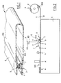
- Such a tube 200 is shown in Figure 1. It includes a folded film on itself, to form a lower sheet 204 and an upper sheet 206. Each of these sheets 204 and 206, capable of forming a wall of a bag 300, respectively has a lower closure strip 4 and upper 6. Each strip 4, 6 is welded or coextruded on the edge longitudinal free of each sheet 204, 206.
- the lower strip 4 comprises a female profile 7 in the form of a groove.
- the upper band 6 comprises a male section 9, capable of engaging in the female section 7.
- the shape of sections 7 and 9 can be of any shape known from the skilled person. There can also be several profiles 7, 9 on each strip 4, 6. Another form of tube 200 will be described later.
- FIG. 2 shows a device 1 for forming bags, fitted with a set 10 for inserting a sealing film 100 between profiles 7 and 9.
- the means for forming sachets and introducing the sealing film 100 are designated by letters from A to N.
- the tube 200 is unwound from the unwinding means A. It is then routed towards the assembly 10 for inserting the sealing film 100.
- This assembly 10 inserting the sealing film 100 comprises guide means B, C, D, E, H, I, J, K, means for positioning the sealing film G and welding means L.
- the sealing film 100 is unwound from of a coil 110 by unwinding means F.
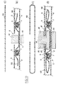
- FIG 3 shows in more detail the device 10 of introduction.
- This device 10 comprises several grooved rollers 12, 14, 16, 18 aligned. It also includes tumblers 20, 22, 24 to guide the upper strip 6, provided with the male profile 9, and intended for clear a space to the right of the strip 4 provided with the female profile 7.
- the male 9 and female 7 sections are not not shown.
- the tube 200 fitted with bands 4 and 6 passes between the first guide means B ( Figures 3a and 3b), then is routed to separation means C of the profiles ( Figures 3a and 3c).
- bands 4 and 6 are separated by a device separator 29 and guided by flat-edged casters 13 and 27.
- the separator device 29 comprises two grooves. These gorges have radially opposite openings and the respective bottoms of these grooves converge towards each other in the opposite direction to the movement of profiles 7, 9.
- a female profile is positioned 7 or male 9.
- the second guide means D are composed of a grooved caster 14 and a flat-edged caster 15, to.utes two analogues to the grooved caster and the flat edge caster first guide means B.
- the third guide means E are composed of a grooved caster 20 and a flat edge caster 21. As illustrated in Figure 3a, all of these two rollers 20 and 21 is inclined, both relative to the longitudinal plane and relative to the plane transverse of the assembly 10 ( Figure 3a, Figure 3e and Figure 4). The angle of inclination of these rollers relative to each of these planes is by 45 ° example.
- the sealing film 100 arrives vertically and transversely by relative to the direction of travel of the tube 200.
- the sealing film 100 is guided and positioned on the lower strip 4 by means of positioning G.
- the positioning means G consist of a roller positioning 30.
- This roller 30 is a cylinder of revolution whose axis of revolution is parallel to the plane of the closure strip 4 and perpendicular to the movement of this lower strip 4.
- the surface generator of external revolution of this cylinder grazes the profile 7 of the strip 4.
- the positioning means G can also be constituted a leaning and / or curved blade having a convex surface at contact of the sealing film 100. Other geometries are still possible for these positioning means G.
- the film 100 and the lower strip 4 are conveyed to fourth guide means H.
- These fourth guide means H consist of a grooved caster 16 and a flat edge caster 17. They are similar to the first guide means B and to the second guide means D. As shown in FIG. 3f, these means of guide H allow the sealing film 100 to be applied to the strip 4 of closing.
- the upper strip 6 and the upper sheet 206 are held at their free end in position vertical and arrive at the level of the fifth guide means I (FIG. 3a, figure 5.
- the planes of the lower 4 and upper 6 bands then make a angle ⁇ between them, which is at most equal to approximately 90 °. We thus spreads the upper strip 6 to completely clear the space necessary, in line with the latter, for positioning the film sealing 100 on the lower strip 4.
- the strip upper 6 and sheet 206 are gradually returned to position on the lower strip 4 and lower sheet 204 thanks to sixth means guide J, composed of a grooved caster 24 and a edge caster flat 25, and which are similar to the third guide means E.
- the male profile 9 is re-engaged in the female profile 7 at the level guide means K (FIG. 6, in this figure the guide means J are shown in dotted lines to signify that they are not in the same plane as the guide means K).
- These means K are composed of a grooved caster 18 and a flat-edged caster 19, both analogous to the first, third and fourth casters guide means B, D, H already described. From these guide means K, the sealing film 100 is inserted between the male 7 and female 9 sections lower 4 and upper 6 bands.
- All of the lower 4, upper 6, and sheet bands lower 204 and upper 206 again resting on each other, is routed to welding means L.
- These welding means L are composed, for example, of a pressure bar 40 and of means heaters 45, the pressure bar 40 applying the heating means 45 on the sealing film 100 and to weld the film 100 on the lower strip 4 ( Figure 7a).
- the film 100 is welded to the strip upper 6, thanks to a pressure bar 40, and heating means 45 for pressing and heating together the film 100 and the strip upper 6 ( Figure 7b).
- Other welding means L will be described more far.
- the tube 200 can then be routed to cutting means M to be transformed into bags 300, in a conventional manner.
- the bags 300 are then stacked at a stacking station N.
- the positioning means G can consist of rollers positioning 32, 34, 36, 38 ( Figures 8 and 9). These rollers 32, 34, 36, 38 have a shape similar to that of the rollers 30 already described. Such as shown in Figures 8 and 9, the rollers 36, 38 are oriented with their axis of revolution parallel to the movement of the lower strip 4. A slight space is provided between these rollers 36, 38 so as to guide the sealing film 100 arriving transversely to the displacement of the strip 4. Downstream of the rollers 36, 38, the sealing film 100 undergoes a 90 ° twist so as to extend across its width between the rollers 32, 34.
- rollers 32, 34 have their axes included in a plane parallel to that of strip 4 and perpendicular to the direction of movement of this strip 4.
- the space to be cleared to the right of the strip 4 for bring the sealing film 100 in contact with it is less than that shown in Figure 5.
- the guide means I can be inclined, for example by an angle of 45 °, above the lower strip 4. This makes it possible to reduce the torsion imposed on the upper strip 6, and to reduce the overall dimensions of the assembly 10.
- the positioning means G comprise at least one roller 30 ,.
- Figure 10a is shown a film seal 100 folded in a U around the roller 30.
- the plans of the parts of the film 100 downstream and upstream of the roll 30 are parallel to that of the lower strip 4.
- the direction of arrival of the film 100 on the roll 30 and that of departure make an angle ⁇ , which can be more or less open.
- This configuration can further reduce angle a, between bands lower 4 and- upper 6. It has been described above a mode of implementation work of the method according to the invention for introducing a sealing film 100 between two closing strips 4, 6 of a simple closing device 3 linked to sheets 204, 206 capable of forming the walls of a bag 300.
- the method for forming a closure strip with seal, described above can be used to equip 200 tubes with simple closing devices 3 as tubes 200 fitted with double closure 5.
- a double device 5 is shown in Figure 11. It includes a lower closure strip 4, and two upper strips of closure 6.
- the lower strip 4 is provided with two female sections 7.
- the two female sections 7 are spaced from one another over the width of the strip 4.
- the upper strips 6 are each provided with a male profile.
- the two upper bands 6 are separated from each other by a space 8 extending longitudinally with respect to the profiles 9.
- the lateral parts of bands 4 and 6, located on the other side of the profiles by relative to space 8, are respectively linked to lower sheets and upper 204 and 206 able to form the walls of a bag 300.
- This double closing device 5 is symmetrical with respect to space 8.
- the sheets 204 and 206 may form only one sheet folded back on itself, parallel to its longitudinal direction, to form a U-shaped profile cross section, or they can be welded to each other. In these two case, two symmetrical tubes are formed with respect to space 8.
- the process according to the invention can optionally also allow introduce a sealing film 100 between two strips 4, 6 and weld the sealing film 100 to closure strips, which will only be welded to a bag 300, or a sheet capable of forming such a bag 300, only later.
- FIG. 12 illustrates an example of bands 4, 6 which are not still attached to sheets 204, 206 capable of forming a bag 300.
- These bands 4, 6 constitute a double closure device 5 which differs from that shown in FIG. 11, by the fact that the lateral parts of the bands 4 and 6, located on the other side of the profiles with respect to the space 8, meet to form a U-shaped profile in a cross section.
- Each of the two sets of bands 4, 6 located on either side of the space 8, can be subsequently welded to walls of bags 300 of usual for the skilled person.
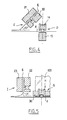
- Figure 13 schematically illustrates how to weld a film 100 or single seal on a double closing device.
- Figures 13b and 13d show cross sections made at level of the welding means L.
- Single and double sealing films 100 are shown in cross section, respectively in Figures 13a and 13c.
- the film 100 double of Figure 11c is formed by the folding in on itself, in the longitudinal direction of these lateral parts, while leaving space between the free longitudinal edges of the strip, in the middle zone of the latter.
- the film sealing 100 is welded by its longitudinal central zone only on the lower strip 4.
- the sealing film 100 is welded by its longitudinal central zone to the lower strip 4 and by two side parts on the upper strip 6.
- the welding operation is carried out by a welding bar 42, which presses, at the space 8, the sealing film 100 on the upper face of the lower strip 4 against an anvil 44.
- the bar 42 is movable in a back and forth movement perpendicular to the plane of movement in which the lower strip moves 4.
- the bar 42 has a flat face parallel to the plane of the lower strip 4. This flat face is perpendicular to the direction of pressure application necessary for welding and presses the film 100 and the lower strip 4 against anvil 44.
- the sealing bar 42 is provided with two shoulders 41, 43.
- the shoulders 41, 43 extend perpendicularly, on either side of the end of the bar 42, comprising the flat face parallel to the plane of the lower strip 4.
- These shoulders 41, 43 run along the bar 42 over the entire length thereof in the direction parallel to the movement of the lower strip 4.
- Other welding bars 46 flank the bar 42. They have a flat face perpendicular to the direction of application of the pressure welding via bar 42. These other welding bars 46 allow the longitudinal free edges of the strip to be welded the film 100, on the underside of the upper strip 6, by pressing them together on the shoulders 41, 43.
- a simple 100 sealing film has the following advantages: provides a seal over the entire length of the sections 7, 9; if he is in very fusible material (for example EVA), it encapsulates the ends welded profiles 7, 9 to make them also waterproof.
- EVA very fusible material
- a double film 100 also makes it possible to form an opening indicator. If it is long enough it can also, when pouring product contained in a bag 300, turn over to protect sections 7, 9 and possibly also form a pouring spout or a funnel.
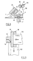
- FIG. 14 illustrates welding means L compatible with this embodiment of the invention.
- Device 1 for forming watertight closures according to the invention then comprises a pair of welding means similar to those described above and illustrated by figure 7.
- sealing bars 42 and 46 described above could be advantageously replaced by rollers, when continuous welding sealing film 100 on a closure device 3, 5 is desired.
Landscapes
- Engineering & Computer Science (AREA)
- Mechanical Engineering (AREA)
- Making Paper Articles (AREA)
Abstract
Description
La présente invention concerne le domaine des sachets comportant des bandes de fermeture avec des profilés de fermeture mâle et femelle complémentaires.The present invention relates to the field of sachets comprising closure strips with male and female closure profiles complementary.
L'introduction d'un film entre des profilés complémentaires pour rendre étanche une bande de fermeture est déjà connue.The introduction of a film between complementary profiles for sealing a closure strip is already known.
Ainsi, dans DK 90 167, la bande de fermeture est en forme de U selon la section transversale aux profilés pris dans le sens de leur longueur. Les profilés sont au nombre de deux. Chaque profilé est situé sur une branche du U. L'une de ces branches est soudée sur une paroi d'un sachet, de manière à ce qu'en resserrant les branches du U l'une sur l'autre, les profilés se referment sur l'ensemble des deux parois.Thus, in DK 90 167, the closure strip is U-shaped according to the cross section of the profiles taken in the direction of their length. There are two profiles. Each profile is located on a branch of the U. One of these branches is welded to a wall of a bag, so that by tightening the branches of the U one on the other, the profiles close on all two walls.
US 3 164 186 décrit un sachet muni d'un entonnoir comprenant une bande de fermeture. Un film tubulaire est soudé à cette bande de fermeture, de façon à venir tapisser la paroi interne de la portion d'entonnoir munie de cette bande. En engageant les profilés l'un dans l'autre, le film vient former un joint d'étanchéité entre les profilés complémentaires.US 3,164,186 describes a sachet provided with a funnel comprising a closure strip. A tubular film is welded to this closure strip, so as to line the inner wall of the funnel portion provided with this band. By engaging the profiles together, the film forms a seal between the complementary profiles.
Re 34 554 décrit aussi des bandes de fermeture munies d'un ou deux films d'étanchéité. Ces films sont soudés sur les bandes ou coextrudés avec elles et viennent former un joint d'étanchéité entre les profilés complémentaires, lorsque ceux-ci sont engagés l'un dans l'autre.Re 34 554 also describes closure strips provided with one or two sealing films. These films are welded to the strips or coextruded with them and form a seal between the complementary profiles, when these are engaged one in the other.
Mais ces documents n'enseignent pas comment rendre étanches des bandes de fermeture dont les profilés complémentaires mâles et femelles sont déjà engagés l'un dans l'autre.But these documents do not teach how to seal closure strips including complementary male and female profiles are already engaged in each other.
Le but de l'invention est de fournir un procédé et un dispositif pour rendre étanches des profilés complémentaires mâle ou femelle déjà engagés l'un dans l'autre.The object of the invention is to provide a method and a device for sealing additional male or female profiles already engaged in each other.
Plus précisément, l'invention est un procédé et un dispositif pour former une fermeture avec un joint, comprenant les étapes consistant à:
- entraíner un ensemble comprenant deux bandes de fermeture munies de profilés complémentaires engagés l'un dans l'autre, dans un déplacement parallèle au sens longitudinal des bandes ; et
- acheminer indépendamment des bandes de fermeture, un film d'étanchéité jusqu'à des moyens de positionnement.
- drive an assembly comprising two closure strips provided with complementary profiles engaged one inside the other, in a movement parallel to the longitudinal direction of the strips; and
- independently convey closure strips, a sealing film to positioning means.
Il est caractérisé en ce qu'il comprend en outre, les étapes consistant à:
- désengager les profilés l'un de l'autre ;
- écarter progressivement les deux bandes de fermeture ;
- introduire et positionner à l'aide des moyens de positionnement, le film entre les bandes de fermeture, de manière à ce que son déplacement en aval des moyens de positionnement soit parallèle à celui de l'une des bandes de fermeture ; et
- resserrer les bandes l'une sur l'autre jusqu'à ce que les profilés s'engagent l'un dans l'autre avec le film d'étanchéité entre eux.
- disengage the profiles from each other;
- gradually move the two closure strips apart;
- introduce and position using the positioning means, the film between the closure strips, so that its movement downstream of the positioning means is parallel to that of one of the closure strips; and
- tighten the strips one on top of the other until the profiles engage with each other with the sealing film between them.
L'invention concerne aussi un dispositif pour la mise en oeuvre de ce procédé. Ce dispositif comprend:
- un système d'entraínement de bandes de fermeture munies de profilés complémentaires engagés l'un dans l'autre, dans un déplacement parallèle au sens longitudinal de la bande ;
- des moyens de positionnementd'un film d'étanchéité entre les bandes de fermeture ;
- un dispositif de séparation des profilés, pour désengager les profilés l'un de l'autre ;
- des moyens de guidage pour écarter les bandes de fermeture l'une de l'autre, progressivement jusqu'aux moyens de positionnement ;
- des moyens pour resserrer les bandes l'une sur l'autre, jusqu'à ce que les profilés s'engagent l'un dans l'autre, avec le film entre eux.
- a system for driving closure strips provided with complementary profiles engaged one inside the other, in a movement parallel to the longitudinal direction of the strip;
- means for positioning a sealing film between the closure strips;
- a profile separation device for disengaging the profiles from one another;
- guide means for moving the closure strips apart from each other, progressively up to the positioning means;
- means for tightening the strips one on the other, until the profiles engage one in the other, with the film between them.
Avantageusement, le procédé et le dispositif selon l'invention permettent de souder un bord du film d'étanchéité sur au moins une des bandes de fermeture, après que ce film ait été introduit entre les profilés.Advantageously, the method and the device according to the invention weld an edge of the sealing film on at least one of the closing strips, after this film has been introduced between the profiles.
Avantageusement encore, le procédé et le dispositif selon l'invention sont utilisés pour introduire un film d'étanchéité entre deux bandes de fermeture munissant chacune un feuillet apte à former une paroi de sachet. Plus particulièrement, ce film d'étanchéité peut être introduit entre les profilés d'un dispositif de fermeture double.Advantageously also, the method and the device according to the invention are used to introduce a sealing film between two strips of closure each providing a sheet capable of forming a bag wall. More particularly, this sealing film can be introduced between the profiles of a double closing device.
Dans une variante avantageuse, le procédé selon l'invention est caractérisé par le fait que l'on écarte au moins une bande de fermeture pour dégager complètement l'espace au droit de la ou des autres bandes de fermeture. Le dispositif pour ce mode de mise en oeuvre particulier du procédé comprend alors des moyens de guidage pour écarter au moins une bande de fermeture afin de dégager complètement l'espace au droit de la ou des autres bandes de fermeture. L'angle maximum entre les bandes de fermeture écartées l'une de l'autre peut alors être approximativement de 90°.In an advantageous variant, the method according to the invention is characterized by the fact that at least one closure strip is removed for completely clear the space to the right of the other strip (s) closing. The device for this particular embodiment of the process then comprises guide means for spreading at least one closure strip to completely clear the space in front of the or other closure strips. The maximum angle between the strips of closing apart from each other can then be approximately 90 °.
Dans une variante avantageuse, l'invention concerne une méthode et un dispositif pour introduire le film d'étanchéité sous forme d'un feuillet simple entre des profilés.In an advantageous variant, the invention relates to a method and a device for introducing the sealing film in the form of a sheet simple between profiles.
Selon encore une autre variante, l'invention concerne une méthode et un dispositif pour introduire entre des profilés, un film d'étanchéité ayant ses parties latérales repliées longitudinalement sur lui-même, pour former un feuillet double.According to yet another variant, the invention relates to a method and a device for introducing between profiles a sealing film having its lateral parts folded longitudinally on itself, to form a double sheet.
L'invention concerne aussi un dispositif de fermeture avec profilés complémentaires ou un sachet muni d'un tel dispositif, caractérisé en ce qu'il comprend un film d'étanchéité introduit entre les profilés selon le procédé de la présente invention.The invention also relates to a closure device with profiles or a bag fitted with such a device, characterized in that it comprises a sealing film introduced between the profiles according to the method of the present invention.
D'autres aspects, avantages et buts de l'invention apparaítront à la lecture de la description détaillée qui suit.Other aspects, advantages and aims of the invention will become apparent from the reading of the detailed description which follows.
On comprendra mieux l'invention à l'aide des références aux dessins sur lesquels:
- la figure 1 représente schématiquement, en coupe et en vue perspective, un tube composé d'un film pour faire des sachets sur le dispositif et selon le procédé conformes à l'invention ;
- la figure 2 représente schématiquement, en coupe longitudinale, un dispositif de formation de sachets, conforme à la présente l'invention, équipé d'un ensemble, pour introduire un film d'étanchéité entre profilés complémentaires ;
- la figure 3 représente schématiquement, en vue de côté et de manière plus détaillée, un ensemble d'insertion d'un film d'étanchéité entre profilés complémentaires tel que celui équipant le dispositif de fabrication de sachets de la figure 2 ; la figure 3a représente en vue longitudinale, de côté par rapport au déplacement des profilés, des moyens B à K de guidage des profilés et de positionnement du film d'étanchéité de l'ensemble d'insertion du film d'étanchéité entre les profilés complémentaires ; les figures 3b, 3c, 3d, 3f et 3h représentent schématiquement, en coupe transversale, par rapport au déplacement des profilés, des moyens de guidage de l'ensemble d'insertion de la figure 3a ; les figures 3e et 3g représentent schématiquement en élévation latérale des moyens de guidage de l'ensemble d'insertion de la figure 3a ;
- la figure 4 représente schématiquement et en vue transversale par rapport au déplacement des profilés, les moyens de guidage D et E de profilés.
- la figure 5 représente schématiquement et en vue transversale par rapport au déplacement des profilés, les moyens de guidage H et J ainsi que les moyens de positionnement G du film d'étanchéité ;
- la figure 6 représente schématiquement et en vue transversale par rapport au déplacement des profilés, les moyens de guidage J et K ;
- la figure 7 représente schématiquement en coupe des moyens de soudage L ;
- la figure 8 représente schématiquement et en vue transversale par rapport au déplacement des profilés, une variante des moyens de guidage et de positionnement représentés à la figure 5 ;
- la figure 9 représente schématiquement et vus de dessus les moyens de positionnement G de la variante représentée à la figure 6 ;
- la figure 10 représente schématiquement une autre variante des moyens de positionnement G ; la figure 8a représente une vue de dessus de tels moyens ; la figure 8b représente une vue de côté en perspective de tels moyens ;
- la figure 11 représente schématiquement en coupe transversale par rapport à sa dimension longitudinale un tube muni d'un double dispositif de fermeture sur lequel peut être mis en oeuvre le procédé selon l'invention ;
- la figure 12 représente schématiquement en coupe transversale par rapport à sa dimension longitudinale un double dispositif de fermeture sur lequel peut être mis en oeuvre le procédé selon l'invention ;
- la figure 13 représente schématiquement en coupe transversale, par rapport au déplacement des profilés, des films d'étanchéité et les moyens correspondants de soudure des films d'étanchéité sur les bandes de fermeture ; la figure 11a représente un film d'étanchéité simple ; la figure 11b représente le soudage du film d'étanchéité simple représenté à la figure 11a ; la figure 11c représente un film d'étanchéité double ; la figure 11d représente le soudage du film d'étanchéité double de la figure 11c ; et
- la figure 14 représente schématiquement, en coupe, une variante des moyens de soudage L.
- Figure 1 shows schematically, in section and in perspective view, a tube composed of a film for making sachets on the device and according to the method according to the invention;
- FIG. 2 schematically represents, in longitudinal section, a device for forming bags, in accordance with the present invention, equipped with an assembly, for introducing a sealing film between complementary profiles;
- Figure 3 shows schematically, in side view and in more detail, an assembly for inserting a sealing film between complementary profiles such as that fitted to the device for manufacturing bags of Figure 2; FIG. 3a shows in longitudinal view, from the side with respect to the displacement of the profiles, means B to K for guiding the profiles and positioning the sealing film of the assembly for inserting the sealing film between the complementary profiles ; Figures 3b, 3c, 3d, 3f and 3h show schematically, in cross section, relative to the displacement of the profiles, guide means of the insertion assembly of Figure 3a; Figures 3e and 3g show schematically in side elevation of the guide means of the insertion assembly of Figure 3a;
- Figure 4 shows schematically and in transverse view with respect to the displacement of the profiles, the guide means D and E of profiles.
- Figure 5 shows schematically and in transverse view relative to the displacement of the profiles, the guide means H and J as well as the positioning means G of the sealing film;
- Figure 6 shows schematically and in transverse view relative to the displacement of the profiles, the guide means J and K;
- FIG. 7 schematically shows in section welding means L;
- Figure 8 shows schematically and in transverse view relative to the displacement of the profiles, a variant of the guide and positioning means shown in Figure 5;
- Figure 9 shows schematically and seen from above the positioning means G of the variant shown in Figure 6;
- FIG. 10 schematically represents another variant of the positioning means G; Figure 8a shows a top view of such means; Figure 8b shows a side perspective view of such means;
- Figure 11 shows schematically in cross section with respect to its longitudinal dimension a tube provided with a double closure device on which the method according to the invention can be implemented;
- Figure 12 shows schematically in cross section with respect to its longitudinal dimension a double closure device on which the method according to the invention can be implemented;
- Figure 13 shows schematically in cross section, with respect to the displacement of the profiles, sealing films and the corresponding means of welding the sealing films on the closure strips; Figure 11a shows a simple sealing film; Figure 11b shows the welding of the simple sealing film shown in Figure 11a; Figure 11c shows a double sealing film; Figure 11d shows the welding of the double sealing film of Figure 11c; and
- FIG. 14 schematically represents, in section, a variant of the welding means L.
Selon un mode de mise en oeuvre préférentiel, le procédé selon
l'invention est utilisé pour former des sachets 300 munis d'un film
d'étanchéité 100. A cette fin, un tube 200, muni d'un dispositif de fermeture
simple 3, alimente un dispositif 1 de formation de sachets, conforme à la
présente invention.According to a preferred embodiment, the method according to
the invention is used to form
Un tel tube 200 est représenté à la figure 1. Il comprend un film replié
sur lui-même, pour former un feuillet inférieur 204 et un feuillet supérieur
206. Chacun de ces feuillets 204 et 206, apte à former une paroi d'un
sachet 300, est muni respectivement d'une bande de fermeture inférieure 4
et supérieure 6. Chaque bande 4, 6 est soudée ou coextrudée sur le bord
libre longitudinal de chaque feuillet 204, 206. La bande inférieure 4
comprend un profilé femelle 7 en forme de gorge. La bande supérieure 6
comprend un profilé mâle 9, apte à s'engager dans le profilé femelle 7. La
forme des profilés 7 et 9 peuvent être de n'importe quelle forme connue par
l'homme du métier. Il peut aussi exister plusieurs profilés 7, 9 sur chaque
bande 4, 6. Une autre forme de tube 200 sera décrite plus loin.Such a
Sur la figure 2, est représenté un dispositif 1 de formation de
sachets, muni d'un ensemble 10 d'insertion d'un film d'étanchéité 100 entre
les profilés 7 et 9. Les moyens de formation de sachets et d'introduction du
film d'étanchéité 100 sont désignés par des lettres de A à N. Le tube 200
est déroulé à partir des moyens de dévidement A. Il est ensuite acheminé
vers l'ensemble 10 d'insertion du film d'étanchéité 100. Cet ensemble 10
d'insertion du film d'étanchéité 100 comprend des moyens de guidage B, C,
D, E, H, I, J, K, des moyens de positionnement du film d'étanchéité G et
des moyens de soudage L. Le film d'étanchéité 100 est déroulé à partir
d'une bobine 110 par des moyens de déroulement F.FIG. 2 shows a
La figure 3 représente de manière plus détaillée le dispositif 10
d'introduction. Ce dispositif 10 comprend plusieurs roulettes à gorges 12,
14, 16, 18 alignées. Il comprend aussi des roulettes à gorges 20, 22, 24
pour guider la bande supérieure 6, munie du profilé mâle 9, et destinées à
dégager un espace au droit de la bande 4 munie du profilé femelle 7. Afin
de ne pas surcharger la figure 3a, les profilés mâle 9 et femelle 7 ne sont
pas représentés. Des roulettes à chant plat 11, 13, 15, 17, 19, 21, 23, 25,
27, maintiennent la bande inférieure 4 et/ou la bande supérieure 6 en
position contre les roulettes à gorges 12, 14, 16, 18, 20, 22, 24 (la roulette à
champ plat 23 ne peut être représentée sur cette figure, elle se trouve
derrière la roulette à gorge 22).Figure 3 shows in more detail the
Le tube 200 muni des bandes 4 et 6 passe entre des premiers
moyens de guidage B (figures 3a et 3b), puis est acheminé vers des
moyens de séparation C des profilés (figures 3a et 3c). Au niveau des
moyens de séparation C, les bandes 4 et 6 sont séparées par un dispositif
séparateur 29 et guidées par des roulettes à chant plat 13 et 27. Le
dispositif séparateur 29 comprend deux gorges. Ces gorges ont des
ouvertures radialement opposées et les fonds respectifs de ces gorges
convergent l'un vers l'autre dans la direction opposée au déplacement des
profilés 7, 9. Dans chacune de ces gorges se positionnent un profilé femelle
7 ou mâle 9.The
Tandis que la bande 4 de fermeture et le feuillet inférieur 204 sont
guidés de manière rectiligne par des deuxièmes moyens de guidage D, la
bande de fermeture 6, le feuillet supérieur 206 sont acheminés vers des
troisièmes moyens de guidage E. Les deuxièmes moyens de guidage D
sont composés d'une roulette à gorges 14 et d'une roulette à chant plat 15,
to.utes deux analogues aux roulette à gorges et roulette à chant plat des
premiers moyens de guidage B. Les troisièmes moyens de guidage E sont
composés d'une roulette à gorges 20 et d'une roulette à chant plat 21.
Comme illustré par la figure 3a, l'ensemble de ces deux roulettes 20 et 21
est incliné, à la fois par rapport au plan longitudinal et par rapport au plan
transversal de l'ensemble 10 (figure 3a, figure 3e et figure 4). L'angle
d'inclinaison de ces roulettes par rapport à chacun de ces plans est par
exemple de 45°.While the
Le film d'étanchéité 100 arrive verticalement et transversalement par
rapport au sens de défilement du tube 200. Le film d'étanchéité 100 est
guidé et positionné sur la bande inférieure 4 par des moyens de
positionnement G. Dans ce mode de réalisation du dispositif selon
l'invention, les moyens de positionnement G sont constitués d'un rouleau de
positionnement 30. Ce rouleau 30 est un cylindre de révolution dont l'axe de
révolution est parallèle au plan de la bande de fermeture 4 et
perpendiculaire au déplacement de cette bande inférieure 4. La surface
génératrice de révolution externe de ce cylindre effleure le profilé 7 de la
bande 4. Les moyens de positionnement G peuvent être aussi constitués
d'une lame penchée et/ou incurvée présentant une surface convexe au
contact du film d'étanchéité 100. D'autres géométries sont encore
envisageables pour ces moyens de positionnement G.The sealing
Le film 100 et la bande inférieure 4 sont acheminés vers des
quatrièmes moyens de guidage H. Ces quatrièmes moyens de guidage H
sont composés d'une roulette à gorges 16 et d'une roulette à chant plat 17.
Ils sont analogues aux premiers moyens de guidage B et aux deuxièmes
moyens de guidage D. Comme représenté sur la figure 3f, ces moyens de
guidage H permettent d'appliquer le film d'étanchéité 100 sur la bande 4 de
fermeture. A ce niveau de l'avancement du tube 200, la bande supérieure 6
et le feuillet supérieur 206 sont maintenus à leur extrémité libre en position
verticale et arrivent au niveau des cinquièmes moyens de guidage I (figure
3a, figure 5. Les plans des bandes inférieure 4 et supérieure 6 font alors un
angle α entre eux, qui est au maximum égal à 90° approximativement. On
écarte ainsi la bande supérieure 6 pour dégager complètement l'espace
nécessaire, au droit de cette dernière, au positionnement du film
d'étanchéité 100 sur la bande inférieure 4.The
Après positionnement du film 100 sur la bande inférieure 4, la bande
supérieure 6 et le feuillet 206 sont progressivement remis en position sur la
bande inférieure 4 et le feuillet inférieur 204 grace à des sixièmes moyens
de guidage J, composés d'une roulette à gorges 24 et d'une roulette à chant
plat 25, et qui sont analogues aux troisièmes moyens de guidage E.After positioning the
Le profilé mâle 9 est réengagé dans le profilé femelle 7 au niveau
des moyens de guidage K (figure 6, sur cette figure les moyens de guidage
J sont représentés en pointillés pour signifier qu'ils ne se trouvent pas dans
le même plan que les moyens de guidage K). Ces moyens K sont
composés d'une roulette à gorges 18 et d'une roulette à chant plat 19,
toutes deux analogues aux roulettes des premiers, troisièmes et quatrièmes
moyens de guidage B, D, H déjà décrits. A partir de ces moyens de guidage
K, le film d'étanchéité 100 est inséré entre les profilés mâle 7 et femelle 9
des bandes inférieure 4 et supérieure 6.The
L'ensemble des bandes inférieure 4, supérieure 6, et des feuillets
inférieur 204 et supérieur 206 à nouveau reposant l'un sur l'autre, est
acheminé vers des moyens de soudage L. Ces moyens de soudage L sont
composés, par exemple, d'une barre de pression 40 et de moyens
chauffants 45, la barre de pression 40 appliquant les moyens chauffants 45
sur le film d'étanchéité 100 et pour souder le film 100 sur la bande inférieure
4 (figure 7a). Selon une variante, le film 100 est soudé sur la bande
supérieure 6, grâce à une barre de pression 40, et des moyens chauffants
45 permettant de presser et chauffer ensemble le film 100 et la bande
supérieure 6 (figure 7b). D'autres moyens de soudage L seront décrits plus
loin. Le tube 200 peut alors être acheminé vers des moyens de découpe M
pour être transformé en sachets 300, selon une manière conventionnelle.
Les sachets 300 sont ensuite empilés au niveau d'un poste d'empilement N.All of the lower 4, upper 6, and sheet bands
lower 204 and upper 206 again resting on each other, is
routed to welding means L. These welding means L are
composed, for example, of a
De nombreuses variantes du procédé et du dispositif décrit ci-dessus,
peuvent être envisagés tout en restant conformes à l'invention.
Ainsi, les moyens de positionnement G peuvent être constitués de rouleaux
de positionnement 32, 34, 36, 38 (figures 8 et 9). Ces rouleaux 32, 34, 36,
38 ont une forme analogue à celle des rouleaux 30 déjà décrits. Tels que
représentés sur les figures 8 et 9, les rouleaux 36, 38 sont orientés avec
leur axe de révolution parallèle au déplacement de la bande 4 inférieure. Un
léger espace est ménagé entre ces rouleaux 36, 38 de manière à guider le
film d'étanchéité 100 arrivant transversalement par rapport au déplacement
de la bande 4. En aval des rouleaux 36, 38, le film d'étanchéité 100 subit
une torsion de 90° de maniéré à s'étendre sur sa largeur entre les rouleaux
32, 34. Les rouleaux 32, 34 ont leur axe compris dans un plan parallèle à
celui de la bande 4 et perpendiculaire au sens de déplacement de cette
bande 4. Comme illustré par la figure 8, selon ce mode de réalisation du
dispositif selon l'invention, l'espace à dégager au droit de la bande 4 pour
amener le film d'étanchéité 100 au contact de celle-ci, est moindre que celui
représenté sur la figure 5. Ainsi, les moyens de guidage I peuvent être
inclinés, par exemple d'un angle de 45°, au-dessus de la bande inférieure 4.
Ceci permet de réduire la torsion imposée à la bande supérieure 6, et de
diminuer l'encombrement de l'ensemble 10.Many variants of the method and the device described above,
can be envisaged while remaining in accordance with the invention.
Thus, the positioning means G can consist of rollers
positioning 32, 34, 36, 38 (Figures 8 and 9). These
Comme représenté sur la figure 10, dans une autre variante du
dispositif selon l'invention, les moyens de positionnement G comprennent
au moins un rouleau 30,. Sur la figure 10a est représenté un film
d'étanchéité 100 replié en U autour du rouleau 30. Les plans des parties du
film 100 en aval et en amont du rouleau 30 sont parallèles à celui de la
bande inférieure 4. La direction d'arrivée du film 100 sur le rouleau 30 et
celle de départ font un angle β, qui peut être plus ou moins ouvert. Cette
configuration peut permettre de réduire encore l'angle a, entre des bandes
inférieure 4 et- supérieure 6. Il a été décrit ci-dessus un mode de mise en
oeuvre du procédé selon l'invention pour introduire un film d'étanchéité 100
entre deux bandes de fermeture 4, 6 d'un dispositif de fermeture simple 3
liées à des feuillets 204, 206 aptes à former les parois d'un sachet 300.As shown in Figure 10, in another variant of the
device according to the invention, the positioning means G comprise
at least one
Le procédé pour former une bande de fermeture avec joint, décrit ci-dessus
peut être utilisé pour équiper aussi bien des tubes 200 munis de
dispositifs de fermeture simples 3 que des tubes 200 munis de dispositifs de
fermeture double 5.The method for forming a closure strip with seal, described above
can be used to equip 200 tubes with
simple closing devices 3 as
Un dispositif double 5 est représenté sur la figure 11. Il comprend
une bande inférieure 4 de fermeture, et deux bandes supérieures de
fermeture 6. La bande inférieure 4 est munie de deux profilés femelles 7.
Les deux profilés femelles 7 sont espacés l'un de l'autre sur la largeur de la
bande 4. Les bandes supérieures 6 sont munies chacune d'un profilé mâle
9. Les deux bandes supérieures 6 sont séparées l'une de l'autre par un
espace 8 s'étendant longitudinalement par rapport aux profilés 9. Les
parties latérales des bandes 4 et 6, situées de l'autre côté des profilés par
rapport à l'espace 8, sont liées respectivement à des feuillets inférieurs et
supérieurs 204 et 206 aptes à former les parois d'un sachet 300. Ce
dispositif de fermeture double 5 est symétrique par rapport à l'espace 8. Les
feuillets 204 et 206 peuvent ne former qu'un feuillet replié sur lui même,
parallèlement à sa direction longitudinale, pour former un profil en U en
coupe transversale, ou ils peuvent être soudés l'un à l'autre. Dans ces deux
cas, on forme deux tubes symétriques par rapport à l'espace 8.A
Le procédé selon l'invention peut éventuellement aussi permettre
d'introduire un film d'étanchéité 100 entre deux bandes 4, 6 et de souder le
film d'étanchéité 100 à des bandes de fermeture, qui ne seront soudées à
un sachet 300, ou un feuillet apte à former un tel sachet 300,
qu'ultérieurement.The process according to the invention can optionally also allow
introduce a
La figure 12 illustre un exemple de bandes 4, 6 qui ne sont pas
encore fixées à des feuillets 204, 206 aptes à former un sachet 300. Ces
bandes 4, 6 constituent un dispositif de fermeture double 5 qui diffère de
celui représenté sur la figure 11, par le fait que les parties latérales des
bandes 4 et 6, situées de l'autre côté des profilés par rapport à l'espace 8,
se rejoignent pour former un profil en U selon une coupe transversale.
Chacun des deux ensembles de bandes 4, 6 situé de part et d'autre de
l'espace 8, peut être soudé ultérieurement sur des parois de sachets 300 de
manière usuelle pour l'homme du métier.Figure 12 illustrates an example of
La figure 13 illustre schématiquement comment souder un film
d'étanchéité 100 simple ou double sur un dispositif de fermeture double.
Les figures 13b et 13d représentent des coupes transversales réalisées au
niveau des moyens de soudage L.Figure 13 schematically illustrates how to weld a
Des films d'étanchéité 100 simple et double sont représentés en
coupe transversale, respectivement sur les figures 13a et 13c. Le film 100
double de la figure 11c est formé par le repliement sur lui-même, dans le
sens longitudinal, de ces parties latérales, tout en ménageant un espace
entre les bords libres longitudinaux de la bande, dans la zone médiane de
cette dernière.Single and
Une fois introduit entre les profilés 7, 9 des bandes 4, 6, le film
d'étanchéité 100 est soudé par sa zone médiane longitudinale uniquement
sur la bande inférieure 4. Lorsqu'il est double, le film d'étanchéité 100 est
soudé par sa zone médiane longitudinale sur la bande inférieure 4 et par
deux parties latérales sur la bande supérieure 6.Once introduced between the
L'opération de soudage est réalisée par une barre de soudage 42,
qui vient presser, au niveau de l'espace 8, le film d'étanchéité 100 sur la
face supérieure de la bande inférieure 4 contre une enclume 44. La barre
42 est mobile dans un mouvement de va et vient perpendiculaire au plan de
déplacement dans lequel se déplace la bande inférieure 4. La barre 42
comporte une face plane parallèle au plan de la bande inférieure 4. Cette
face plane est perpendiculaire à la direction d'application de la pression
nécessaire au soudage et vient plaquer le film 100 et la bande inférieure 4
contre l'enclume 44.The welding operation is carried out by a
Pour souder un film d'étanchéité 100 double, la barre de soudage 42
est munie de deux épaulements 41, 43. Les épaulements 41, 43 s'étendent
perpendiculairement, de part et d'autre de l'extrémité de la barre 42,
comportant la face plane parallèle au plan de la bande inférieure 4. Ces
épaulements 41, 43 longent la barre 42 sur toute la longueur de celle-ci
dans la direction parallèle au déplacement de la bande inférieure 4.
D'autres barres de soudage 46 viennent flanquer la barre 42. Elles ont une
face plane perpendiculaire à la direction d'application de la pression de
soudage par l'intermédiaire de la barre 42. Ces autres barres de soudage
46 permettent de souder les bords libres longitudinaux de la bande formant
le film 100, sur la face inférieure de la bande supérieure 6, en les pressant
ensemble sur les épaulements 41, 43.To weld a
Un film d'étanchéité 100 simple présente les avantages suivants : il
fournit un joint d'étanchéité sur toute la longueur des profilés 7, 9 ; s'il est en
matériau très fusible (par exemple EVA), il encapsule les extrémités
soudées des profilés 7, 9 pour les rendre elles aussi étanches. A simple 100 sealing film has the following advantages:
provides a seal over the entire length of the
Un film 100 double permet en plus de former un témoin d'ouverture.
S'il est suffisamment long il peut aussi, lorsque l'on déverse du produit
contenu dans un sachet 300, se retourner pour protéger les profilés 7, 9 et
éventuellement aussi former un bec verseur ou un entonnoir.A
Une autre manière de réaliser un témoin d'ouverture est de souder
chacun des bords libres longitudinaux d'un film d'étanchéité 100, sur une
bande 4, 6 différente. La figure 14 illustre des moyens de soudage L
compatibles avec ce mode de mise en oeuvre de l'invention. Le dispositif 1
de formation de fermetures étanches selon l'invention comprend alors une
paire de moyens de soudage analogues à ceux décrits ci-dessus et illustré
par la figure 7.Another way to make an opening indicator is to weld
each of the longitudinal free edges of a
Les barres de soudage 42 et 46 décrites ci-dessus pourraient être
avantageusement remplacées par des roulettes, lorsqu'un soudage continu
du film d'étanchéité 100 sur un dispositif de fermeture 3, 5 est souhaité.The sealing bars 42 and 46 described above could be
advantageously replaced by rollers, when continuous
Claims (20)
Applications Claiming Priority (2)
| Application Number | Priority Date | Filing Date | Title |
|---|---|---|---|
| FR9802272A FR2775215B1 (en) | 1998-02-25 | 1998-02-25 | METHOD AND DEVICE FOR FORMING SEALED CLOSURES FOR BAGS |
| FR9802272 | 1998-02-25 |
Publications (1)
| Publication Number | Publication Date |
|---|---|
| EP0938968A1 true EP0938968A1 (en) | 1999-09-01 |
Family
ID=9523348
Family Applications (1)
| Application Number | Title | Priority Date | Filing Date |
|---|---|---|---|
| EP99400443A Withdrawn EP0938968A1 (en) | 1998-02-25 | 1999-02-24 | Method and device to make seals for bags |
Country Status (3)
| Country | Link |
|---|---|
| US (1) | US6110090A (en) |
| EP (1) | EP0938968A1 (en) |
| FR (1) | FR2775215B1 (en) |
Families Citing this family (12)
| Publication number | Priority date | Publication date | Assignee | Title |
|---|---|---|---|---|
| US6216423B1 (en) * | 1997-11-07 | 2001-04-17 | Huntsman Kcl Corporation | Method and apparatus for placing a product in a flexible recloseable container |
| US5956924A (en) * | 1997-11-07 | 1999-09-28 | Rcl Corporation | Method and apparatus for placing a product in a flexible recloseable container |
| US20030044803A1 (en) * | 2000-09-22 | 2003-03-06 | Pedersen Finn Skou | Methods for diagnosis and treatment of diseases associated with altered expression of JAK1 |
| US6821238B2 (en) * | 2000-11-29 | 2004-11-23 | Illinois Tool Works Inc. | Method of preparing zipper for use in reclosable gusset bags |
| US6810641B2 (en) * | 2001-11-13 | 2004-11-02 | Illinois Tool Works, Inc. | Method and apparatus for forming double zipper bags |
| US20040220034A1 (en) * | 2003-04-30 | 2004-11-04 | Melchoir Greg W. | Method and apparatus for manufacturing a resealable package |
| US7290660B2 (en) | 2004-07-23 | 2007-11-06 | Tilman Paul A | Storage system having a disposable vacuum bag |
| US7437805B2 (en) * | 2006-06-23 | 2008-10-21 | Edward Alan Berich | Reclosable storage bag closure with internal valving |
| US7857514B2 (en) | 2006-12-12 | 2010-12-28 | Reynolds Foil Inc. | Resealable closures, polymeric packages and systems and methods relating thereto |
| US7857515B2 (en) * | 2007-06-15 | 2010-12-28 | S.C. Johnson Home Storage, Inc. | Airtight closure mechanism for a reclosable pouch |
| DE102009008129A1 (en) * | 2009-02-09 | 2010-10-07 | Focke & Co.(Gmbh & Co. Kg) | Method and device for producing bags |
| TWI769579B (en) * | 2020-07-15 | 2022-07-01 | 日商Ykk股份有限公司 | Reinforced film tape supply device |
Citations (8)
| Publication number | Priority date | Publication date | Assignee | Title |
|---|---|---|---|---|
| DK90167C (en) | 1958-05-09 | 1960-12-19 | Holger Emil Baggesgaard | Bag closure of flexible material for flat bags. |
| US3164186A (en) | 1962-07-13 | 1965-01-05 | Eberhard E H Weber | Plastic container |
| US3532571A (en) * | 1967-06-28 | 1970-10-06 | Steven Ausnit | Method and apparatus for forming continuous plastic tubing with separable pressure reclosable fastener strips attached to the surface thereof |
| US4807300A (en) * | 1985-08-27 | 1989-02-21 | Minigrip, Inc. | Plastic zipper bag with anchor-socket attachment arrangement |
| US4896775A (en) * | 1988-06-29 | 1990-01-30 | Zip-Pak Incorporated | Zippered thermal form tray system |
| US4969967A (en) * | 1989-01-18 | 1990-11-13 | Schurpack, Inc. | Method of manufacturing packing and strip material therefor |
| USRE34554E (en) | 1988-07-05 | 1994-03-01 | Minigrip, Inc. | Bags with reclosable plastic fastener having automatic sealing gasket means |
| WO1994025348A1 (en) * | 1993-05-05 | 1994-11-10 | Jan Jostler | A path for a packaging belt |
Family Cites Families (5)
| Publication number | Priority date | Publication date | Assignee | Title |
|---|---|---|---|---|
| US34554A (en) * | 1862-02-25 | Improvement in drawing apparatus for portable vessels | ||
| US3839128A (en) * | 1969-09-09 | 1974-10-01 | Modern Package Co Ltd | Apparatus for manufacturing thermoplastic containers having thermoplastic closures |
| US5584580A (en) * | 1994-02-24 | 1996-12-17 | Uniflex, Inc. | Tamper-resistant envelope closure |
| US5769772A (en) * | 1996-08-13 | 1998-06-23 | Tenneco Packaging Inc. | Packages made with both high-frequency/radio-frequency seals and conventional heat/pressure seals using combinations of polar and non-polar polymers |
| US5947603A (en) * | 1998-08-04 | 1999-09-07 | Reynolds Consumer Products, Inc. | Resealable closure mechanism having a slider device and separate housing |
-
1998
- 1998-02-25 FR FR9802272A patent/FR2775215B1/en not_active Expired - Fee Related
- 1998-12-08 US US09/207,247 patent/US6110090A/en not_active Expired - Fee Related
-
1999
- 1999-02-24 EP EP99400443A patent/EP0938968A1/en not_active Withdrawn
Patent Citations (8)
| Publication number | Priority date | Publication date | Assignee | Title |
|---|---|---|---|---|
| DK90167C (en) | 1958-05-09 | 1960-12-19 | Holger Emil Baggesgaard | Bag closure of flexible material for flat bags. |
| US3164186A (en) | 1962-07-13 | 1965-01-05 | Eberhard E H Weber | Plastic container |
| US3532571A (en) * | 1967-06-28 | 1970-10-06 | Steven Ausnit | Method and apparatus for forming continuous plastic tubing with separable pressure reclosable fastener strips attached to the surface thereof |
| US4807300A (en) * | 1985-08-27 | 1989-02-21 | Minigrip, Inc. | Plastic zipper bag with anchor-socket attachment arrangement |
| US4896775A (en) * | 1988-06-29 | 1990-01-30 | Zip-Pak Incorporated | Zippered thermal form tray system |
| USRE34554E (en) | 1988-07-05 | 1994-03-01 | Minigrip, Inc. | Bags with reclosable plastic fastener having automatic sealing gasket means |
| US4969967A (en) * | 1989-01-18 | 1990-11-13 | Schurpack, Inc. | Method of manufacturing packing and strip material therefor |
| WO1994025348A1 (en) * | 1993-05-05 | 1994-11-10 | Jan Jostler | A path for a packaging belt |
Also Published As
| Publication number | Publication date |
|---|---|
| FR2775215A1 (en) | 1999-08-27 |
| FR2775215B1 (en) | 2000-05-12 |
| US6110090A (en) | 2000-08-29 |
Similar Documents
| Publication | Publication Date | Title |
|---|---|---|
| EP0941928B1 (en) | Method and machine for making bags with a transverse zipper | |
| EP2035288B1 (en) | Plastic bag with gussets for food products and its method of manufacture | |
| EP1038774B1 (en) | Bag with transverse closure profiles and closure means for its manufacture | |
| EP0951989B1 (en) | Process for making bags with closure | |
| EP0792802B1 (en) | Automatic machine for forming, filling and closing of bags with transverse closure profiles | |
| EP0938968A1 (en) | Method and device to make seals for bags | |
| EP0918688B1 (en) | Method and machine for producing packaging bags using a flexible film | |
| FR2678237A1 (en) | METHOD OF CONTINUOUSLY INTRODUCING A FLUID INTO A SET OF CLOSED BAGS. | |
| EP0906866A1 (en) | Method and machine for the automatic manufacture of bags, as well as the bags thus obtained | |
| FR2583018A1 (en) | METHOD AND MACHINE FOR FORMING A RECLOSABLE BAG | |
| FR2910884A1 (en) | Gusset bag for receiving granulated food products, has gussets with arrangements acting as gripping handle and formed at level of folds to engage hand to facilitate draining of content and to engage another hand to raise base of bag | |
| CA2475059C (en) | Duplex bag | |
| EP2230074B1 (en) | Method for manufacturing a string of sachets provided with a slide | |
| FR2781718A1 (en) | PROCESS FOR MANUFACTURING FLAT BAGS AND MACHINE FOR IMPLEMENTING SAME | |
| EP2639176A1 (en) | Gusset bag | |
| EP1175351B1 (en) | Method and device for the production of a flexible pouch for a beverage | |
| EP2248436B1 (en) | Machine for automatically placing slides and associated method | |
| FR2787384A1 (en) | Procedure and machinery for the manufacturing of packaging having a pealable strip from a film type material | |
| WO2016156712A1 (en) | Method for continuously manufacturing a plastic bag for food products | |
| FR2813169A1 (en) | SLIDING CLOSURE SECTION, AND METHOD AND APPARATUS FOR MANUFACTURING SAME | |
| FR2943320A1 (en) | Packaging bag string for containing food product i.e. deep frozen food product, has packaging bags comprising actuation cursor for actuating opening and closing sections, where cursor is engaged on sections | |
| EP1228970B1 (en) | Open carton box with carton cover | |
| OA11132A (en) | Enclosure sealed process for manufacturing and packaging liquid in these enclosures | |
| FR2962717A1 (en) | Plastic sachets realizing device for vertical bag-filling machine, has female part whose edges have width ranging from top to bottom, and V-groove forming physical separation between sachet interior and plastic film zone forming gusset | |
| FR2499516A1 (en) | Flexible bottle formed of two plastics sheets - has cylindrical covers separated by lines of welding with filling hole which can be open or sealed |
Legal Events
| Date | Code | Title | Description |
|---|---|---|---|
| PUAI | Public reference made under article 153(3) epc to a published international application that has entered the european phase |
Free format text: ORIGINAL CODE: 0009012 |
|
| AK | Designated contracting states |
Kind code of ref document: A1 Designated state(s): DE FR GB |
|
| AX | Request for extension of the european patent |
Free format text: AL;LT;LV;MK;RO;SI |
|
| 17P | Request for examination filed |
Effective date: 20000214 |
|
| AKX | Designation fees paid |
Free format text: DE FR GB |
|
| 17Q | First examination report despatched |
Effective date: 20001103 |
|
| STAA | Information on the status of an ep patent application or granted ep patent |
Free format text: STATUS: THE APPLICATION IS DEEMED TO BE WITHDRAWN |
|
| 18D | Application deemed to be withdrawn |
Effective date: 20010515 |