EP0937792A1 - Method of producing a fibrous layer, for an absorbent article - Google Patents
Method of producing a fibrous layer, for an absorbent article Download PDFInfo
- Publication number
- EP0937792A1 EP0937792A1 EP98850187A EP98850187A EP0937792A1 EP 0937792 A1 EP0937792 A1 EP 0937792A1 EP 98850187 A EP98850187 A EP 98850187A EP 98850187 A EP98850187 A EP 98850187A EP 0937792 A1 EP0937792 A1 EP 0937792A1
- Authority
- EP
- European Patent Office
- Prior art keywords
- layer
- fibers
- bonding
- fibrous layer
- pattern
- Prior art date
- Legal status (The legal status is an assumption and is not a legal conclusion. Google has not performed a legal analysis and makes no representation as to the accuracy of the status listed.)
- Granted
Links
Images


Classifications
-
- A—HUMAN NECESSITIES
- A61—MEDICAL OR VETERINARY SCIENCE; HYGIENE
- A61F—FILTERS IMPLANTABLE INTO BLOOD VESSELS; PROSTHESES; DEVICES PROVIDING PATENCY TO, OR PREVENTING COLLAPSING OF, TUBULAR STRUCTURES OF THE BODY, e.g. STENTS; ORTHOPAEDIC, NURSING OR CONTRACEPTIVE DEVICES; FOMENTATION; TREATMENT OR PROTECTION OF EYES OR EARS; BANDAGES, DRESSINGS OR ABSORBENT PADS; FIRST-AID KITS
- A61F13/00—Bandages or dressings; Absorbent pads
- A61F13/15—Absorbent pads, e.g. sanitary towels, swabs or tampons for external or internal application to the body; Supporting or fastening means therefor; Tampon applicators
- A61F13/53—Absorbent pads, e.g. sanitary towels, swabs or tampons for external or internal application to the body; Supporting or fastening means therefor; Tampon applicators characterised by the absorbing medium
- A61F13/534—Absorbent pads, e.g. sanitary towels, swabs or tampons for external or internal application to the body; Supporting or fastening means therefor; Tampon applicators characterised by the absorbing medium having an inhomogeneous composition through the thickness of the pad
- A61F13/537—Absorbent pads, e.g. sanitary towels, swabs or tampons for external or internal application to the body; Supporting or fastening means therefor; Tampon applicators characterised by the absorbing medium having an inhomogeneous composition through the thickness of the pad characterised by a layer facilitating or inhibiting flow in one direction or plane, e.g. a wicking layer
- A61F13/53743—Absorbent pads, e.g. sanitary towels, swabs or tampons for external or internal application to the body; Supporting or fastening means therefor; Tampon applicators characterised by the absorbing medium having an inhomogeneous composition through the thickness of the pad characterised by a layer facilitating or inhibiting flow in one direction or plane, e.g. a wicking layer characterised by the position of the layer relative to the other layers
- A61F13/53747—Absorbent pads, e.g. sanitary towels, swabs or tampons for external or internal application to the body; Supporting or fastening means therefor; Tampon applicators characterised by the absorbing medium having an inhomogeneous composition through the thickness of the pad characterised by a layer facilitating or inhibiting flow in one direction or plane, e.g. a wicking layer characterised by the position of the layer relative to the other layers the layer is facing the topsheet
-
- A—HUMAN NECESSITIES
- A61—MEDICAL OR VETERINARY SCIENCE; HYGIENE
- A61F—FILTERS IMPLANTABLE INTO BLOOD VESSELS; PROSTHESES; DEVICES PROVIDING PATENCY TO, OR PREVENTING COLLAPSING OF, TUBULAR STRUCTURES OF THE BODY, e.g. STENTS; ORTHOPAEDIC, NURSING OR CONTRACEPTIVE DEVICES; FOMENTATION; TREATMENT OR PROTECTION OF EYES OR EARS; BANDAGES, DRESSINGS OR ABSORBENT PADS; FIRST-AID KITS
- A61F13/00—Bandages or dressings; Absorbent pads
- A61F13/15—Absorbent pads, e.g. sanitary towels, swabs or tampons for external or internal application to the body; Supporting or fastening means therefor; Tampon applicators
- A61F13/15577—Apparatus or processes for manufacturing
- A61F13/15617—Making absorbent pads from fibres or pulverulent material with or without treatment of the fibres
-
- A—HUMAN NECESSITIES
- A61—MEDICAL OR VETERINARY SCIENCE; HYGIENE
- A61F—FILTERS IMPLANTABLE INTO BLOOD VESSELS; PROSTHESES; DEVICES PROVIDING PATENCY TO, OR PREVENTING COLLAPSING OF, TUBULAR STRUCTURES OF THE BODY, e.g. STENTS; ORTHOPAEDIC, NURSING OR CONTRACEPTIVE DEVICES; FOMENTATION; TREATMENT OR PROTECTION OF EYES OR EARS; BANDAGES, DRESSINGS OR ABSORBENT PADS; FIRST-AID KITS
- A61F13/00—Bandages or dressings; Absorbent pads
- A61F13/15—Absorbent pads, e.g. sanitary towels, swabs or tampons for external or internal application to the body; Supporting or fastening means therefor; Tampon applicators
- A61F13/53—Absorbent pads, e.g. sanitary towels, swabs or tampons for external or internal application to the body; Supporting or fastening means therefor; Tampon applicators characterised by the absorbing medium
- A61F13/534—Absorbent pads, e.g. sanitary towels, swabs or tampons for external or internal application to the body; Supporting or fastening means therefor; Tampon applicators characterised by the absorbing medium having an inhomogeneous composition through the thickness of the pad
- A61F13/537—Absorbent pads, e.g. sanitary towels, swabs or tampons for external or internal application to the body; Supporting or fastening means therefor; Tampon applicators characterised by the absorbing medium having an inhomogeneous composition through the thickness of the pad characterised by a layer facilitating or inhibiting flow in one direction or plane, e.g. a wicking layer
- A61F13/53708—Absorbent pads, e.g. sanitary towels, swabs or tampons for external or internal application to the body; Supporting or fastening means therefor; Tampon applicators characterised by the absorbing medium having an inhomogeneous composition through the thickness of the pad characterised by a layer facilitating or inhibiting flow in one direction or plane, e.g. a wicking layer the layer having a promotional function on liquid propagation in at least one direction
- A61F13/53713—Absorbent pads, e.g. sanitary towels, swabs or tampons for external or internal application to the body; Supporting or fastening means therefor; Tampon applicators characterised by the absorbing medium having an inhomogeneous composition through the thickness of the pad characterised by a layer facilitating or inhibiting flow in one direction or plane, e.g. a wicking layer the layer having a promotional function on liquid propagation in at least one direction the layer having a promotional function on liquid propagation in the vertical direction
-
- A—HUMAN NECESSITIES
- A61—MEDICAL OR VETERINARY SCIENCE; HYGIENE
- A61F—FILTERS IMPLANTABLE INTO BLOOD VESSELS; PROSTHESES; DEVICES PROVIDING PATENCY TO, OR PREVENTING COLLAPSING OF, TUBULAR STRUCTURES OF THE BODY, e.g. STENTS; ORTHOPAEDIC, NURSING OR CONTRACEPTIVE DEVICES; FOMENTATION; TREATMENT OR PROTECTION OF EYES OR EARS; BANDAGES, DRESSINGS OR ABSORBENT PADS; FIRST-AID KITS
- A61F13/00—Bandages or dressings; Absorbent pads
- A61F13/15—Absorbent pads, e.g. sanitary towels, swabs or tampons for external or internal application to the body; Supporting or fastening means therefor; Tampon applicators
- A61F13/53—Absorbent pads, e.g. sanitary towels, swabs or tampons for external or internal application to the body; Supporting or fastening means therefor; Tampon applicators characterised by the absorbing medium
- A61F13/534—Absorbent pads, e.g. sanitary towels, swabs or tampons for external or internal application to the body; Supporting or fastening means therefor; Tampon applicators characterised by the absorbing medium having an inhomogeneous composition through the thickness of the pad
- A61F13/537—Absorbent pads, e.g. sanitary towels, swabs or tampons for external or internal application to the body; Supporting or fastening means therefor; Tampon applicators characterised by the absorbing medium having an inhomogeneous composition through the thickness of the pad characterised by a layer facilitating or inhibiting flow in one direction or plane, e.g. a wicking layer
- A61F13/53708—Absorbent pads, e.g. sanitary towels, swabs or tampons for external or internal application to the body; Supporting or fastening means therefor; Tampon applicators characterised by the absorbing medium having an inhomogeneous composition through the thickness of the pad characterised by a layer facilitating or inhibiting flow in one direction or plane, e.g. a wicking layer the layer having a promotional function on liquid propagation in at least one direction
- A61F13/53717—Absorbent pads, e.g. sanitary towels, swabs or tampons for external or internal application to the body; Supporting or fastening means therefor; Tampon applicators characterised by the absorbing medium having an inhomogeneous composition through the thickness of the pad characterised by a layer facilitating or inhibiting flow in one direction or plane, e.g. a wicking layer the layer having a promotional function on liquid propagation in at least one direction the layer having a promotional function on liquid propagation in the horizontal direction
-
- A—HUMAN NECESSITIES
- A61—MEDICAL OR VETERINARY SCIENCE; HYGIENE
- A61F—FILTERS IMPLANTABLE INTO BLOOD VESSELS; PROSTHESES; DEVICES PROVIDING PATENCY TO, OR PREVENTING COLLAPSING OF, TUBULAR STRUCTURES OF THE BODY, e.g. STENTS; ORTHOPAEDIC, NURSING OR CONTRACEPTIVE DEVICES; FOMENTATION; TREATMENT OR PROTECTION OF EYES OR EARS; BANDAGES, DRESSINGS OR ABSORBENT PADS; FIRST-AID KITS
- A61F13/00—Bandages or dressings; Absorbent pads
- A61F13/15—Absorbent pads, e.g. sanitary towels, swabs or tampons for external or internal application to the body; Supporting or fastening means therefor; Tampon applicators
- A61F13/15203—Properties of the article, e.g. stiffness or absorbency
- A61F2013/15284—Properties of the article, e.g. stiffness or absorbency characterized by quantifiable properties
- A61F2013/15406—Basis weight
-
- A—HUMAN NECESSITIES
- A61—MEDICAL OR VETERINARY SCIENCE; HYGIENE
- A61F—FILTERS IMPLANTABLE INTO BLOOD VESSELS; PROSTHESES; DEVICES PROVIDING PATENCY TO, OR PREVENTING COLLAPSING OF, TUBULAR STRUCTURES OF THE BODY, e.g. STENTS; ORTHOPAEDIC, NURSING OR CONTRACEPTIVE DEVICES; FOMENTATION; TREATMENT OR PROTECTION OF EYES OR EARS; BANDAGES, DRESSINGS OR ABSORBENT PADS; FIRST-AID KITS
- A61F13/00—Bandages or dressings; Absorbent pads
- A61F13/15—Absorbent pads, e.g. sanitary towels, swabs or tampons for external or internal application to the body; Supporting or fastening means therefor; Tampon applicators
- A61F13/15203—Properties of the article, e.g. stiffness or absorbency
- A61F2013/15284—Properties of the article, e.g. stiffness or absorbency characterized by quantifiable properties
- A61F2013/15447—Fibre dimension, e.g. denier or tex
-
- A—HUMAN NECESSITIES
- A61—MEDICAL OR VETERINARY SCIENCE; HYGIENE
- A61F—FILTERS IMPLANTABLE INTO BLOOD VESSELS; PROSTHESES; DEVICES PROVIDING PATENCY TO, OR PREVENTING COLLAPSING OF, TUBULAR STRUCTURES OF THE BODY, e.g. STENTS; ORTHOPAEDIC, NURSING OR CONTRACEPTIVE DEVICES; FOMENTATION; TREATMENT OR PROTECTION OF EYES OR EARS; BANDAGES, DRESSINGS OR ABSORBENT PADS; FIRST-AID KITS
- A61F13/00—Bandages or dressings; Absorbent pads
- A61F13/15—Absorbent pads, e.g. sanitary towels, swabs or tampons for external or internal application to the body; Supporting or fastening means therefor; Tampon applicators
- A61F13/53—Absorbent pads, e.g. sanitary towels, swabs or tampons for external or internal application to the body; Supporting or fastening means therefor; Tampon applicators characterised by the absorbing medium
- A61F2013/530131—Absorbent pads, e.g. sanitary towels, swabs or tampons for external or internal application to the body; Supporting or fastening means therefor; Tampon applicators characterised by the absorbing medium being made in fibre but being not pulp
- A61F2013/530138—Absorbent pads, e.g. sanitary towels, swabs or tampons for external or internal application to the body; Supporting or fastening means therefor; Tampon applicators characterised by the absorbing medium being made in fibre but being not pulp characterized by the fibre length
- A61F2013/530153—Absorbent pads, e.g. sanitary towels, swabs or tampons for external or internal application to the body; Supporting or fastening means therefor; Tampon applicators characterised by the absorbing medium being made in fibre but being not pulp characterized by the fibre length being long
-
- A—HUMAN NECESSITIES
- A61—MEDICAL OR VETERINARY SCIENCE; HYGIENE
- A61F—FILTERS IMPLANTABLE INTO BLOOD VESSELS; PROSTHESES; DEVICES PROVIDING PATENCY TO, OR PREVENTING COLLAPSING OF, TUBULAR STRUCTURES OF THE BODY, e.g. STENTS; ORTHOPAEDIC, NURSING OR CONTRACEPTIVE DEVICES; FOMENTATION; TREATMENT OR PROTECTION OF EYES OR EARS; BANDAGES, DRESSINGS OR ABSORBENT PADS; FIRST-AID KITS
- A61F13/00—Bandages or dressings; Absorbent pads
- A61F13/15—Absorbent pads, e.g. sanitary towels, swabs or tampons for external or internal application to the body; Supporting or fastening means therefor; Tampon applicators
- A61F13/53—Absorbent pads, e.g. sanitary towels, swabs or tampons for external or internal application to the body; Supporting or fastening means therefor; Tampon applicators characterised by the absorbing medium
- A61F2013/530131—Absorbent pads, e.g. sanitary towels, swabs or tampons for external or internal application to the body; Supporting or fastening means therefor; Tampon applicators characterised by the absorbing medium being made in fibre but being not pulp
- A61F2013/530182—Absorbent pads, e.g. sanitary towels, swabs or tampons for external or internal application to the body; Supporting or fastening means therefor; Tampon applicators characterised by the absorbing medium being made in fibre but being not pulp characterized by the connection between the fibres
-
- A—HUMAN NECESSITIES
- A61—MEDICAL OR VETERINARY SCIENCE; HYGIENE
- A61F—FILTERS IMPLANTABLE INTO BLOOD VESSELS; PROSTHESES; DEVICES PROVIDING PATENCY TO, OR PREVENTING COLLAPSING OF, TUBULAR STRUCTURES OF THE BODY, e.g. STENTS; ORTHOPAEDIC, NURSING OR CONTRACEPTIVE DEVICES; FOMENTATION; TREATMENT OR PROTECTION OF EYES OR EARS; BANDAGES, DRESSINGS OR ABSORBENT PADS; FIRST-AID KITS
- A61F13/00—Bandages or dressings; Absorbent pads
- A61F13/15—Absorbent pads, e.g. sanitary towels, swabs or tampons for external or internal application to the body; Supporting or fastening means therefor; Tampon applicators
- A61F13/53—Absorbent pads, e.g. sanitary towels, swabs or tampons for external or internal application to the body; Supporting or fastening means therefor; Tampon applicators characterised by the absorbing medium
- A61F13/534—Absorbent pads, e.g. sanitary towels, swabs or tampons for external or internal application to the body; Supporting or fastening means therefor; Tampon applicators characterised by the absorbing medium having an inhomogeneous composition through the thickness of the pad
- A61F13/537—Absorbent pads, e.g. sanitary towels, swabs or tampons for external or internal application to the body; Supporting or fastening means therefor; Tampon applicators characterised by the absorbing medium having an inhomogeneous composition through the thickness of the pad characterised by a layer facilitating or inhibiting flow in one direction or plane, e.g. a wicking layer
- A61F2013/53765—Absorbent pads, e.g. sanitary towels, swabs or tampons for external or internal application to the body; Supporting or fastening means therefor; Tampon applicators characterised by the absorbing medium having an inhomogeneous composition through the thickness of the pad characterised by a layer facilitating or inhibiting flow in one direction or plane, e.g. a wicking layer characterized by its geometry
- A61F2013/53778—Absorbent pads, e.g. sanitary towels, swabs or tampons for external or internal application to the body; Supporting or fastening means therefor; Tampon applicators characterised by the absorbing medium having an inhomogeneous composition through the thickness of the pad characterised by a layer facilitating or inhibiting flow in one direction or plane, e.g. a wicking layer characterized by its geometry with grooves
-
- A—HUMAN NECESSITIES
- A61—MEDICAL OR VETERINARY SCIENCE; HYGIENE
- A61F—FILTERS IMPLANTABLE INTO BLOOD VESSELS; PROSTHESES; DEVICES PROVIDING PATENCY TO, OR PREVENTING COLLAPSING OF, TUBULAR STRUCTURES OF THE BODY, e.g. STENTS; ORTHOPAEDIC, NURSING OR CONTRACEPTIVE DEVICES; FOMENTATION; TREATMENT OR PROTECTION OF EYES OR EARS; BANDAGES, DRESSINGS OR ABSORBENT PADS; FIRST-AID KITS
- A61F13/00—Bandages or dressings; Absorbent pads
- A61F13/15—Absorbent pads, e.g. sanitary towels, swabs or tampons for external or internal application to the body; Supporting or fastening means therefor; Tampon applicators
- A61F13/53—Absorbent pads, e.g. sanitary towels, swabs or tampons for external or internal application to the body; Supporting or fastening means therefor; Tampon applicators characterised by the absorbing medium
- A61F13/534—Absorbent pads, e.g. sanitary towels, swabs or tampons for external or internal application to the body; Supporting or fastening means therefor; Tampon applicators characterised by the absorbing medium having an inhomogeneous composition through the thickness of the pad
- A61F13/537—Absorbent pads, e.g. sanitary towels, swabs or tampons for external or internal application to the body; Supporting or fastening means therefor; Tampon applicators characterised by the absorbing medium having an inhomogeneous composition through the thickness of the pad characterised by a layer facilitating or inhibiting flow in one direction or plane, e.g. a wicking layer
- A61F2013/53791—Absorbent pads, e.g. sanitary towels, swabs or tampons for external or internal application to the body; Supporting or fastening means therefor; Tampon applicators characterised by the absorbing medium having an inhomogeneous composition through the thickness of the pad characterised by a layer facilitating or inhibiting flow in one direction or plane, e.g. a wicking layer being resilient or elastic
-
- Y—GENERAL TAGGING OF NEW TECHNOLOGICAL DEVELOPMENTS; GENERAL TAGGING OF CROSS-SECTIONAL TECHNOLOGIES SPANNING OVER SEVERAL SECTIONS OF THE IPC; TECHNICAL SUBJECTS COVERED BY FORMER USPC CROSS-REFERENCE ART COLLECTIONS [XRACs] AND DIGESTS
- Y10—TECHNICAL SUBJECTS COVERED BY FORMER USPC
- Y10T—TECHNICAL SUBJECTS COVERED BY FORMER US CLASSIFICATION
- Y10T156/00—Adhesive bonding and miscellaneous chemical manufacture
- Y10T156/10—Methods of surface bonding and/or assembly therefor
- Y10T156/1002—Methods of surface bonding and/or assembly therefor with permanent bending or reshaping or surface deformation of self sustaining lamina
- Y10T156/1007—Running or continuous length work
- Y10T156/1023—Surface deformation only [e.g., embossing]
-
- Y—GENERAL TAGGING OF NEW TECHNOLOGICAL DEVELOPMENTS; GENERAL TAGGING OF CROSS-SECTIONAL TECHNOLOGIES SPANNING OVER SEVERAL SECTIONS OF THE IPC; TECHNICAL SUBJECTS COVERED BY FORMER USPC CROSS-REFERENCE ART COLLECTIONS [XRACs] AND DIGESTS
- Y10—TECHNICAL SUBJECTS COVERED BY FORMER USPC
- Y10T—TECHNICAL SUBJECTS COVERED BY FORMER US CLASSIFICATION
- Y10T428/00—Stock material or miscellaneous articles
- Y10T428/24—Structurally defined web or sheet [e.g., overall dimension, etc.]
- Y10T428/24479—Structurally defined web or sheet [e.g., overall dimension, etc.] including variation in thickness
Definitions
- the present invention refers to a method of producing a fibrous material layer mainly intended to be incorporated in an absorbent article such as a diaper, pant diaper, incontinence guard, sanitary napkin or the like.
- Absorbent articles of the above mentioned kind are intended to absorb body liquids such as urine and blood. They usually comprises a liquid pervious topsheet, intended to be facing the wearer during use, in the form of a nonwoven material for example a spunbond material. It is also known to incorporate a liquid acquisition layer between the topsheet and the absorbent body, said liquid acquisition layer having the ability to quickly receive large amounts of liquid, to distribute it and temporarily store it before it is absorbed by the underlying absorbent body.
- a porous relatively thick acquisition layer for example in the form of a fibrous wadding, a carded fibrous web or other type of fibrous material has a high momentaneous liquid receiving capacity and can temporarily store liquid before it is absorbed by the absorbent body. The same applies for porous foam materials. The liquid is then drained successivley to the underlying absorbent body, after which the acquisition layer again has capacity to receive liquid from a repeated wetting.
- absorbent articles comprising such porous acquisition layer are for example disclosed in US-A-3,371,667, EP-A-0,312,118 and EP-A-0,474,777.
- topsheet materials used for absorbent articles of this kind usually a nonwoven material of synthetic fibers, e g a spunbond material, often has a lower acquisition rate for liquid than the acquisition layer, at which liquid can leak from the article before it reaches the acquisition layer.
- the problem can of course be solved by using a topsheet material which is very open and by that has a high liquid permeability.
- Such an open topsheet material can however cause problems with a too low strength and sharp fiber ends from the acquisition layer may penetrate the open topsheet material and irritate the user.
- the object of the present invention is to provide a method of producing a fibrous material layer having a high acqusition rate for liquid also at repeated wettings, has a high strength and wear resistance, high comfort and can be produced at a low cost.
- the method should besides be adapted to high production speeds.
- the material layer can be used as a liquid acquisition layer under a topsheet material, as a topsheet material or as an integrated topsheet/liquid acquisition layer.
- Figure 1 is a plan view of an absorbent article in the form of an incontinence guard.
- Figure 2 is a section according to the line II-II in Figure 1.
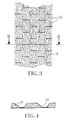
- Figure 3 shows schematically a piece of a fibrous material layer according to the invention.
- Figure 4 shows on an enlarged scale a section according to the line IV-IV in Figure 3.
- Figure 5 shows schematically in the form of a block diagram the different main steps of the method according to the invention.
- Figure 6 is a schematic side view of a process equipment for performing the method according to the invention.
- Figure 7 shows a schematic side view of a modified embodiment of the equalizing device included in the process equipment.
- Figure 8 shows schematically the feeding of the fibrous layer through en ejector.
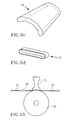
- Figure 9 a-d show some variants of the guiding means included in the equalizing device.
- Figure 10 shows a schematic side view of the feeding of the material layer towards the bonding station, in this case an ultrasonic welding device.
- Figure 11 shows schematically on an enlarged scale a special configuration of the pattern on the ultrasonic welding device for providing the bonding pattern.
- Figure 1 and 2 show schematically an example of an incontinence guard 1 comprising a liquid pervious topsheet 2, a liquid impervious backsheet 3 and a absorbent body 4 enclosed therebetween.
- a porous resilient liquid acquisition layer 5 is arranged between the liquid pervious topsheet 2 and the absorbent body 4.
- the liquid pervious topsheet 2 can comprise a nonwoven material, for example a spunbond material of synthetic filaments, a meltblown material, a thermobonded material or a bonded carded fibrous material.
- the liquid impervious backsheet 3 can consist of a plastic film, a nonwoven material which is coated with a liquid impervious material or a hydrophobic nonwoven material which resists liquid penetration.
- the topsheet 2 and the backsheet 3 have a larger surface area than the absorbent body 4 and the liquid acquisition layer 3 and extend outside the edges thereof.
- the layers 2 and 3 are interconnected within the projecting portions, for example by gluing or welding with heat or ultrasonic.
- the absorbent body 4 can be of any conventional kind.
- Examples of common absorption materials are cellulosic fluff pulp, tissue layers, highly absorbent polymers (so called superabsorbents), absorbent foam materials, absorbent nonwoven materials and the like. It is common to combine cellulosic fluff pulp with superabsorbents in an absorbent body. It is also common to have absorbent bodies comprising layers of different materials with different properties concerning liquid acquisition capacity, liquid distribution capacity and liquid storage capacity. This is wellknown for the person skilled in the art and need not be described in detail.
- the thin absorbent bodies which are common in for example baby diapers and incontinence guards often consist of a compressed mixed or layered structure of cellulosic fluff pulp and superabsorbent.
- an incontinence guard of the kind shown in Figure 1 is mainly intended to be used by persons suffering from a relatively light incontinence and is easily worn in ordinary underpants.
- the fastening means 6 serve to keep the incontinence guard in place in the underpants during use.
- glue patterns for example transverse, are of course possible as well as other types of fastening means such as hook and loop, snap fasteners, girdles, special underpants or the like.
- the incontinence guard is hous glass shaped with broader end portions 7 and a more narrow crotch portion 8 located between the end portions.
- the crotch portion 9 is the portion of the incontinence guard that is intended during use to be worn in the crotch between the legs of the wearer and serve as a receiving portion for the discharged body fluid.
- the incontinence guard shown in the drawings and described above only is a non-limiting example of an absorbent article.
- the absorbent article can also be a diaper, a pant diaper, a sanitary napkin or the like.
- the absorbent article can be disposable or reuseable. For reuseable articles other materials than the above described are however used as a liquid pervious topsheet and absorbent body respectively.
- a porous and resilient acquisition layer 5 having the ability to quickly receive large amounts of liquid and distribute the liquid and store it temporarily before it is absorbed by the underlying absorbent body 4. This ability should be essentially maintained also after wetting of the material.
- the acquisition layer 5 can either cover the entire absorbent body 4, extend outside thereof or cover only part of the central portions of the absorbent body.
- the acquisition layer 5 consists of a layer of continuous fibers 9, so called tow, vhich have been bonded together in points, spots or lines forming a bonding pattern 10, but otherwise are substantially unbonded to each other.
- the bonding pattern 10 is a pattern of lines with short lines arranged in a zigzag configuration.
- the bonding pattern is achieved by for example ultra sonic welding or other thermal bondning. Examples of other suitable thermal bonding methods are pattern calendering, laser bonding etc. This implies that at least some of the fibers in the tow are thermoplastic. Examples of thermo-plastic fibers are polyolefines, polyamides, polyester and the like. Also so called bicomponent fibers are included.
- thermobonding bonding can be made by a bonding agent through so called print bonding er dotbonding or mechanically through so called entangling by needling or by water jets.
- the choice of bonding type is mainly decided by which type of fibers are used in the tow.
- the design of the bonding pattern 10 can of course vary within wide limits.
- the pattern may be in the form of points, spots or preferably lines.
- the lines may be straight as well as curved and the length can vary from a few millimeters to extending transversely or diagonally across the entire article.
- Preferably the lines extend across or obliquely across the longitudinal direction of the fibers 9, so that a plurality of fibers are bonded to each other by each bonding line. It is also an advantage if different bonding lines overlap each other as seen across the longitudinal direction of the fibers, so that a main part of the fibers are bonded at least at some part of their length.
- the bonding pattern can be the same over the entire acquisition layer 5 or be different in different parts thereof, thus the bonding pattern can be more sparsely in the wetting area and tighter outside thereof. It is also possible to design the bonding pattern in such a way that the layer 5 will have different thickness in different parts of the article, for example thinner in the central portions thereof and thicker in the surrounding edge portions in order to create a bowl shape which provides a liquid receiving volume, alternatively thicker in the central portions than in the surrounding edge portions in order to provide a better body contact.
- FIGS 3 and 4 there are schematically shown a piece of a layer 11 of continuous fibers 9 which have been bonded in a simple bonding pattern 10 with transverse short lines.
- the fibers 9 are except at the bonding sites unbonded to each other.
- the layer 11 of continuous fibers 9 according to the invention can besides as a liquid acquisition layer in an absorbent article be arranged as a topsheet material closest to the wearer or as a combined topsheet/acquisition layer. It can also be bonded to a carrier material, for example a nonwoven.
- the method of producing the material layer according to the invention comprises several steps, which is schematically illustrated in Figures 5, 6 and 7.
- Fiber tow 12 is supplied in sacks or in the form of bales or rolls of continuous fibers, which either are straight, crimped or curled. Crimped or curled fibers are preferred in this case since they provide a very open and airy structure.
- the fibers in the tow can be of any suitable material such as polyethylene, polypropylene, polyamide, polyester, polylactide, polyvinyl acetate, cellulose acetate, regenerated cellulose such as viscose and rayon, or af bicomponent type with a shell of a polymer having a lower melting point and a core of a polymer having a higher melting point. Specially preferred are such fibers having a high resiliency, for example polyester, copolyester and polypropylene.
- the fiber thickness can vary but should be in the interval 0.5 to 10 dtex, preferably 1.5 to 25 and most preferably 2-15 dtex, if the material is to be used as an acquisition layer.
- the open airy structure in combination with the relatively coarse fiber dimension gives a very rapid liquid acquisition.
- the material is strong due to the continuous fibers which provide strength in the longitudinal direction, and the bonding pattern which provides strength in the transverse direction.
- bales or the like are opened in special opening equipments in which the fibers are separated from each other, stretched and spread out to an essentially evenly thick layer.
- the layer is bonded in the desired bonding pattern according to above and is cut in suitable lenghts either before or after application in en absorbent article.
- the bonding can alternatively be made after cutting.
- a tow is a relativley cheap delivery form of fibers as compared to nonwoven, waddings or the like which are normally used as acquisition materials.
- the opening device 13 comprises one or more pairs of rolls forming a roll nip, said rolls either being smooth or one roll is threaded and the opposite roll is a counter roll, the fiber tow being fed through said roll nip(s), which provides a separation of the fibers.
- the fibers are stretched during their passage through the roll nip(s) 14.
- This type of opening devicees are of conventional kind and are available on the market in different constructions.
- the opened fiber tow which now is in the form of a spread-out layer of separated individual fibers 9, is led through an ejector 18 which blows air into the material web 15 substantially in the longitudinal direction thereof.
- This through-air blowing is important for achieving the desired volume and bulkiness of the material web.
- Figure 8 there is schematically shown the feeding of the material web 15 through the ejector 18.
- the material is fed through the ejector 18 which in an enclosed chamber blows air across and along the material as seen in the feeding direction thereof.
- the fluffiness of the material web is markedly increased, especially if the fibers are crimped or helically curled.
- the flowing of air through the material web which either is made along, across or obliquely across the feeding direction of the material web, can be achieved in other ways than by an ejector, e g by means of a so called air knife .
- a flowing of air across the material web across the material web contributes to evening or equalizing thereof.
- the material web 15 is then fed to a bonding station 20, which in this embodiment is an ultra sonic welding device.
- This comprises an ultra sonic horn 21 arranged just opposite a pattern roll 22 ( Figure 10).
- the pattern roll 22 can besides a macropattern, e g a pattern of lines or other optional pattern, be provided with a micropattern, auneven or grooved surface, on the top surface of the protruded parts 24 of the pattern roll 22, which form the macropattern.
- a macropattern e g a pattern of lines or other optional pattern
- a micropattern auneven or grooved surface
- the total welding surface is divided in smaller parts, at which there will be less material to melt and the friction between the material web and the ultrasonic welding device is reduced.
- the height of the micropattern is of the magnitude tenth parts of a millimeter, this applies aöso for their length and width.
- the micropatten makes it possible to weld at higher speeds without risk that the joint breaks during bonding. It would also be possible to weld an uneven material web, i e in which the material thickness varies across the machine direction.
- thermal bonding methods such as pattern calendering, laser bonding etc.
- thermal bonding bonding can be made by means of a bonding agent, so called printbonding or dotbonding or mechanically by so called entangling by means of needles or water jets.
- the material web 15 can possibly after the pattern bonding be laminated to a nonwoven material 23 or a plastic film, which may be perforated or breathable, by thermobonding, e g ultrasonic welding or by a bondning agent, e g a glue.
- the nonwoven material 23 or the like can either be laminated to the material web 15 over the entire width thereof or in the form of strips be laminated only to the edges of the material web.
- the nonwoven material 23 or the like which is either hydrophobic or hydrophilic, serves to prevent spreading of liquid toward the edges of the absorbent article and to prevent rewetting of liquid towards the skin of the wearer.
- the pattern bonded material web 15, which optionally has been laminated to a nonwoven material or the like, can then either be wound on a winding roll or directly fed into a diaper machine or the like, where it is applied as a layer in an absorbent article such as a diaper, a pant diaper, an incontinence guard, a sanitary napkin or the like.
- one or more folding devices 17 are arranged before the ejector 18, the material web 15 being longitudinally folded one or more times in said folding device(s).
- the folding device 17 preferably consists of a guiding plate which forces a part of the material web 15 to be folded over a part or the rest of the material web.
- This folding can be made in different ways, such a double folding, in which half of the material web is folded over the other half, folding from two directions, in which a part of the material web's both edges are folded over the rest or a part of the rest of the material web, or overlap folding, in which the material web is folded from both direction in such a way that the folded portions of the material web overlap each other in the mid portision of the material web.
- This folding of the material web 15 is appropriate in such cases where the material web after the opening device has an uneven fiber distribution, which can be evened by folding the material web.
- an ejector 18 is arranged as described above.
- a further control of the fiber distribution in the transverse direction of the material web is obtained according to the embodiment shown in Figure 7 in a guiding device having a certain cross sectional shape, e g a funnel 19, through which the material web 15 is fed before it is fed towards the bonding station 20.
- the cross sectional shape of the funnel 19 thus decides the fiber distribution and by varying the shape of the funnel one can obtain a desired width of the material web and a desired districbution of the thickness of the material web 15 in its cross direction before it is bonded in the bonding station 20.
- FIG 9 a-c there are shown some variants of funnels 19 with different cross sectional shape.
- the funnel shown in Figure 9a is essentially straight-edged, tapers relatively quickly and leads into a long, narrow rectangular nib 19a. With this funnel the fibers will be evenly distributed over the entire width. The space within the funnel 19 should be only somewhat larger than the desired material volume. The nib 19a gives the fibers time to stabilize in an even layer.
- FIG 9b there is shown a funnel having a D-shaped cross section and with this it will be possible to have an increased concentration of fibers in the mid portion as compared to the edge portions. If the material web is refracted over the convex surface when the fibers are led into and out of the funnel there will be a shorter way for the fibers to pass at the centre of the funnel, and by this there will be an increased concentration of fibers at the centre of the material web.
- the fiber distribution can be controlled by the ovality and "brytningsgrad" at the entrance and exit of the funnel.
- the material web can at the exit of the funnel either be led straght forwards or be refracted upwards or downwards, which in turn can effect the fiber distribution.
- Figure 9c there is shown a funnel that is curved in the cross direction and where the material web is led over the concave surface and the fibers by that is guided out toward the edges, at which there is obtained an increased fiber concentration along the edges of the material web.
- the fiber distribution can be guided by the convexity and degree of refraction at the entrance and the exit.
- FIG 9d there is shown a guiding device in the form of an oval ring 19, i e it has an essentially shorter length than the funnels shown in Figures 9 a-c.
- the folding device 17 is not always necessary, only if the material web is uneven and need to be evened.
- An uneven material web may also be sufficiently even by passing it through two or more funnels or rings 19.
- the material web is fed towards the bonding station 20, which in the embodiment shown consists of en ultrasonic welding device.
- This comprises an ultrasonic horn 21 arranged just opposite a pattern roll 22 ( Figure 10).
- the feeding of the material web towards the ultrasonic welding device as well as the web tension of the material web 15 is of importance for the bonding of the material web in a controlled way.
- the problems which may occurt if the feeding of the material web to the ultrasonic welding device is not correctly made is that there will be a risk that:
- the funnel 19 or other type of guiding device for forming the material web in the cross direction is however not always necessary, and in these cases the material web is after through-air blowing in the ejector 18 fed directly into the bonding station 20 as is shown in Figure 6.
Landscapes
- Health & Medical Sciences (AREA)
- Engineering & Computer Science (AREA)
- Life Sciences & Earth Sciences (AREA)
- Biomedical Technology (AREA)
- Heart & Thoracic Surgery (AREA)
- Vascular Medicine (AREA)
- Epidemiology (AREA)
- Animal Behavior & Ethology (AREA)
- General Health & Medical Sciences (AREA)
- Public Health (AREA)
- Veterinary Medicine (AREA)
- Manufacturing & Machinery (AREA)
- Nonwoven Fabrics (AREA)
- Absorbent Articles And Supports Therefor (AREA)
- Orthopedics, Nursing, And Contraception (AREA)
Abstract
Description
- The present invention refers to a method of producing a fibrous material layer mainly intended to be incorporated in an absorbent article such as a diaper, pant diaper, incontinence guard, sanitary napkin or the like.
- Absorbent articles of the above mentioned kind are intended to absorb body liquids such as urine and blood. They usually comprises a liquid pervious topsheet, intended to be facing the wearer during use, in the form of a nonwoven material for example a spunbond material. It is also known to incorporate a liquid acquisition layer between the topsheet and the absorbent body, said liquid acquisition layer having the ability to quickly receive large amounts of liquid, to distribute it and temporarily store it before it is absorbed by the underlying absorbent body. This is important especially in today's thin compressed absorbent bodies often with a high amount of so called superabsorbents, which have a high absorption capacity but in many cases a too low absorption speed in order to momentaneously be able to absorb the large amount of liquid that can be discharged during a few seconds at urination.
- A porous relatively thick acquisition layer, for example in the form of a fibrous wadding, a carded fibrous web or other type of fibrous material has a high momentaneous liquid receiving capacity and can temporarily store liquid before it is absorbed by the absorbent body. The same applies for porous foam materials. The liquid is then drained successivley to the underlying absorbent body, after which the acquisition layer again has capacity to receive liquid from a repeated wetting.
- Examples of absorbent articles comprising such porous acquisition layer are for example disclosed in US-A-3,371,667, EP-A-0,312,118 and EP-A-0,474,777.
- The materials used today as acquisition layers in absorbent articles are mostly functioning well but are relatively expensive and can sometimes have an insufficient acquisition time, especially at the second and third wettings if large amounts of liquid are involved.
- It is previously known through EP-A-0,391,814 and GB-B-2,209,672 to use continuous nonbonded synthetic fibers, so called tow, in absorbent articles to spread liquid in the longitudinal direction of the article.
- Another problem is that conventional liquid pervious topsheet materials used for absorbent articles of this kind, usually a nonwoven material of synthetic fibers, e g a spunbond material, often has a lower acquisition rate for liquid than the acquisition layer, at which liquid can leak from the article before it reaches the acquisition layer. The problem can of course be solved by using a topsheet material which is very open and by that has a high liquid permeability. Such an open topsheet material can however cause problems with a too low strength and sharp fiber ends from the acquisition layer may penetrate the open topsheet material and irritate the user.
- The object of the present invention is to provide a method of producing a fibrous material layer having a high acqusition rate for liquid also at repeated wettings, has a high strength and wear resistance, high comfort and can be produced at a low cost. The method should besides be adapted to high production speeds. This has according to the invention been provided by taking at least one bundle of continous filaments, so called tow, which is opened and the filaments are separated and evened to a layer having the desired fiber distribution, after which the layer is bonded in points, spots or lines in a bonding pattern, but where the filaments otherwise are substantially unbonded to each other.
- Further features of the invention are evident form the following claims and from the description.
- The material layer can be used as a liquid acquisition layer under a topsheet material, as a topsheet material or as an integrated topsheet/liquid acquisition layer.
- The invention will below be closer described with reference to some of the embodiments shown in the accompanying drawings.
- Figure 1 is a plan view of an absorbent article in the form of an incontinence guard.
- Figure 2 is a section according to the line II-II in Figure 1.
- Figure 3 shows schematically a piece of a fibrous material layer according to the invention.
- Figure 4 shows on an enlarged scale a section according to the line IV-IV in Figure 3.
- Figure 5 shows schematically in the form of a block diagram the different main steps of the method according to the invention.
- Figure 6 is a schematic side view of a process equipment for performing the method according to the invention.
- Figure 7 shows a schematic side view of a modified embodiment of the equalizing device included in the process equipment.
- Figure 8 shows schematically the feeding of the fibrous layer through en ejector.
- Figure 9 a-d show some variants of the guiding means included in the equalizing device.
- Figure 10 shows a schematic side view of the feeding of the material layer towards the bonding station, in this case an ultrasonic welding device.
- Figure 11 shows schematically on an enlarged scale a special configuration of the pattern on the ultrasonic welding device for providing the bonding pattern.
- Figure 1 and 2 show schematically an example of an incontinence guard 1 comprising a liquid
pervious topsheet 2, a liquidimpervious backsheet 3 and aabsorbent body 4 enclosed therebetween. A porous resilientliquid acquisition layer 5 is arranged between the liquidpervious topsheet 2 and theabsorbent body 4. - The liquid
pervious topsheet 2 can comprise a nonwoven material, for example a spunbond material of synthetic filaments, a meltblown material, a thermobonded material or a bonded carded fibrous material. The liquidimpervious backsheet 3 can consist of a plastic film, a nonwoven material which is coated with a liquid impervious material or a hydrophobic nonwoven material which resists liquid penetration. - The
topsheet 2 and thebacksheet 3 have a larger surface area than theabsorbent body 4 and theliquid acquisition layer 3 and extend outside the edges thereof. Thelayers - The
absorbent body 4 can be of any conventional kind. Examples of common absorption materials are cellulosic fluff pulp, tissue layers, highly absorbent polymers (so called superabsorbents), absorbent foam materials, absorbent nonwoven materials and the like. It is common to combine cellulosic fluff pulp with superabsorbents in an absorbent body. It is also common to have absorbent bodies comprising layers of different materials with different properties concerning liquid acquisition capacity, liquid distribution capacity and liquid storage capacity. This is wellknown for the person skilled in the art and need not be described in detail. The thin absorbent bodies which are common in for example baby diapers and incontinence guards often consist of a compressed mixed or layered structure of cellulosic fluff pulp and superabsorbent. - On the outsied of the liquid
impervious backsheet 3 fastening means in the form ofstrips 6 of a selfadhesive glue are arranged. An incontinence guard of the kind shown in Figure 1 is mainly intended to be used by persons suffering from a relatively light incontinence and is easily worn in ordinary underpants. The fastening means 6 serve to keep the incontinence guard in place in the underpants during use. A number of other types of glue patterns, for example transverse, are of course possible as well as other types of fastening means such as hook and loop, snap fasteners, girdles, special underpants or the like. - The incontinence guard is hous glass shaped with
broader end portions 7 and a morenarrow crotch portion 8 located between the end portions. Thecrotch portion 9 is the portion of the incontinence guard that is intended during use to be worn in the crotch between the legs of the wearer and serve as a receiving portion for the discharged body fluid. - It should be noted that the incontinence guard shown in the drawings and described above only is a non-limiting example of an absorbent article. Thus the shape of the article as well as the construction thereof can be varied. The absorbent article can also be a diaper, a pant diaper, a sanitary napkin or the like. The absorbent article can be disposable or reuseable. For reuseable articles other materials than the above described are however used as a liquid pervious topsheet and absorbent body respectively.
- Between the liquid
pervious topsheet 2 and theabsorbent body 4 there is arranged a porous andresilient acquisition layer 5 having the ability to quickly receive large amounts of liquid and distribute the liquid and store it temporarily before it is absorbed by the underlyingabsorbent body 4. This ability should be essentially maintained also after wetting of the material. Theacquisition layer 5 can either cover the entireabsorbent body 4, extend outside thereof or cover only part of the central portions of the absorbent body. - According to the invention the
acquisition layer 5 consists of a layer ofcontinuous fibers 9, so called tow, vhich have been bonded together in points, spots or lines forming abonding pattern 10, but otherwise are substantially unbonded to each other. In the embodiment shown in Figure 1 thebonding pattern 10 is a pattern of lines with short lines arranged in a zigzag configuration. The bonding pattern is achieved by for example ultra sonic welding or other thermal bondning. Examples of other suitable thermal bonding methods are pattern calendering, laser bonding etc. This implies that at least some of the fibers in the tow are thermoplastic. Examples of thermo-plastic fibers are polyolefines, polyamides, polyester and the like. Also so called bicomponent fibers are included. As an alternative to thermobonding bonding can be made by a bonding agent through so called print bonding er dotbonding or mechanically through so called entangling by needling or by water jets. The choice of bonding type is mainly decided by which type of fibers are used in the tow. - The design of the
bonding pattern 10 can of course vary within wide limits. The pattern may be in the form of points, spots or preferably lines. The lines may be straight as well as curved and the length can vary from a few millimeters to extending transversely or diagonally across the entire article. Preferably the lines extend across or obliquely across the longitudinal direction of thefibers 9, so that a plurality of fibers are bonded to each other by each bonding line. It is also an advantage if different bonding lines overlap each other as seen across the longitudinal direction of the fibers, so that a main part of the fibers are bonded at least at some part of their length. - The bonding pattern can be the same over the
entire acquisition layer 5 or be different in different parts thereof, thus the bonding pattern can be more sparsely in the wetting area and tighter outside thereof. It is also possible to design the bonding pattern in such a way that thelayer 5 will have different thickness in different parts of the article, for example thinner in the central portions thereof and thicker in the surrounding edge portions in order to create a bowl shape which provides a liquid receiving volume, alternatively thicker in the central portions than in the surrounding edge portions in order to provide a better body contact. - In Figures 3 and 4 there are schematically shown a piece of a layer 11 of
continuous fibers 9 which have been bonded in asimple bonding pattern 10 with transverse short lines. Thefibers 9 are except at the bonding sites unbonded to each other. - The layer 11 of
continuous fibers 9 according to the invention can besides as a liquid acquisition layer in an absorbent article be arranged as a topsheet material closest to the wearer or as a combined topsheet/acquisition layer. It can also be bonded to a carrier material, for example a nonwoven. - The method of producing the material layer according to the invention comprises several steps, which is schematically illustrated in Figures 5, 6 and 7.
Fiber tow 12 is supplied in sacks or in the form of bales or rolls of continuous fibers, which either are straight, crimped or curled. Crimped or curled fibers are preferred in this case since they provide a very open and airy structure. The fibers in the tow can be of any suitable material such as polyethylene, polypropylene, polyamide, polyester, polylactide, polyvinyl acetate, cellulose acetate, regenerated cellulose such as viscose and rayon, or af bicomponent type with a shell of a polymer having a lower melting point and a core of a polymer having a higher melting point. Specially preferred are such fibers having a high resiliency, for example polyester, copolyester and polypropylene. - The fiber thickness can vary but should be in the interval 0.5 to 10 dtex, preferably 1.5 to 25 and most preferably 2-15 dtex, if the material is to be used as an acquisition layer. The open airy structure in combination with the relatively coarse fiber dimension gives a very rapid liquid acquisition. Besides the material is strong due to the continuous fibers which provide strength in the longitudinal direction, and the bonding pattern which provides strength in the transverse direction.
- The bales or the like are opened in special opening equipments in which the fibers are separated from each other, stretched and spread out to an essentially evenly thick layer. The layer is bonded in the desired bonding pattern according to above and is cut in suitable lenghts either before or after application in en absorbent article. The bonding can alternatively be made after cutting. A tow is a relativley cheap delivery form of fibers as compared to nonwoven, waddings or the like which are normally used as acquisition materials.
- As can be seen from Figure 6 the
opening device 13 comprises one or more pairs of rolls forming a roll nip, said rolls either being smooth or one roll is threaded and the opposite roll is a counter roll, the fiber tow being fed through said roll nip(s), which provides a separation of the fibers. The fibers are stretched during their passage through the roll nip(s) 14. This type of opening devicees are of conventional kind and are available on the market in different constructions. - According to the embodiment shown in Figure 6 the opened fiber tow, which now is in the form of a spread-out layer of separated
individual fibers 9, is led through anejector 18 which blows air into thematerial web 15 substantially in the longitudinal direction thereof. This through-air blowing is important for achieving the desired volume and bulkiness of the material web. In Figure 8 there is schematically shown the feeding of thematerial web 15 through theejector 18. The material is fed through theejector 18 which in an enclosed chamber blows air across and along the material as seen in the feeding direction thereof. By this there is achieved an increased mixing of the fibers which leads to theat each fiber will be less dependant on the adjacent fibers. The fluffiness of the material web is markedly increased, especially if the fibers are crimped or helically curled. The flowing of air through the material web, which either is made along, across or obliquely across the feeding direction of the material web, can be achieved in other ways than by an ejector, e g by means of a so called air knife . A flowing of air across the material web across the material web contributes to evening or equalizing thereof. - The
material web 15 is then fed to abonding station 20, which in this embodiment is an ultra sonic welding device. This comprises an ultrasonic horn 21 arranged just opposite a pattern roll 22 (Figure 10). - The pattern roll 22 can besides a macropattern, e g a pattern of lines or other optional pattern, be provided with a micropattern, auneven or grooved surface, on the top surface of the protruded
parts 24 of thepattern roll 22, which form the macropattern. This is shown i Figure 11 of the drawings, at which the macropattern is denoted 24 and the micropattern is denoted 25. - By the micropoattern the total welding surface is divided in smaller parts, at which there will be less material to melt and the friction between the material web and the ultrasonic welding device is reduced. The height of the micropattern is of the magnitude tenth parts of a millimeter, this applies aöso for their length and width. The micropatten makes it possible to weld at higher speeds without risk that the joint breaks during bonding. It would also be possible to weld an uneven material web, i e in which the material thickness varies across the machine direction.
- It would also be possible to have an uneven or grooved surface on the
ultrasonic horn 21. - As is mentioned above other types of thermal bonding methods than ultrasonic welding can be used, such as pattern calendering, laser bonding etc. As an alternative to thermal bonding bonding can be made by means of a bonding agent, so called printbonding or dotbonding or mechanically by so called entangling by means of needles or water jets.
- The
material web 15 can possibly after the pattern bonding be laminated to anonwoven material 23 or a plastic film, which may be perforated or breathable, by thermobonding, e g ultrasonic welding or by a bondning agent, e g a glue. Thenonwoven material 23 or the like can either be laminated to thematerial web 15 over the entire width thereof or in the form of strips be laminated only to the edges of the material web. Thenonwoven material 23 or the like, which is either hydrophobic or hydrophilic, serves to prevent spreading of liquid toward the edges of the absorbent article and to prevent rewetting of liquid towards the skin of the wearer. - The pattern bonded
material web 15, which optionally has been laminated to a nonwoven material or the like, can then either be wound on a winding roll or directly fed into a diaper machine or the like, where it is applied as a layer in an absorbent article such as a diaper, a pant diaper, an incontinence guard, a sanitary napkin or the like. - According to the embodiment shown in Figure 7 one or more
folding devices 17 are arranged before theejector 18, thematerial web 15 being longitudinally folded one or more times in said folding device(s). Thefolding device 17 preferably consists of a guiding plate which forces a part of thematerial web 15 to be folded over a part or the rest of the material web. This folding can be made in different ways, such a double folding, in which half of the material web is folded over the other half, folding from two directions, in which a part of the material web's both edges are folded over the rest or a part of the rest of the material web, or overlap folding, in which the material web is folded from both direction in such a way that the folded portions of the material web overlap each other in the mid portision of the material web. This folding of thematerial web 15 is appropriate in such cases where the material web after the opening device has an uneven fiber distribution, which can be evened by folding the material web. - It is also possible to control the fiber distribution of the
material web 15 having passed thefolding device 17 by the folding method used. It would thus be possible to obtain a material web having an essentially even fiber distribution in the transverse direction or a material web having a varying fiber distribution in the transverse direction, either a greater thickness in the mid portion or along the edges. - After the
folding device 17 anejector 18 is arranged as described above. - A further control of the fiber distribution in the transverse direction of the material web is obtained according to the embodiment shown in Figure 7 in a guiding device having a certain cross sectional shape,
e g a funnel 19, through which thematerial web 15 is fed before it is fed towards thebonding station 20. The cross sectional shape of thefunnel 19 thus decides the fiber distribution and by varying the shape of the funnel one can obtain a desired width of the material web and a desired districbution of the thickness of thematerial web 15 in its cross direction before it is bonded in thebonding station 20. - In Figure 9 a-c there are shown some variants of
funnels 19 with different cross sectional shape. The funnel shown in Figure 9a is essentially straight-edged, tapers relatively quickly and leads into a long, narrowrectangular nib 19a. With this funnel the fibers will be evenly distributed over the entire width. The space within thefunnel 19 should be only somewhat larger than the desired material volume. Thenib 19a gives the fibers time to stabilize in an even layer. - In Figure 9b there is shown a funnel having a D-shaped cross section and with this it will be possible to have an increased concentration of fibers in the mid portion as compared to the edge portions. If the material web is refracted over the convex surface when the fibers are led into and out of the funnel there will be a shorter way for the fibers to pass at the centre of the funnel, and by this there will be an increased concentration of fibers at the centre of the material web. The fiber distribution can be controlled by the ovality and "brytningsgrad" at the entrance and exit of the funnel. The material web can at the exit of the funnel either be led straght forwards or be refracted upwards or downwards, which in turn can effect the fiber distribution.
- In Figure 9c there is shown a funnel that is curved in the cross direction and where the material web is led over the concave surface and the fibers by that is guided out toward the edges, at which there is obtained an increased fiber concentration along the edges of the material web. The fiber distribution can be guided by the convexity and degree of refraction at the entrance and the exit.
- In Figure 9d there is shown a guiding device in the form of an
oval ring 19, i e it has an essentially shorter length than the funnels shown in Figures 9 a-c. - The
folding device 17 is not always necessary, only if the material web is uneven and need to be evened. An uneven material web may also be sufficiently even by passing it through two or more funnels or rings 19. - Immediatley after the exit form the
funnel 19 the material web is fed towards thebonding station 20, which in the embodiment shown consists of en ultrasonic welding device. This comprises anultrasonic horn 21 arranged just opposite a pattern roll 22 (Figure 10). The feeding of the material web towards the ultrasonic welding device as well as the web tension of thematerial web 15 is of importance for the bonding of the material web in a controlled way. The problems which may occurt if the feeding of the material web to the ultrasonic welding device is not correctly made is that there will be a risk that: - the material web will be torn apart during welding at a too high stretching of the material;
- the material will have different degrees of stretching on the upper and lower sides due to that the fibers do not have the same conditions in the passage through the welding device;
- the material web will bulge in front of the
ultrasonic horn 21 which results in an uneven feeding of the material to the ultrasonic welding device. - By changing the feeding direction of the material web in connection with the entrance into and/or exit out of the guiding device, as is shown in Fig. 10 and described above the fiber distribution in the cross direction of the material web is controlled.
- The
funnel 19 or other type of guiding device for forming the material web in the cross direction is however not always necessary, and in these cases the material web is after through-air blowing in theejector 18 fed directly into thebonding station 20 as is shown in Figure 6.
Claims (12)
- Method of producing a fibrous material layer mainly intended to be incorporated in an absorbent article such as a diaper, pant diaper, incontinence guard, sanitary napkin or the like,
characterized by
taking at least one bundle of continuous filaments, so called tow (12), opening it and separating the filaments and evening the tow to a layer having the desired fiber distribution, after which the layer is bonded in points, spots or lines in a bonding pattern, but where the filaments otherwise are substantially unbonded to each other. - Method as claimed in claim 1,
characterized by
opening the tow (12) and separating the fibers (9) by passing the tow through roll nips (14) while simultaneously stretching the fibers. - Method as claimed in claim 1 or 2,
characterized by
bringing air to pass through the opened and separated fibrous layer (15). - Method as claimed in claim 3,
characterized in
that air is brought to pass essentially in the longitudinal direction of, in the transverse direction of and/or obliquely across the fiber direction. - Method as claimed in claim 4,
characterized in
that the fibrous layer (15) is passed through an ejector (18). - Method as claimed in any of the preceding claims,
characterized in
that the opened and separated fibrous layer (15) is folded one or more times in its longitudinal direction. - Method as claimed in any of the preceding claims,
characterized in
that the opened and separated fibrous layer (15) is fed into a guiding device (19) having a certain cross-sectional shape designed to control the fibers distribution in the cross direction of the layer. - Method as claimed in claim 7,
characterized in
that the feeding direction of the fibrous layer (15) is changed in connection with the entrance into and/or the exit out from the guiding device (19) in order to provide a guiding of the fiber distribution in the cross direction of the layer. - Method as claimed in claim 6 or 7,
characterized in
that the fibrous layer 815) is bonded in a desired bonding pattern immediately after exit from the guiding device (19). - Method as claimed in any of the preceding claims,
characterized in
that bonding is made by means of an ultrasonic welding device comprising a horn (21) and a pattern roll (22), at which the pattern roll has protruded parts (24) providing the desired bonding pattern, said protruded parts on their tops being provided with an uneven surface in the form of grooves(25) or the like. - Method as claimed in any of the preceding claims,
characterized in
that bonding is made by means of an ultrasonic welding device comprising a horn (21) and a pattern roll (22), said horn having an uneven surface in the form of a. grooves or the like. - Method as claimed in any of the preceding claims,
characterized in
that the fibrous layer (15) is laminated to a nonwoven material (23), plastic film or the like over at least a part of its width.
Applications Claiming Priority (4)
| Application Number | Priority Date | Filing Date | Title |
|---|---|---|---|
| SE9704484 | 1997-12-03 | ||
| SE9704484A SE514391C2 (en) | 1997-12-03 | 1997-12-03 | Absorbent articles |
| SE9802517A SE9802517L (en) | 1997-12-03 | 1998-07-13 | Method of making a fiber-based material layer |
| SE9802517 | 1998-07-13 |
Publications (2)
| Publication Number | Publication Date |
|---|---|
| EP0937792A1 true EP0937792A1 (en) | 1999-08-25 |
| EP0937792B1 EP0937792B1 (en) | 2007-07-18 |
Family
ID=26663145
Family Applications (1)
| Application Number | Title | Priority Date | Filing Date |
|---|---|---|---|
| EP98850187A Expired - Lifetime EP0937792B1 (en) | 1997-12-03 | 1998-12-03 | Method of producing a fibrous layer, for an absorbent article |
Country Status (5)
| Country | Link |
|---|---|
| US (1) | US6511566B1 (en) |
| EP (1) | EP0937792B1 (en) |
| JP (1) | JP4417455B2 (en) |
| DE (1) | DE69838092T2 (en) |
| SE (1) | SE9802517L (en) |
Cited By (9)
| Publication number | Priority date | Publication date | Assignee | Title |
|---|---|---|---|---|
| WO2001072253A1 (en) * | 2000-03-27 | 2001-10-04 | Sca Hygiene Products Ab | Fibrous material layer, method for its manufacture, and absorbent article comprising the material layer in question |
| WO2003020192A1 (en) * | 2001-09-06 | 2003-03-13 | Sca Hygiene Products Ab | A method of producing a fibrous material layer, a fibrous material layer and an absorbent article containing same |
| WO2004035902A1 (en) * | 2002-10-17 | 2004-04-29 | Georg Martin Barth | Composite materials containing fully stabilized filament assemblies |
| US6888045B2 (en) | 2001-09-06 | 2005-05-03 | Sca Hygiene Products Ab | Method of producing a fibrous material layer, a fibrous material layer and an absorbent article containing same |
| US7833447B2 (en) | 2002-02-27 | 2010-11-16 | Trevira Gmbh | Production of fine stufferbox-crimped tows from synthetic filaments and further processing thereof into textile hygiene articles |
| US8216204B2 (en) | 2005-12-21 | 2012-07-10 | Sca Hygiene Products Ab | Side panel for an absorbent article, such as a diaper, an incontinence guard or similar item |
| US9393158B2 (en) | 2011-08-25 | 2016-07-19 | Brightwake Limited | Non-adherent wound dressing |
| US10086107B2 (en) | 2006-04-03 | 2018-10-02 | Brightwake Limited | Adhesive laminates and applications thereof |
| EP3517674A1 (en) * | 2018-01-29 | 2019-07-31 | The Procter & Gamble Company | Apparatus and method for ultrasonic bonding |
Families Citing this family (20)
| Publication number | Priority date | Publication date | Assignee | Title |
|---|---|---|---|---|
| EP1292729B1 (en) * | 2000-04-18 | 2004-07-14 | Lohmann GmbH & Co. KG | Non woven textile structure incorporating stabilized filament assemblies |
| US20050107759A1 (en) * | 2002-01-17 | 2005-05-19 | Andrew Waksmundzki | Absorbent article with three-dimensional extrudate forming sap containment wells |
| US20050215962A1 (en) * | 2002-01-16 | 2005-09-29 | John Litvay | Tow-based absorbent articles with a single casing sheet |
| TW200413018A (en) * | 2002-12-26 | 2004-08-01 | Shiseido Co Ltd | Oil-in-water type emulsified cosmetic |
| US20040138634A1 (en) * | 2003-01-10 | 2004-07-15 | Litvay John D. | Absorbent article having improved softness |
| US7320581B2 (en) * | 2003-11-17 | 2008-01-22 | Aktiengesellschaft Adolph Saurer | Stabilized filament drawing device for a meltspinning apparatus |
| US7172398B2 (en) * | 2003-11-17 | 2007-02-06 | Aktiengesellschaft Adolph Saurer | Stabilized filament drawing device for a meltspinning apparatus and meltspinning apparatus including such stabilized filament drawing devices |
| JP4553646B2 (en) * | 2004-06-30 | 2010-09-29 | 大王製紙株式会社 | Absorbent manufacturing method and manufacturing equipment therefor, and absorber |
| WO2006004018A1 (en) * | 2004-06-30 | 2006-01-12 | Daio Paper Corporation | Humor absorbent article and process for producing the same |
| US20070095454A1 (en) * | 2004-09-02 | 2007-05-03 | Panther Allen L | Ultrasonic joining of polymer mats to mechanical devices including electric appliances |
| JP4324067B2 (en) * | 2004-09-30 | 2009-09-02 | 大王製紙株式会社 | Disposable diapers |
| JP4841224B2 (en) * | 2005-10-26 | 2011-12-21 | 大王製紙株式会社 | Absorbent articles |
| US7615128B2 (en) * | 2006-04-05 | 2009-11-10 | Mikkelsen Graphic Engineering, Inc. | Method and apparatus for fray-free textile cutting |
| WO2007117562A2 (en) * | 2006-04-05 | 2007-10-18 | Mikkelsen Graphic Engineering, Inc. | Method and apparatus for fray-free textile cutting |
| US7338355B2 (en) * | 2006-06-13 | 2008-03-04 | 3M Innovative Properties Company | Abrasive article and methods of making and using the same |
| US20080015532A1 (en) * | 2006-07-13 | 2008-01-17 | Tyco Healthcare Retail Services Ag | Absorbent article having multi fiber and density absorbent core |
| BRPI0811353A2 (en) * | 2007-06-01 | 2014-10-29 | Uni Charm Corp | BODY IN LAYERS OF LEAF TYPE |
| US8292863B2 (en) * | 2009-10-21 | 2012-10-23 | Donoho Christopher D | Disposable diaper with pouches |
| US8426671B2 (en) | 2011-02-11 | 2013-04-23 | Polymer Group, Inc. | Liquid management layer for personal care absorbent articles |
| US8623248B2 (en) | 2011-11-16 | 2014-01-07 | Celanese Acetate Llc | Methods for producing nonwoven materials from continuous tow bands |
Citations (7)
| Publication number | Priority date | Publication date | Assignee | Title |
|---|---|---|---|---|
| GB1137870A (en) * | 1965-04-27 | 1968-12-27 | Courtaulds Ltd | Improved method of spreading a tow of textile filaments |
| US3430295A (en) * | 1965-04-01 | 1969-03-04 | Olaf George Dixon | Process of opening tow |
| US3535745A (en) * | 1967-09-18 | 1970-10-27 | Eastman Kodak Co | Method and apparatus for opening multifilament tows |
| US4360022A (en) * | 1980-01-17 | 1982-11-23 | Daisel Kagaku Kogyo Kabushikikaisha | Sanitary napkin |
| US4435239A (en) * | 1982-03-19 | 1984-03-06 | Eastman Kodak Company | Pneumatic tow blooming process |
| WO1993009745A1 (en) * | 1991-11-11 | 1993-05-27 | The Procter & Gamble Company | Absorbent article having rapid distribution strip |
| US5382245A (en) * | 1991-07-23 | 1995-01-17 | The Procter & Gamble Company | Absorbent articles, especially catamenials, having improved fluid directionality |
Family Cites Families (22)
| Publication number | Priority date | Publication date | Assignee | Title |
|---|---|---|---|---|
| US3802980A (en) * | 1962-03-19 | 1974-04-09 | C Harmon | Continuous filament web and method of manufacturing the same |
| US3371667A (en) | 1964-06-11 | 1968-03-05 | Johnson & Johnson | Article for absorbing body exudates |
| US4334340A (en) * | 1980-01-25 | 1982-06-15 | Crown Zellerbach Corporation | System and method for dispersing filaments |
| US4340563A (en) * | 1980-05-05 | 1982-07-20 | Kimberly-Clark Corporation | Method for forming nonwoven webs |
| US4685914A (en) * | 1983-09-23 | 1987-08-11 | Personal Products Company | Disposable urinary pad |
| GB2209672B (en) | 1987-09-14 | 1991-05-22 | Robinson & Sons Ltd | Incontinence pad |
| US4798603A (en) | 1987-10-16 | 1989-01-17 | Kimberly-Clark Corporation | Absorbent article having a hydrophobic transport layer |
| NZ233094A (en) | 1989-04-04 | 1992-07-28 | Eastman Kodak Co | Synthetic fibre with grooves spontaneously transports water on its surface |
| SE463746B (en) | 1989-05-31 | 1991-01-21 | Moelnlycke Ab | Absorbent articles of disposable type |
| US5128193A (en) * | 1990-01-16 | 1992-07-07 | Chicopee | Absorbent fibrous structure |
| US5234720A (en) * | 1990-01-18 | 1993-08-10 | Eastman Kodak Company | Process of preparing lubricant-impregnated fibers |
| US5146651A (en) * | 1990-12-21 | 1992-09-15 | E. I. Du Pont De Nemours And Company | Process and apparatus for tow cross-section measurement and control |
| US5669895A (en) | 1991-11-11 | 1997-09-23 | The Procter & Gamble Company | Absorbent article having rapid distribution strip |
| US5466513A (en) * | 1992-12-18 | 1995-11-14 | Kimberly-Clark Corporation | Multi-layer absorbent composite |
| US5607766A (en) * | 1993-03-30 | 1997-03-04 | American Filtrona Corporation | Polyethylene terephthalate sheath/thermoplastic polymer core bicomponent fibers, method of making same and products formed therefrom |
| US6166285A (en) * | 1994-11-28 | 2000-12-26 | The Procter & Gamble Company | Absorbent articles having cuffs with skin care composition disposed thereon |
| US6069097A (en) * | 1995-01-12 | 2000-05-30 | Paragon Trade Brands, Inc. | Composite elastic material having multistage elongation characteristics and method of manufacturing the same |
| JPH09117470A (en) * | 1995-10-27 | 1997-05-06 | Chisso Corp | Absorbing article |
| US5626571A (en) * | 1995-11-30 | 1997-05-06 | The Procter & Gamble Company | Absorbent articles having soft, strong nonwoven component |
| US5810800A (en) * | 1996-06-27 | 1998-09-22 | The Procter & Gamble Company | Absorbent article having flexure resistant elasticized cuffs |
| US5851665A (en) * | 1996-06-28 | 1998-12-22 | E. I. Du Pont De Nemours And Company | Fiberfill structure |
| US6127593A (en) * | 1997-11-25 | 2000-10-03 | The Procter & Gamble Company | Flushable fibrous structures |
-
1998
- 1998-07-13 SE SE9802517A patent/SE9802517L/en not_active Application Discontinuation
- 1998-12-03 JP JP34384898A patent/JP4417455B2/en not_active Expired - Lifetime
- 1998-12-03 EP EP98850187A patent/EP0937792B1/en not_active Expired - Lifetime
- 1998-12-03 US US09/204,540 patent/US6511566B1/en not_active Expired - Lifetime
- 1998-12-03 DE DE69838092T patent/DE69838092T2/en not_active Expired - Lifetime
Patent Citations (7)
| Publication number | Priority date | Publication date | Assignee | Title |
|---|---|---|---|---|
| US3430295A (en) * | 1965-04-01 | 1969-03-04 | Olaf George Dixon | Process of opening tow |
| GB1137870A (en) * | 1965-04-27 | 1968-12-27 | Courtaulds Ltd | Improved method of spreading a tow of textile filaments |
| US3535745A (en) * | 1967-09-18 | 1970-10-27 | Eastman Kodak Co | Method and apparatus for opening multifilament tows |
| US4360022A (en) * | 1980-01-17 | 1982-11-23 | Daisel Kagaku Kogyo Kabushikikaisha | Sanitary napkin |
| US4435239A (en) * | 1982-03-19 | 1984-03-06 | Eastman Kodak Company | Pneumatic tow blooming process |
| US5382245A (en) * | 1991-07-23 | 1995-01-17 | The Procter & Gamble Company | Absorbent articles, especially catamenials, having improved fluid directionality |
| WO1993009745A1 (en) * | 1991-11-11 | 1993-05-27 | The Procter & Gamble Company | Absorbent article having rapid distribution strip |
Cited By (12)
| Publication number | Priority date | Publication date | Assignee | Title |
|---|---|---|---|---|
| WO2001072253A1 (en) * | 2000-03-27 | 2001-10-04 | Sca Hygiene Products Ab | Fibrous material layer, method for its manufacture, and absorbent article comprising the material layer in question |
| US6998512B2 (en) | 2000-03-27 | 2006-02-14 | Sca Hygiene Products Ab | Fibrous material layer, method for its manufacture, and absorbent article comprising the material layer in question |
| WO2003020192A1 (en) * | 2001-09-06 | 2003-03-13 | Sca Hygiene Products Ab | A method of producing a fibrous material layer, a fibrous material layer and an absorbent article containing same |
| US6888045B2 (en) | 2001-09-06 | 2005-05-03 | Sca Hygiene Products Ab | Method of producing a fibrous material layer, a fibrous material layer and an absorbent article containing same |
| US7833447B2 (en) | 2002-02-27 | 2010-11-16 | Trevira Gmbh | Production of fine stufferbox-crimped tows from synthetic filaments and further processing thereof into textile hygiene articles |
| US8277709B2 (en) | 2002-02-27 | 2012-10-02 | Trevira Gmbh | Production of fine stufferbox-crimped tows from synthetic filaments and further processing thereof into textile hygiene articles |
| WO2004035902A1 (en) * | 2002-10-17 | 2004-04-29 | Georg Martin Barth | Composite materials containing fully stabilized filament assemblies |
| US8216204B2 (en) | 2005-12-21 | 2012-07-10 | Sca Hygiene Products Ab | Side panel for an absorbent article, such as a diaper, an incontinence guard or similar item |
| US10086107B2 (en) | 2006-04-03 | 2018-10-02 | Brightwake Limited | Adhesive laminates and applications thereof |
| US9393158B2 (en) | 2011-08-25 | 2016-07-19 | Brightwake Limited | Non-adherent wound dressing |
| EP3517674A1 (en) * | 2018-01-29 | 2019-07-31 | The Procter & Gamble Company | Apparatus and method for ultrasonic bonding |
| WO2019147445A1 (en) * | 2018-01-29 | 2019-08-01 | The Procter & Gamble Company | Apparatus and method for ultrasonic bonding |
Also Published As
| Publication number | Publication date |
|---|---|
| SE9802517D0 (en) | 1998-07-13 |
| JP4417455B2 (en) | 2010-02-17 |
| US6511566B1 (en) | 2003-01-28 |
| EP0937792B1 (en) | 2007-07-18 |
| JPH11256462A (en) | 1999-09-21 |
| SE9802517L (en) | 1999-06-04 |
| DE69838092D1 (en) | 2007-08-30 |
| DE69838092T2 (en) | 2008-04-10 |
Similar Documents
| Publication | Publication Date | Title |
|---|---|---|
| EP0937792B1 (en) | Method of producing a fibrous layer, for an absorbent article | |
| US6417427B1 (en) | Absorbent article having layer of continuous fibers bonded in a pattern | |
| EP1035817B1 (en) | Absorbent article | |
| EP1274383B1 (en) | Fibrous material layer, method for its manufacture, and absorbent article comprising the material layer in question | |
| JP5497987B2 (en) | Nonwoven fabric and method for producing the same | |
| US20110004176A1 (en) | Material web for use in an absorbent article | |
| US20010037103A1 (en) | Body fluid absorbent sanitary article | |
| JPH06158501A (en) | Film-laminated material and method and apparatus for preparation thereof | |
| US6888045B2 (en) | Method of producing a fibrous material layer, a fibrous material layer and an absorbent article containing same | |
| EP1424978B1 (en) | A method of producing a fibrous material layer, a fibrous material layer and an absorbent article containing same | |
| CA2121859C (en) | Topsheet of body fluid absorptive articles and method for making same | |
| WO2009105001A1 (en) | Method for producing an apertured structure in a material web |
Legal Events
| Date | Code | Title | Description |
|---|---|---|---|
| PUAI | Public reference made under article 153(3) epc to a published international application that has entered the european phase |
Free format text: ORIGINAL CODE: 0009012 |
|
| AK | Designated contracting states |
Kind code of ref document: A1 Designated state(s): DE FR GB IT NL |
|
| AX | Request for extension of the european patent |
Free format text: AL;LT;LV;MK;RO;SI |
|
| AKX | Designation fees paid |
Free format text: DE FR GB IT NL |
|
| 17P | Request for examination filed |
Effective date: 20000221 |
|
| 17Q | First examination report despatched |
Effective date: 20020624 |
|
| GRAP | Despatch of communication of intention to grant a patent |
Free format text: ORIGINAL CODE: EPIDOSNIGR1 |
|
| GRAJ | Information related to disapproval of communication of intention to grant by the applicant or resumption of examination proceedings by the epo deleted |
Free format text: ORIGINAL CODE: EPIDOSDIGR1 |
|
| GRAP | Despatch of communication of intention to grant a patent |
Free format text: ORIGINAL CODE: EPIDOSNIGR1 |
|
| RIC1 | Information provided on ipc code assigned before grant |
Ipc: A61F 13/15 20060101ALI20060621BHEP Ipc: D01D 11/02 20060101AFI20060621BHEP |
|
| GRAS | Grant fee paid |
Free format text: ORIGINAL CODE: EPIDOSNIGR3 |
|
| RIN1 | Information on inventor provided before grant (corrected) |
Inventor name: KUSTRIMOVIC DRAGOLJUB Inventor name: MANISIDOR JOSE-MARIA Inventor name: EDGREN KENT Inventor name: NILSSON URBAN Inventor name: WESSEL PETER |
|
| GRAA | (expected) grant |
Free format text: ORIGINAL CODE: 0009210 |
|
| AK | Designated contracting states |
Kind code of ref document: B1 Designated state(s): DE FR GB IT NL |
|
| REG | Reference to a national code |
Ref country code: GB Ref legal event code: FG4D |
|
| REF | Corresponds to: |
Ref document number: 69838092 Country of ref document: DE Date of ref document: 20070830 Kind code of ref document: P |
|
| PG25 | Lapsed in a contracting state [announced via postgrant information from national office to epo] |
Ref country code: NL Free format text: LAPSE BECAUSE OF FAILURE TO SUBMIT A TRANSLATION OF THE DESCRIPTION OR TO PAY THE FEE WITHIN THE PRESCRIBED TIME-LIMIT Effective date: 20070718 |
|
| NLV1 | Nl: lapsed or annulled due to failure to fulfill the requirements of art. 29p and 29m of the patents act | ||
| EN | Fr: translation not filed | ||
| PLBE | No opposition filed within time limit |
Free format text: ORIGINAL CODE: 0009261 |
|
| STAA | Information on the status of an ep patent application or granted ep patent |
Free format text: STATUS: NO OPPOSITION FILED WITHIN TIME LIMIT |
|
| 26N | No opposition filed |
Effective date: 20080421 |
|
| PG25 | Lapsed in a contracting state [announced via postgrant information from national office to epo] |
Ref country code: FR Free format text: LAPSE BECAUSE OF FAILURE TO SUBMIT A TRANSLATION OF THE DESCRIPTION OR TO PAY THE FEE WITHIN THE PRESCRIBED TIME-LIMIT Effective date: 20080314 |
|
| GBPC | Gb: european patent ceased through non-payment of renewal fee |
Effective date: 20071203 |
|
| PG25 | Lapsed in a contracting state [announced via postgrant information from national office to epo] |
Ref country code: GB Free format text: LAPSE BECAUSE OF NON-PAYMENT OF DUE FEES Effective date: 20071203 |
|
| PGFP | Annual fee paid to national office [announced via postgrant information from national office to epo] |
Ref country code: DE Payment date: 20171211 Year of fee payment: 20 |
|
| PGFP | Annual fee paid to national office [announced via postgrant information from national office to epo] |
Ref country code: IT Payment date: 20171207 Year of fee payment: 20 |
|
| REG | Reference to a national code |
Ref country code: DE Ref legal event code: R071 Ref document number: 69838092 Country of ref document: DE |
|
| REG | Reference to a national code |
Ref country code: DE Ref legal event code: R082 Ref document number: 69838092 Country of ref document: DE Representative=s name: HOFFMANN - EITLE PATENT- UND RECHTSANWAELTE PA, DE Ref country code: DE Ref legal event code: R081 Ref document number: 69838092 Country of ref document: DE Owner name: ESSITY HYGIENE AND HEALTH AKTIEBOLAG, SE Free format text: FORMER OWNER: SCA HYGIENE PRODUCTS AB, GOETEBORG/GOTENBURG, SE |