EP0935087A2 - Connecting device with anchoring protrusion - Google Patents
Connecting device with anchoring protrusion Download PDFInfo
- Publication number
- EP0935087A2 EP0935087A2 EP98121440A EP98121440A EP0935087A2 EP 0935087 A2 EP0935087 A2 EP 0935087A2 EP 98121440 A EP98121440 A EP 98121440A EP 98121440 A EP98121440 A EP 98121440A EP 0935087 A2 EP0935087 A2 EP 0935087A2
- Authority
- EP
- European Patent Office
- Prior art keywords
- opening
- connection fitting
- edge
- ring
- holding
- Prior art date
- Legal status (The legal status is an assumption and is not a legal conclusion. Google has not performed a legal analysis and makes no representation as to the accuracy of the status listed.)
- Granted
Links
Images

Classifications
-
- F—MECHANICAL ENGINEERING; LIGHTING; HEATING; WEAPONS; BLASTING
- F16—ENGINEERING ELEMENTS AND UNITS; GENERAL MEASURES FOR PRODUCING AND MAINTAINING EFFECTIVE FUNCTIONING OF MACHINES OR INSTALLATIONS; THERMAL INSULATION IN GENERAL
- F16L—PIPES; JOINTS OR FITTINGS FOR PIPES; SUPPORTS FOR PIPES, CABLES OR PROTECTIVE TUBING; MEANS FOR THERMAL INSULATION IN GENERAL
- F16L25/00—Constructive types of pipe joints not provided for in groups F16L13/00 - F16L23/00 ; Details of pipe joints not otherwise provided for, e.g. electrically conducting or insulating means
- F16L25/0036—Joints for corrugated pipes
- F16L25/0045—Joints for corrugated pipes of the quick-acting type
-
- F—MECHANICAL ENGINEERING; LIGHTING; HEATING; WEAPONS; BLASTING
- F16—ENGINEERING ELEMENTS AND UNITS; GENERAL MEASURES FOR PRODUCING AND MAINTAINING EFFECTIVE FUNCTIONING OF MACHINES OR INSTALLATIONS; THERMAL INSULATION IN GENERAL
- F16L—PIPES; JOINTS OR FITTINGS FOR PIPES; SUPPORTS FOR PIPES, CABLES OR PROTECTIVE TUBING; MEANS FOR THERMAL INSULATION IN GENERAL
- F16L37/00—Couplings of the quick-acting type
- F16L37/008—Couplings of the quick-acting type for branching pipes; for joining pipes to walls
-
- F—MECHANICAL ENGINEERING; LIGHTING; HEATING; WEAPONS; BLASTING
- F16—ENGINEERING ELEMENTS AND UNITS; GENERAL MEASURES FOR PRODUCING AND MAINTAINING EFFECTIVE FUNCTIONING OF MACHINES OR INSTALLATIONS; THERMAL INSULATION IN GENERAL
- F16L—PIPES; JOINTS OR FITTINGS FOR PIPES; SUPPORTS FOR PIPES, CABLES OR PROTECTIVE TUBING; MEANS FOR THERMAL INSULATION IN GENERAL
- F16L37/00—Couplings of the quick-acting type
- F16L37/08—Couplings of the quick-acting type in which the connection between abutting or axially overlapping ends is maintained by locking members
- F16L37/084—Couplings of the quick-acting type in which the connection between abutting or axially overlapping ends is maintained by locking members combined with automatic locking
- F16L37/098—Couplings of the quick-acting type in which the connection between abutting or axially overlapping ends is maintained by locking members combined with automatic locking by means of flexible hooks
- F16L37/0985—Couplings of the quick-acting type in which the connection between abutting or axially overlapping ends is maintained by locking members combined with automatic locking by means of flexible hooks the flexible hook extending radially inwardly from an outer part and engaging a bead, recess or the like on an inner part
-
- H—ELECTRICITY
- H02—GENERATION; CONVERSION OR DISTRIBUTION OF ELECTRIC POWER
- H02G—INSTALLATION OF ELECTRIC CABLES OR LINES, OR OF COMBINED OPTICAL AND ELECTRIC CABLES OR LINES
- H02G3/00—Installations of electric cables or lines or protective tubing therefor in or on buildings, equivalent structures or vehicles
- H02G3/02—Details
- H02G3/06—Joints for connecting lengths of protective tubing or channels, to each other or to casings, e.g. to distribution boxes; Ensuring electrical continuity in the joint
- H02G3/0616—Joints for connecting tubing to casing
Definitions
- connection fitting for attaching elongated bodies, for example of hoses, corrugated hoses, Pipes, cables or the like, at an opening, in particular on an opening or perforation, for example in a wall a housing or the like
- the connection fitting a axially protruding fastening projection in the insertion direction has, which by substantially in the axial direction Slots are divided into retaining tongues, at least on the outside holding projections protruding radially outwards in the use position are arranged, the retaining tongues when inserted of the fastening projection in the opening, the opening or same perforation behind the edge of the opening in the holding position get in which they reach behind this edge at least partially, being at least one at a distance from the holding projections Stop is arranged, which in the use position on the gripped edge of the opening opposite the opening edge is present.
- connection fitting is, for example, from the US patent 5 068 496 known.
- a screw nut can be screwed onto the outside of the connection fitting and thereby provided axially adjustable, the housing wall facing end forms an adjustable stop.
- this union nut more or adjusted less far in the axial direction by the screwing movement be, so that the opening edges on the one hand between the Retaining projections of the fastening projection and on the other hand, this Union nut can be clamped.
- the actual connection fitting requires namely a thread on the outside and beyond that on this thread screwable union nut and also is the assembly appropriate setting of this union nut in the correct one Location required.
- connection fitting at the beginning to create the type mentioned, which also has openings, perforations or breakthroughs of housing walls with different Wall thicknesses can be attached without an outside thread and a screw connection is required.
- the stop is an elastic or rubber-elastic ring, the one on the inside out obliquely away from the opening expanding area of the connection fitting supported and under elastic increase of its diameter against its restoring force movable on this inclined surface in the axial direction or is movable. So the stop is through the combination of the expanding obliquely away from the opening in the use position Area with that between the housing wall and this sloping surface arranged elastic ring formed. The thicker the housing wall is, the more the ring is on the inclined surface in the axial Pushing the fastening projection pushed back while doing so at the same time in terms of its size against its elastic Restoring force expanded.
- the Abutment ring is an O-ring.
- O-rings are considered commercially available Sealing rings very cheap to get and allow a certain Expansion and compression, so that there is a very inexpensive solution results.
- O-ring is made of a rubber-elastic Manufactured material, so it can be deformed accordingly be adjusted and thereby surpasses one, for example one or more coils of wire.
- O-ring due to the round or circular Cross-section - transverse or radial to its circumference - particularly well on an inclined surface or support surface in the axial Shift direction while expanding its scope.
- the stop ring area formed by him remains from the Apart from enlarging the diameter, practically unchanged.
- the sloping support surface for the abutment ring can be straight and / or have curved surface lines so that they have a Truncated cone, which may be convex at least in some areas and / or is concave.
- the support surface has the shape of a truncated cone, the result is there is a constant expansion of the abutment ring at its axial adjustment.
- partly straight, partly curved Surface lines which are a spherical or a sunken surface can form, however, the support surface can be designed so that the expansion of the abutment ring with increasing wall thickness Housing wall runs disproportionately or disproportionately, for example depending on the elasticity of the material of the abutment ring.
- the support surface could be slightly curved, so that their helix angle increases in the axial direction Radius becomes smaller and smaller, i.e. the abutment ring with larger ones Wall thicknesses need to be expanded less and less to get the desired Allow customization.
- connection fitting can extend into the Fastening projection or be continued through this and the elongated body can in the use position until between the retaining tongues extend axially and / or relative to these retaining tongues survive.
- the elongated body acts in the position of use a fixation of the holding tongues in their holding and Rest position, so locks the connection fitting against unwanted loosening, which is useful, for example, when the Connection fitting and the housing receiving it dynamic Subject to charges.
- connection fitting that is very simple in their structure is because they adapt to different wall thicknesses practically automatically thanks to a rubber-elastic stop ring can take place, with a particular additional advantage in it there is that the stop ring simultaneously seals the Fitting opposite the housing opening results. That way gets the stop ring has a double function, because on the one hand the Adjustment of thickness allowed and at the same time a sealing effect exercises.
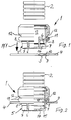
- FIG. 1 One designated as a whole by 1, particularly well in FIG. 1, but also in Fig. 3 recognizable in a modified form fitting for attaching elongated bodies, in the exemplary embodiment to Attaching a corrugated hose 2 to an opening 3, for example at an opening or perforation in a wall 4 for example a housing or the like.
- connection fitting 1 has one in the arrow Pf1 in Fig. 1 indicated insertion axially projecting Fastening projection 5, which by substantially in the axial Slots 6 are divided into holding tongues 7, on the outside of which radially projecting retaining projections 8 are arranged when inserting the fastening projection 5 and thus the holding tongues 7 in the opening 3 according to Fig.2 and 3 get into the holding position behind the edge 9 of this perforation 3, in which the retaining projections 8 engage behind this edge 9.
- the stop is according to Fig.2 and 3, as far as it is the immediate System on the opening edge 10 relates to a rubber-elastic ring 11, which is on an inside outward slant from the opening 3 away widening surface 12 of the connection fitting 1 supports the So stop is total of this inclined surface 12 and ring 11 formed thereon. Opposite a starting position 1 is due to this arrangement of the ring 11 under possible enlargement of its diameter against a restoring force compressible on this inclined surface 12 and in axial Slidable in the direction.
- connection fitting must 1 can only be inserted into opening 3 with a slightly greater force, until the retaining projections 8 behind the edge 9 to be gripped arrive and locked there, then the ring 11th correspondingly more deformed and due to the inclined surface 12 below Under certain circumstances, something is expanded, if it is on this Sloping surface 12 is shifted somewhat axially.
- a special screw sleeve or the like as a counter-stop and to adjust the wall thickness is not necessary.
- the abutment ring 11 is an O-ring that is inexpensive and available in almost any size for automatic adjustment to different wall thicknesses at the same time a seal of the connection fitting in the area the opening 3 on this wall. So this ring has 11 an advantageous double function.
- the inclined support surface 12 has a straight line Surface lines so that it forms a truncated cone. If necessary, however, it could also be convex, at least in some areas or be concave to widen the stop ring 11 to be designed disproportionately or disproportionately depending on the wall thickness.
- the inner longitudinal cavity 13 of the connection fitting continues into the Area of the fastening projections 8 and beyond.
- the elongated body is sufficient in the position of use, i.e. in the Embodiment of the corrugated hose 2 between the retaining tongues 7 and thereby improves their anchoring because they are also under dynamic loads or under a diagonal pull not out of their Rest position can be withdrawn, but through the Corrugated hose 2 at such a deformation in the opening direction be prevented.
- connection fitting 1 for attaching elongated bodies such as Hoses, corrugated hoses 2, but also pipes or cables, on one Opening 3 for example in a wall 4 of a housing has in Insert direction Pf1 an axially projecting fastening projection 5, which is divided by slots 6 in retaining tongues 7, at their Outside, at least in the use position, approximately radially outwards protruding holding projections 8 are arranged.
- the retaining tongues 7 are when inserting the fastening projection 5 into the opening 3 or the like breakthrough through the edge 10 radially inwards deformable against a restoring force and reach behind the edge 9 in its holding position, in which the holding projections 8 this Reach behind edge 9.
- a stop arranged in the use position on the engaging edge 9 of the opening 3 opposite, ie in Insert direction of front opening edge 10 is present. That attack is a rubber elastic ring 11, which is on an inside out outside obliquely from the opening 3 widening surface 12 of the Connection fitting 1 supports and under elastic deformation and / or increasing its diameter against a restoring force can be pressed against this surface 12 and / or on this inclined surface 12 is displaceable in the axial direction.
- This can be elastic flexible ring 11 have a sealing function at the same time.
Abstract
Eine Anschlußarmatur (1) zum Befestigen von länglichen Körpern wie Schläuchen, Wellschläuchen (2), aber auch Rohren oder Kabeln, an einer Öffnung (3) zum Beispiel in einer Wandung (4) eines Gehäuses hat in Einsteckrichtung (Pf1) einen axial vorstehenden Befestigungsvorsprung (5), der durch Schlitze (6) in Haltezungen (7) aufgeteilt ist, an deren Außenseite zumindest in Gebrauchsstellung etwa radial nach außen vorstehende Haltevorsprünge (8) angeordnet sind. Die Haltezungen (7) sind beim Einschieben des Befestigungsvorsprunges (5) in die Öffnung (3) oder dergleichen Durchbruch durch deren Rand (10) radial nach innen gegen eine Rückstellkraft verformbar und gelangen hinter dem Rand (9) in ihre Halteposition, in welcher die Haltevorsprünge (8) diesen Rand (9) hintergreifen. Mit Abstand zu den Haltevorsprüngen (8) ist ein Anschlag angeordnet, der in Gebrauchsstellung an dem dem hintergriffenen Rand (9) der Öffnung (3) gegenüberliegenden, also in Einsteckrichtung vorderen Öffnungsrand (10) anliegt. Dieser Anschlag ist ein gummielastischer Ring (11), der auf einer sich von innen nach außen schräg von der Öffnung (3) weg erweiternden Fläche (12) der Anschlußarmatur (1) abstützt und unter elastischer Verformung und/oder unter Vergrößerung seines Durchmessers gegen eine Rückstellkraft an diese Fläche (12) anpreßbar und/oder auf dieser schrägen Fläche (12) in axialer Richtung verschiebbar ist. Dabei kann dieser elastisch nachgiebige Ring (11) gleichzeitig eine Abdichtfunktion haben. <IMAGE>A connection fitting (1) for fastening elongated bodies such as hoses, corrugated hoses (2), but also pipes or cables, to an opening (3), for example in a wall (4) of a housing, has an axially projecting fastening projection in the direction of insertion (Pf1) (5), which is divided by slots (6) into holding tongues (7), on the outside of which, at least in the position of use, there are holding projections (8) projecting radially outwards. The retaining tongues (7) are deformable radially inward against a restoring force when the fastening projection (5) is pushed into the opening (3) or the like opening through the edge (10) thereof and reach their holding position behind the edge (9), in which the Holding projections (8) reach behind this edge (9). A stop is arranged at a distance from the holding projections (8), which in the position of use rests on the opening edge (10) opposite the engaging edge (9) of the opening (3), that is to say in the direction of insertion. This stop is a rubber-elastic ring (11) which is supported on a surface (12) of the connection fitting (1) which widens obliquely from the inside (3) away from the opening (3) and with elastic deformation and / or increasing its diameter against one Restoring force can be pressed against this surface (12) and / or displaceable in the axial direction on this inclined surface (12). This resilient ring (11) can also have a sealing function. <IMAGE>
Description
Die Erfindung betrifft eine Anschlußarmatur zum Befestigen von länglichen Körpern, beispielsweise von Schläuchen, Wellschläuchen, Rohren, Kabeln oder dergleichen, an einer Öffnung, insbesondere an einem Durchbruch oder einer Lochung, zum Beispiel in einer Wandung eines Gehäuses oder dergleichen, wobei die Anschlußarmatur einen in Einsteckrichtung axial vorstehenden Befestigungsvorsprung aufweist, der durch im wesentlichen in axialer Richtung verlaufende Schlitze in Haltezungen aufgeteilt ist, an deren Außenseite zumindest in Gebrauchsstellung etwa radial nach außen vorstehende Haltevorsprünge angeordnet sind, wobei die Haltezungen beim Einschieben des Befestigungsvorsprunges in die Öffnung, den Durchbruch oder dergleichen Lochung hinter dem Rand der Öffnung in die Halteposition gelangen, in welcher sie diesen Rand zumindest teilweise hintergreifen, wobei mit Abstand zu den Haltevorsprüngen wenigstens ein Anschlag angeordnet ist, der in Gebrauchsstellung an dem dem hintergriffenen Rand der Öffnung gegenüberliegenden Öffnungsrand anliegt.The invention relates to a connection fitting for attaching elongated bodies, for example of hoses, corrugated hoses, Pipes, cables or the like, at an opening, in particular on an opening or perforation, for example in a wall a housing or the like, the connection fitting a axially protruding fastening projection in the insertion direction has, which by substantially in the axial direction Slots are divided into retaining tongues, at least on the outside holding projections protruding radially outwards in the use position are arranged, the retaining tongues when inserted of the fastening projection in the opening, the opening or same perforation behind the edge of the opening in the holding position get in which they reach behind this edge at least partially, being at least one at a distance from the holding projections Stop is arranged, which in the use position on the gripped edge of the opening opposite the opening edge is present.
Eine derartige Anschlußarmatur ist beispielsweise aus der US-Patentschrift
5 068 496 bekannt. Um dabei verschiedene Dicken oder
Stärken der Wandung des Gehäuses bzw. unterschiedliche Abstände
der beidseitigen Ränder der Öffnung ausgleichen zu können, ist an
der Anschlußarmatur eine Überwurfmutter außenseitig verschraubbar
und dadurch axial verstellbar vorgesehen, deren der Gehäusewandung
zugewandte Stirnseite einen verstellbaren Anschlag bildet. Je nach
Dicke oder Stärke der Wandung kann diese Überwurfmutter mehr oder
weniger weit in axialer Richtung durch die Schraubbewegung verstellt
werden, so daß dadurch die Öffnungsränder einerseits zwischen den
Haltevorsprüngen des Befestigungsvorsprunges und andererseits dieser
Überwurfmutter eingespannt werden. Dies stellt eine relativ
aufwendige Konstruktion sowohl hinsichtlich Herstellung als auch
Montage dar. Die eigentliche Anschlußarmatur benötigt dabei nämlich
außenseitig ein Gewinde und darüber hinaus die auf diesem Gewinde
verschraubbare Überwurfmutter und ferner ist bei der Montage die
entsprechende Einstellung dieser Überwurfmutter in die richtige
Lage erforderlich.Such a connection fitting is, for example, from the US
Es besteht deshalb die Aufgabe, eine Anschlußarmatur der eingangs genannten Art zu schaffen, die ebenfalls an Öffnungen, Lochungen oder Durchbrüchen von Gehäusewandungen mit unterschiedlichen Wandstärken anbringbar ist, ohne daß ein außenseitiges Gewinde und eine Verschraubung erforderlich sind.There is therefore the task of a connection fitting at the beginning to create the type mentioned, which also has openings, perforations or breakthroughs of housing walls with different Wall thicknesses can be attached without an outside thread and a screw connection is required.
Die Lösung dieser scheinbar widersprüchlichen Aufgabe besteht darin, daß der Anschlag ein elastischer oder gummielastischer Ring ist, der auf einer sich von innen nach außen schräg von der Öffnung weg erweiternden Fläche der Anschlußarmatur abgestützt und unter elastischer Vergrößerung seines Durchmessers gegen seine Rückstellkraft auf dieser schrägen Fläche in axialer Richtung bewegbar oder verschiebbar ist. Der Anschlag ist also durch die Kombination der sich in Gebrauchsstellung schräg von der Öffnung weg erweiternden Fläche mit dem zwischen der Gehäusewandung und dieser schrägen Fläche angeordneten elastischen Ring gebildet. Je dicker die Gehäusewandung ist, um so mehr wird der Ring auf der schrägen Fläche beim axialen Einstecken des Befestigungsvorsprunges zurückgedrängt und dabei gleichzeitig hinsichtlich seines Umfanges gegen seine elastische Rückstellkraft aufgeweitet. Gleichzeitig kann er dabei auch in axialer Richtung noch etwas gegen seine Elastizität und Rückstellkraft zusammengedrückt werden. Da ein gummielastischer Ring beim Aufweiten hinsichtlich seines eigenen Querschnittes etwas abnimmt, gleichzeitig aber der Widerstand gegen eine weitere Verformung zunimmt, entsteht ein fester Anschlag, der automatisch unterschiedliche Wandstärken ausgleicht. In besonders vorteilhafter Weise werden dabei durch diesen gummielastischen Ring gleichzeitig Unregelmäßigkeiten von Wandstärken überbrückt oder ebenfalls ausgeglichen.The solution to this seemingly contradictory task is to that the stop is an elastic or rubber-elastic ring, the one on the inside out obliquely away from the opening expanding area of the connection fitting supported and under elastic increase of its diameter against its restoring force movable on this inclined surface in the axial direction or is movable. So the stop is through the combination of the expanding obliquely away from the opening in the use position Area with that between the housing wall and this sloping surface arranged elastic ring formed. The thicker the housing wall is, the more the ring is on the inclined surface in the axial Pushing the fastening projection pushed back while doing so at the same time in terms of its size against its elastic Restoring force expanded. At the same time he can also in axial direction something against its elasticity and restoring force be squeezed together. Since a rubber elastic ring at Widening slightly decreases with regard to its own cross-section, at the same time, however, the resistance to further deformation increases, there is a firm stop that automatically different Balances wall thicknesses. In a particularly advantageous way are simultaneously through this rubber elastic ring Irregularities of wall thicknesses bridged or also balanced.
Eine besonders preiswerte Anordnung ergibt sich, wenn der Widerlagerring ein O-Ring ist. Solche O-Ringe sind als handelsübliche Dichtringe sehr preiswert zu erhalten und erlauben eine gewisse Aufdehnung und Verpressung, so daß sich eine sehr preiswerte Lösung ergibt. Darüber hinaus ist ein solcher O-Ring aus einem gummielastischen Werkstoff gefertigt, kann also entsprechend gut verformt und angepaßt werden und übertrifft dadurch einen beispielsweise aus einer oder mehreren Drahtwindungen bestehenden Ring. Ferner läßt sich ein solcher O-Ring aufgrund des runden oder kreisrunden Querschnittes - quer oder radial zu seinem Umfang verlaufend - besonders gut auf einer schrägen Fläche oder Stützfläche in axialer Richtung unter gleichzeitiger Aufweitung seines Umfanges verschieben. Dabei bleibt der von ihm gebildete Anschlagringbereich, von der Durchmesservergrößerung abgesehen, praktisch unverändert.A particularly inexpensive arrangement results if the Abutment ring is an O-ring. Such O-rings are considered commercially available Sealing rings very cheap to get and allow a certain Expansion and compression, so that there is a very inexpensive solution results. In addition, such an O-ring is made of a rubber-elastic Manufactured material, so it can be deformed accordingly be adjusted and thereby surpasses one, for example one or more coils of wire. Furthermore lets such an O-ring due to the round or circular Cross-section - transverse or radial to its circumference - particularly well on an inclined surface or support surface in the axial Shift direction while expanding its scope. The stop ring area formed by him remains from the Apart from enlarging the diameter, practically unchanged.
Die schräge Stützfläche für den Widerlagerring kann geradlinige und/oder gekrümmte Mantellinien aufweisen, so daß sie einen Kegelstumpf bildet, der gegebenenfalls zumindest bereichsweise konvex und/oder konkav ist.The sloping support surface for the abutment ring can be straight and / or have curved surface lines so that they have a Truncated cone, which may be convex at least in some areas and / or is concave.
Hat die Stützfläche insgesamt die Form eine Kegelstumpfes, ergibt sich eine gleichbleibende Aufweitung des Widerlagerringes bei seiner axialen Verstellung. Durch teils geradlinige, teils gekrümmte Mantellinien, die dabei eine ballige oder eine eingesenkte Fläche bilden können, kann jedoch die Stützfläche so gestaltet sein, daß die Aufweitung des Widerlagerringes bei zunehmender Wandstärke der Gehäusewandung über- oder unterproportional verläuft, zum Beispiel abhängig von der Elastizität des Werkstoffes des Widerlagerringes. Beispielsweise könnte die Stützfläche etwas ballig gekrümmt sein, so daß ihr Schrägungswinkel in axialer Richtung bei zunehmendem Radius immer geringer wird, also der Widerlagerring bei größeren Wandstärken immer weniger aufgeweitet werden muß, um die gewünschte Anpassung zu ermöglichen.If the support surface has the shape of a truncated cone, the result is there is a constant expansion of the abutment ring at its axial adjustment. Through partly straight, partly curved Surface lines, which are a spherical or a sunken surface can form, however, the support surface can be designed so that the expansion of the abutment ring with increasing wall thickness Housing wall runs disproportionately or disproportionately, for example depending on the elasticity of the material of the abutment ring. For example, the support surface could be slightly curved, so that their helix angle increases in the axial direction Radius becomes smaller and smaller, i.e. the abutment ring with larger ones Wall thicknesses need to be expanded less and less to get the desired Allow customization.
Die Innenlängshöhlung der Anschlußarmatur kann bis in den Befestigungsvorsprung oder durch diesen hindurch fortgesetzt sein und der längliche Körper kann in Gebrauchsstellung bis zwischen die Haltezungen reichen und/oder gegenüber diesen Haltezungen axial überstehen. Bei einer solchen Gestaltungbewirkt der längliche Körper in Gebrauchsstellung eine Fixierung der Haltezungen in ihrer Halte-und Rastposition, verriegelt also die Anschlußarmatur gegen ein ungewolltes Lösen, was zum Beispiel dann zweckmäßig ist, wenn die Anschlußarmatur und das sie aufnehmende Gehäuse dynamischen Belastungen unterliegen.The interior longitudinal concavity of the connection fitting can extend into the Fastening projection or be continued through this and the elongated body can in the use position until between the retaining tongues extend axially and / or relative to these retaining tongues survive. With such a design, the elongated body acts in the position of use a fixation of the holding tongues in their holding and Rest position, so locks the connection fitting against unwanted loosening, which is useful, for example, when the Connection fitting and the housing receiving it dynamic Subject to charges.
Insgesamt ergibt sich eine Anschlußarmatur, die sehr einfach in ihrem Aufbau ist, weil die Anpassung an unterschiedliche Wandstärken durch einen gummielastischen Anschlagring praktisch automatisch erfolgen kann, wobei ein besonderer zusätzlicher Vorteil darin besteht, daß der Anschlagring gleichzeitig eine Abdichtung der Armatur gegenüber der Gehäuseöffnung ergibt. Auf diese Weise erhält der Anschlagring eine Doppelfunktion, weil er einerseits die Dickenanpassung erlaubt und dabei gleichzeitig eine Dichtwirkung ausübt.Overall, there is a connection fitting that is very simple in their structure is because they adapt to different wall thicknesses practically automatically thanks to a rubber-elastic stop ring can take place, with a particular additional advantage in it there is that the stop ring simultaneously seals the Fitting opposite the housing opening results. That way gets the stop ring has a double function, because on the one hand the Adjustment of thickness allowed and at the same time a sealing effect exercises.
Nachstehend sind Ausführungsbeispiele der Erfindung anhand der Zeichnung näher beschrieben. Es zeigt in zum Teil schematisierter Darstellung:
- Fig.1
- eine zur Hälfte im Längsschnitt und zur anderen Hälfte in Seitenansicht dargestellte Anschlußarmatur gemäß der Erfindung vor ihrer Befestigung an einer mit einer Öffnung versehenen Gehäusewandung und vor dem Einfügen und Fixieren eines Wellschlauches,
- Fig.2
- eine der Fig.1 entsprechende Darstellung der Anschlußarmatur in Gebrauchsstellung, das heißt nach dem Einstecken in eine Öffnung einer Gehäusewandung oder dergleichen und nach dem Befestigen eines länglichen Körpers in Form eines Wellschlauches an und in dieser Anschlußarmatur sowie
- Fig.3
- eine abgewandelte Ausführungsform einer an einer Öffnung einer Gehäusewandung bereits eingesteckten und festgelegten Anschlußarmatur, in welche ein länglicher Körper in Form eines Wellschlauches noch zu seiner Befestigung einsteckbar ist.
- Fig. 1
- a connecting fitting according to the invention, half in longitudinal section and the other half in side view, before it is attached to an opening provided with an opening in the housing and before the insertion and fixing of a corrugated hose,
- Fig. 2
- one of the Fig.1 corresponding representation of the connection fitting in the position of use, that is after plugging into an opening of a housing wall or the like and after attaching an elongated body in the form of a corrugated hose on and in this connection fitting and
- Fig. 3
- a modified embodiment of a connection fitting already inserted and fixed into an opening of a housing wall, into which an elongated body in the form of a corrugated hose can still be inserted for its attachment.
Bei den nachfolgend beschriebenen Ausführungsbeispielen erhalten hinsichtlich ihrer Funktion übereinstimmende oder ähnliche Teile übereinstimmende Bezugszahlen.Obtained in the exemplary embodiments described below parts that are the same or similar in function matching reference numbers.
Eine im ganzen mit 1 bezeichnete, besonders gut in Fig. 1, aber auch
in Fig.3 in abgewandelter Form erkennbare Anschlußarmatur dient
zum Befestigen von länglichen Körpern, im Ausführungsbeispiel zum
Befestigen eines Wellschlauches 2, an einer Öffnung 3, zum Beispiel
an einem Durchbruch oder einer Lochung in einer Wandung 4
beispielsweise eines Gehäuses oder dergleichen.One designated as a whole by 1, particularly well in FIG. 1, but also
in Fig. 3 recognizable in a modified form fitting
for attaching elongated bodies, in the exemplary embodiment to
Attaching a
Die Anschlußarmatur 1 weist dabei einen in der durch den Pfeil Pf1
in Fig. 1 angedeuteten Einsteckrichtung axial vorstehenden
Befestigungsvorsprung 5 auf, der durch im wesentlichen in axialer
Richtung verlaufende Schlitze 6 in Haltezungen 7 aufgeteilt ist,
an deren Außenseite radial nach außen vorstehende Haltevorsprünge
8 angeordnet sind, die beim Einschieben des Befestigungsvorsprunges
5 und damit der Haltezungen 7 in die Öffnung 3 gemäß Fig.2 und 3
hinter den Rand 9 dieser Lochung 3 in Halteposition gelangen, in
welcher die Haltevorsprünge 8 diesen Rand 9 hintergreifen. Sie haben
dabei im Ausführungsbeispiel einen etwa sägezahnartigen Querschnitt,
das heißt entgegen der Einsteckrichtung nimmt ihre Höhe allmählich
bis zu ihrer größten radialen Abmessung zu, um dann relativ steil
bzw. in einer radialen Ebene liegend abzufallen, wobei dieser steile
Abfall mit dem Lochungsrand 9 in Gebrauchsstellung in Wirkverbindung
ist.The connection fitting 1 has one in the arrow Pf1
in Fig. 1 indicated insertion axially projecting
Mit Abstand zu den Haltevorsprüngen 8 und deren steiler Anschlagfläche
ist ein noch näher zu beschreibender Anschlag angeordnet,
der in Gebrauchsstellung an dem dem hintergriffenen Rand 9 der
Öffnung 3 gegenüberliegenden Öffnungsrand 10 anliegt, wie es die
Figuren 2 und 3 zeigen.At a distance from the
Der Anschlag ist dabei gemäß Fig.2 und 3, soweit es die unmittelbare
Anlage an dem Öffnungsrand 10 betrifft, ein gummielastischer Ring
11, der auf einer sich von innen nach außen schräg von der Öffnung
3 weg erweiternden Fläche 12 der Anschlußarmatur 1 abstützt Der
Anschlag wird also insgesamt von dieser Schrägfläche 12 und dem
daran anliegenden Ring 11 gebildet. Gegenüber einer Ausgangsstellung
gemäß Fig.1 ist aufgrund dieser Anordnung der Ring 11 unter
eventueller Vergrößerung seines Durchmessers gegen eine Rückstellkraft
auf dieser schrägen Fläche 12 zusammendrückbar und in axialer
Richtung etwas verschiebbar.The stop is according to Fig.2 and 3, as far as it is the immediate
System on the
Gegenüber den Darstellungen gemäß Fig. 2 und 3 wird eine solche axiale
stärkere Verstellung des Widerlagerringes 11 dann erfolgen, wenn
die Dicke der Wandung 4 größer ist, so daß also aufgrund der
Elastizität des Ringes 11 und der Schrägfläche 12, deren kleinster
Durchmesser etwas in den Ring 11 eingreifen kann, eine Anpassung
an unterschiedliche Dicken oder Stärken der Wand 4 selbsttätig
möglich ist. Ist die Wand 4 etwas dicker, muß die Anschlußarmatur
1 nur mit etwas größerer Kraft in die Öffnung 3 eingesteckt werden,
bis die Haltevorsprünge 8 hinter den zu hintergreifenden Rand 9
gelangen und dort verrastet werden, wobei dann der Ring 11
entsprechend stärker verformt und aufgrund der Schrägfläche 12 unter
Umständen auch etwas aufgeweitet wird, wenn er nämlich auf dieser
Schrägfläche 12 etwas axial verschoben wird.Compared to the representations according to FIGS. 2 and 3, such an axial
stronger adjustment of the
Einer besonderen Schraubhülse oder dergleichen als Gegenanschlag und zur Einstellung der Wanddicke ist also nicht erforderlich.A special screw sleeve or the like as a counter-stop and to adjust the wall thickness is not necessary.
Im Ausführungsbeispiel ist der Widerlagerring 11 ein O-Ring, der
preiswert in nahezu beliebigen Größen erhältlich ist und zusätzlich
zu der automatischen Anpassung an unterschiedliche Wandstärken
gleichzeitig auch eine Abdichtung der Anschlußarmatur im Bereich
der Öffnung 3 an dieser Wandung ergibt. Somit hat dieser Ring 11
eine vorteilhafte Doppelfunktion.In the exemplary embodiment, the
Die schräge Stützfläche 12 weist im Ausführungsbeispiel geradlinige
Mantellinien auf, so daß sie also einen Kegelstumpf bildet.
Gegebenenfalls könnte sie jedoch auch zumindest bereichsweise konvex
oder konkav gestaltet sein, um die Aufweitung des Anschlagringes
11 je nach Wanddicke über- oder unterproportional zu gestalten.In the exemplary embodiment, the
Die Innenlängshöhlung 13 der Anschlußarmatur setzt sich bis in den
Bereich der Befestigungsvorsprünge 8 und noch darüber hinaus fort.
In Gebrauchsstellung reicht der längliche Körper, also im
Ausführungsbeispiel der Wellschlauch 2 also zwischen die Haltezungen
7 und verbessert dadurch deren Verankerung, weil sie auch unter
dynamischen Belastungen oder unter einem Schrägzug nicht aus ihrer
Rastposition zurückgezogen werden können, sondern durch den
Wellschlauch 2 an einer solchen Verformung in Öffnungsrichtung
gehindert werden.The inner
Im Ausführungsbeispiel gemäß Fig.1 und 2 enthalten dabei die
Haltezungen 7 an ihren Enden einen radial nach innen vorstehenden
Anschlag 14, an dem der Wellschlauch 2 in Gebrauchsstellung und
nach einer Verrastung mit einer innenseitigen Rippe 15 ansteht.1 and 2 contain the
Retaining tongues 7 a radially inwardly projecting at their
Im Ausführungsbeispiel gemäß Fig.3 ist ein Anschlag 13 an den
Haltezungen 7 zu einer innenseitigen Stützhülse 16 verlängert,
während die Verrastung mit dem Wellschlauch 2 durch eine an der
Anschlußarmatur oberhalb des Ringes 12 befindlichen Verankerung
15 in an sich bekannter Weise erfolgt.In the embodiment shown in Figure 3 is a
Die Anschlußarmatur 1 zum Befestigen von länglichen Körpern wie
Schläuchen, Wellschläuchen 2, aber auch Rohren oder Kabeln, an einer
Öffnung 3 zum Beispiel in einer Wandung 4 eines Gehäuses hat in
Einsteckrichtung Pf1 einen axial vorstehenden Befestigungsvorsprung
5, der durch Schlitze 6 in Haltezungen 7 aufgeteilt ist, an deren
Außenseite zumindest in Gebrauchsstellung etwa radial nach außen
vorstehende Haltevorsprünge 8 angeordnet sind. Die Haltezungen 7
sind beim Einschieben des Befestigungsvorsprunges 5 in die Öffnung
3 oder dergleichen Durchbruch durch deren Rand 10 radial nach innen
gegen eine Rückstellkraft verformbar und gelangen hinter dem Rand
9 in ihre Halteposition, in welcher die Haltevorsprünge 8 diesen
Rand 9 hintergreifen. Mit Abstand zu den Haltevorsprüngen 8 ist
ein Anschlag angeordnet, der in Gebrauchsstellung an dem dem
hintergriffenen Rand 9 der Öffnung 3 gegenüberliegenden, also in
Einsteckrichtung vorderen Öffnungsrand 10 anliegt. Dieser Anschlag
ist ein gummielastischer Ring 11, der auf einer sich von innen nach
außen schräg von der Öffnung 3 weg erweiternden Fläche 12 der
Anschlußarmatur 1 abstützt und unter elastischer Verformung und/oder
unter Vergrößerung seines Durchmessers gegen eine Rückstellkraft
an diese Fläche 12 anpreßbar und/oder auf dieser schrägen Fläche
12 in axialer Richtung verschiebbar ist. Dabei kann dieser elastisch
nachgiebige Ring 11 gleichzeitig eine Abdichtfunktion haben.The connection fitting 1 for attaching elongated bodies such as
Hoses,
Claims (4)
Applications Claiming Priority (2)
| Application Number | Priority Date | Filing Date | Title |
|---|---|---|---|
| DE19804719 | 1998-02-06 | ||
| DE19804719A DE19804719C1 (en) | 1998-02-06 | 1998-02-06 | Connecting fitting with axial protruding fixing projection fixing body e.g. hose |
Publications (3)
| Publication Number | Publication Date |
|---|---|
| EP0935087A2 true EP0935087A2 (en) | 1999-08-11 |
| EP0935087A3 EP0935087A3 (en) | 1999-12-15 |
| EP0935087B1 EP0935087B1 (en) | 2001-04-11 |
Family
ID=7856839
Family Applications (1)
| Application Number | Title | Priority Date | Filing Date |
|---|---|---|---|
| EP98121440A Expired - Lifetime EP0935087B1 (en) | 1998-02-06 | 1998-11-11 | Connecting device with anchoring protrusion |
Country Status (4)
| Country | Link |
|---|---|
| US (1) | US6082782A (en) |
| EP (1) | EP0935087B1 (en) |
| DE (2) | DE19804719C1 (en) |
| ES (1) | ES2158638T3 (en) |
Cited By (2)
| Publication number | Priority date | Publication date | Assignee | Title |
|---|---|---|---|---|
| US6722704B2 (en) | 2000-07-01 | 2004-04-20 | Anton Hummel Verwaltungs Gmbh | Connecting fitting with an elastic ring as a stop |
| US9528643B2 (en) | 2014-12-02 | 2016-12-27 | Cnh Industrial Canada, Ltd. | Air grommet connector |
Families Citing this family (22)
| Publication number | Priority date | Publication date | Assignee | Title |
|---|---|---|---|---|
| DE19828059C2 (en) * | 1998-06-24 | 2001-04-26 | Hummel Anton Verwaltung | Connection fitting with a fastening projection divided by slots in retaining tongues |
| SE512585C2 (en) * | 1998-08-17 | 2000-04-03 | Volvo Ab | Device and method for mounting an implement |
| US6359223B1 (en) * | 1999-08-11 | 2002-03-19 | Avaya Technology Corp. | Method and apparatus for making a high-pressure seal using cold shrink tubing |
| WO2002043211A1 (en) * | 2000-11-27 | 2002-05-30 | Terrence Geoffrey Walsh | A connector for electrical cables |
| DE10152331B4 (en) * | 2001-10-26 | 2011-02-17 | Murrplastik Systemtechnik Gmbh | hose mount |
| WO2003053729A2 (en) * | 2001-12-12 | 2003-07-03 | Martinrea Industries, Inc. | Spud assembly for a fuel tank |
| US6489560B1 (en) * | 2002-01-10 | 2002-12-03 | Wen-Chang Wu | Positioning device of lamp rod used in ceiling lamp of wire box |
| US6685243B1 (en) * | 2002-07-30 | 2004-02-03 | Shape Corporation | Bumper for reducing pedestrian injury |
| US7481436B2 (en) * | 2002-09-09 | 2009-01-27 | Dura Global Technologies, Inc. | Two part grommet with hard plastic locking prongs |
| US7104856B1 (en) * | 2004-06-15 | 2006-09-12 | Brunswick Corporation | Rigging apparatus for an outboard motor |
| US7461870B2 (en) * | 2004-06-23 | 2008-12-09 | Ibc Corporation | Connector for flexible electrical conduit |
| US7896404B2 (en) * | 2004-07-30 | 2011-03-01 | The Lamson & Sessions Co. | Tubular reducer fitting for electrical nonmetallic tubing |
| DE202005006242U1 (en) | 2005-04-14 | 2005-07-07 | Zürcher, Thomas Markus | Room ventilation equipment |
| DE202007003957U1 (en) | 2007-03-19 | 2008-07-31 | Anton Hummel Verwaltungs-Gmbh | Cable gland with threaded sleeve and union nut |
| US7963567B2 (en) * | 2007-04-27 | 2011-06-21 | Securus, Inc. | Anti-rotation pipe locator and holder |
| JP5134992B2 (en) * | 2008-02-01 | 2013-01-30 | 本田技研工業株式会社 | Outboard motor |
| DE102009021700A1 (en) | 2009-05-17 | 2010-11-18 | Hidde, Axel, Dipl.-Ing. | Universal quick-release fitting |
| ES2860685T3 (en) * | 2014-03-28 | 2021-10-05 | Heyco Products Corp | Liquid-tight pressure release |
| ES2912034T3 (en) * | 2014-03-31 | 2022-05-24 | Uponor Innovation Ab | Connection sleeve and manifold box |
| CN105743039A (en) * | 2014-12-09 | 2016-07-06 | 新绿股份有限公司 | Cable fixing device |
| US10240896B2 (en) * | 2015-03-12 | 2019-03-26 | Raytheon Company | Tube to bulkhead bonded joint design |
| PL233382B1 (en) * | 2017-03-01 | 2019-10-31 | Aic Spolka Akcyjna | Pipe fitting for connection of a pipeline with another device, preferably the heat exchanger connector pipe |
Citations (3)
| Publication number | Priority date | Publication date | Assignee | Title |
|---|---|---|---|---|
| US5068496A (en) * | 1990-10-31 | 1991-11-26 | Hubbell Incorporated | Snap-in connector |
| US5204499A (en) * | 1991-05-03 | 1993-04-20 | Hubbell Incorporated | Snap-in connector with integral spring |
| DE19647013A1 (en) * | 1996-02-19 | 1997-08-21 | Hauff Technik Gmbh & Co Kg | Sealing packing for insertion into a wall opening for the purpose of passing cables through |
Family Cites Families (4)
| Publication number | Priority date | Publication date | Assignee | Title |
|---|---|---|---|---|
| US3221572A (en) * | 1963-09-30 | 1965-12-07 | Illinois Tool Works | Cable fastener assembly |
| US3415549A (en) * | 1965-09-23 | 1968-12-10 | Newton L. Chatham | Cable housing anchoring unit |
| US3836269A (en) * | 1973-09-26 | 1974-09-17 | Illinois Tool Works | Cable sealing grommet |
| FR2635369B1 (en) * | 1988-08-09 | 1990-10-05 | Degremont | DEVICE FOR QUICK, SEALED CONNECTION OF TUBES |
-
1998
- 1998-02-06 DE DE19804719A patent/DE19804719C1/en not_active Expired - Fee Related
- 1998-11-11 EP EP98121440A patent/EP0935087B1/en not_active Expired - Lifetime
- 1998-11-11 DE DE59800620T patent/DE59800620D1/en not_active Expired - Lifetime
- 1998-11-11 ES ES98121440T patent/ES2158638T3/en not_active Expired - Lifetime
-
1999
- 1999-01-27 US US09/238,352 patent/US6082782A/en not_active Expired - Lifetime
Patent Citations (3)
| Publication number | Priority date | Publication date | Assignee | Title |
|---|---|---|---|---|
| US5068496A (en) * | 1990-10-31 | 1991-11-26 | Hubbell Incorporated | Snap-in connector |
| US5204499A (en) * | 1991-05-03 | 1993-04-20 | Hubbell Incorporated | Snap-in connector with integral spring |
| DE19647013A1 (en) * | 1996-02-19 | 1997-08-21 | Hauff Technik Gmbh & Co Kg | Sealing packing for insertion into a wall opening for the purpose of passing cables through |
Cited By (2)
| Publication number | Priority date | Publication date | Assignee | Title |
|---|---|---|---|---|
| US6722704B2 (en) | 2000-07-01 | 2004-04-20 | Anton Hummel Verwaltungs Gmbh | Connecting fitting with an elastic ring as a stop |
| US9528643B2 (en) | 2014-12-02 | 2016-12-27 | Cnh Industrial Canada, Ltd. | Air grommet connector |
Also Published As
| Publication number | Publication date |
|---|---|
| DE59800620D1 (en) | 2001-05-17 |
| EP0935087A3 (en) | 1999-12-15 |
| ES2158638T3 (en) | 2001-09-01 |
| DE19804719C1 (en) | 1999-04-08 |
| US6082782A (en) | 2000-07-04 |
| EP0935087B1 (en) | 2001-04-11 |
Similar Documents
| Publication | Publication Date | Title |
|---|---|---|
| EP0935087B1 (en) | Connecting device with anchoring protrusion | |
| DE19828059C2 (en) | Connection fitting with a fastening projection divided by slots in retaining tongues | |
| DE10032010C1 (en) | Connection fitting for a pipe etc. through a housing wall has a division near the angled support surface for the limit ring to allow for large wall thickness differences | |
| EP0733844B1 (en) | Conduit connection device | |
| DE3424675C2 (en) | Hose coupling | |
| EP1228331B1 (en) | Connecting fitting for peripherally ribbed longitudinal bodies with a locking retaining projecting element | |
| DE19751361A1 (en) | Connection element for pipes or hoses | |
| EP0465896A1 (en) | Connector device for corrugated pipe and hose | |
| CH645448A5 (en) | CONNECTION FITTING WITH FLEXIBLE CORRUGATED HOSE. | |
| EP1065426A2 (en) | Connecting device for the fastening of elongated bodies | |
| DE2832614A1 (en) | CONNECTING PIECE FOR PIPING | |
| EP0943856A2 (en) | Connecting device with mounting protrusion | |
| DE602005005609T2 (en) | Connecting sleeve for pipe branches | |
| DE1962687A1 (en) | System with enclosed mother and cage | |
| DE1600466B2 (en) | FITTED PIPE FOR PLASTIC PIPES | |
| DE3225172A1 (en) | Connecting nipple for plastic pipes in a plug-in connection | |
| DE202005004524U1 (en) | Plug-in connection for joining pipe to fitting, comprising clamping ring with additional projections on outer surface | |
| DE19702552C2 (en) | Hose socket, especially for corrugated pipes | |
| DE102010023920B4 (en) | Sealing ring for a telescopic vacuum cleaner suction tube | |
| AT409166B (en) | ELASTOMER CUFF FOR SEALING CONNECTION OF TWO PIPING | |
| EP1188978B1 (en) | Plug-in sleeve for connecting plastic pipes | |
| DE3033172C2 (en) | ||
| DE3426579C2 (en) | ||
| DE3721354A1 (en) | Connection fitting for flexible corrugated hoses | |
| DE102004016597A1 (en) | Method for joining flexible pipe to pipe connecting unit, using spreading tool acting on inner surface of sleeve |
Legal Events
| Date | Code | Title | Description |
|---|---|---|---|
| PUAI | Public reference made under article 153(3) epc to a published international application that has entered the european phase |
Free format text: ORIGINAL CODE: 0009012 |
|
| AK | Designated contracting states |
Kind code of ref document: A2 Designated state(s): CH DE ES FR GB IT LI SE |
|
| AX | Request for extension of the european patent |
Free format text: AL;LT;LV;MK;RO;SI |
|
| PUAL | Search report despatched |
Free format text: ORIGINAL CODE: 0009013 |
|
| AK | Designated contracting states |
Kind code of ref document: A3 Designated state(s): AT BE CH CY DE DK ES FI FR GB GR IE IT LI LU MC NL PT SE |
|
| AX | Request for extension of the european patent |
Free format text: AL;LT;LV;MK;RO;SI |
|
| RIC1 | Information provided on ipc code assigned before grant |
Free format text: 6F 16L 25/00 A, 6F 16L 37/084 B, 6F 16L 37/00 B, 6F 16L 5/02 B, 6H 02G 3/06 B |
|
| 17P | Request for examination filed |
Effective date: 19991111 |
|
| AKX | Designation fees paid |
Free format text: CH DE ES FR GB IT LI SE |
|
| GRAG | Despatch of communication of intention to grant |
Free format text: ORIGINAL CODE: EPIDOS AGRA |
|
| 17Q | First examination report despatched |
Effective date: 20001116 |
|
| GRAG | Despatch of communication of intention to grant |
Free format text: ORIGINAL CODE: EPIDOS AGRA |
|
| GRAG | Despatch of communication of intention to grant |
Free format text: ORIGINAL CODE: EPIDOS AGRA |
|
| GRAH | Despatch of communication of intention to grant a patent |
Free format text: ORIGINAL CODE: EPIDOS IGRA |
|
| GRAH | Despatch of communication of intention to grant a patent |
Free format text: ORIGINAL CODE: EPIDOS IGRA |
|
| GRAA | (expected) grant |
Free format text: ORIGINAL CODE: 0009210 |
|
| AK | Designated contracting states |
Kind code of ref document: B1 Designated state(s): CH DE ES FR GB IT LI SE |
|
| REG | Reference to a national code |
Ref country code: CH Ref legal event code: EP |
|
| REF | Corresponds to: |
Ref document number: 59800620 Country of ref document: DE Date of ref document: 20010517 |
|
| REG | Reference to a national code |
Ref country code: CH Ref legal event code: NV Representative=s name: HANS RUDOLF GACHNANG PATENTANWALT |
|
| ITF | It: translation for a ep patent filed |
Owner name: ING. ZINI MARANESI & C. S.R.L. |
|
| GBT | Gb: translation of ep patent filed (gb section 77(6)(a)/1977) |
Effective date: 20010718 |
|
| ET | Fr: translation filed | ||
| REG | Reference to a national code |
Ref country code: ES Ref legal event code: FG2A Ref document number: 2158638 Country of ref document: ES Kind code of ref document: T3 |
|
| REG | Reference to a national code |
Ref country code: GB Ref legal event code: IF02 |
|
| PLBE | No opposition filed within time limit |
Free format text: ORIGINAL CODE: 0009261 |
|
| STAA | Information on the status of an ep patent application or granted ep patent |
Free format text: STATUS: NO OPPOSITION FILED WITHIN TIME LIMIT |
|
| 26N | No opposition filed | ||
| PGFP | Annual fee paid to national office [announced via postgrant information from national office to epo] |
Ref country code: ES Payment date: 20130910 Year of fee payment: 16 |
|
| PGFP | Annual fee paid to national office [announced via postgrant information from national office to epo] |
Ref country code: FR Payment date: 20130827 Year of fee payment: 16 |
|
| PGFP | Annual fee paid to national office [announced via postgrant information from national office to epo] |
Ref country code: GB Payment date: 20131122 Year of fee payment: 16 Ref country code: CH Payment date: 20131130 Year of fee payment: 16 Ref country code: SE Payment date: 20131122 Year of fee payment: 16 |
|
| PGFP | Annual fee paid to national office [announced via postgrant information from national office to epo] |
Ref country code: IT Payment date: 20131127 Year of fee payment: 16 |
|
| REG | Reference to a national code |
Ref country code: CH Ref legal event code: NV Representative=s name: GACHNANG AG PATENTANWAELTE, CH |
|
| REG | Reference to a national code |
Ref country code: CH Ref legal event code: PL Ref country code: SE Ref legal event code: EUG |
|
| GBPC | Gb: european patent ceased through non-payment of renewal fee |
Effective date: 20141111 |
|
| PG25 | Lapsed in a contracting state [announced via postgrant information from national office to epo] |
Ref country code: SE Free format text: LAPSE BECAUSE OF NON-PAYMENT OF DUE FEES Effective date: 20141112 Ref country code: LI Free format text: LAPSE BECAUSE OF NON-PAYMENT OF DUE FEES Effective date: 20141130 Ref country code: CH Free format text: LAPSE BECAUSE OF NON-PAYMENT OF DUE FEES Effective date: 20141130 |
|
| REG | Reference to a national code |
Ref country code: FR Ref legal event code: ST Effective date: 20150731 |
|
| PG25 | Lapsed in a contracting state [announced via postgrant information from national office to epo] |
Ref country code: GB Free format text: LAPSE BECAUSE OF NON-PAYMENT OF DUE FEES Effective date: 20141111 |
|
| PG25 | Lapsed in a contracting state [announced via postgrant information from national office to epo] |
Ref country code: FR Free format text: LAPSE BECAUSE OF NON-PAYMENT OF DUE FEES Effective date: 20141201 |
|
| REG | Reference to a national code |
Ref country code: ES Ref legal event code: FD2A Effective date: 20151229 |
|
| PG25 | Lapsed in a contracting state [announced via postgrant information from national office to epo] |
Ref country code: IT Free format text: LAPSE BECAUSE OF NON-PAYMENT OF DUE FEES Effective date: 20141111 |
|
| PG25 | Lapsed in a contracting state [announced via postgrant information from national office to epo] |
Ref country code: ES Free format text: LAPSE BECAUSE OF NON-PAYMENT OF DUE FEES Effective date: 20141112 |
|
| PGFP | Annual fee paid to national office [announced via postgrant information from national office to epo] |
Ref country code: DE Payment date: 20161213 Year of fee payment: 19 |
|
| REG | Reference to a national code |
Ref country code: DE Ref legal event code: R119 Ref document number: 59800620 Country of ref document: DE |
|
| PG25 | Lapsed in a contracting state [announced via postgrant information from national office to epo] |
Ref country code: DE Free format text: LAPSE BECAUSE OF NON-PAYMENT OF DUE FEES Effective date: 20180602 |