EP0931522A1 - Assembling set for shaft prostheses - Google Patents
Assembling set for shaft prostheses Download PDFInfo
- Publication number
- EP0931522A1 EP0931522A1 EP98810021A EP98810021A EP0931522A1 EP 0931522 A1 EP0931522 A1 EP 0931522A1 EP 98810021 A EP98810021 A EP 98810021A EP 98810021 A EP98810021 A EP 98810021A EP 0931522 A1 EP0931522 A1 EP 0931522A1
- Authority
- EP
- European Patent Office
- Prior art keywords
- prosthesis
- head
- stem
- trial
- prostheses
- Prior art date
- Legal status (The legal status is an assumption and is not a legal conclusion. Google has not performed a legal analysis and makes no representation as to the accuracy of the status listed.)
- Granted
Links
Images


Classifications
-
- A—HUMAN NECESSITIES
- A61—MEDICAL OR VETERINARY SCIENCE; HYGIENE
- A61F—FILTERS IMPLANTABLE INTO BLOOD VESSELS; PROSTHESES; DEVICES PROVIDING PATENCY TO, OR PREVENTING COLLAPSING OF, TUBULAR STRUCTURES OF THE BODY, e.g. STENTS; ORTHOPAEDIC, NURSING OR CONTRACEPTIVE DEVICES; FOMENTATION; TREATMENT OR PROTECTION OF EYES OR EARS; BANDAGES, DRESSINGS OR ABSORBENT PADS; FIRST-AID KITS
- A61F2/00—Filters implantable into blood vessels; Prostheses, i.e. artificial substitutes or replacements for parts of the body; Appliances for connecting them with the body; Devices providing patency to, or preventing collapsing of, tubular structures of the body, e.g. stents
- A61F2/02—Prostheses implantable into the body
- A61F2/30—Joints
- A61F2/46—Special tools or methods for implanting or extracting artificial joints, accessories, bone grafts or substitutes, or particular adaptations therefor
- A61F2/4684—Trial or dummy prostheses
-
- A—HUMAN NECESSITIES
- A61—MEDICAL OR VETERINARY SCIENCE; HYGIENE
- A61F—FILTERS IMPLANTABLE INTO BLOOD VESSELS; PROSTHESES; DEVICES PROVIDING PATENCY TO, OR PREVENTING COLLAPSING OF, TUBULAR STRUCTURES OF THE BODY, e.g. STENTS; ORTHOPAEDIC, NURSING OR CONTRACEPTIVE DEVICES; FOMENTATION; TREATMENT OR PROTECTION OF EYES OR EARS; BANDAGES, DRESSINGS OR ABSORBENT PADS; FIRST-AID KITS
- A61F2/00—Filters implantable into blood vessels; Prostheses, i.e. artificial substitutes or replacements for parts of the body; Appliances for connecting them with the body; Devices providing patency to, or preventing collapsing of, tubular structures of the body, e.g. stents
- A61F2/02—Prostheses implantable into the body
- A61F2/30—Joints
- A61F2/40—Joints for shoulders
-
- A—HUMAN NECESSITIES
- A61—MEDICAL OR VETERINARY SCIENCE; HYGIENE
- A61F—FILTERS IMPLANTABLE INTO BLOOD VESSELS; PROSTHESES; DEVICES PROVIDING PATENCY TO, OR PREVENTING COLLAPSING OF, TUBULAR STRUCTURES OF THE BODY, e.g. STENTS; ORTHOPAEDIC, NURSING OR CONTRACEPTIVE DEVICES; FOMENTATION; TREATMENT OR PROTECTION OF EYES OR EARS; BANDAGES, DRESSINGS OR ABSORBENT PADS; FIRST-AID KITS
- A61F2/00—Filters implantable into blood vessels; Prostheses, i.e. artificial substitutes or replacements for parts of the body; Appliances for connecting them with the body; Devices providing patency to, or preventing collapsing of, tubular structures of the body, e.g. stents
- A61F2/02—Prostheses implantable into the body
- A61F2/30—Joints
- A61F2/46—Special tools or methods for implanting or extracting artificial joints, accessories, bone grafts or substitutes, or particular adaptations therefor
- A61F2/4637—Special tools or methods for implanting or extracting artificial joints, accessories, bone grafts or substitutes, or particular adaptations therefor for connecting or disconnecting two parts of a prosthesis
-
- A—HUMAN NECESSITIES
- A61—MEDICAL OR VETERINARY SCIENCE; HYGIENE
- A61B—DIAGNOSIS; SURGERY; IDENTIFICATION
- A61B17/00—Surgical instruments, devices or methods, e.g. tourniquets
- A61B17/56—Surgical instruments or methods for treatment of bones or joints; Devices specially adapted therefor
- A61B17/58—Surgical instruments or methods for treatment of bones or joints; Devices specially adapted therefor for osteosynthesis, e.g. bone plates, screws, setting implements or the like
- A61B17/88—Osteosynthesis instruments; Methods or means for implanting or extracting internal or external fixation devices
- A61B17/8875—Screwdrivers, spanners or wrenches
-
- A—HUMAN NECESSITIES
- A61—MEDICAL OR VETERINARY SCIENCE; HYGIENE
- A61F—FILTERS IMPLANTABLE INTO BLOOD VESSELS; PROSTHESES; DEVICES PROVIDING PATENCY TO, OR PREVENTING COLLAPSING OF, TUBULAR STRUCTURES OF THE BODY, e.g. STENTS; ORTHOPAEDIC, NURSING OR CONTRACEPTIVE DEVICES; FOMENTATION; TREATMENT OR PROTECTION OF EYES OR EARS; BANDAGES, DRESSINGS OR ABSORBENT PADS; FIRST-AID KITS
- A61F2/00—Filters implantable into blood vessels; Prostheses, i.e. artificial substitutes or replacements for parts of the body; Appliances for connecting them with the body; Devices providing patency to, or preventing collapsing of, tubular structures of the body, e.g. stents
- A61F2/02—Prostheses implantable into the body
- A61F2/30—Joints
- A61F2/40—Joints for shoulders
- A61F2/4059—Humeral shafts
-
- A—HUMAN NECESSITIES
- A61—MEDICAL OR VETERINARY SCIENCE; HYGIENE
- A61F—FILTERS IMPLANTABLE INTO BLOOD VESSELS; PROSTHESES; DEVICES PROVIDING PATENCY TO, OR PREVENTING COLLAPSING OF, TUBULAR STRUCTURES OF THE BODY, e.g. STENTS; ORTHOPAEDIC, NURSING OR CONTRACEPTIVE DEVICES; FOMENTATION; TREATMENT OR PROTECTION OF EYES OR EARS; BANDAGES, DRESSINGS OR ABSORBENT PADS; FIRST-AID KITS
- A61F2/00—Filters implantable into blood vessels; Prostheses, i.e. artificial substitutes or replacements for parts of the body; Appliances for connecting them with the body; Devices providing patency to, or preventing collapsing of, tubular structures of the body, e.g. stents
- A61F2/02—Prostheses implantable into the body
- A61F2/30—Joints
- A61F2/46—Special tools or methods for implanting or extracting artificial joints, accessories, bone grafts or substitutes, or particular adaptations therefor
- A61F2/4603—Special tools or methods for implanting or extracting artificial joints, accessories, bone grafts or substitutes, or particular adaptations therefor for insertion or extraction of endoprosthetic joints or of accessories thereof
-
- A—HUMAN NECESSITIES
- A61—MEDICAL OR VETERINARY SCIENCE; HYGIENE
- A61F—FILTERS IMPLANTABLE INTO BLOOD VESSELS; PROSTHESES; DEVICES PROVIDING PATENCY TO, OR PREVENTING COLLAPSING OF, TUBULAR STRUCTURES OF THE BODY, e.g. STENTS; ORTHOPAEDIC, NURSING OR CONTRACEPTIVE DEVICES; FOMENTATION; TREATMENT OR PROTECTION OF EYES OR EARS; BANDAGES, DRESSINGS OR ABSORBENT PADS; FIRST-AID KITS
- A61F2/00—Filters implantable into blood vessels; Prostheses, i.e. artificial substitutes or replacements for parts of the body; Appliances for connecting them with the body; Devices providing patency to, or preventing collapsing of, tubular structures of the body, e.g. stents
- A61F2/02—Prostheses implantable into the body
- A61F2/30—Joints
- A61F2002/30001—Additional features of subject-matter classified in A61F2/28, A61F2/30 and subgroups thereof
- A61F2002/30316—The prosthesis having different structural features at different locations within the same prosthesis; Connections between prosthetic parts; Special structural features of bone or joint prostheses not otherwise provided for
- A61F2002/30329—Connections or couplings between prosthetic parts, e.g. between modular parts; Connecting elements
- A61F2002/30331—Connections or couplings between prosthetic parts, e.g. between modular parts; Connecting elements made by longitudinally pushing a protrusion into a complementarily-shaped recess, e.g. held by friction fit
- A61F2002/30378—Spherically-shaped protrusion and recess
-
- A—HUMAN NECESSITIES
- A61—MEDICAL OR VETERINARY SCIENCE; HYGIENE
- A61F—FILTERS IMPLANTABLE INTO BLOOD VESSELS; PROSTHESES; DEVICES PROVIDING PATENCY TO, OR PREVENTING COLLAPSING OF, TUBULAR STRUCTURES OF THE BODY, e.g. STENTS; ORTHOPAEDIC, NURSING OR CONTRACEPTIVE DEVICES; FOMENTATION; TREATMENT OR PROTECTION OF EYES OR EARS; BANDAGES, DRESSINGS OR ABSORBENT PADS; FIRST-AID KITS
- A61F2/00—Filters implantable into blood vessels; Prostheses, i.e. artificial substitutes or replacements for parts of the body; Appliances for connecting them with the body; Devices providing patency to, or preventing collapsing of, tubular structures of the body, e.g. stents
- A61F2/02—Prostheses implantable into the body
- A61F2/30—Joints
- A61F2002/30001—Additional features of subject-matter classified in A61F2/28, A61F2/30 and subgroups thereof
- A61F2002/30316—The prosthesis having different structural features at different locations within the same prosthesis; Connections between prosthetic parts; Special structural features of bone or joint prostheses not otherwise provided for
- A61F2002/30329—Connections or couplings between prosthetic parts, e.g. between modular parts; Connecting elements
- A61F2002/30476—Connections or couplings between prosthetic parts, e.g. between modular parts; Connecting elements locked by an additional locking mechanism
- A61F2002/30484—Mechanically expandable devices located on the first prosthetic part for locking into or onto the second prosthetic part
-
- A—HUMAN NECESSITIES
- A61—MEDICAL OR VETERINARY SCIENCE; HYGIENE
- A61F—FILTERS IMPLANTABLE INTO BLOOD VESSELS; PROSTHESES; DEVICES PROVIDING PATENCY TO, OR PREVENTING COLLAPSING OF, TUBULAR STRUCTURES OF THE BODY, e.g. STENTS; ORTHOPAEDIC, NURSING OR CONTRACEPTIVE DEVICES; FOMENTATION; TREATMENT OR PROTECTION OF EYES OR EARS; BANDAGES, DRESSINGS OR ABSORBENT PADS; FIRST-AID KITS
- A61F2/00—Filters implantable into blood vessels; Prostheses, i.e. artificial substitutes or replacements for parts of the body; Appliances for connecting them with the body; Devices providing patency to, or preventing collapsing of, tubular structures of the body, e.g. stents
- A61F2/02—Prostheses implantable into the body
- A61F2/30—Joints
- A61F2002/30001—Additional features of subject-matter classified in A61F2/28, A61F2/30 and subgroups thereof
- A61F2002/30316—The prosthesis having different structural features at different locations within the same prosthesis; Connections between prosthetic parts; Special structural features of bone or joint prostheses not otherwise provided for
- A61F2002/30329—Connections or couplings between prosthetic parts, e.g. between modular parts; Connecting elements
- A61F2002/30476—Connections or couplings between prosthetic parts, e.g. between modular parts; Connecting elements locked by an additional locking mechanism
- A61F2002/30507—Connections or couplings between prosthetic parts, e.g. between modular parts; Connecting elements locked by an additional locking mechanism using a threaded locking member, e.g. a locking screw or a set screw
-
- A—HUMAN NECESSITIES
- A61—MEDICAL OR VETERINARY SCIENCE; HYGIENE
- A61F—FILTERS IMPLANTABLE INTO BLOOD VESSELS; PROSTHESES; DEVICES PROVIDING PATENCY TO, OR PREVENTING COLLAPSING OF, TUBULAR STRUCTURES OF THE BODY, e.g. STENTS; ORTHOPAEDIC, NURSING OR CONTRACEPTIVE DEVICES; FOMENTATION; TREATMENT OR PROTECTION OF EYES OR EARS; BANDAGES, DRESSINGS OR ABSORBENT PADS; FIRST-AID KITS
- A61F2/00—Filters implantable into blood vessels; Prostheses, i.e. artificial substitutes or replacements for parts of the body; Appliances for connecting them with the body; Devices providing patency to, or preventing collapsing of, tubular structures of the body, e.g. stents
- A61F2/02—Prostheses implantable into the body
- A61F2/30—Joints
- A61F2002/30001—Additional features of subject-matter classified in A61F2/28, A61F2/30 and subgroups thereof
- A61F2002/30316—The prosthesis having different structural features at different locations within the same prosthesis; Connections between prosthetic parts; Special structural features of bone or joint prostheses not otherwise provided for
- A61F2002/30535—Special structural features of bone or joint prostheses not otherwise provided for
- A61F2002/30537—Special structural features of bone or joint prostheses not otherwise provided for adjustable
- A61F2002/30538—Special structural features of bone or joint prostheses not otherwise provided for adjustable for adjusting angular orientation
- A61F2002/3054—Special structural features of bone or joint prostheses not otherwise provided for adjustable for adjusting angular orientation about a connection axis or implantation axis for selecting any one of a plurality of radial orientations between two modular parts, e.g. Morse taper connections, at discrete positions, angular positions or continuous positions
-
- A—HUMAN NECESSITIES
- A61—MEDICAL OR VETERINARY SCIENCE; HYGIENE
- A61F—FILTERS IMPLANTABLE INTO BLOOD VESSELS; PROSTHESES; DEVICES PROVIDING PATENCY TO, OR PREVENTING COLLAPSING OF, TUBULAR STRUCTURES OF THE BODY, e.g. STENTS; ORTHOPAEDIC, NURSING OR CONTRACEPTIVE DEVICES; FOMENTATION; TREATMENT OR PROTECTION OF EYES OR EARS; BANDAGES, DRESSINGS OR ABSORBENT PADS; FIRST-AID KITS
- A61F2/00—Filters implantable into blood vessels; Prostheses, i.e. artificial substitutes or replacements for parts of the body; Appliances for connecting them with the body; Devices providing patency to, or preventing collapsing of, tubular structures of the body, e.g. stents
- A61F2/02—Prostheses implantable into the body
- A61F2/30—Joints
- A61F2002/30001—Additional features of subject-matter classified in A61F2/28, A61F2/30 and subgroups thereof
- A61F2002/30316—The prosthesis having different structural features at different locations within the same prosthesis; Connections between prosthetic parts; Special structural features of bone or joint prostheses not otherwise provided for
- A61F2002/30535—Special structural features of bone or joint prostheses not otherwise provided for
- A61F2002/30594—Special structural features of bone or joint prostheses not otherwise provided for slotted, e.g. radial or meridian slot ending in a polar aperture, non-polar slots, horizontal or arcuate slots
-
- A—HUMAN NECESSITIES
- A61—MEDICAL OR VETERINARY SCIENCE; HYGIENE
- A61F—FILTERS IMPLANTABLE INTO BLOOD VESSELS; PROSTHESES; DEVICES PROVIDING PATENCY TO, OR PREVENTING COLLAPSING OF, TUBULAR STRUCTURES OF THE BODY, e.g. STENTS; ORTHOPAEDIC, NURSING OR CONTRACEPTIVE DEVICES; FOMENTATION; TREATMENT OR PROTECTION OF EYES OR EARS; BANDAGES, DRESSINGS OR ABSORBENT PADS; FIRST-AID KITS
- A61F2/00—Filters implantable into blood vessels; Prostheses, i.e. artificial substitutes or replacements for parts of the body; Appliances for connecting them with the body; Devices providing patency to, or preventing collapsing of, tubular structures of the body, e.g. stents
- A61F2/02—Prostheses implantable into the body
- A61F2/30—Joints
- A61F2002/30001—Additional features of subject-matter classified in A61F2/28, A61F2/30 and subgroups thereof
- A61F2002/30316—The prosthesis having different structural features at different locations within the same prosthesis; Connections between prosthetic parts; Special structural features of bone or joint prostheses not otherwise provided for
- A61F2002/30535—Special structural features of bone or joint prostheses not otherwise provided for
- A61F2002/30604—Special structural features of bone or joint prostheses not otherwise provided for modular
- A61F2002/30616—Sets comprising a plurality of prosthetic parts of different sizes or orientations
-
- A—HUMAN NECESSITIES
- A61—MEDICAL OR VETERINARY SCIENCE; HYGIENE
- A61F—FILTERS IMPLANTABLE INTO BLOOD VESSELS; PROSTHESES; DEVICES PROVIDING PATENCY TO, OR PREVENTING COLLAPSING OF, TUBULAR STRUCTURES OF THE BODY, e.g. STENTS; ORTHOPAEDIC, NURSING OR CONTRACEPTIVE DEVICES; FOMENTATION; TREATMENT OR PROTECTION OF EYES OR EARS; BANDAGES, DRESSINGS OR ABSORBENT PADS; FIRST-AID KITS
- A61F2/00—Filters implantable into blood vessels; Prostheses, i.e. artificial substitutes or replacements for parts of the body; Appliances for connecting them with the body; Devices providing patency to, or preventing collapsing of, tubular structures of the body, e.g. stents
- A61F2/02—Prostheses implantable into the body
- A61F2/30—Joints
- A61F2002/30001—Additional features of subject-matter classified in A61F2/28, A61F2/30 and subgroups thereof
- A61F2002/30316—The prosthesis having different structural features at different locations within the same prosthesis; Connections between prosthetic parts; Special structural features of bone or joint prostheses not otherwise provided for
- A61F2002/30535—Special structural features of bone or joint prostheses not otherwise provided for
- A61F2002/30617—Visible markings for adjusting, locating or measuring
-
- A—HUMAN NECESSITIES
- A61—MEDICAL OR VETERINARY SCIENCE; HYGIENE
- A61F—FILTERS IMPLANTABLE INTO BLOOD VESSELS; PROSTHESES; DEVICES PROVIDING PATENCY TO, OR PREVENTING COLLAPSING OF, TUBULAR STRUCTURES OF THE BODY, e.g. STENTS; ORTHOPAEDIC, NURSING OR CONTRACEPTIVE DEVICES; FOMENTATION; TREATMENT OR PROTECTION OF EYES OR EARS; BANDAGES, DRESSINGS OR ABSORBENT PADS; FIRST-AID KITS
- A61F2/00—Filters implantable into blood vessels; Prostheses, i.e. artificial substitutes or replacements for parts of the body; Appliances for connecting them with the body; Devices providing patency to, or preventing collapsing of, tubular structures of the body, e.g. stents
- A61F2/02—Prostheses implantable into the body
- A61F2/30—Joints
- A61F2/30767—Special external or bone-contacting surface, e.g. coating for improving bone ingrowth
- A61F2/30771—Special external or bone-contacting surface, e.g. coating for improving bone ingrowth applied in original prostheses, e.g. holes or grooves
- A61F2002/30772—Apertures or holes, e.g. of circular cross section
- A61F2002/30774—Apertures or holes, e.g. of circular cross section internally-threaded
-
- A—HUMAN NECESSITIES
- A61—MEDICAL OR VETERINARY SCIENCE; HYGIENE
- A61F—FILTERS IMPLANTABLE INTO BLOOD VESSELS; PROSTHESES; DEVICES PROVIDING PATENCY TO, OR PREVENTING COLLAPSING OF, TUBULAR STRUCTURES OF THE BODY, e.g. STENTS; ORTHOPAEDIC, NURSING OR CONTRACEPTIVE DEVICES; FOMENTATION; TREATMENT OR PROTECTION OF EYES OR EARS; BANDAGES, DRESSINGS OR ABSORBENT PADS; FIRST-AID KITS
- A61F2/00—Filters implantable into blood vessels; Prostheses, i.e. artificial substitutes or replacements for parts of the body; Appliances for connecting them with the body; Devices providing patency to, or preventing collapsing of, tubular structures of the body, e.g. stents
- A61F2/02—Prostheses implantable into the body
- A61F2/30—Joints
- A61F2/30767—Special external or bone-contacting surface, e.g. coating for improving bone ingrowth
- A61F2/30771—Special external or bone-contacting surface, e.g. coating for improving bone ingrowth applied in original prostheses, e.g. holes or grooves
- A61F2002/30795—Blind bores, e.g. of circular cross-section
- A61F2002/30797—Blind bores, e.g. of circular cross-section internally-threaded
-
- A—HUMAN NECESSITIES
- A61—MEDICAL OR VETERINARY SCIENCE; HYGIENE
- A61F—FILTERS IMPLANTABLE INTO BLOOD VESSELS; PROSTHESES; DEVICES PROVIDING PATENCY TO, OR PREVENTING COLLAPSING OF, TUBULAR STRUCTURES OF THE BODY, e.g. STENTS; ORTHOPAEDIC, NURSING OR CONTRACEPTIVE DEVICES; FOMENTATION; TREATMENT OR PROTECTION OF EYES OR EARS; BANDAGES, DRESSINGS OR ABSORBENT PADS; FIRST-AID KITS
- A61F2/00—Filters implantable into blood vessels; Prostheses, i.e. artificial substitutes or replacements for parts of the body; Appliances for connecting them with the body; Devices providing patency to, or preventing collapsing of, tubular structures of the body, e.g. stents
- A61F2/02—Prostheses implantable into the body
- A61F2/30—Joints
- A61F2/30767—Special external or bone-contacting surface, e.g. coating for improving bone ingrowth
- A61F2/30771—Special external or bone-contacting surface, e.g. coating for improving bone ingrowth applied in original prostheses, e.g. holes or grooves
- A61F2002/30878—Special external or bone-contacting surface, e.g. coating for improving bone ingrowth applied in original prostheses, e.g. holes or grooves with non-sharp protrusions, for instance contacting the bone for anchoring, e.g. keels, pegs, pins, posts, shanks, stems, struts
- A61F2002/30884—Fins or wings, e.g. longitudinal wings for preventing rotation within the bone cavity
-
- A—HUMAN NECESSITIES
- A61—MEDICAL OR VETERINARY SCIENCE; HYGIENE
- A61F—FILTERS IMPLANTABLE INTO BLOOD VESSELS; PROSTHESES; DEVICES PROVIDING PATENCY TO, OR PREVENTING COLLAPSING OF, TUBULAR STRUCTURES OF THE BODY, e.g. STENTS; ORTHOPAEDIC, NURSING OR CONTRACEPTIVE DEVICES; FOMENTATION; TREATMENT OR PROTECTION OF EYES OR EARS; BANDAGES, DRESSINGS OR ABSORBENT PADS; FIRST-AID KITS
- A61F2/00—Filters implantable into blood vessels; Prostheses, i.e. artificial substitutes or replacements for parts of the body; Appliances for connecting them with the body; Devices providing patency to, or preventing collapsing of, tubular structures of the body, e.g. stents
- A61F2/02—Prostheses implantable into the body
- A61F2/30—Joints
- A61F2/40—Joints for shoulders
- A61F2/4014—Humeral heads or necks; Connections of endoprosthetic heads or necks to endoprosthetic humeral shafts
- A61F2002/4018—Heads or epiphyseal parts of humerus
-
- A—HUMAN NECESSITIES
- A61—MEDICAL OR VETERINARY SCIENCE; HYGIENE
- A61F—FILTERS IMPLANTABLE INTO BLOOD VESSELS; PROSTHESES; DEVICES PROVIDING PATENCY TO, OR PREVENTING COLLAPSING OF, TUBULAR STRUCTURES OF THE BODY, e.g. STENTS; ORTHOPAEDIC, NURSING OR CONTRACEPTIVE DEVICES; FOMENTATION; TREATMENT OR PROTECTION OF EYES OR EARS; BANDAGES, DRESSINGS OR ABSORBENT PADS; FIRST-AID KITS
- A61F2/00—Filters implantable into blood vessels; Prostheses, i.e. artificial substitutes or replacements for parts of the body; Appliances for connecting them with the body; Devices providing patency to, or preventing collapsing of, tubular structures of the body, e.g. stents
- A61F2/02—Prostheses implantable into the body
- A61F2/30—Joints
- A61F2/40—Joints for shoulders
- A61F2/4014—Humeral heads or necks; Connections of endoprosthetic heads or necks to endoprosthetic humeral shafts
- A61F2002/4037—Connections of heads to necks
-
- A—HUMAN NECESSITIES
- A61—MEDICAL OR VETERINARY SCIENCE; HYGIENE
- A61F—FILTERS IMPLANTABLE INTO BLOOD VESSELS; PROSTHESES; DEVICES PROVIDING PATENCY TO, OR PREVENTING COLLAPSING OF, TUBULAR STRUCTURES OF THE BODY, e.g. STENTS; ORTHOPAEDIC, NURSING OR CONTRACEPTIVE DEVICES; FOMENTATION; TREATMENT OR PROTECTION OF EYES OR EARS; BANDAGES, DRESSINGS OR ABSORBENT PADS; FIRST-AID KITS
- A61F2/00—Filters implantable into blood vessels; Prostheses, i.e. artificial substitutes or replacements for parts of the body; Appliances for connecting them with the body; Devices providing patency to, or preventing collapsing of, tubular structures of the body, e.g. stents
- A61F2/02—Prostheses implantable into the body
- A61F2/30—Joints
- A61F2/40—Joints for shoulders
- A61F2/4059—Humeral shafts
- A61F2002/4062—Proximal or metaphyseal parts of shafts
-
- A—HUMAN NECESSITIES
- A61—MEDICAL OR VETERINARY SCIENCE; HYGIENE
- A61F—FILTERS IMPLANTABLE INTO BLOOD VESSELS; PROSTHESES; DEVICES PROVIDING PATENCY TO, OR PREVENTING COLLAPSING OF, TUBULAR STRUCTURES OF THE BODY, e.g. STENTS; ORTHOPAEDIC, NURSING OR CONTRACEPTIVE DEVICES; FOMENTATION; TREATMENT OR PROTECTION OF EYES OR EARS; BANDAGES, DRESSINGS OR ABSORBENT PADS; FIRST-AID KITS
- A61F2/00—Filters implantable into blood vessels; Prostheses, i.e. artificial substitutes or replacements for parts of the body; Appliances for connecting them with the body; Devices providing patency to, or preventing collapsing of, tubular structures of the body, e.g. stents
- A61F2/02—Prostheses implantable into the body
- A61F2/30—Joints
- A61F2/46—Special tools or methods for implanting or extracting artificial joints, accessories, bone grafts or substitutes, or particular adaptations therefor
- A61F2/4603—Special tools or methods for implanting or extracting artificial joints, accessories, bone grafts or substitutes, or particular adaptations therefor for insertion or extraction of endoprosthetic joints or of accessories thereof
- A61F2002/4619—Special tools or methods for implanting or extracting artificial joints, accessories, bone grafts or substitutes, or particular adaptations therefor for insertion or extraction of endoprosthetic joints or of accessories thereof for extraction
-
- A—HUMAN NECESSITIES
- A61—MEDICAL OR VETERINARY SCIENCE; HYGIENE
- A61F—FILTERS IMPLANTABLE INTO BLOOD VESSELS; PROSTHESES; DEVICES PROVIDING PATENCY TO, OR PREVENTING COLLAPSING OF, TUBULAR STRUCTURES OF THE BODY, e.g. STENTS; ORTHOPAEDIC, NURSING OR CONTRACEPTIVE DEVICES; FOMENTATION; TREATMENT OR PROTECTION OF EYES OR EARS; BANDAGES, DRESSINGS OR ABSORBENT PADS; FIRST-AID KITS
- A61F2/00—Filters implantable into blood vessels; Prostheses, i.e. artificial substitutes or replacements for parts of the body; Appliances for connecting them with the body; Devices providing patency to, or preventing collapsing of, tubular structures of the body, e.g. stents
- A61F2/02—Prostheses implantable into the body
- A61F2/30—Joints
- A61F2/46—Special tools or methods for implanting or extracting artificial joints, accessories, bone grafts or substitutes, or particular adaptations therefor
- A61F2/4637—Special tools or methods for implanting or extracting artificial joints, accessories, bone grafts or substitutes, or particular adaptations therefor for connecting or disconnecting two parts of a prosthesis
- A61F2002/4641—Special tools or methods for implanting or extracting artificial joints, accessories, bone grafts or substitutes, or particular adaptations therefor for connecting or disconnecting two parts of a prosthesis for disconnecting
-
- A—HUMAN NECESSITIES
- A61—MEDICAL OR VETERINARY SCIENCE; HYGIENE
- A61F—FILTERS IMPLANTABLE INTO BLOOD VESSELS; PROSTHESES; DEVICES PROVIDING PATENCY TO, OR PREVENTING COLLAPSING OF, TUBULAR STRUCTURES OF THE BODY, e.g. STENTS; ORTHOPAEDIC, NURSING OR CONTRACEPTIVE DEVICES; FOMENTATION; TREATMENT OR PROTECTION OF EYES OR EARS; BANDAGES, DRESSINGS OR ABSORBENT PADS; FIRST-AID KITS
- A61F2/00—Filters implantable into blood vessels; Prostheses, i.e. artificial substitutes or replacements for parts of the body; Appliances for connecting them with the body; Devices providing patency to, or preventing collapsing of, tubular structures of the body, e.g. stents
- A61F2/02—Prostheses implantable into the body
- A61F2/30—Joints
- A61F2/46—Special tools or methods for implanting or extracting artificial joints, accessories, bone grafts or substitutes, or particular adaptations therefor
- A61F2/4657—Measuring instruments used for implanting artificial joints
- A61F2002/4668—Measuring instruments used for implanting artificial joints for measuring angles
-
- A—HUMAN NECESSITIES
- A61—MEDICAL OR VETERINARY SCIENCE; HYGIENE
- A61F—FILTERS IMPLANTABLE INTO BLOOD VESSELS; PROSTHESES; DEVICES PROVIDING PATENCY TO, OR PREVENTING COLLAPSING OF, TUBULAR STRUCTURES OF THE BODY, e.g. STENTS; ORTHOPAEDIC, NURSING OR CONTRACEPTIVE DEVICES; FOMENTATION; TREATMENT OR PROTECTION OF EYES OR EARS; BANDAGES, DRESSINGS OR ABSORBENT PADS; FIRST-AID KITS
- A61F2/00—Filters implantable into blood vessels; Prostheses, i.e. artificial substitutes or replacements for parts of the body; Appliances for connecting them with the body; Devices providing patency to, or preventing collapsing of, tubular structures of the body, e.g. stents
- A61F2/02—Prostheses implantable into the body
- A61F2/30—Joints
- A61F2/46—Special tools or methods for implanting or extracting artificial joints, accessories, bone grafts or substitutes, or particular adaptations therefor
- A61F2002/4681—Special tools or methods for implanting or extracting artificial joints, accessories, bone grafts or substitutes, or particular adaptations therefor by applying mechanical shocks, e.g. by hammering
-
- A—HUMAN NECESSITIES
- A61—MEDICAL OR VETERINARY SCIENCE; HYGIENE
- A61F—FILTERS IMPLANTABLE INTO BLOOD VESSELS; PROSTHESES; DEVICES PROVIDING PATENCY TO, OR PREVENTING COLLAPSING OF, TUBULAR STRUCTURES OF THE BODY, e.g. STENTS; ORTHOPAEDIC, NURSING OR CONTRACEPTIVE DEVICES; FOMENTATION; TREATMENT OR PROTECTION OF EYES OR EARS; BANDAGES, DRESSINGS OR ABSORBENT PADS; FIRST-AID KITS
- A61F2220/00—Fixations or connections for prostheses classified in groups A61F2/00 - A61F2/26 or A61F2/82 or A61F9/00 or A61F11/00 or subgroups thereof
- A61F2220/0025—Connections or couplings between prosthetic parts, e.g. between modular parts; Connecting elements
- A61F2220/0033—Connections or couplings between prosthetic parts, e.g. between modular parts; Connecting elements made by longitudinally pushing a protrusion into a complementary-shaped recess, e.g. held by friction fit
-
- A—HUMAN NECESSITIES
- A61—MEDICAL OR VETERINARY SCIENCE; HYGIENE
- A61F—FILTERS IMPLANTABLE INTO BLOOD VESSELS; PROSTHESES; DEVICES PROVIDING PATENCY TO, OR PREVENTING COLLAPSING OF, TUBULAR STRUCTURES OF THE BODY, e.g. STENTS; ORTHOPAEDIC, NURSING OR CONTRACEPTIVE DEVICES; FOMENTATION; TREATMENT OR PROTECTION OF EYES OR EARS; BANDAGES, DRESSINGS OR ABSORBENT PADS; FIRST-AID KITS
- A61F2250/00—Special features of prostheses classified in groups A61F2/00 - A61F2/26 or A61F2/82 or A61F9/00 or A61F11/00 or subgroups thereof
- A61F2250/0004—Special features of prostheses classified in groups A61F2/00 - A61F2/26 or A61F2/82 or A61F9/00 or A61F11/00 or subgroups thereof adjustable
- A61F2250/0006—Special features of prostheses classified in groups A61F2/00 - A61F2/26 or A61F2/82 or A61F9/00 or A61F11/00 or subgroups thereof adjustable for adjusting angular orientation
-
- A—HUMAN NECESSITIES
- A61—MEDICAL OR VETERINARY SCIENCE; HYGIENE
- A61F—FILTERS IMPLANTABLE INTO BLOOD VESSELS; PROSTHESES; DEVICES PROVIDING PATENCY TO, OR PREVENTING COLLAPSING OF, TUBULAR STRUCTURES OF THE BODY, e.g. STENTS; ORTHOPAEDIC, NURSING OR CONTRACEPTIVE DEVICES; FOMENTATION; TREATMENT OR PROTECTION OF EYES OR EARS; BANDAGES, DRESSINGS OR ABSORBENT PADS; FIRST-AID KITS
- A61F2250/00—Special features of prostheses classified in groups A61F2/00 - A61F2/26 or A61F2/82 or A61F9/00 or A61F11/00 or subgroups thereof
- A61F2250/0058—Additional features; Implant or prostheses properties not otherwise provided for
- A61F2250/0096—Markers and sensors for detecting a position or changes of a position of an implant, e.g. RF sensors, ultrasound markers
- A61F2250/0097—Visible markings, e.g. indicia
-
- A—HUMAN NECESSITIES
- A61—MEDICAL OR VETERINARY SCIENCE; HYGIENE
- A61F—FILTERS IMPLANTABLE INTO BLOOD VESSELS; PROSTHESES; DEVICES PROVIDING PATENCY TO, OR PREVENTING COLLAPSING OF, TUBULAR STRUCTURES OF THE BODY, e.g. STENTS; ORTHOPAEDIC, NURSING OR CONTRACEPTIVE DEVICES; FOMENTATION; TREATMENT OR PROTECTION OF EYES OR EARS; BANDAGES, DRESSINGS OR ABSORBENT PADS; FIRST-AID KITS
- A61F2310/00—Prostheses classified in A61F2/28 or A61F2/30 - A61F2/44 being constructed from or coated with a particular material
- A61F2310/00005—The prosthesis being constructed from a particular material
- A61F2310/00011—Metals or alloys
Landscapes
- Health & Medical Sciences (AREA)
- Transplantation (AREA)
- Orthopedic Medicine & Surgery (AREA)
- Vascular Medicine (AREA)
- Animal Behavior & Ethology (AREA)
- Engineering & Computer Science (AREA)
- Biomedical Technology (AREA)
- Heart & Thoracic Surgery (AREA)
- Cardiology (AREA)
- Life Sciences & Earth Sciences (AREA)
- Oral & Maxillofacial Surgery (AREA)
- General Health & Medical Sciences (AREA)
- Public Health (AREA)
- Veterinary Medicine (AREA)
- Physical Education & Sports Medicine (AREA)
- Prostheses (AREA)
- Connecting Device With Holders (AREA)
- Connector Housings Or Holding Contact Members (AREA)
Abstract
Description
Die Erfindung handelt von einem Baukasten mit einer Montagevorrichtung zum Montieren von Schaftprothesen.The invention relates to a kit with a Mounting device for mounting stem prostheses.
Die FR-A-2 727 857 zeigt eine Schaftprothese für ein Schultergelenk, die aus einem Stiel und aus einem Prothesenkopf besteht, die über ein festsetzbares Kugelgelenk miteinander verbunden sind. Der Prothesenkopf besteht aus einem flachen Kugelausschnitt, dessen ebene Unterseite auf einer ebenen Resektionsfläche eines Humerus aufliegen soll, um die Resektionsfläche vollständig abzuschliessen. Ein vom Stiel in einer schrägen Richtung zur Stielachse wegstehender Kugelkörper ist durch Schlitze in Lappen aufgeteilt, die durch einen Dorn, der in der schrägen Richtung durch den Stiel hindurch in den Kugelkörper hineingetrieben wird, aufspreizbar sind. Im Prothesenkopf ist eine kugelförmige Lagerschale von der Unterseite eingearbeitet, die den Kugelkörper beim Aufspreizen umfängt und in einer wählbaren Neigung zur Stielachse blockiert. Ein Nachteil dieser Anordnung ist, dass diese Einstellung der Neigung im voraus erfolgen muss und dem Operateur ein grosses räumliches Vorstellungsvermögen abverlangt. Da die Abmessungen für das festsetzbare Kugelgelenk aus Platzgründen klein gehalten werden müssen, ist beim Festsetzen der Lappen zwangsweise eine plastische Verformung an deren Füssen notwendig und bei einem Spreizdorn zur Sicherheit Selbsthemmung notwendig. Das heisst, der Operateur hat bei allen anderen Vorteilen dieser Konstruktion, eigentlich nur einen Versuch, um die Kupplung definitiv festzusetzen.FR-A-2 727 857 shows a stem prosthesis for a Shoulder joint made from a stem and from a Prosthetic head is made up of a fixable Ball joint are interconnected. The prosthetic head consists of a flat spherical section, the level of which Underside on a flat resection surface of a The humerus should rest on the resection area complete completely. One on a stick in one spherical body projecting obliquely to the axis of the stem is divided into rags by slits, which are separated by a Thorn in the oblique direction through the stem is driven into the spherical body, are spreadable. There is a spherical one in the prosthesis head Bearing shell incorporated from the bottom, which the Ball body embraces when spreading and in one selectable inclination to the handle axis blocked. A disadvantage this arrangement is that this adjustment of the inclination must be done in advance and the surgeon a big one spatial imagination required. Since the Dimensions for the fixable ball joint Need to be kept small for reasons of space Fixing the rag inevitably a plastic Deformation on their feet necessary and at one Expanding mandrel necessary for safety self-locking. The means that the surgeon has all other advantages this construction, actually just an attempt to get the Definitely to fix the clutch.
Aufgabe der Erfindung ist es, eine genaue Voreinstellung
einer solchen Schaftprothese zu erreichen. Dies wird
gemäss den Kennzeichen vom unabhängigen Anspruch 1 mit
einem Baukasten mit einer Montagevorrichtung erreicht,
mit Schaftprothesen, die aus verschieden grossen Stielen
und aus verschieden grossen Prothesenköpfen
zusammensetzbar sind, wobei zwischen Stiel und
Prothesenkopf eine festsetzbare Kupplung besteht, die
unterschiedliche Positionen und Winkellagen zwischen
Prothesenkopf und Stiel zulässt; mit Probierprothesen
die analog zu den Schaftprothesen in unterschiedlichen
Grössen zusammensetzbar sind und eine lösbar festsetzbare
Kupplung aufweisen, welche bei der in einem Knochen
eingesetzten Probierprothese festsetzbar ist, um eine
optimale Position und Winkellage des Kopfes der
Probierprothese zu ihrem Stiel festzuhalten, welche nach
dem Entfernen der Probierprothese mit dieser auf die
Montagevorrichtung übertragbar ist, um einen der
Probierprothese entsprechenden Stiel und Prothesenkopf in
der Montagevorrichtung in der Position und Winkellage der
Probierprothese zueinander festzusetzen.The object of the invention is a precise presetting
to achieve such a stem prosthesis. this will
according to the characteristics of
Ein Vorteil dieser Anordnung besteht darin, dass durch das Baukastenprinzip weniger Teile bei Prothesen und Probierprothesen notwendig sind, um ein grosses Spektrum abzudecken. Ein weiterer Vorteil besteht darin, dass die Probierprothese beim Einsetzen mit ihrem Kopf beweglich zum Stiel gelagert ist, um den Kopf in die günstigste Lage bezüglich Resektionsfläche und Artikulation zu bringen. Die Stellung vom Kopf ist im Knochen eingesetzten Zustand festsetzbar und seine Funktion überprüfbar. Bei eingesetztem Stiel der Probierprothese kann der Kopf ausgewechselt, der neue Kopf ausgerichtet und festgesetzt werden und seine Funktion überprüft werden. Der Operateur hat die Sicherheit, dass die später eingesetzte Schaftprothese ihre Funktion gleich gut erfüllt.An advantage of this arrangement is that the modular principle of fewer parts in prostheses and Trial prostheses are necessary to cover a wide range to cover. Another advantage is that the Trial prosthesis with its head movable when inserted Stalked to the head in the cheapest Position regarding resection area and articulation too bring. The position of the head is in the bone used state fixable and its function verifiable. With the stem of the trial prosthesis inserted the head can be replaced, the new head aligned and fixed and its function checked become. The surgeon has the certainty that the later inserted stem prosthesis work equally well Fulfills.
Weitere vorteilhafte Ausführungen für den Baukasten ergeben sich aus den abhängigen Ansprüchen 2 bis 5. So ist die Anwendung für Schultergelenke günstig, die eine vergleichsweise geringere Belastung aufweisen und daher als Kupplung vom Stiel zum Kopf festsetzbare Kugelgelenke zulassen, deren Lagerschale im Prothesenkopf angeordnet ist und trotz verschiedener Aussendimensionen des Kopfes die gleiche Lage zur Unterseite aufweist. Durch einen radialen Versatz vom Zentrum der Lagerschale zur Mittelachse des Kopfes kann dieser durch Drehung in seinem Abstand zur Stielachse verändert werden und so ein grösseres Spektrum von zur Stielachse unterschiedlich versetzten Resektionsflächen abdecken.Further advantageous designs for the modular system result from the dependent claims 2 to 5. So is the application cheap for shoulder joints, the one have comparatively less load and therefore Ball joints that can be fixed as a coupling from the handle to the head allow their bearing shell arranged in the prosthesis head is and despite different external dimensions of the head has the same position to the bottom. Through a radial offset from the center of the bearing shell to The central axis of the head can be rotated in its distance from the stem axis can be changed and so larger spectrum different from the stem axis cover staggered resection surfaces.
Eine vorteilhafte Montagevorrichtung ergibt sich dadurch, dass sie erste Aufnahmevorrichtungen aufweist, mit denen jede Stielgrösse in einer eindeutigen und wiederholbaren Lage positionierbar und klemmbar ist, und dass sie mindestens eine zweite Aufnahmevorrichtung aufweist, die geführt, relativ zu ersten Aufnahmevorrichtungen verschiebbar ist und die in eine eindeutige Winkellage und Position des Kopfes einer in der ersten Aufnahmevorrichtung geklemmten Probierprothese nachführbar und dort fixierbar ist, um nach dem Entfernen der Probierprothese einen gleich grossen Stiel und einen gleich grossen Prothesenkopf in der gleichen Position und Winkellage zueinander auszurichten und zu verbinden.An advantageous assembly device results from that it has first receiving devices with which each stem size in a clear and repeatable Location is positionable and clampable, and that it has at least one second receiving device, the guided, relative to the first recording devices is displaceable and in a clear angular position and position of the head one in the first Cradle clamped trial prosthesis is trackable and fixable there after removal of the trial prosthesis an equally large stem and one prosthesis head of the same size in the same position and Align and connect the angular position to each other.
Vorteilhafte Weiterbildungen der Montagevorrichtung sind
in den abhängigen Ansprüchen 7 bis 11 gezeigt. Eine
derartige Vorrichtung kann nicht nur zum Einstellen von
Schaftprothesen gemäss von in ihrer Funktion überprüften
Probierprothesen verwendet werden. Sie gestattet es auch
bei Frakturen des Knochens, die Probierprothesen
verunmöglichen, die Schaftprothesen in einer vorgesehenen
Winkelstellung, beispielsweise in einem Zwischenwinkel
zwischen einer zur Mittelachse des Kopfes parallelen
Kupplungsachse und Stielachse von 130° und einer
Retrotorsion links oder rechts von 18° einzustellen.Advantageous further developments of the assembly device are
shown in
Statt einer schwimmenden Scheibe, die in einer Kugelführung gelagert ist, könnte auch ein festsetzbares Kardangelenk in einer derartigen Montagevorrichtung verwendet werden. Grundsätzlich muss die zweite Aufnahmevorrichtung so beschaffen sein, dass sie den durch die Kupplung möglichen Verstellbewegungen folgen kann.Instead of a floating disc in a Ball bearing is mounted, could also be a fixable Cardan joint in such a mounting device be used. Basically, the second Recording device be designed so that they the follow possible adjustment movements due to the coupling can.
Im folgenden wird die Erfindung anhand von Ausführungsbeispielen beschrieben. Es zeigen:
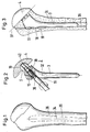
- Fig. 1
- Schematisch einen Humerus mit einem Gelenkkopf;
- Fig. 2
- schematisch eine Schaftprothese mit einem im Humerus einsetzbaren Stiel und einem daran festsetzbaren Kopf;
- Fig. 3
- schematisch eine Schaftprothese von Figur 2,
die in einen Humerus nach
Figur 1 eingesetzt ist; - Fig. 4
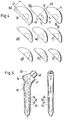
- schematisch eine Seitenansicht von verschieden grossen Prothesenköpfen für eine Humerusprothese nach Figur 2;
- Fig. 5
- schematisch in zwei Ansichten verschieden
grosse Prothesenstiele, die mit Prothesenköpfen
der
Figur 4 kombinierbar sind; - Fig. 6
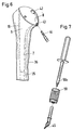
- schematisch eine in einem Humerus eingesetzte Probierprothese;
- Fig. 7
- schematisch ein Ausziehwerkzeug für eine
Probierprothese nach
Figur 6 mit einem daran ansetzbaren Gleithammer; - Fig. 8
- schematisch eine Explosionszeichnung von einer Montagevorrichtung für Humerusprothesen;
- Fig. 9
- schematisch die Montagevorrichtung von
Figur 8 mit einer eingesetzten Probierprothese; - Fig. 10
- schematisch die Montagevorrichtung von
Figur 8 mit einer eingesetzten Schaftprothese und mit einem Drehmomentschlüssel beim Festsetzen des Prothesenkopfes; - Fig. 11
- schematisch eine im Humerus eingesetzte Probierprothese beim Fixieren des Prothesenkopfes in einer bevorzugten Stellung zum Prothesenstiel;
- Fig. 12
- schematisch eine lose in eine
Montagevorrichtung von
Figur 8 eingelegte Probierprothese vor dem Einspannen des Prothesenstiels; - Fig. 13
- schematisch ein Ausrichten der Neigung einer schwimmenden Scheibe zur Unterseite vom Kopf einer am Stiel eingespannten Probierprothese; und
- Fig. 14
- schematisch ein Nachfahren der Anzeige für die
Lage vom Versatz zwischen Mittelachse und
Lagerschalenzentrum am Kopf einer
Probierprothese der
Figur 13.
- Fig. 1
- Schematically a humerus with a condyle;
- Fig. 2
- schematically a stem prosthesis with a stem insertable in the humerus and a head fixable thereon;
- Fig. 3
- schematically a shaft prosthesis of Figure 2, which is inserted into a humerus according to Figure 1;
- Fig. 4
- schematically a side view of different sized prosthesis heads for a humeral prosthesis according to Figure 2;
- Fig. 5
- schematically in two views prosthesis stems of different sizes, which can be combined with the prosthesis heads of FIG. 4;
- Fig. 6
- schematically a trial prosthesis inserted in a humerus;
- Fig. 7
- schematically a pull-out tool for a trial prosthesis according to Figure 6 with a slide hammer attachable to it;
- Fig. 8
- schematically shows an exploded view of an assembly device for humeral prostheses;
- Fig. 9
- schematically the assembly device of Figure 8 with an inserted trial prosthesis;
- Fig. 10
- schematically the assembly device of Figure 8 with an inserted stem prosthesis and with a torque wrench when fixing the prosthesis head;
- Fig. 11
- schematically a trial prosthesis used in the humerus when fixing the prosthesis head in a preferred position to the prosthesis stem;
- Fig. 12
- schematically a trial prosthesis loosely inserted into an assembly device of FIG. 8 before the prosthetic handle is clamped;
- Fig. 13
- schematically aligning the inclination of a floating disc to the bottom of the head of a trial prosthesis clamped on the stem; and
- Fig. 14
- schematically follows the display for the position of the offset between the central axis and the bearing shell center at the head of a trial prosthesis of FIG. 13.
In den Figuren ist ein Baukasten zum Montieren von
Schaftprothesen gezeigt, welche eine in einem
vorbestimmten Winkelbereich festsetzbare Kupplung
zwischen Prothesenstiel 3 und Prothesenkopf 4 aufweisen,
die durch eine Vorrichtung im Prothesenstiel 3
festsetzbar ist. Durch einen Baukasten mit kombinierbaren
verschieden grossen Stielen und Prothesenköpfen für
äusserlich und in der Lage der Drehpunkte baugleiche
Prothesen 3, 4 und Probierprothesen entsteht eine
Vielfalt von Probierprothesen und Schaftprothesen. Die
Probierprothesen besitzen eine Vorrichtung im
Prothesenkopf, die das Festsetzen der Kopfes bei in einen
Knochen eingesetzten Stiel in einer optimalen Stellung
mit kontrollierbarer Funktion erlauben. Diese Stellung
zwischen Kopf und Stiel wird beim Ziehen der
Probierprothese beibehalten und auf eine
Montagevorrichtung übertragen 1, in der eine aus analogen
Teilen aufgebaute Schaftprothese 3, 4 in die gleiche
Stellung gebracht und fixiert wird.In the figures is a kit for assembling
Shaft prostheses shown, which are one in one
predetermined angular range lockable clutch
have between
In den Figuren 1 bis 5 sind Schaftprothesen 2 für einen
Humerus 36 gezeigt, die mit einem Stiel 3 in dem
erweiterten Markkanal 35 des Humerus verankert sind. Der
erweiterte Markkanal ist mit einer Nut 18 versehen, die
eine Finne 19 vom Stiel 3 führt und dem Stiel eine
eindeutige Lage verleiht. Stielachse 32 und Achse 34 vom
Markkanal fallen ungefähr zusammen. Der Prothesenschaft
besteht aus einer warmgeschmiedeten Legierung
beispielsweise nach ISO 5832-9 und besitzt vier Grössen
S1 bis S4 (Figur 5). Der Stiel 3 hat Trompetenform, um ein
gezieltes Verblocken beim Einsetzen zu erreichen.
Rotationsstabilität wird durch die laterale Finne 19 im
proximalen Bereich erreicht. Ein Kugelkopf bildet die
Kupplung 5 zum Prothesenkopf 4. Er bildet mit der
Schaftachse 32 einen Winkel 41 von 130°. Der Kugelkopf
ist durch den Stiel hindurch mit einer Bohrung versehen
und durch Längsschlitze in vier abbiegbare Lappen 48
unterteilt. Ein Aufspreizen der Lappen 48 erfolgt durch
einen Expansionskonus 40 und eine im Stiel verankerte
Expansionsschraube 39, die mit einem Drehmomentschlüssel
38 eingedreht wird, um die Expansionskräfte zu begrenzen.
Der Prothesenkopf 4 besteht aus einer Gusslegierung (ISO
5832-4) und ist in verschiedenen Durchmessern 46 und
Höhen 47 ausgeführt (Grössen a bis i Figur 4). Die
Unterseite 23 des Kopfes bildet eine ebene Auflagefläche.
Jeder Prothesenkopf besitzt die gleiche kugelförmige
Lagerschale 11, die im Längsschnitt mehr als 180°
gekrümmt ist und die einen gleichen Abstand zur
Unterseite 23 vom Kopf aufweist. Zwischen dem Zentrum 12
der Lagerschale 11 und der Mittelachse 13 besteht ein
Versatz 45 mit dem der Prothesenkopf 4 um das Zentrum 12
der Lagerschale 11 gedreht werden kann.Shaft prostheses 2 for a
Damit der Prothesenkopf 4 wie in Figur 3 auf einer
Resektionsfläche 37 aufliegt, diese möglichst genau
abdeckt und eine für seine Funktion passende Höhe 47
aufweist, sind in ihren äusseren Abmessungen baugleiche
Probierprothesen 6 vorgesehen, deren Stiele 7 und Köpfe 8
sich wie bei den eigentlichen Schaftprothesen 2
kombinieren lassen. Es besteht ebenfalls eine Kupplung 9
als festsetzbares Kugelgelenk 10 mit gleicher Lage vom
Zentrum 12 und mit gleichem Versatz 45 zur Mittelachse im
Prothesenkopf 8. Im Unterschied zur Schaftprothese 2 ist
das Lager der Probierprothese 6 mit fünf Madenschrauben,
die durch Bohrungen 43 in der Artikulationsfläche im
eingesetzten Zustand mit einem Werkzeug 44 erreichbar
sind, während dem Einsetzen in eine optimale Stellung
drehbar gehalten und nach dem Erreichen dieser Stellung
lösbar festsetzbar. In Figur 6 ist eine eingesetzte
Probierprothese 6 gezeigt. Am Prothesenkopf 8 sind radial
verlaufende Gewindebohrungen 43 angebracht, in denen
Madenschrauben eingedreht sind, die das Lager im Kopf
festsetzen. Fünf Madenschrauben sind über den Umfang
verteilt, damit wenigstens zwei davon im eingesetzten
Zustand mit dem Werkzeug 44 erreichbar sind. Eine weitere
Bohrung 42 in der Artikulationsfläche ermöglicht den
Zugang zu einem Gewinde für ein Ausziehwerkzeug 49 (Figur
7), an welches ein Gleithammer 50, 50a ansetzbar ist. Bei
genügend grosser Lagerschale 11 der Probierprothese,
lässt sich das Ausziehwerkzeug 49 in ein Gewinde am
Kugelkopf vom Stiel 7 einschrauben, um die Ausziehkräfte
direkt auf den Stiel 7 zu bringen und die Stellung des
festgesetzten Gelenks 9 nicht zu gefährden.So that the
Die Montagevorrichtung 1 in Figur 8 besteht aus einem
Ständer 29 mit Fuss 51. Erste Aufnahmevorrichtungen 14,
15 für Prothesenstiele sind mit einem Schlitten A
verbunden, der an einer Führung 31 längs des Ständers 29
beweglich ist und dessen Gewicht mit einer Feder 52
teilweise kompensiert wird. Der Schlitten A kann in
verschiedenen Höhenlagen mit einer Schraube F blockiert
werden. Hülsen 15, die jeweils eine Aufnahmefläche und
eine Nut 18 für eine bestimmte Stielgrösse und die
dazugehörige Finne 19 besitzen, werden mit einer Schraube
C in einer eindeutigen Lage auf dem Schlitten A, 14
befestigt. An der Hülse 15 greift eine Schraube E ein,
mit der ein eingesetzter Stiel 3, 7 in wiederholbarer
eindeutiger Lage klemmbar ist.The mounting
Eine zweite Aufnahmevorrichtung 16, die über eine
Schraube 54 am Ende des Ständers 29 befestigt ist, trägt
einen aufgeschnittenen Ring 53, dessen Durchmesser über
eine Stellschraube G geringfügig veränderbar ist. In
diesen Ring 53 ist eine schwimmende Scheibe D (punktiert
gezeichnet) eingesetzt, die in ausgezogenen Linien 20
noch einmal ausserhalb dargestellt ist. Die schwimmende
Scheibe D, 20 kann geführt im Ring 53 in eine beliebige
Winkelstellung gedreht werden. Die äussere Lagerfläche 26
der schwimmenden Scheibe 20 entspricht dem Äquatorband
einer Kugelfläche 27, für die eine ringförmige
Gegenfläche 28 im aufgeschnittenen Ring 53 eingearbeitet
ist. Durch Verstellen der Schraube G kann die schwimmende
Scheibe D, 20 in einer beliebigen Winkelstellung
blockiert werden. Die schwimmende Scheibe 20 hat eine
mittlere Öffnung 21, durch welche Prothesenstiele 3, 7
ohne zu Berühren hindurchsteckbar sind. Ausserdem ist auf
der schwimmenden Scheibe eine auf dem Umfang
verschiebbare Drehscheibe I mit Marke H (Figur 14)
angebracht, die mit einer Schraube K in einer
vorgesehenen Winkellage blockiert werden kann. Am Ring 53
sind radial einsteckbare Stifte 55, 56 angebracht, die
die schwimmende Scheibe D als Anschläge in einer
vorgesehenen Standard Stellung, die einer
Durchschnittsstellung von vielen Patienten entspricht,
positionieren können.A
In Figur 9 ist eine Probierprothese mit ihrem Stiel 7 in
der ersten Aufnahmevorrichtung 14 eingespannt und
bestimmt mit ihrem Kopf 8 auf dessen Unterseite, die an
einer Resektionsfläche abgegriffene Winkelstellung,
welche die schwimmende Scheibe D, 20 bei vorsichtigem
Absenken vom Schlitten A einnimmt. In dieser Stellung
wird mit der Schraube 30, K eine Marke H an eine
Markierung am Kopf 8 gedreht, die der Richtung vom
Versatz 45 entspricht, und blockiert, um für die später
in der Montagevorrichtung eingesetzte Schaftprothese 2
die Lage vom Versatz zu speichern.FIG. 9 shows a trial prosthesis with its
In Figur 10 ist die Probierprothese inzwischen nach dem
Lösen der Schraube E entfernt worden. Der Schlitten A
wird zunächst in eine etwas höhere Position gebracht, um
die baugleiche Schaftprothese 2 mit ihrem Stiel 3 in der
ersten Aufnahmevorrichtung 14 zu positionieren und zu
klemmen. Anschliessend wird der Schlitten G vorsichtig
abgesenkt, damit der auf dem Stiel 3 schwenkbare
Prothesenkopf 4 mit seiner Unterseite die Lage der
blockierten schwimmenden Scheibe d.h. die Ebene der
Resektionsfläche einnimmt. In dieser Neigung wird der
Kopf 4 soweit gedreht bis seine Markierung für den
Versatz mit der Marke H d.h. mit dem Versatz der
Probierprothese übereinstimmt. In dieser Stellung wird
die Expansionsschraube 39 mit einem Drehmomentschlüssel
38 angezogen, um das Lager 5, 11 kontrolliert
festzusetzen. Die Schaftprothese 2 entspricht jetzt der
vorher an Ort kontrollierten Probierprothese 6 und kann
implantiert werden.In Figure 10, the trial prosthesis is now after
Loosening the screw E has been removed. The sledge A
is first brought to a slightly higher position
the identical stem prosthesis 2 with its
In den Figuren 11 bis 14 sind die Schritte an der Probierprothese in einer Folge aufgezeigt:
- In
Figur 14 wird derKopf 8 einer passenden Probierprothese, die mit ihremStiel 7 in einer eindeutigenPosition im Markkanal 35 eines Humerus eingesetzt ist, nach der Lage der Resektionsfläche ausgerichtet und relativ zumStiel 7 in dieser Positionmit dem Werkzeug 44 durch Eindrehen von Madenschrauben gesichert.Mit einem Ausziehwerkzeug 49 wird der Schaft durch eine Bohrung 42 gefasst und ausgezogen. Die restlichen Madenschrauben werden ebenfalls angezogen zur besseren Sicherung der Winkelstellung desKopfes 8. - In
Figur 12 ist die Probierprothese lose auf der schwimmenden Scheibe D aufgesetzt worden. Der Schlitten A wird zunächst nach unten gefahren, um eine zumStiel 7 passende Hülse B, 15 in der ersten Aufnahmevorrichtung einzulegen und mit Schraube C zu sichern. Anschliessend wird der Schlitten A nach oben gefahren und derStiel 7 in der Hülse B, 15 positioniert und mit Schraube E gesichert. - In
Figur 13 wird der Schlitten A vorsichtig nach unten gefahren, damit sich die schwimmende Scheibe D nach der Neigung der Unterseite des Kopfes ausrichtet und die Neigung durch Anziehen der Schraube G fixiert. - In
Figur 14 wird in der geneigten Ebene der schwimmenden Scheibe D eine Drehscheibe mit einer Marke H an den Ort verschoben, der aufdem Kopf 8 die Lage vom Versatz anzeigt, und die Drehscheibe I anschliessend mit einer Schraube K gegenüber der schwimmenden Scheibe D gesichert. Der Zustand entspricht jetzt der Darstellung von Figur 9. Die Stellung der Probierprothese ist inder Montagevorrichtung 1 gespeichert und die Probierprothese kann nach dem Lösen der Klemmschraube E entfernt werden.
- In FIG. 14, the
head 8 of a suitable trial prosthesis, which is inserted with itsstem 7 in a clear position in themedullary canal 35 of a humerus, is aligned with the position of the resection surface and relative to thestem 7 in this position with thetool 44 by screwing in grub screws secured. The shaft is gripped and pulled out through abore 42 using a pull-outtool 49. The remaining grub screws are also tightened to better secure the angular position of thehead 8. - In Figure 12, the trial prosthesis has been placed loosely on the floating disc D. The carriage A is first moved downwards in order to insert a sleeve B, 15 which fits the
handle 7 in the first holding device and to secure it with the screw C. The carriage A is then moved upwards and thehandle 7 is positioned in the sleeve B, 15 and secured with the screw E. - In Figure 13, the carriage A is carefully moved downwards so that the floating disc D aligns itself with the inclination of the underside of the head and the inclination is fixed by tightening the screw G.
- In FIG. 14, in the inclined plane of the floating disc D, a turntable with a mark H is moved to the location that indicates the position of the offset on the
head 8, and the turntable I is then secured with a screw K relative to the floating disc D. The state now corresponds to the illustration in FIG. 9. The position of the trial prosthesis is stored in theassembly device 1 and the trial prosthesis can be removed after loosening the clamping screw E.
Claims (11)
Priority Applications (4)
| Application Number | Priority Date | Filing Date | Title |
|---|---|---|---|
| AT98810021T ATE261707T1 (en) | 1998-01-16 | 1998-01-16 | CONSTRUCTION KIT FOR SHAFT PROSTHESES |
| DE59810997T DE59810997D1 (en) | 1998-01-16 | 1998-01-16 | Construction kit for socket prostheses |
| EP98810021A EP0931522B1 (en) | 1998-01-16 | 1998-01-16 | Assembling set for shaft prostheses |
| US09/229,135 US6203575B1 (en) | 1998-01-16 | 1999-01-12 | Modular system for shaft prostheses |
Applications Claiming Priority (1)
| Application Number | Priority Date | Filing Date | Title |
|---|---|---|---|
| EP98810021A EP0931522B1 (en) | 1998-01-16 | 1998-01-16 | Assembling set for shaft prostheses |
Publications (2)
| Publication Number | Publication Date |
|---|---|
| EP0931522A1 true EP0931522A1 (en) | 1999-07-28 |
| EP0931522B1 EP0931522B1 (en) | 2004-03-17 |
Family
ID=8235894
Family Applications (1)
| Application Number | Title | Priority Date | Filing Date |
|---|---|---|---|
| EP98810021A Expired - Lifetime EP0931522B1 (en) | 1998-01-16 | 1998-01-16 | Assembling set for shaft prostheses |
Country Status (4)
| Country | Link |
|---|---|
| US (1) | US6203575B1 (en) |
| EP (1) | EP0931522B1 (en) |
| AT (1) | ATE261707T1 (en) |
| DE (1) | DE59810997D1 (en) |
Cited By (19)
| Publication number | Priority date | Publication date | Assignee | Title |
|---|---|---|---|---|
| JP2002078724A (en) * | 2000-07-28 | 2002-03-19 | Depuy Orthopaedics Inc | Assembly of artificial organs and method for using the same |
| FR2826256A1 (en) * | 2001-06-21 | 2002-12-27 | Depuy France | PROSTHESIS FOR TRAUMATIC SHOULDER |
| FR2832922A1 (en) * | 2001-12-04 | 2003-06-06 | Jean Claude Bouvet | Shoulder joint prosthesis has rectangular medullary nail connected to ball head engaging glenoid cavity |
| US6673114B2 (en) | 2000-05-03 | 2004-01-06 | Smith & Nephew, Inc. | Multi modular trialing system and instrumentation |
| EP1405614A2 (en) * | 2002-09-30 | 2004-04-07 | Depuy Products, Inc. | Shoulder prosthesis |
| WO2004030581A3 (en) * | 2002-10-06 | 2004-07-15 | Martin Bernhard Walder | Endoprosthesis for a shoulder joint |
| US6887277B2 (en) | 2001-11-21 | 2005-05-03 | Centerpulse Orthopedics Ltd. | Shoulder joint prosthesis |
| US6899736B1 (en) | 2002-08-21 | 2005-05-31 | Centerpulse Orthopedics, Ltd. | Shoulder joint prosthesis |
| US6953479B2 (en) | 2001-07-16 | 2005-10-11 | Smith & Nephew, Inc. | Orthopedic implant extension |
| EP1681038A3 (en) * | 2004-12-29 | 2008-01-23 | DePuy Products, Inc. | Replicating orthopaedic implant orientation |
| WO2008117058A1 (en) * | 2007-03-28 | 2008-10-02 | Depuy International Limited | Assembly for use in implantation of a joint component |
| EP1996124A2 (en) * | 2006-03-21 | 2008-12-03 | Axiom Orthopaedics, Inc. | Femoral and humeral stem geometry and implantation method for orthopedic joint reconstruction |
| US8002838B2 (en) | 2008-06-11 | 2011-08-23 | Depuy Products, Inc. | Joint prosthesis with positionable head |
| US8273093B2 (en) | 2004-06-29 | 2012-09-25 | Depuy Products, Inc. | Instrumentation for recording and replicating orthopaedic implant orientation |
| US8419798B2 (en) | 2003-12-30 | 2013-04-16 | Depuy Products, Inc. | Joint prosthesis with infinitely positionable head |
| US8444698B2 (en) | 2004-12-29 | 2013-05-21 | Depuy Products, Inc. | Joint prosthesis with infinitely positionable head |
| EP2685939A2 (en) * | 2011-03-16 | 2014-01-22 | Smith&Nephew, Inc. | Compound angle implant |
| US8679185B2 (en) | 2005-09-30 | 2014-03-25 | DePuy Synthes Products, LLC | Joint prosthesis with positionable head |
| FR3008607A1 (en) * | 2013-07-17 | 2015-01-23 | Tornier Sa | SURGICAL KIT FOR REALIZING ARTHROPLASTY OF THE SHOULDER |
Families Citing this family (54)
| Publication number | Priority date | Publication date | Assignee | Title |
|---|---|---|---|---|
| US20030109475A1 (en) * | 1991-12-17 | 2003-06-12 | The Regents Of The University Of California | Methods and compositions for in vivo gene therapy |
| US5683389A (en) * | 1994-12-05 | 1997-11-04 | Smith & Nephew, Inc. | External fixator for distal radius fractures |
| NO994445D0 (en) * | 1999-09-13 | 1999-09-13 | Bjoern Franc Iversen | A method and a tool for checking the mutual angle between the parts of the hip joint prosthesis |
| US7097663B1 (en) * | 2001-12-17 | 2006-08-29 | Smith & Nephew, Inc. | Modular prosthesis system with novel locking mechanism |
| US7004943B2 (en) * | 2002-02-04 | 2006-02-28 | Smith & Nephew, Inc. | Devices, systems, and methods for placing and positioning fixation elements in external fixation systems |
| US7048735B2 (en) | 2002-02-04 | 2006-05-23 | Smith & Nephew | External fixation system |
| US6746487B2 (en) | 2002-03-06 | 2004-06-08 | Smith & Nephew, Inc. | Intramedullary trial fixation device |
| US7182786B2 (en) | 2002-04-25 | 2007-02-27 | Zimmer Technology, Inc. | Modular bone implant, tool, and method |
| US20030204268A1 (en) * | 2002-04-25 | 2003-10-30 | Medicinelodge, Inc. | Binary attachment mechanism and method for a modular prosthesis |
| WO2003105704A1 (en) | 2002-06-14 | 2003-12-24 | Smith & Nephew, Inc. | Device and methods for placing external fixation elements |
| US6736851B2 (en) * | 2002-06-28 | 2004-05-18 | Depuy Orthopaedics, Inc. | Modular shoulder prosthesis |
| FR2841768B1 (en) * | 2002-07-05 | 2005-05-06 | Tornier Sa | SHOULDER OR HIP PROSTHESIS FACILITATING ABDUCTION |
| DE50205821D1 (en) * | 2002-08-30 | 2006-04-20 | Zimmer Gmbh Winterthur | operation system |
| US6986547B2 (en) * | 2002-09-30 | 2006-01-17 | Lear Corporation | Hybrid vehicle interior component |
| US6887276B2 (en) * | 2002-12-13 | 2005-05-03 | Medicine Lodge, Inc | Modular implant for joint reconstruction and method of use |
| US7608074B2 (en) * | 2003-01-10 | 2009-10-27 | Smith & Nephew, Inc. | External fixation apparatus and method |
| US7452381B2 (en) * | 2003-01-30 | 2008-11-18 | Mayo Foundation For Medical Education And Research | Radial head replacement system |
| US7887544B2 (en) * | 2003-03-10 | 2011-02-15 | Tornier Sas | Ancillary tool for positioning a glenoid implant |
| US7615080B2 (en) | 2003-06-30 | 2009-11-10 | Depuy Products, Inc. | Joint prosthesis having infinitely adjustable head |
| FR2859099B1 (en) * | 2003-08-25 | 2006-01-06 | Tornier Sa | GLENOIDAL COMPONENT OF SHOULDER PROSTHESIS AND TOTAL SHOULDER PROSTHESIS INCORPORATING SUCH COMPONENT |
| US20050049710A1 (en) * | 2003-08-28 | 2005-03-03 | O'driscoll Shawn W. | Prosthesis for partial replacement of an articulating surface on bone |
| FR2863865B1 (en) * | 2003-12-19 | 2006-10-06 | Tornier Sa | SHOULDER OR HIP PROSTHESIS AND METHOD OF MOUNTING |
| GB2429164B (en) * | 2004-03-11 | 2008-12-24 | Acumed Llc | Systems for bone replacement |
| US7678150B2 (en) | 2004-06-15 | 2010-03-16 | Tornier Sas | Total shoulder prosthesis of an inverted type |
| FR2871371B1 (en) | 2004-06-15 | 2007-04-06 | Tornier Sas | GLENOIDAL COMPONENT OF SHOULDER PROSTHESIS, SET OF COMPONENT ELEMENTS OF SUCH COMPONENT AND TOTAL SHOULDER PROSTHESIS INCORPORATING SUCH COMPONENT |
| US8303665B2 (en) | 2004-06-15 | 2012-11-06 | Tornier Sas | Glenoidal component, set of such components and shoulder prosthesis incorporating such a glenoidal component |
| FR2872025B1 (en) | 2004-06-28 | 2006-08-25 | Tornier Sas | PROSTHESIS OF SHOULDER OR HIP |
| US20060084863A1 (en) * | 2004-10-15 | 2006-04-20 | Jacek Kluzik | Positional verification |
| US8535357B2 (en) * | 2004-12-09 | 2013-09-17 | Biomet Sports Medicine, Llc | Continuous phase compositions for ACL repair |
| US20090132045A1 (en) * | 2005-06-03 | 2009-05-21 | Lafosse Laurent | Instrument for use in a joint replacement procedure |
| CA2610672C (en) * | 2005-06-03 | 2013-09-17 | Depuy Ireland Limited | Instrument for use in a joint replacement procedure |
| CA2610799C (en) * | 2005-06-03 | 2014-08-05 | Depuy Ireland Limited | Instrument for use in a joint replacement procedure |
| FR2896404B1 (en) | 2006-01-24 | 2008-02-29 | Tornier Sas | SURGICAL INSTRUMENTATION ASSEMBLY FOR POSTING AN ANKLE PROSTHESIS |
| US9474619B2 (en) * | 2006-03-21 | 2016-10-25 | Tornier, Inc. | Glenoid component with improved fixation stability |
| WO2007109291A2 (en) * | 2006-03-21 | 2007-09-27 | Axiom Orthopaedics, Inc. | Non-spherical articulating surfaces in shoulder and hip prosthesis |
| FR2899790B1 (en) * | 2006-04-13 | 2008-06-13 | Tornier Sas | GLENOIDAL COMPONENT FOR TOTAL SHOULDER PROSTHESIS, SET OF SUCH COMPONENTS, AND TOTAL SHOULDER PROSTHESIS COMPRISING SUCH A COMPONENT |
| FR2900045B1 (en) * | 2006-04-21 | 2009-01-16 | Tornier Sas | PROSTHESIS OF SHOULDER OR HIP |
| US8945138B2 (en) * | 2006-09-29 | 2015-02-03 | DePuy Synthes Products, LLC | Instrument for modular orthopaedic prosthesis |
| FR2906999B1 (en) | 2006-10-13 | 2009-06-05 | Tornier Sas | PROTHETIC SET OF ANKLE |
| FR2911773B1 (en) * | 2007-01-30 | 2009-03-27 | Tornier Sas | METHOD AND ASSEMBLY OF SURGICAL INSTRUMENTATION FOR POSITIONING A TOTAL REVERSE SHOULDER PROSTHESIS, AND CORRESPONDING PROSTHESIS |
| US20090287309A1 (en) | 2007-01-30 | 2009-11-19 | Tornier Sas | Intra-articular joint replacement |
| US20090270993A1 (en) * | 2008-04-28 | 2009-10-29 | Robin Maisonneuve | Orientation feature on eccentric glenosphere |
| US9408652B2 (en) | 2010-04-27 | 2016-08-09 | Tornier Sas | Intra-articular joint replacement and method |
| FR2966343B1 (en) | 2010-10-22 | 2012-12-07 | Tornier Sa | SET OF GLENOIDIAN COMPONENTS OF SHOULDER PROSTHESIS |
| CN102579168B (en) * | 2012-03-20 | 2014-06-25 | 杭州马斯汀医疗器材有限公司 | Universal prosthetic femoral stem extractor |
| GB2507640B (en) | 2012-09-10 | 2015-08-26 | Acumed Llc | Radial head prosthesis with floating articular member |
| US9770272B2 (en) | 2012-12-12 | 2017-09-26 | Wright Medical Technology, Inc. | Orthopedic compression/distraction device |
| US11071635B2 (en) | 2013-03-08 | 2021-07-27 | Mayo Foundation For Medical Education And Research | Shoulder prosthesis with variable inclination humeral head component |
| JP6495190B2 (en) * | 2013-03-08 | 2019-04-03 | メイヨ フォンデーシヨン フォー メディカル エジュケーション アンド リサーチ | Shoulder prosthesis with variable tilting humeral head component |
| US9763792B2 (en) | 2015-10-01 | 2017-09-19 | Acumed Llc | Radial head prosthesis with rotate-to-lock interface |
| DE102016119674A1 (en) * | 2016-10-14 | 2018-04-19 | Silony Medical International AG | Mounting device for hip stem prosthesis |
| US10543001B2 (en) | 2017-09-20 | 2020-01-28 | Depuy Ireland Unlimited Company | Method and instruments for assembling a femoral orthopaedic prosthesis |
| US10537446B2 (en) | 2017-09-20 | 2020-01-21 | Depuy Ireland Unlimited Company | Method and instruments for assembling an orthopaedic prosthesis |
| US10537341B2 (en) * | 2017-09-20 | 2020-01-21 | Depuy Ireland Unlimited Company | Orthopaedic system and method for assembling prosthetic components |
Citations (10)
| Publication number | Priority date | Publication date | Assignee | Title |
|---|---|---|---|---|
| EP0163121A1 (en) * | 1984-05-11 | 1985-12-04 | Waldemar Link (GmbH & Co.) | Arrangement for producing an endoprosthesis anatomically made to measure |
| US4676798A (en) * | 1984-09-12 | 1987-06-30 | Joint Medical Products Corporation | Socket bearing assembly for a constrained ball and socket joint |
| EP0373078A1 (en) * | 1988-12-07 | 1990-06-13 | Fabrique D'implants Et D'instruments Chirurgicaux Societe A Responsabilite Limitee | Femoral head positioning apparatus |
| US5122145A (en) * | 1990-11-09 | 1992-06-16 | Fishbane Bruce M | Measuring device for use in total hip replacement |
| US5129907A (en) * | 1990-12-10 | 1992-07-14 | Zimmer, Inc. | Patellar clamp and reamer with adjustable stop |
| US5312216A (en) * | 1991-06-28 | 1994-05-17 | Hogg John M | Artificial joint prosthesis |
| WO1994015551A1 (en) * | 1993-01-06 | 1994-07-21 | Smith & Nephew Richards, Inc. | Modular humeral component system |
| FR2727857A1 (en) | 1994-12-08 | 1996-06-14 | Cedior | TOTAL SHOULDER PROSTHESIS |
| US5645607A (en) * | 1995-03-02 | 1997-07-08 | Zimmer, Inc. | Hip stem provisional having adjustable neck offsets |
| WO1997025943A1 (en) * | 1996-01-15 | 1997-07-24 | Depuy France | Set of humeral head prostheses |
Family Cites Families (20)
| Publication number | Priority date | Publication date | Assignee | Title |
|---|---|---|---|---|
| GB1373972A (en) * | 1972-03-09 | 1974-11-13 | Mckee G K | Artificial joints for the body |
| US3815590A (en) * | 1973-05-02 | 1974-06-11 | W Deyerle | Off-set trial prosthesis device and method for hip prosthesis surgery |
| US4003095A (en) * | 1976-04-29 | 1977-01-18 | Howmedica, Inc. | Trispherical prosthetic shoulder device |
| US4404692A (en) * | 1981-09-14 | 1983-09-20 | Eftekhar Nas S | Centering system for hip replacement |
| DE3433859A1 (en) * | 1984-09-14 | 1986-03-27 | Waldemar Link (Gmbh & Co), 2000 Hamburg | JOINT DOPROTHESIS AND INSTRUMENT TO OR RECHARGE THE SAME |
| ES2028879T3 (en) * | 1986-10-25 | 1992-07-16 | Gallinaro, Paolo | HIP PROTEST. |
| NL8702626A (en) * | 1987-11-03 | 1989-06-01 | Orthopaedic Tech Bv | METHOD FOR FORMING A GEOMETRY OF AN ENDOPROTHESIS, A FEMUR HEAD PROSTHESIS, AN ACETABULUM PROSTHESIS, A METHOD FOR BOTTING A FEMUR HEAD PROSTHESIS AND AN INSTRUMENT FOR PLACING ACROTHESES |
| US4919679A (en) * | 1989-01-31 | 1990-04-24 | Osteonics Corp. | Femoral stem surgical instrument system |
| US5108452A (en) * | 1989-02-08 | 1992-04-28 | Smith & Nephew Richards Inc. | Modular hip prosthesis |
| US5019108A (en) * | 1990-02-02 | 1991-05-28 | Bertin Kim C | Modular implant |
| US5156626A (en) * | 1990-06-29 | 1992-10-20 | Zimmer, Inc. | Set of provisional prosthesis instrumentation |
| US5342366A (en) * | 1992-02-19 | 1994-08-30 | Biomet, Inc. | Surgical instruments for hip revision |
| US5342363A (en) * | 1992-11-30 | 1994-08-30 | Wright Medical Technology, Inc. | Medical instrument and procedure |
| DE59309665D1 (en) * | 1993-04-07 | 1999-07-29 | Sulzer Orthopaedie Ag | Rasp and a handle part that can be coupled with it to prepare a long bone for the use of a prosthesis |
| US5593451A (en) * | 1994-06-01 | 1997-01-14 | Implex Corp. | Prosthetic device and method of implantation |
| AU2351395A (en) * | 1994-06-30 | 1996-01-25 | Howmedica Inc. | Modular femoral trial hip replacement system |
| US5514136A (en) * | 1994-09-06 | 1996-05-07 | Wright Medical Technology, Inc. | Surgical instrument for driving and rotating a long bone prosthesis |
| US5569263A (en) * | 1995-01-12 | 1996-10-29 | Orthopaedic Innovations, Inc. | Adjustable provisional articulating device |
| US5858020A (en) * | 1995-12-05 | 1999-01-12 | Metagen, Llc | Modular prosthesis |
| US5882295A (en) * | 1998-04-13 | 1999-03-16 | Spectrum Medical Industries, Inc. | Video camera drape |
-
1998
- 1998-01-16 AT AT98810021T patent/ATE261707T1/en not_active IP Right Cessation
- 1998-01-16 EP EP98810021A patent/EP0931522B1/en not_active Expired - Lifetime
- 1998-01-16 DE DE59810997T patent/DE59810997D1/en not_active Expired - Lifetime
-
1999
- 1999-01-12 US US09/229,135 patent/US6203575B1/en not_active Expired - Fee Related
Patent Citations (10)
| Publication number | Priority date | Publication date | Assignee | Title |
|---|---|---|---|---|
| EP0163121A1 (en) * | 1984-05-11 | 1985-12-04 | Waldemar Link (GmbH & Co.) | Arrangement for producing an endoprosthesis anatomically made to measure |
| US4676798A (en) * | 1984-09-12 | 1987-06-30 | Joint Medical Products Corporation | Socket bearing assembly for a constrained ball and socket joint |
| EP0373078A1 (en) * | 1988-12-07 | 1990-06-13 | Fabrique D'implants Et D'instruments Chirurgicaux Societe A Responsabilite Limitee | Femoral head positioning apparatus |
| US5122145A (en) * | 1990-11-09 | 1992-06-16 | Fishbane Bruce M | Measuring device for use in total hip replacement |
| US5129907A (en) * | 1990-12-10 | 1992-07-14 | Zimmer, Inc. | Patellar clamp and reamer with adjustable stop |
| US5312216A (en) * | 1991-06-28 | 1994-05-17 | Hogg John M | Artificial joint prosthesis |
| WO1994015551A1 (en) * | 1993-01-06 | 1994-07-21 | Smith & Nephew Richards, Inc. | Modular humeral component system |
| FR2727857A1 (en) | 1994-12-08 | 1996-06-14 | Cedior | TOTAL SHOULDER PROSTHESIS |
| US5645607A (en) * | 1995-03-02 | 1997-07-08 | Zimmer, Inc. | Hip stem provisional having adjustable neck offsets |
| WO1997025943A1 (en) * | 1996-01-15 | 1997-07-24 | Depuy France | Set of humeral head prostheses |
Cited By (40)
| Publication number | Priority date | Publication date | Assignee | Title |
|---|---|---|---|---|
| US6673114B2 (en) | 2000-05-03 | 2004-01-06 | Smith & Nephew, Inc. | Multi modular trialing system and instrumentation |
| JP2002078724A (en) * | 2000-07-28 | 2002-03-19 | Depuy Orthopaedics Inc | Assembly of artificial organs and method for using the same |
| JP4606661B2 (en) * | 2000-07-28 | 2011-01-05 | デピュイ・オーソピーディックス・インコーポレイテッド | Prosthetic assembly and method of use |
| US7431736B2 (en) | 2000-07-28 | 2008-10-07 | Depuy Products, Inc. | Device and method for positioning an eccentric humeral head of a humerus prosthesis for a shoulder arthroplasty |
| FR2826256A1 (en) * | 2001-06-21 | 2002-12-27 | Depuy France | PROSTHESIS FOR TRAUMATIC SHOULDER |
| EP1269941A1 (en) * | 2001-06-21 | 2003-01-02 | Depuy France | Shoulder prosthesis |
| US6953479B2 (en) | 2001-07-16 | 2005-10-11 | Smith & Nephew, Inc. | Orthopedic implant extension |
| US6887277B2 (en) | 2001-11-21 | 2005-05-03 | Centerpulse Orthopedics Ltd. | Shoulder joint prosthesis |
| FR2832922A1 (en) * | 2001-12-04 | 2003-06-06 | Jean Claude Bouvet | Shoulder joint prosthesis has rectangular medullary nail connected to ball head engaging glenoid cavity |
| US6899736B1 (en) | 2002-08-21 | 2005-05-31 | Centerpulse Orthopedics, Ltd. | Shoulder joint prosthesis |
| EP1405614A3 (en) * | 2002-09-30 | 2005-11-16 | Depuy Products, Inc. | Shoulder prosthesis |
| EP1405614A2 (en) * | 2002-09-30 | 2004-04-07 | Depuy Products, Inc. | Shoulder prosthesis |
| WO2004030581A3 (en) * | 2002-10-06 | 2004-07-15 | Martin Bernhard Walder | Endoprosthesis for a shoulder joint |
| US8419798B2 (en) | 2003-12-30 | 2013-04-16 | Depuy Products, Inc. | Joint prosthesis with infinitely positionable head |
| US8968327B2 (en) | 2004-06-29 | 2015-03-03 | DePuy Synthes Products, LLC | Instrumentation for recording and replicating orthopaedic implant orientation |
| US8808306B2 (en) | 2004-06-29 | 2014-08-19 | DePuy Synthes Products, LLC | Instrumentation for recording and replicating orthopaedic implant orientation |
| US8273093B2 (en) | 2004-06-29 | 2012-09-25 | Depuy Products, Inc. | Instrumentation for recording and replicating orthopaedic implant orientation |
| US8585711B2 (en) | 2004-06-29 | 2013-11-19 | DePuy Synthes Products, LLC | Instrumentation for recording and replicating orthopaedic implant orientation |
| US8444698B2 (en) | 2004-12-29 | 2013-05-21 | Depuy Products, Inc. | Joint prosthesis with infinitely positionable head |
| EP1681038A3 (en) * | 2004-12-29 | 2008-01-23 | DePuy Products, Inc. | Replicating orthopaedic implant orientation |
| US11298233B2 (en) | 2004-12-29 | 2022-04-12 | DePuy Synthes Products, Inc. | Method of implanting joint prosthesis with infinitely positionable head |
| US8460390B2 (en) | 2004-12-29 | 2013-06-11 | Depuy Products, Inc. | System and method for replicating orthopaedic implant orientation |
| US8562686B2 (en) | 2004-12-29 | 2013-10-22 | DePuy Synthes Products, LLC | Joint prosthesis with infinitely positionable head |
| US10828161B2 (en) | 2004-12-29 | 2020-11-10 | DePuy Synthes Products, Inc. | Method of implanting joint prosthesis with infinitely positionable head |
| US9925047B2 (en) | 2004-12-29 | 2018-03-27 | DePuy Synthes Products, Inc. | Method of implanting joint prosthesis with infinitely positionable head |
| US9132012B2 (en) | 2004-12-29 | 2015-09-15 | DePuy Synthes Products, Inc. | Joint prosthesis with infinitely positionable head |
| US9913720B2 (en) | 2005-09-30 | 2018-03-13 | DePuy Synthes Products, Inc. | Joint prosthesis system with positionable head |
| US8679185B2 (en) | 2005-09-30 | 2014-03-25 | DePuy Synthes Products, LLC | Joint prosthesis with positionable head |
| US9681954B2 (en) | 2005-09-30 | 2017-06-20 | DePuy Synthes Products, Inc. | Joint prosthesis system with positionable head |
| EP1996124B1 (en) * | 2006-03-21 | 2019-10-30 | Tornier, Inc. | Femoral and humeral stem components sytem for orthopedic joint reconstruction |
| EP1996124A2 (en) * | 2006-03-21 | 2008-12-03 | Axiom Orthopaedics, Inc. | Femoral and humeral stem geometry and implantation method for orthopedic joint reconstruction |
| US10898336B2 (en) | 2006-03-21 | 2021-01-26 | Tornier, Inc. | Femoral and humeral stem geometry and implantation method for orthopedic joint reconstruction |
| WO2008117058A1 (en) * | 2007-03-28 | 2008-10-02 | Depuy International Limited | Assembly for use in implantation of a joint component |
| US8128705B2 (en) | 2007-03-28 | 2012-03-06 | Depuy International Limited | Assembly for use in implantation of a joint component |
| US8002838B2 (en) | 2008-06-11 | 2011-08-23 | Depuy Products, Inc. | Joint prosthesis with positionable head |
| AU2012229950B2 (en) * | 2011-03-16 | 2016-05-26 | Francis X. MENDOZA | Compound angle implant |
| RU2637626C2 (en) * | 2011-03-16 | 2017-12-05 | Смит Энд Нефью, Инк. | Composite angular implant |
| EP2685939A2 (en) * | 2011-03-16 | 2014-01-22 | Smith&Nephew, Inc. | Compound angle implant |
| EP2685939A4 (en) * | 2011-03-16 | 2014-08-27 | Smith & Nephew Inc | Compound angle implant |
| FR3008607A1 (en) * | 2013-07-17 | 2015-01-23 | Tornier Sa | SURGICAL KIT FOR REALIZING ARTHROPLASTY OF THE SHOULDER |
Also Published As
| Publication number | Publication date |
|---|---|
| ATE261707T1 (en) | 2004-04-15 |
| DE59810997D1 (en) | 2004-04-22 |
| US6203575B1 (en) | 2001-03-20 |
| EP0931522B1 (en) | 2004-03-17 |
Similar Documents
| Publication | Publication Date | Title |
|---|---|---|
| EP0931522B1 (en) | Assembling set for shaft prostheses | |
| EP1393697B1 (en) | Operating system | |
| EP1093777B1 (en) | Shoulder-endoprosthesis | |
| DE69725209T2 (en) | Acetabular trial prosthesis | |
| EP1572038B1 (en) | Intervertebral implant comprising joint parts that are mounted to form a universal joint | |
| EP1463466B1 (en) | Accessory for implanting a hip endoprosthesis | |
| DE69733976T2 (en) | Surgical drill and retractor | |
| DE2838348C2 (en) | Device for forming a bone opening | |
| DE69730509T2 (en) | DEVICE AND METHOD FOR INSERTING AN IMPLANT | |
| DE69927398T2 (en) | FRONT LATERAL PLATE-SHAPED SPINE MOUNTING DEVICE AND ITS TECHNOLOGY | |
| DE60029702T2 (en) | Implant for a spinal head | |
| DE69725052T2 (en) | Connecting pin for multi-part orthopedic implant | |
| EP0327509B1 (en) | Surgical instrument for inserting acetabular cup prostheses | |
| EP0619990B1 (en) | Kit for an artificial joint cup, especially an acetabular cup | |
| DE4320086A1 (en) | Modular shaft for a revision hip prosthesis system | |
| DE2323456A1 (en) | ARTIFICIAL HIP JOINT | |
| CH638093A5 (en) | DEVICE FOR ADAPTING A HIP JOINT PROSTHESIS. | |
| DE19926923A1 (en) | Modular socket for a ball joint prosthesis | |
| DE10250390A1 (en) | Hip joint cup handling involves spreader cone of axi-slots dividing wall sectors expanded radially onto cup inner wall by central expander for handling all cup types. | |
| DE10149385B4 (en) | Surgical instrument for inserting a vertebral body | |
| EP0808617A2 (en) | Saddle prosthesis | |
| DE2936966A1 (en) | EXTENSION SKULL HOLDER | |
| DE3903438C2 (en) | Modular hip joint endoprosthesis | |
| EP2898860B1 (en) | Hip joint endoprosthesis system | |
| EP0931523B1 (en) | System having an artificial joint component and an instrument for handling the artificial joint component |
Legal Events
| Date | Code | Title | Description |
|---|---|---|---|
| PUAI | Public reference made under article 153(3) epc to a published international application that has entered the european phase |
Free format text: ORIGINAL CODE: 0009012 |
|
| AK | Designated contracting states |
Kind code of ref document: A1 Designated state(s): AT BE CH DE FR GB IT LI |
|
| AX | Request for extension of the european patent |
Free format text: AL;LT;LV;MK;RO;SI |
|
| 17P | Request for examination filed |
Effective date: 19991222 |
|
| AKX | Designation fees paid |
Free format text: AT BE CH DE FR GB IT LI |
|
| 17Q | First examination report despatched |
Effective date: 20030225 |
|
| GRAH | Despatch of communication of intention to grant a patent |
Free format text: ORIGINAL CODE: EPIDOS IGRA |
|
| RAP1 | Party data changed (applicant data changed or rights of an application transferred) |
Owner name: CENTERPULSE ORTHOPEDICS LTD. |
|
| GRAS | Grant fee paid |
Free format text: ORIGINAL CODE: EPIDOSNIGR3 |
|
| GRAA | (expected) grant |
Free format text: ORIGINAL CODE: 0009210 |
|
| AK | Designated contracting states |
Kind code of ref document: B1 Designated state(s): AT BE CH DE FR GB IT LI |
|
| REG | Reference to a national code |
Ref country code: GB Ref legal event code: FG4D Free format text: NOT ENGLISH |
|
| REG | Reference to a national code |
Ref country code: CH Ref legal event code: NV Representative=s name: DR. GRAF & PARTNER INTELLECTUAL PROPERTY Ref country code: CH Ref legal event code: EP |
|
| REF | Corresponds to: |
Ref document number: 59810997 Country of ref document: DE Date of ref document: 20040422 Kind code of ref document: P |
|
| GBT | Gb: translation of ep patent filed (gb section 77(6)(a)/1977) |
Effective date: 20040518 |
|
| ET | Fr: translation filed | ||
| PLBE | No opposition filed within time limit |
Free format text: ORIGINAL CODE: 0009261 |
|
| STAA | Information on the status of an ep patent application or granted ep patent |
Free format text: STATUS: NO OPPOSITION FILED WITHIN TIME LIMIT |
|
| 26N | No opposition filed |
Effective date: 20041220 |
|
| REG | Reference to a national code |
Ref country code: GB Ref legal event code: 732E |
|
| REG | Reference to a national code |
Ref country code: CH Ref legal event code: PUE Owner name: ZIMMER GMBH Free format text: CENTERPULSE ORTHOPEDICS LTD.#ALTGASSE 44#6340 BAAR (CH) -TRANSFER TO- ZIMMER GMBH#SULZER ALLEE 8#8404 WINTERTHUR (CH) |
|
| REG | Reference to a national code |
Ref country code: FR Ref legal event code: TP |
|
| PGFP | Annual fee paid to national office [announced via postgrant information from national office to epo] |
Ref country code: AT Payment date: 20090115 Year of fee payment: 12 |
|
| REG | Reference to a national code |
Ref country code: CH Ref legal event code: PFA Owner name: ZIMMER GMBH Free format text: ZIMMER GMBH#SULZER ALLEE 8#8404 WINTERTHUR (CH) -TRANSFER TO- ZIMMER GMBH#SULZER ALLEE 8#8404 WINTERTHUR (CH) |
|
| PG25 | Lapsed in a contracting state [announced via postgrant information from national office to epo] |
Ref country code: AT Free format text: LAPSE BECAUSE OF NON-PAYMENT OF DUE FEES Effective date: 20100116 |
|
| REG | Reference to a national code |
Ref country code: FR Ref legal event code: PLFP Year of fee payment: 19 |
|
| REG | Reference to a national code |
Ref country code: FR Ref legal event code: PLFP Year of fee payment: 20 |
|
| PGFP | Annual fee paid to national office [announced via postgrant information from national office to epo] |
Ref country code: FR Payment date: 20161215 Year of fee payment: 20 Ref country code: BE Payment date: 20161213 Year of fee payment: 20 |
|
| PGFP | Annual fee paid to national office [announced via postgrant information from national office to epo] |
Ref country code: CH Payment date: 20170112 Year of fee payment: 20 Ref country code: DE Payment date: 20170110 Year of fee payment: 20 |
|
| PGFP | Annual fee paid to national office [announced via postgrant information from national office to epo] |
Ref country code: GB Payment date: 20170111 Year of fee payment: 20 |
|
| PGFP | Annual fee paid to national office [announced via postgrant information from national office to epo] |
Ref country code: IT Payment date: 20170123 Year of fee payment: 20 |
|
| REG | Reference to a national code |
Ref country code: DE Ref legal event code: R071 Ref document number: 59810997 Country of ref document: DE |
|
| REG | Reference to a national code |
Ref country code: CH Ref legal event code: PL |
|
| REG | Reference to a national code |
Ref country code: GB Ref legal event code: PE20 Expiry date: 20180115 |
|
| REG | Reference to a national code |
Ref country code: BE Ref legal event code: MK Effective date: 20180116 |
|
| PG25 | Lapsed in a contracting state [announced via postgrant information from national office to epo] |
Ref country code: GB Free format text: LAPSE BECAUSE OF EXPIRATION OF PROTECTION Effective date: 20180115 |