EP0919202A2 - Frameless stereotactic surgical apparatus - Google Patents
Frameless stereotactic surgical apparatus Download PDFInfo
- Publication number
- EP0919202A2 EP0919202A2 EP98309577A EP98309577A EP0919202A2 EP 0919202 A2 EP0919202 A2 EP 0919202A2 EP 98309577 A EP98309577 A EP 98309577A EP 98309577 A EP98309577 A EP 98309577A EP 0919202 A2 EP0919202 A2 EP 0919202A2
- Authority
- EP
- European Patent Office
- Prior art keywords
- joint
- space coordinates
- brake
- imaging device
- arm
- Prior art date
- Legal status (The legal status is an assumption and is not a legal conclusion. Google has not performed a legal analysis and makes no representation as to the accuracy of the status listed.)
- Granted
Links
Images


Classifications
-
- A—HUMAN NECESSITIES
- A61—MEDICAL OR VETERINARY SCIENCE; HYGIENE
- A61B—DIAGNOSIS; SURGERY; IDENTIFICATION
- A61B90/00—Instruments, implements or accessories specially adapted for surgery or diagnosis and not covered by any of the groups A61B1/00 - A61B50/00, e.g. for luxation treatment or for protecting wound edges
- A61B90/10—Instruments, implements or accessories specially adapted for surgery or diagnosis and not covered by any of the groups A61B1/00 - A61B50/00, e.g. for luxation treatment or for protecting wound edges for stereotaxic surgery, e.g. frame-based stereotaxis
- A61B90/11—Instruments, implements or accessories specially adapted for surgery or diagnosis and not covered by any of the groups A61B1/00 - A61B50/00, e.g. for luxation treatment or for protecting wound edges for stereotaxic surgery, e.g. frame-based stereotaxis with guides for needles or instruments, e.g. arcuate slides or ball joints
-
- A—HUMAN NECESSITIES
- A61—MEDICAL OR VETERINARY SCIENCE; HYGIENE
- A61B—DIAGNOSIS; SURGERY; IDENTIFICATION
- A61B34/00—Computer-aided surgery; Manipulators or robots specially adapted for use in surgery
- A61B34/70—Manipulators specially adapted for use in surgery
Definitions
- the present invention relates to frameless stereotactic surgical apparatus, especially in relation to interactive image-guided surgery.
- the invention finds particular application in conjunction with stereotactic surgery performed in CT imaging systems using a frameless mechanical arm to guide minimally invasive surgical tools and will be described with particular reference thereto. It is to be appreciated, however, that the invention is also applicable to robotic and other mechanical arm mechanisms used as frameless guidance assist devices in other imaging systems including ultrasonic and magnetic resonance imaging (MRI) devices.
- MRI magnetic resonance imaging
- U.S. Patent No. 5,142,930 teaches a mechanical arm having a fixed base at a first end and a tool holder on the other end.
- the tool holder is adapted to hold and guide interventional surgical tools.
- the mechanical arm is associated with a computer coupled to a display device displaying one or more images from an image space of a patient's anatomy generated by an imaging device.
- the computer tracks the location of the surgical tool through physical space, performs a transforming rotation of the physical space to the image space, and causes the display device to show the location of the surgical tool within the image space.
- Optical encoders are arranged at each gimbal joint of the mechanical arm in order to detect rotational or angular movement of the arm segments for accurate tracking of the end tip of a tool relative to the position of fiducial implants disposed in or on the patient.
- a frameless stereotactic arm apparatus that does not rely upon the bulky localization frame or the fiducial implants placed on a patient would reduce the setup time spent before surgery.
- U.S. Patent No. 5,078,140 teaches a jointed robotic arm useful in precisely orienting surgical tools and other implements used in conducting stereotactic surgery or other related procedures on human body parts.
- the mechanical arm used in this system includes six rotatable joints and a set of servo motors for moving the arm into predetermined orientations.
- the servo motors include electromagnetic brakes that are activated whenever power is removed from the robotic arm. Further, all of the servo motors incorporate optical incremental encoders that provide position and velocity feedback to the servo system driving the arm into the above-noted predetermined orientations.
- a specialized computer program with control software continuously monitors the angles and positions between all of the joints of the arm in relation to each other and in relation to a base member which is affixed to a metal ring member of a head frame fixed to a patient's head.
- the robotic arm includes a "free" mode which is useful for decoupling the servo motors from active servo control so that the arm may be manually manipulated.
- the mechanical arm must necessarily be connected to a rigid frame apparatus supported by the scanning table and attached to a relatively immovable body part of a patient, usually the head.
- the frame is bulky and often interferes with access to some parts of the patient's anatomy.
- a frameless stereotactic surgical apparatus includes an imaging device generating image information regarding a specimen disposed adjacent the imaging device.
- the frameless surgical apparatus further includes a mechanical arm assembly having a first base portion mounted in a fixed relationship to the imaging device. A second free end of the mechanical arm assembly is adapted to move into varied positions near the specimen on the imaging device. At least one pivot joint is provided between the base portion of the mechanical arm assembly and the second free end thereof for permitting selective relevant movement between the first base portion of the arm assembly and the second free end.
- the apparatus further includes a brake device adapted to selectively lock the first base portion to the second free end is provided. The brake device is responsive to a brake command signal generated by a control circuit associated with the imaging device.
- the frameless stereotactic arm apparatus can be connected from overhead directly to the imaging apparatus for example from overhead, rather than to a patient's head or to a stereotactic head frame, or the like.
- the frameless stereotactic surgical apparatus includes an arm with multiple arm segments which are lockable into fixed locations so that precise orientation and accurate guidance of surgical instruments is possible.
- the lockable arm segments include frictional brakes at each movable joint for locking the arm into any desired conformation against the force of gravity, but which permit movement of the arm in emergency situations in response to application of a force in excess of a predetermined breakaway threshold force.
- a patient table or support 10 includes a patient supporting surface 12 that is mounted for longitudinal movement relative to a base portion 14 .
- the base portion 14 includes a motor for raising and lowering the patient support surface 12 and for moving the patient support surface longitudinally.
- Position encoders are also provided for generating electrical signals indicative of the height and longitudinal position of the patient support.
- the patient support includes a calibration marker 16 disposed at a known, fixed location.
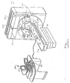
- a planning, preferably volumetric diagnostic imaging apparatus 18 is disposed in axial alignment with the patient table such that a patient or subject on the patient support surface 12 can be moved into and through a bore 20 of the volumetric imager.
- the volumetric imager is a CT scanner which includes an X-ray tube mounted for repeated circular travel within a preselected plane.
- the X-ray tube projects a fan-shaped beam of radiation through a ring 22 of radiation translucent material, through the patient support 12 , through a region of interest of the subject, and to a ring or arc of radiation detectors positioned opposite the X-ray tube.
- the control console is typically remotely located in a shielded room adjacent the scan room containing the imaging apparatus 18 . More specifically to the preferred embodiment, the patient support 12 moves longitudinally as the X-ray tube is rotating around the subject such that a selected volume of the patient is scanned along a spiral path or a series of slices. The position of the X-ray tube is monitored by a rotational position encoder, and the longitudinal position of the patient support is monitored by a longitudinal position encoder within the table 10 . The reconstruction processor reconstructs a volumetric image representation from the generated data lines.
- the control console 24 typically includes one or more monitors 26 and various standard operator input devices, such as a keyboard, trackball, mouse, or the like.
- An interventional control console 28 is supported from overhead on a track atop the CT scanner as shown.
- a mechanical frameless stereotactic arm assembly 30 is supported from overhead by a support arm 32 movable on an oval track system 34 affixed to the top of the volumetric diagnostic imaging apparatus 20 as generally shown.
- the gantry is preferably lockable in one or more predetermined fixed locations on the oval track so that a minimally invasive surgical instrument 36 carried on an interchangeable surgical instrument guidance device 100 in accordance with the present invention can be positioned in monitored positions and orientations by an interventionist in preparation for and in carrying out a surgical procedure.
- the surgical instrument illustrated in the FIGURE includes a biopsy needle 38 carried by a combined laser and cannula guidance device 102 in accordance with a first preferred embodiment of the present invention which will be described below. Overall, however, the position and orientation of the guidance device and the surgical instrument carried thereon are determined by the position of the mechanical arm assembly 30 and the location of the support arm 32 on the oval track system 34 .
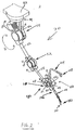
- the frameless stereotactic arm assembly 30 is shown generally in FIGURE 2 and includes a plurality of arm segments which are interconnected by pivot members forming joints between the arm segments. In that way, a free end 40 of the arm is selectively movable in multiple orientations as necessary to position the surgical instrument 36 into various desired positions over the patient support 12 .
- a base member 42 is rigidly connected to the support arm 32 using suitable fasteners, epoxies, or the like.
- a base joint 44 permits rotation of a primary support member 46 in a direction marked A .
- a shoulder joint 48 permits rotation of an upper arm member 50 in a direction marked B
- an elbow joint 52 permits rotation of a lower arm member 54 in a direction marked C
- a forearm joint 56 permits rotation of a knuckle member 58 in a direction marked D
- a wrist joint 60 permits rotation of a wrist member 62 in a direction marked E .
- At least one position resolver and one electromagnetic brake are provided at each joint of the mechanical arm assembly 30 to monitor increment articulation and rotation of the arms relative to each other and to selectively lock the arm in place.
- the optical incremental encoders generate feedback pulses indicative of the movement and relative position of the various arm members in a well known manner.
- the feedback pulses are carried back to an imaging apparatus control circuit using suitable wires or flexible shielded cables extending through the multiple members of the arm assembly. In that way, the position and orientation of the wrist member 62 with respect to the imaging apparatus reference frame and the volumetric image representation are obtained by the imaging apparatus.
- a pair of membrane switches 29, 31 are provided on opposite sides of the wrist member 62 .
- the membrane switches provide a very convenient way for an interventionist to simultaneously unlock the respective mechanical joints of the arm and position the surgical instrument guidance device 100 at various orientations.
- the membrane switches are connected through the mechanical arm to the control circuit illustrated in FIGURE 10.
- One major advantage of placing the membrane switches onto opposite sides of the wrist member is that their location there enables the interventionist to use only one hand for both locking and unlocking the mechanical arm and, further for locating the free end thereof, while the arm is unlocked, into the desired position.
- other suitable toggle buttons, foot switches, or voice recognition systems could equivalently be used.
- the pair of opposing membrane switches are preferred because their position and orientation ensures that the interventionist has a firm grasp of the end of the arm as the brake release in response to the dual actuation of the switches.
- the interventionist must squeeze the switches together to release the brakes.
- the interventionist needs only to use one hand to hold the arm, locate the wrist of the arm in to position and selectively lock and unlock the brakes as necessary.
- the position and orientation of surgical instruments carried by the arm assembly relative to the imaging apparatus reference frame and the volumetric image representation obtained by the imaging apparatus are resolved by providing interchangeable surgical instrument guidance devices 100 having a unique identification signal.
- the identification signal is used by the imaging apparatus control circuit to index a look up table for retrieving various physical dimensional and other functional parameters corresponding to the one or more guidance devices connected to the wrist member 62 .
- the physical dimension and other functional parameters together with the mechanical interconnection which is measured by the resolvers and encoders, provides an accurate indication of the position and orientation of the guidance device 100 relative to the CT scanner and, hence, relative to the image acquired by the CT scanner.
- an instrument coordinate circuit 72 determines the position and trajectory of the surgical instrument 36 in instrument space, particularly a coordinate system of the instrument.
- the instrument coordinate circuit includes a guidance device identification circuit 74 and a mechanical arm assembly position circuit 76 .
- the guidance device identification circuit 74 receives the device identification signal from the one or more guidance devices connected to the mechanical arm and indexes a look up table 78 to retrieve dimensional and functional information.
- the mechanical arm assembly position circuit 76 is connected with the increment resolvers on the mechanical arm assembly 30 to receive signals indicative of changes of position and orientation of the mechanical arm in instrument space.
- An instrument-planning scanner correlating processor 80 determines the correlation or transform between the surgical instrument 36 and the volumetric scanner 18 coordinate systems.
- a calibration instrument is touched to a set of spaced apart markers, preferably eight, which are disposed in a known relationship to the volumetric scanner coordinate system.
- the markers are preferably in the form of a calibration phantom located in the calibration marker area 16 .
- the angular offset is determined.
- the scaling factor is determined.
- an instrument to patient table correlating processor 82 determines the correlation or transform between the patient table and the surgical instrument.
- the calibration phantom described above having the plurality of markers is positioned in a known position on the table to provide a large number of corresponding points in both coordinate systems for the correlating process. Images of the phantom can be utilized to derive transforms between patient table space and planning or real time image coordinate systems.
- Table resolvers 84 located in the patient table contribute vertical and longitudinal offsets to the correlation between the surgical instrument and the patient table when the table is raised or lowered and when the patient support 12 is moved axially.
- An instrument to patient correlation processor 86 determines a correlation between the surgical instrument system and a patient coordinate system. Preferably, this is done by placing the surgical instrument on three or more known references points on the patient. Such points might include readily identifiable anatomical structures such as the tip of the nose, distinctive points of bones, fiducial markers that are aligned during the volumetric imaging process, or the like.
- An instrument to volumetric image coordinate system transform processor 88 receives the correlation or transform from the surgical instrument to planning image processor 80 .
- the instrument to volumetric image processor operates on input position and orientation coordinates in arm space to transform them into volumetric image data space and visa versa. Knowing the position of the surgical instrument in volumetric or planning data space enables the instrument position and orientation to be superimposed on the volumetric planning image data.
- the patient is positioned in the volumetric planning scanner and a volumetric image is generated.
- the volumetric image is stored in a volumetric or planning data memory 90 .
- the position of the patient table during the generation of the planning data, particularly as the table moves to generate spiral or slice data, is stored in conjunction with the volumetric planning data such that the data is correlated with the patient table coordinate system.
- the position of the free end of the arm relative to the patient's body controls the volume planning image data memory or a video processor 92 such that selected slices, projection images, surface renderings, or other conventional displays of the data are generated for display on a planning image display 94 .
- the planning image display includes corresponding sagittal coronal axial and oblique slices through a common point of intersection.
- the planning movement of the surgical instrument is preferably displayed in the planning image.
- the coordinates and trajectory of the surgical instrument are conveyed to the instrument to planning image transform processor 88 for conversion into the planning image coordinate system.
- the location and trajectory of the instrument in the planning image coordinate system is communicated to the video processor 92 which superimposes the surgical instrument position and trajectory on the CT data display.
- the position and orientation of this stereotactic arm assembly 30 is communicated to the interventionist control 28 , which generates cursor position signals and virtual needle displays that are transformed into the planning image coordinate system 94 and communicated to the video processor 92 to generate a movable cursor point and a virtual needle representation on the planning image display 94 .
- the cursor is positioned at the point of intersection of concurrently displayed transverse, coronal, and sagittal views on the volumetric image display 94 .
- the sagittal, coronal, and transverse views automatically change correspondingly.
- FIGURES 4-8 illustrate the brake and encoder assemblies in each of the base, shoulder, elbow, forearm, and wrist joints of the mechanical arm assembly, respectively.
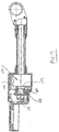
- the base joint 44 is formed generally of a main body section 100 enclosed on one end by a cover assembly 102 .
- the cover assembly is adapted on one end to receive an electrical connector 104 having a plurality of contact pins for communicating various power, logical, and command signals between the mechanical arm assembly and an arm position and brake controller circuit to be subsequently described below.
- the electrical separates the arm position and brake command signals onto a pair of connectors including an 11 pin Fisher connector and a 4 pin Molex connector.
- the cover assembly 102 is adapted to rigidly connect the mechanical arm assembly to the overhead gantry (FIGURE 1).
- the rigid connection between the arm support cover assembly and a bridge mounted on the gantry ensures that cables, wires, or the like extending from the electrical connector will not become twisted or entangled with the mechanical arm as it moves.
- Various types of cable management systems known in the art may be provided for preventing cable twisting and breakage.
- the main body section 100 supports a downwardly extending shaft 106 rotatable on precision bearings 108 .
- a button head socket screw 110 fastens a brake armature 112 and an encoder disk 114 to a free end 116 of the shaft 106 .
- the brake armature and encoder disk move as the shaft rotates with respect to the cover assembly connected to the gantry.
- a brake coil assembly 118 is secured to the cover assembly 102 substantially in a manner as shown.
- an encoder reader 120 is carried on the main body section adjacent an outer end of the encoder disk as shown.
- the encoder disk 114 moves relative to the encoder reader 120 , a series of pulse signals are generated and supplied to the instrument coordinate circuit 72 (FIGURE 3) using suitable electrical connections to the arm position and brake controller circuit.
- the encoder reader is manufactured by immersion and available as Catalog No. 1325.
- the electro-magnetic brake 122 formed of the coil and armature assemblies described above is available from Electroid under Part No. DC86451.
- the commercial brake device is selectively modified by using various forms and type of clutch materials and various forms and types of springs to realize the preferred holding forces at each of the arm joints as set forth below.
- the electro-magnetic brake 122 is adapted to lock the shaft 106 in place when electrical power is removed from the coil assembly 118 .
- the brake armature 112 is released from engagement with the coil assembly to enable relative movement between the shaft 106 and the main body portion 100 connected to the overhead support arm 32 .
- a shoulder joint electromagnetic brake 130 is provided in the shoulder joint 48 between the primary support member 46 and the upper arm member 50 .
- a shaft 132 carries a brake armature 134 and an encoder disk 136 .
- the shaft is connected to the upper arm member 50 using a bolt 138 and is rotatably supported by a shoulder joint base member 140 on precision bearings 142 .
- the brake coil assembly 144 is electrically activated to release and permit free relative movement between the primary support member 46 and the upper arm member 50 .
- An encoder reader 146 is disposed within the base member adjacent the encoder disk 136 in a manner substantially as shown.
- an elbow electromagnetic brake 150 is provided in the elbow joint 52 between the upper arm member 50 and the lower arm member 54 .
- a shaft 152 carries a brake armature 154 and an encoder disk 156 .
- the shaft is connected to the upper arm member 50 using a bolt 158 and is rotatably supported by a shoulder joint base member 160 on precision bearings 162 .
- the brake coil assembly 164 is electrically activated to permit free relative movement between the upper arm member 50 and the lower arm member 54 .
- An encoder reader 166 is disposed within the base member adjacent the encoder disk 156 in a manner substantially as shown.
- a forearm electro-mechanical brake 170 is provided in the forearm joint 56 between the lower arm member 54 and the knuckle member 58 .
- a shaft 172 carries a brake armature 174 and an encoder disk 176 .
- the shaft is connected to the lower arm member 54 using a nut 178 and is rotatably supported by a base member 180 on precision bearings 182 .
- the brake coil assembly (not shown) is electrically activated to release and permit free relative movement between the lower arm member 54 and the wrist member 62 .
- An encoder reader (not shown) is disposed within the base member adjacent the encoder disk in a manner well known in the art.
- a wrist electromechanical brake 190 is provided in the wrist joint 60 between the knuckle member 58 and the wrist member 62 .
- a shaft 192 carries a brake armature 194 and an encoder disk (not shown).
- the shaft is connected to the upper arm member 50 using suitable fasteners and is rotatably supported by a wrist joint base member 200 on precision bearings 202 .
- the brake coil assembly 204 is electrically activated to release and permit free relative movement between the knuckle member 58 and the wrist member 62 .
- An encoder reader (not shown) is disposed within the base member adjacent the encoder disk.
- the brakes described above in the mechanical arm assembly are actuated into a release position by a release command voltage signal 210 generated by a brake controller 212 .
- the brakes are biassed toward a locked or stopped position. In that way, the brakes provide for a fail safe operation of the mechanical arm. Power failures or the like will not cause the arm to release.
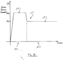
- the release command voltage signal 210 is applied simultaneously to each of the electro-mechanical brakes in a two-step process as shown best in FIGURE 9.
- a brake unlock signal 216 is applied to each of the brake coil assemblies to separate the brake armatures from engagement with the coil assemblies substantially according to manufacturers' specification.
- the brake unlock signal is preferably a 24 volt DC command signal applied to the brake coil assemblies for a period of one (1) second.
- a brake sustain signal 218 is applied to the brake coil assemblies during a second time period 220 for as long as necessary for an interventionist to adjust the arm into a desired position.
- the brake sustain signal 218 is at a reduced voltage level, preferably 17 volts.
- the brake controller 210 receives a pair of arm release signals 222, 224 from the pair of membrane switches 29, 31 disposed on the free end 40 of the mechanical arm assembly 30 substantially as described above.
- the arm release signals are received into an AND circuit 226 which is adapted to generate an arm release initiation signal 228 .
- a processor 230 includes a pair of internal timers for sequentially activating a pair of electronic switches 232, 234 in a manner to connect a first 24 volt voltage source 236 to the brake coil assemblies during the first time period 214 . After the expiration of the first time period as determined by the first timer in the processor 230 , the second switch 234 is electronically closed and the first switch opened thereby connecting the brake coil assemblies with the second 17 volt source 238 .
- a low pass filter 240 is used to condition the brake signal so as to substantially eliminate the noise generated during logical transitions of the signal. Without the low pass filter, the noise generated by the brake signal transitions adversely affect the encoder signals.
- An advantage that flows directly from the low pass filter is the ability to utilize unshielded wires between the brake coil assemblies and the brake controller. This reduces the weight of the mechanical arm assembly and makes it less stiff because smaller wires are more flexible.
Abstract
Description
- The present invention relates to frameless stereotactic surgical apparatus, especially in relation to interactive image-guided surgery. The invention finds particular application in conjunction with stereotactic surgery performed in CT imaging systems using a frameless mechanical arm to guide minimally invasive surgical tools and will be described with particular reference thereto. It is to be appreciated, however, that the invention is also applicable to robotic and other mechanical arm mechanisms used as frameless guidance assist devices in other imaging systems including ultrasonic and magnetic resonance imaging (MRI) devices.
- Heretofore, several mechanical arm type mechanisms have been proposed in interactive imaging systems for guiding interventional surgical tools to allow accurate placement of catheters, drainage tubes, biopsy probes, or the like, within a patient's body. U.S. Patent No. 5,142,930 teaches a mechanical arm having a fixed base at a first end and a tool holder on the other end. The tool holder is adapted to hold and guide interventional surgical tools. The mechanical arm is associated with a computer coupled to a display device displaying one or more images from an image space of a patient's anatomy generated by an imaging device. The computer tracks the location of the surgical tool through physical space, performs a transforming rotation of the physical space to the image space, and causes the display device to show the location of the surgical tool within the image space. Optical encoders are arranged at each gimbal joint of the mechanical arm in order to detect rotational or angular movement of the arm segments for accurate tracking of the end tip of a tool relative to the position of fiducial implants disposed in or on the patient.
- One disadvantage of the above system, however, is the need for a bulky stereotactic localization frame. Although the position of a tool carried on the arm relative to the base is accurately tracked, the use of fiducial implants remains necessary to initialize a mapping between the internal coordinate system of the surgical image and the external coordinate system of the mechanical arm. In addition, the arm described in the system identified above is allegedly easy to manipulate and use because the arm is counterbalanced using conventional weight balancing techniques.
- A frameless stereotactic arm apparatus that does not rely upon the bulky localization frame or the fiducial implants placed on a patient would reduce the setup time spent before surgery.
- U.S. Patent No. 5,078,140 teaches a jointed robotic arm useful in precisely orienting surgical tools and other implements used in conducting stereotactic surgery or other related procedures on human body parts. The mechanical arm used in this system includes six rotatable joints and a set of servo motors for moving the arm into predetermined orientations. The servo motors include electromagnetic brakes that are activated whenever power is removed from the robotic arm. Further, all of the servo motors incorporate optical incremental encoders that provide position and velocity feedback to the servo system driving the arm into the above-noted predetermined orientations. A specialized computer program with control software continuously monitors the angles and positions between all of the joints of the arm in relation to each other and in relation to a base member which is affixed to a metal ring member of a head frame fixed to a patient's head. The robotic arm includes a "free" mode which is useful for decoupling the servo motors from active servo control so that the arm may be manually manipulated.
- One disadvantage, however, of the above stereotactic surgical system is that the mechanical arm must necessarily be connected to a rigid frame apparatus supported by the scanning table and attached to a relatively immovable body part of a patient, usually the head. The frame is bulky and often interferes with access to some parts of the patient's anatomy.
- In accordance with one aspect of the present invention, a frameless stereotactic surgical apparatus is provided. The apparatus includes an imaging device generating image information regarding a specimen disposed adjacent the imaging device. The frameless surgical apparatus further includes a mechanical arm assembly having a first base portion mounted in a fixed relationship to the imaging device. A second free end of the mechanical arm assembly is adapted to move into varied positions near the specimen on the imaging device. At least one pivot joint is provided between the base portion of the mechanical arm assembly and the second free end thereof for permitting selective relevant movement between the first base portion of the arm assembly and the second free end. The apparatus further includes a brake device adapted to selectively lock the first base portion to the second free end is provided. The brake device is responsive to a brake command signal generated by a control circuit associated with the imaging device.
- The frameless stereotactic arm apparatus can be connected from overhead directly to the imaging apparatus for example from overhead, rather than to a patient's head or to a stereotactic head frame, or the like.
- Advantageously, the frameless stereotactic surgical apparatus includes an arm with multiple arm segments which are lockable into fixed locations so that precise orientation and accurate guidance of surgical instruments is possible. Preferably, the lockable arm segments include frictional brakes at each movable joint for locking the arm into any desired conformation against the force of gravity, but which permit movement of the arm in emergency situations in response to application of a force in excess of a predetermined breakaway threshold force.
- Ways of carrying out the invention will now be described in greater detail, by way of example, with reference to the accompanying drawings, in which:
- FIGURE 1 is a diagrammatic illustration of a CT scanner with a frameless stereotactic arm apparatus for guiding surgical instruments in accordance with the present invention;
- FIGURE 2 is a perspective view of the frameless mechanical arm assembly carrying a guidance device in accordance with the present invention;
- FIGURE 3 is a diagrammatic illustration of the planning image processing performed with the apparatus of FIGURE 1;
- FIGURE 4 is a view in cross section of the base joint of the mechanical arm assembly shown in FIGURE 2;
- FIGURE 5 is a view in cross section of the shoulder joint of the mechanical arm assembly shown in FIGURE 2;
- FIGURE 6 is a view in cross section of the elbow joint of the mechanical arm assembly shown in FIGURE 2;
- FIGURE 7 is a view in cross section of the forearm joint of the mechanical arm assembly shown in FIGURE 2;
- FIGURE 8 is a view in cross section of the wrist joint of the mechanical arm assembly shown in FIGURE 2;
- FIGURE 9 is a representative plot of a brake command signal generated by the imaging apparatus shown in FIGURE 1; and
- FIGURE 10 is a schematic illustration of a brake controller used to generate the signal shown in FIGURE 9 for locking the frameless stereotactic arm of FIGURE 2 in predetermined fixed orientations.
-
- Referring now to the drawings, with reference first to FIGURE 1, a patient table or support 10 includes a
patient supporting surface 12 that is mounted for longitudinal movement relative to a base portion 14. The base portion 14 includes a motor for raising and lowering thepatient support surface 12 and for moving the patient support surface longitudinally. Position encoders are also provided for generating electrical signals indicative of the height and longitudinal position of the patient support. The patient support includes acalibration marker 16 disposed at a known, fixed location. - A planning, preferably volumetric
diagnostic imaging apparatus 18 is disposed in axial alignment with the patient table such that a patient or subject on thepatient support surface 12 can be moved into and through a bore 20 of the volumetric imager. In the illustrated embodiment, the volumetric imager is a CT scanner which includes an X-ray tube mounted for repeated circular travel within a preselected plane. The X-ray tube projects a fan-shaped beam of radiation through a ring 22 of radiation translucent material, through thepatient support 12, through a region of interest of the subject, and to a ring or arc of radiation detectors positioned opposite the X-ray tube. As the X-ray tube rotates within the plane, a series of data lines are generated, which data lines are reconstructed into at least a slice image by a reconstruction processor included in a control console 26. The control console is typically remotely located in a shielded room adjacent the scan room containing theimaging apparatus 18. More specifically to the preferred embodiment, thepatient support 12 moves longitudinally as the X-ray tube is rotating around the subject such that a selected volume of the patient is scanned along a spiral path or a series of slices. The position of the X-ray tube is monitored by a rotational position encoder, and the longitudinal position of the patient support is monitored by a longitudinal position encoder within the table 10. The reconstruction processor reconstructs a volumetric image representation from the generated data lines. Thecontrol console 24 typically includes one or more monitors 26 and various standard operator input devices, such as a keyboard, trackball, mouse, or the like. Aninterventional control console 28 is supported from overhead on a track atop the CT scanner as shown. - A mechanical frameless
stereotactic arm assembly 30 is supported from overhead by asupport arm 32 movable on an oval track system 34 affixed to the top of the volumetric diagnostic imaging apparatus 20 as generally shown. The gantry is preferably lockable in one or more predetermined fixed locations on the oval track so that a minimally invasivesurgical instrument 36 carried on an interchangeable surgicalinstrument guidance device 100 in accordance with the present invention can be positioned in monitored positions and orientations by an interventionist in preparation for and in carrying out a surgical procedure. The surgical instrument illustrated in the FIGURE includes a biopsy needle 38 carried by a combined laser andcannula guidance device 102 in accordance with a first preferred embodiment of the present invention which will be described below. Overall, however, the position and orientation of the guidance device and the surgical instrument carried thereon are determined by the position of themechanical arm assembly 30 and the location of thesupport arm 32 on the oval track system 34. - The frameless
stereotactic arm assembly 30 is shown generally in FIGURE 2 and includes a plurality of arm segments which are interconnected by pivot members forming joints between the arm segments. In that way, afree end 40 of the arm is selectively movable in multiple orientations as necessary to position thesurgical instrument 36 into various desired positions over thepatient support 12. Abase member 42 is rigidly connected to thesupport arm 32 using suitable fasteners, epoxies, or the like. Abase joint 44 permits rotation of aprimary support member 46 in a direction marked A. Similarly, from the immovable base end of the arm, ashoulder joint 48 permits rotation of anupper arm member 50 in a direction marked B, anelbow joint 52 permits rotation of alower arm member 54 in a direction marked C, a forearm joint 56 permits rotation of aknuckle member 58 in a direction marked D, and, lastly, awrist joint 60 permits rotation of a wrist member 62 in a direction marked E. - In accordance with the present invention, at least one position resolver and one electromagnetic brake, preferably an optical incremental encoder and friction brake respectively, are provided at each joint of the
mechanical arm assembly 30 to monitor increment articulation and rotation of the arms relative to each other and to selectively lock the arm in place. The optical incremental encoders generate feedback pulses indicative of the movement and relative position of the various arm members in a well known manner. - The feedback pulses are carried back to an imaging apparatus control circuit using suitable wires or flexible shielded cables extending through the multiple members of the arm assembly. In that way, the position and orientation of the wrist member 62 with respect to the imaging apparatus reference frame and the volumetric image representation are obtained by the imaging apparatus.
- Further, in accordance with the present invention, a pair of membrane switches 29, 31 are provided on opposite sides of the wrist member 62. The membrane switches provide a very convenient way for an interventionist to simultaneously unlock the respective mechanical joints of the arm and position the surgical
instrument guidance device 100 at various orientations. The membrane switches are connected through the mechanical arm to the control circuit illustrated in FIGURE 10. One major advantage of placing the membrane switches onto opposite sides of the wrist member is that their location there enables the interventionist to use only one hand for both locking and unlocking the mechanical arm and, further for locating the free end thereof, while the arm is unlocked, into the desired position. As an alternative to the pair of membrane switches, however, other suitable toggle buttons, foot switches, or voice recognition systems could equivalently be used. However, the pair of opposing membrane switches are preferred because their position and orientation ensures that the interventionist has a firm grasp of the end of the arm as the brake release in response to the dual actuation of the switches. The interventionist must squeeze the switches together to release the brakes. Thus, the interventionist needs only to use one hand to hold the arm, locate the wrist of the arm in to position and selectively lock and unlock the brakes as necessary. - The position and orientation of surgical instruments carried by the arm assembly relative to the imaging apparatus reference frame and the volumetric image representation obtained by the imaging apparatus are resolved by providing interchangeable surgical
instrument guidance devices 100 having a unique identification signal. The identification signal is used by the imaging apparatus control circuit to index a look up table for retrieving various physical dimensional and other functional parameters corresponding to the one or more guidance devices connected to the wrist member 62. In this manner, the physical dimension and other functional parameters, together with the mechanical interconnection which is measured by the resolvers and encoders, provides an accurate indication of the position and orientation of theguidance device 100 relative to the CT scanner and, hence, relative to the image acquired by the CT scanner. - With reference now to FIGURE 3, an instrument coordinate
circuit 72 determines the position and trajectory of thesurgical instrument 36 in instrument space, particularly a coordinate system of the instrument. The instrument coordinate circuit includes a guidance device identification circuit 74 and a mechanical arm assembly position circuit 76. The guidance device identification circuit 74 receives the device identification signal from the one or more guidance devices connected to the mechanical arm and indexes a look up table 78 to retrieve dimensional and functional information. The mechanical arm assembly position circuit 76 is connected with the increment resolvers on themechanical arm assembly 30 to receive signals indicative of changes of position and orientation of the mechanical arm in instrument space. An instrument-planning scanner correlating processor 80 determines the correlation or transform between thesurgical instrument 36 and thevolumetric scanner 18 coordinate systems. The correlation or transform is normally described in terms of offset, particularly offset along the axis of the patient support, angular offset or rotation, and scaling. In one embodiment, a calibration instrument is touched to a set of spaced apart markers, preferably eight, which are disposed in a known relationship to the volumetric scanner coordinate system. The markers are preferably in the form of a calibration phantom located in thecalibration marker area 16. By measuring the coordinates of the calibration instrument in the instrument coordinate system while touching each marker, six or more common points in the two coordinate systems are determined. By determining a barrycentre, centroid, or other characteristic point of the common points, the offset between the two coordinate systems is determined. By determining the angular difference between the rays from the barrycentre to each point in each coordinate system, the angular offset is determined. By determining a difference in physical displacement between the barrycentre and the corresponding points in each coordinate system, the scaling factor is determined. Of course, in a system such as the illustrated embodiment in which the instrument and the volumetric scanner are mechanically linked, the transform or relationship between the volumetric scanner and the instrument coordinate system needs only to be calibrated once and, thereafter, is predetermined from the mechanical interconnection between the component parts. The touching of the markers need only be performed once and subsequently used merely to confirm that the instrument and the CT scanner coordinates have not become misaligned between interventional procedures. - Using analogous mathematics or known mechanical relationships as above, an instrument to patient
table correlating processor 82 determines the correlation or transform between the patient table and the surgical instrument. Preferably, the calibration phantom described above having the plurality of markers is positioned in a known position on the table to provide a large number of corresponding points in both coordinate systems for the correlating process. Images of the phantom can be utilized to derive transforms between patient table space and planning or real time image coordinate systems. - Table resolvers 84 located in the patient table contribute vertical and longitudinal offsets to the correlation between the surgical instrument and the patient table when the table is raised or lowered and when the
patient support 12 is moved axially. An instrument topatient correlation processor 86 determines a correlation between the surgical instrument system and a patient coordinate system. Preferably, this is done by placing the surgical instrument on three or more known references points on the patient. Such points might include readily identifiable anatomical structures such as the tip of the nose, distinctive points of bones, fiducial markers that are aligned during the volumetric imaging process, or the like. - An instrument to volumetric image coordinate system transform processor 88 receives the correlation or transform from the surgical instrument to planning image processor 80. The instrument to volumetric image processor operates on input position and orientation coordinates in arm space to transform them into volumetric image data space and visa versa. Knowing the position of the surgical instrument in volumetric or planning data space enables the instrument position and orientation to be superimposed on the volumetric planning image data.
- During a medical procedure, the patient is positioned in the volumetric planning scanner and a volumetric image is generated. The volumetric image is stored in a volumetric or
planning data memory 90. The position of the patient table during the generation of the planning data, particularly as the table moves to generate spiral or slice data, is stored in conjunction with the volumetric planning data such that the data is correlated with the patient table coordinate system. The position of the free end of the arm relative to the patient's body controls the volume planning image data memory or avideo processor 92 such that selected slices, projection images, surface renderings, or other conventional displays of the data are generated for display on a planning image display 94. Preferably, the planning image display includes corresponding sagittal coronal axial and oblique slices through a common point of intersection. - Because the planning image display is generated before the surgical procedure, the planning movement of the surgical instrument is preferably displayed in the planning image. The coordinates and trajectory of the surgical instrument are conveyed to the instrument to planning image transform processor 88 for conversion into the planning image coordinate system. The location and trajectory of the instrument in the planning image coordinate system is communicated to the
video processor 92 which superimposes the surgical instrument position and trajectory on the CT data display. The position and orientation of thisstereotactic arm assembly 30 is communicated to theinterventionist control 28, which generates cursor position signals and virtual needle displays that are transformed into the planning image coordinate system 94 and communicated to thevideo processor 92 to generate a movable cursor point and a virtual needle representation on the planning image display 94. Preferably, the cursor is positioned at the point of intersection of concurrently displayed transverse, coronal, and sagittal views on the volumetric image display 94. As the operator moves the free end of the stereotactic arm assembly through volumetric image data space and as thesurgical instrument 36 on themechanical arm assembly 30 is moved over target areas on the patient, the sagittal, coronal, and transverse views automatically change correspondingly. - FIGURES 4-8 illustrate the brake and encoder assemblies in each of the base, shoulder, elbow, forearm, and wrist joints of the mechanical arm assembly, respectively. With reference now to those FIGURES, but with particular reference first to FIGURE 4, the base joint 44 is formed generally of a
main body section 100 enclosed on one end by acover assembly 102. The cover assembly is adapted on one end to receive anelectrical connector 104 having a plurality of contact pins for communicating various power, logical, and command signals between the mechanical arm assembly and an arm position and brake controller circuit to be subsequently described below. In the preferred embodiment illustrated, the electrical separates the arm position and brake command signals onto a pair of connectors including an 11 pin Fisher connector and a 4 pin Molex connector. - As is evident from viewing the base joint shown in partial cross section, the
cover assembly 102 is adapted to rigidly connect the mechanical arm assembly to the overhead gantry (FIGURE 1). The rigid connection between the arm support cover assembly and a bridge mounted on the gantry ensures that cables, wires, or the like extending from the electrical connector will not become twisted or entangled with the mechanical arm as it moves. Various types of cable management systems known in the art may be provided for preventing cable twisting and breakage. Themain body section 100 supports a downwardly extendingshaft 106 rotatable onprecision bearings 108. A buttonhead socket screw 110 fastens abrake armature 112 and anencoder disk 114 to afree end 116 of theshaft 106. As such, the brake armature and encoder disk move as the shaft rotates with respect to the cover assembly connected to the gantry. Abrake coil assembly 118 is secured to thecover assembly 102 substantially in a manner as shown. Similarly, an encoder reader 120 is carried on the main body section adjacent an outer end of the encoder disk as shown. - Operationally, as the
encoder disk 114 moves relative to the encoder reader 120, a series of pulse signals are generated and supplied to the instrument coordinate circuit 72 (FIGURE 3) using suitable electrical connections to the arm position and brake controller circuit. In the preferred embodiment illustrated, the encoder reader is manufactured by immersion and available as Catalog No. 1325. In addition, the electro-magnetic brake 122 formed of the coil and armature assemblies described above is available from Electroid under Part No. DC86451. However, in accordance with the present invention, the commercial brake device is selectively modified by using various forms and type of clutch materials and various forms and types of springs to realize the preferred holding forces at each of the arm joints as set forth below. - Further in accordance with the preferred embodiment of the invention, the electro-
magnetic brake 122 is adapted to lock theshaft 106 in place when electrical power is removed from thecoil assembly 118. Upon application of electrical power to thebrake coil assembly 118, thebrake armature 112 is released from engagement with the coil assembly to enable relative movement between theshaft 106 and themain body portion 100 connected to theoverhead support arm 32. - Table I below lists the preferred brake and optical encoder types used for each joint of the mechanical arm according to the present invention.
Joint Brake Type Encoder Type Holding Force Base DC86451 3.5", 4096 44.2 in-lb Shoulder DC86456 3.5", 4096 44.2 in-lb Elbow Electroid DC86449 2", 2048 19.5 in-lb Forearm EFSB-3 1", 1024 9 in-lb Wrist Electroid EFSB-1 1", 1024 3 in.-lb. torque - Turning next to FIGURE 5, a shoulder joint
electromagnetic brake 130 is provided in the shoulder joint 48 between theprimary support member 46 and theupper arm member 50. Ashaft 132 carries abrake armature 134 and anencoder disk 136. The shaft is connected to theupper arm member 50 using abolt 138 and is rotatably supported by a shoulderjoint base member 140 onprecision bearings 142. Thebrake coil assembly 144 is electrically activated to release and permit free relative movement between theprimary support member 46 and theupper arm member 50. Anencoder reader 146 is disposed within the base member adjacent theencoder disk 136 in a manner substantially as shown. - Turning next to FIGURE 6, an elbow
electromagnetic brake 150 is provided in the elbow joint 52 between theupper arm member 50 and thelower arm member 54. Ashaft 152 carries abrake armature 154 and anencoder disk 156. The shaft is connected to theupper arm member 50 using abolt 158 and is rotatably supported by a shoulderjoint base member 160 onprecision bearings 162. The brake coil assembly 164 is electrically activated to permit free relative movement between theupper arm member 50 and thelower arm member 54. Anencoder reader 166 is disposed within the base member adjacent theencoder disk 156 in a manner substantially as shown. - Turning next to FIGURE 7, a forearm electro-
mechanical brake 170 is provided in the forearm joint 56 between thelower arm member 54 and theknuckle member 58. Ashaft 172 carries abrake armature 174 and an encoder disk 176. The shaft is connected to thelower arm member 54 using anut 178 and is rotatably supported by abase member 180 onprecision bearings 182. The brake coil assembly (not shown) is electrically activated to release and permit free relative movement between thelower arm member 54 and the wrist member 62. An encoder reader (not shown) is disposed within the base member adjacent the encoder disk in a manner well known in the art. - Turning next to FIGURE 8, a wrist
electromechanical brake 190 is provided in the wrist joint 60 between theknuckle member 58 and the wrist member 62. Ashaft 192 carries a brake armature 194 and an encoder disk (not shown). The shaft is connected to theupper arm member 50 using suitable fasteners and is rotatably supported by a wrist joint base member 200 onprecision bearings 202. Thebrake coil assembly 204 is electrically activated to release and permit free relative movement between theknuckle member 58 and the wrist member 62. An encoder reader (not shown) is disposed within the base member adjacent the encoder disk. - Turning lastly to FIGURES 9 and 10, the brakes described above in the mechanical arm assembly are actuated into a release position by a release
command voltage signal 210 generated by abrake controller 212. In an absence of therelease command signal 210, the brakes are biassed toward a locked or stopped position. In that way, the brakes provide for a fail safe operation of the mechanical arm. Power failures or the like will not cause the arm to release. - In accordance with the preferred embodiment of the instant invention, the release
command voltage signal 210 is applied simultaneously to each of the electro-mechanical brakes in a two-step process as shown best in FIGURE 9. During afirst period 214, abrake unlock signal 216 is applied to each of the brake coil assemblies to separate the brake armatures from engagement with the coil assemblies substantially according to manufacturers' specification. In that regard, the brake unlock signal is preferably a 24 volt DC command signal applied to the brake coil assemblies for a period of one (1) second. - After the first time period, a brake sustain
signal 218 is applied to the brake coil assemblies during asecond time period 220 for as long as necessary for an interventionist to adjust the arm into a desired position. In accordance with the invention, in order to prevent the brake coil assemblies from overheating and, more importantly, from generating large amounts of heat causing the mechanical arm assembly to deviate from its calibration parameters, the brake sustainsignal 218 is at a reduced voltage level, preferably 17 volts. - Turning now more particularly to FIGURE 9, the
brake controller 210 receives a pair of arm release signals 222, 224 from the pair of membrane switches 29, 31 disposed on thefree end 40 of themechanical arm assembly 30 substantially as described above. The arm release signals are received into an AND circuit 226 which is adapted to generate an arm release initiation signal 228. Aprocessor 230 includes a pair of internal timers for sequentially activating a pair ofelectronic switches volt voltage source 236 to the brake coil assemblies during thefirst time period 214. After the expiration of the first time period as determined by the first timer in theprocessor 230, thesecond switch 234 is electronically closed and the first switch opened thereby connecting the brake coil assemblies with the second 17 volt source 238. - Lastly, in connection with the brake controller shown in FIGURE 9, a low pass filter 240 is used to condition the brake signal so as to substantially eliminate the noise generated during logical transitions of the signal. Without the low pass filter, the noise generated by the brake signal transitions adversely affect the encoder signals. An advantage that flows directly from the low pass filter is the ability to utilize unshielded wires between the brake coil assemblies and the brake controller. This reduces the weight of the mechanical arm assembly and makes it less stiff because smaller wires are more flexible.
Claims (9)
- Frameless stereotactic surgical apparatus comprising: an imaging device (18) for generating image information regarding a specimen disposed adjacent the imaging device; a mechanical arm assembly (30) having a base portion (42) mounted in a fixed relationship to the imaging device, a free end (40) adapted to move into varied positions near the specimen, and at least one pivot joint (44, 48, 52, 56, 60) between the base portion and the free end for permitting selective relative movement between the base portion and the free end; and a brake device (122, 136, 146, 156, 166, 176) adapted to selectively lock the base portion to the free end responsive to a brake command signal (210) generated by a control circuit (212) operatively associated with the imaging device.
- Frameless stereotactic surgical apparatus as claimed in claim 1, further comprising a position feedback device (136, 146, 156, 166, 176, 186, 196, 206) generating a joint position signal indicating an orientation of the free end (40) of the mechanical arm assembly relative to the base portion (42).
- Frameless stereotactic surgical apparatus as claimed in claim 2, wherein: the joint position signal is joint position signal information in arm space coordinates relating the mechanical arm assembly to the imaging device; the image information is in scanner space coordinates relating the specimen to the imaging device; and including a transform processor (88) for mapping a position of the free end of the mechanical arm in said arm space coordinates to a position in said scanner space coordinates.
- Frameless stereotactic surgical apparatus as claimed in any one of claims 1 to 3, wherein: said imaging device is adapted to generate said brake command signal at a first level (216) for a first predetermined time period and generate said brake command signal at a second level (218) for a second predetermined time period; said imaging device includes a low pass filter (240) for filtering high frequency noise components from said brake command signal; said brake device (122, 136, 146, 156, 166) is adapted to support said mechanical arm assembly in a predetermined locked position against a force of gravity; and said brake device (122, 136, 146, 156, 166) is adapted to permit movement of said mechanical arm assembly from said predetermined fixed position against a first offsetting force slightly greater than said force of gravity and against a holding force of said brake device.
- Frameless stereotactic surgical apparatus as claimed in any one of claims 1 to 4, wherein said mechanical arm assembly includes: a primary support member (46) connected to said base portion (42) by a base joint (44); an upper arm member (50) connected to said primary support member by a shoulder joint (48); a lower arm member (54) connected to said upper arm member by an elbow joint (52); a knuckle member (58) connected to said lower arm member by a forearm joint (56); and a wrist member (62) at said free end of the mechanical arm assembly and connected to said knuckle member by a wrist joint (60).
- Frameless stereotactic surgical apparatus as claimed in claim 5, further comprising: a base joint electromagnetic brake device (122) at said base joint (44) adapted to selectively lock the base portion (42) to the primary support member (46) responsive to said brake command signal (210); a shoulder joint electro-magnetic brake device (130) at said shoulder joint (48) adapted to selectively lock the primary support member (46) to the upper arm member (50) responsive to said brake command signal (210); an elbow joint electro-magnetic brake device (150) at said elbow joint (52) adapted to selectively lock the upper arm member (50) to the lower arm member (54) responsive to said brake command signal (210); a forearm electro-mechanical brake device (170) at said forearm joint (56) adapted to selectively lock the lower arm member (54) to the knuckle member (58) responsive to said brake command signal (210); and a wrist electro-mechanical brake device (190) at said wrist joint (60) adapted to selectively lock the knuckle member (58) to the wrist member responsive to said brake command signal (210).
- Frameless stereotactic surgical apparatus as claimed in claim 6, wherein: the base joint electro-magnetic brake device has a holding force of approximately 44.2 in-lb; the shoulder joint electro-magnetic brake device has a holding force of approximately 44.2 in-lb; the elbow joint electro-magnetic brake device has a holding force of approximately 19.5 in-lb; the forearm joint electro-mechanical brake device has a holding force of approximately 9 in-lb; and the wrist joint electro-mechanical brake device has a holding force of approximately 3 in-lb.
- A method of using the apparatus of any one of claims 1 to 7, comprising the steps of: using the imaging device (18), generating a image information in scanner space coordinates regarding a patient disposed on the patient support table; generating (76) guide tip position information in guide space coordinates indicating a position of a free end of the guide apparatus relative to a base end of the guide apparatus; transforming (80) the guide tip position information in said guide space coordinates to guide tip position in said scanner space coordinates to relate the guide apparatus to the imaging device; transforming (88) the image information and the guide tip position information in said scanner space coordinates to image space coordinates adapted for display on a human readable display monitor; and displaying (92) on a human readable display monitor (28, 94) said image information in said image space coordinates together with said guide tip position information in said image space coordinates to present a human interventionist with a visual representation of the surgical instrument guide apparatus together with an image of the patient on the patient support table.
- A method of using a surgical instrument guide apparatus (30) with a stereotactic imaging device (18) adapted to receive a patient on a patient support table, the method comprising the steps of: using the imaging device (18), generating image information in scanner space coordinates regarding a patient disposed on the patient support table; generating (76) guide tip position information in guide space coordinates indicating a position of a free end of the guide apparatus relative to a base end of the guide apparatus; transforming (80) the guide tip position information in said guide space coordinates to guide tip position in said scanner space coordinates to relate the guide apparatus to the imaging device; transforming (88) the image information and the guide tip position information in said scanner space coordinates to image space coordinates adapted for display on a human readable display monitor; and displaying (92) on a human readable display monitor (28, 94) said image information in said image space coordinates together with said guide tip position information in said image space coordinates to present a human interventionist with a visual representation of the surgical instrument guide apparatus together with an image of the patient on the patient support table.
Applications Claiming Priority (2)
| Application Number | Priority Date | Filing Date | Title |
|---|---|---|---|
| US08/980,443 US6035228A (en) | 1997-11-28 | 1997-11-28 | Frameless stereotactic arm apparatus and method of using same |
| US980443 | 1997-11-28 |
Publications (3)
| Publication Number | Publication Date |
|---|---|
| EP0919202A2 true EP0919202A2 (en) | 1999-06-02 |
| EP0919202A3 EP0919202A3 (en) | 2000-11-29 |
| EP0919202B1 EP0919202B1 (en) | 2004-09-29 |
Family
ID=25527556
Family Applications (1)
| Application Number | Title | Priority Date | Filing Date |
|---|---|---|---|
| EP98309577A Expired - Lifetime EP0919202B1 (en) | 1997-11-28 | 1998-11-24 | Frameless stereotactic surgical apparatus |
Country Status (4)
| Country | Link |
|---|---|
| US (1) | US6035228A (en) |
| EP (1) | EP0919202B1 (en) |
| JP (1) | JP4277964B2 (en) |
| DE (1) | DE69826611T2 (en) |
Cited By (4)
| Publication number | Priority date | Publication date | Assignee | Title |
|---|---|---|---|---|
| US6482182B1 (en) | 1998-09-03 | 2002-11-19 | Surgical Navigation Technologies, Inc. | Anchoring system for a brain lead |
| US6491699B1 (en) | 1999-04-20 | 2002-12-10 | Surgical Navigation Technologies, Inc. | Instrument guidance method and system for image guided surgery |
| US6491702B2 (en) | 1992-04-21 | 2002-12-10 | Sofamor Danek Holdings, Inc. | Apparatus and method for photogrammetric surgical localization |
| CN113288074A (en) * | 2021-05-17 | 2021-08-24 | 上海交通大学 | Multi-degree-of-freedom position-adjustable pulse-taking mechanical arm device |
Families Citing this family (54)
| Publication number | Priority date | Publication date | Assignee | Title |
|---|---|---|---|---|
| US6149592A (en) * | 1997-11-26 | 2000-11-21 | Picker International, Inc. | Integrated fluoroscopic projection image data, volumetric image data, and surgical device position data |
| JP2002538874A (en) * | 1999-03-17 | 2002-11-19 | コーニンクレッカ フィリップス エレクトロニクス エヌ ヴィ | Computed tomography apparatus having position measurement system |
| US7085400B1 (en) | 2000-06-14 | 2006-08-01 | Surgical Navigation Technologies, Inc. | System and method for image based sensor calibration |
| DE10032203A1 (en) * | 2000-07-01 | 2002-01-17 | Deutsches Krebsforsch | stereotactic |
| CA2443819C (en) * | 2001-05-04 | 2011-07-19 | Board Of Regents, The University Of Texas System | Apparatus and methods for delivery of transcranial magnetic stimulation |
| JP3579379B2 (en) * | 2001-08-10 | 2004-10-20 | 株式会社東芝 | Medical manipulator system |
| US7383073B1 (en) * | 2001-10-16 | 2008-06-03 | Z-Kat Inc. | Digital minimally invasive surgery system |
| US20030208189A1 (en) * | 2001-10-19 | 2003-11-06 | Payman Gholam A. | Integrated system for correction of vision of the human eye |
| JP2005524442A (en) * | 2002-05-02 | 2005-08-18 | ジーエムピー サージカル ソリューションズ インコーポレイテッド | Device for positioning medical instruments |
| AU2003257309A1 (en) * | 2002-08-13 | 2004-02-25 | Microbotics Corporation | Microsurgical robot system |
| DE20218693U1 (en) * | 2002-12-03 | 2003-02-13 | Leica Microsystems Schweiz Ag | Tripod for a surgical microscope |
| US7869859B2 (en) * | 2003-03-10 | 2011-01-11 | Kabushiki Kaisha Toshiba | X-ray CT apparatus having a display to display information inputted from a remote operator console |
| DE10322140B4 (en) * | 2003-05-16 | 2008-07-10 | Siemens Ag | Medical imaging examination device |
| US9259195B2 (en) * | 2003-06-18 | 2016-02-16 | Koninklijke Philips N.V. | Remotely held needle guide for CT fluoroscopy |
| GB0322115D0 (en) | 2003-09-22 | 2003-10-22 | Renishaw Plc | Method of error compensation |
| US7349730B2 (en) * | 2005-01-11 | 2008-03-25 | Moshe Ein-Gal | Radiation modulator positioner |
| US20090318935A1 (en) * | 2005-11-10 | 2009-12-24 | Satish Sundar | Percutaneous medical devices and methods |
| US7757028B2 (en) * | 2005-12-22 | 2010-07-13 | Intuitive Surgical Operations, Inc. | Multi-priority messaging |
| US7756036B2 (en) * | 2005-12-22 | 2010-07-13 | Intuitive Surgical Operations, Inc. | Synchronous data communication |
| US8054752B2 (en) * | 2005-12-22 | 2011-11-08 | Intuitive Surgical Operations, Inc. | Synchronous data communication |
| JP4717683B2 (en) * | 2006-03-30 | 2011-07-06 | 株式会社日立メディコ | Medical image display device |
| US8401620B2 (en) | 2006-10-16 | 2013-03-19 | Perfint Healthcare Private Limited | Needle positioning apparatus and method |
| US8758263B1 (en) * | 2009-10-31 | 2014-06-24 | Voxel Rad, Ltd. | Systems and methods for frameless image-guided biopsy and therapeutic intervention |
| US20120190970A1 (en) | 2010-11-10 | 2012-07-26 | Gnanasekar Velusamy | Apparatus and method for stabilizing a needle |
| KR101802464B1 (en) * | 2011-08-03 | 2017-11-28 | 주식회사 미래컴퍼니 | Master arm structure of surgical robot and control method of surgical master robot |
| US9265965B2 (en) | 2011-09-30 | 2016-02-23 | Board Of Regents, The University Of Texas System | Apparatus and method for delivery of transcranial magnetic stimulation using biological feedback to a robotic arm |
| FR2980683B1 (en) * | 2011-09-30 | 2014-11-21 | Univ Paris Curie | DEVICE FOR GUIDING A MEDICAL INSTRUMENT INSERTED IN A NATURAL PATH OR AN ARTIFICIAL PATH OF A PATIENT |
| US20140081659A1 (en) | 2012-09-17 | 2014-03-20 | Depuy Orthopaedics, Inc. | Systems and methods for surgical and interventional planning, support, post-operative follow-up, and functional recovery tracking |
| USD739526S1 (en) | 2012-12-14 | 2015-09-22 | Conmed Corporation | Connector |
| USD749211S1 (en) | 2012-12-14 | 2016-02-09 | Conmed Corporation | Keyway portion |
| USD739527S1 (en) | 2012-12-14 | 2015-09-22 | Conmed Corporation | Connector |
| DE102013005999A1 (en) * | 2013-04-09 | 2014-10-09 | Carl Zeiss Microscopy Gmbh | Swivel arm stand for digital microscopes |
| US10537277B2 (en) | 2013-05-28 | 2020-01-21 | The Trustees Of The University Of Pennsylvania | Methods, systems, and computer readable media for visualization of resection target during epilepsy surgery and for real time spatiotemporal visualization of neurophysiologic biomarkers |
| CA2918879A1 (en) | 2013-07-24 | 2015-01-29 | Centre For Surgical Invention & Innovation | Multi-function mounting interface for an image-guided robotic system and quick release interventional toolset |
| DE102013226342B4 (en) * | 2013-12-18 | 2022-10-13 | Siemens Healthcare Gmbh | medical equipment |
| KR102457538B1 (en) | 2014-03-17 | 2022-10-24 | 인튜어티브 서지컬 오퍼레이션즈 인코포레이티드 | System and method for breakaway clutching in an articulated arm |
| CN110448345B (en) | 2014-08-12 | 2022-10-14 | 直观外科手术操作公司 | Detecting uncontrolled movement |
| EP3912610B1 (en) | 2014-10-27 | 2023-03-15 | Intuitive Surgical Operations, Inc. | System for registering to a surgical table |
| KR20230129615A (en) | 2014-10-27 | 2023-09-08 | 인튜어티브 서지컬 오퍼레이션즈 인코포레이티드 | System and method for instrument disturbance compensation |
| JP6676061B2 (en) * | 2014-10-27 | 2020-04-08 | インテュイティブ サージカル オペレーションズ, インコーポレイテッド | System and method for integrated operating table motion |
| EP3212149A4 (en) | 2014-10-27 | 2018-05-30 | Intuitive Surgical Operations, Inc. | System and method for integrated surgical table |
| US10682190B2 (en) | 2014-10-27 | 2020-06-16 | Intuitive Surgical Operations, Inc. | System and method for monitoring control points during reactive motion |
| KR102480765B1 (en) | 2014-10-27 | 2022-12-23 | 인튜어티브 서지컬 오퍼레이션즈 인코포레이티드 | Medical device with active brake release control |
| GB2552386B (en) | 2016-07-22 | 2022-06-08 | Cmr Surgical Ltd | Magnetic position sensor mounting arrangement |
| USD998156S1 (en) | 2017-04-21 | 2023-09-05 | Mizuho Orthopedic Systems, Inc. | Surgical drape |
| US10905614B2 (en) | 2017-04-21 | 2021-02-02 | Mizuho Osi | System, apparatus and method for patient positioning prior to, during and/or after medical procedures |
| US11129765B2 (en) * | 2017-04-21 | 2021-09-28 | Mizuho Osi | System, apparatus and method for patient positioning prior to, during and/or after medical procedures |
| CN109470939B (en) * | 2017-09-07 | 2021-01-29 | 深圳市中兴微电子技术有限公司 | Line loss point inspection system and method |
| JP7046599B2 (en) * | 2017-12-28 | 2022-04-04 | キヤノンメディカルシステムズ株式会社 | Medical diagnostic imaging equipment, peripherals and imaging systems |
| GB2572337B (en) * | 2018-03-26 | 2020-10-14 | Elekta ltd | Radiotherapy control system |
| CN109108472A (en) * | 2018-08-30 | 2019-01-01 | 江苏新光数控技术有限公司 | A kind of manipulator for marking machine |
| US10806339B2 (en) | 2018-12-12 | 2020-10-20 | Voxel Rad, Ltd. | Systems and methods for treating cancer using brachytherapy |
| JP7294856B2 (en) * | 2019-04-08 | 2023-06-20 | 川崎重工業株式会社 | robot equipment |
| CN113017666A (en) * | 2021-02-05 | 2021-06-25 | 明峰医疗系统股份有限公司 | Anti-falling brake circuit of diagnostic bed and CT scanning bed |
Citations (2)
| Publication number | Priority date | Publication date | Assignee | Title |
|---|---|---|---|---|
| US5078140A (en) | 1986-05-08 | 1992-01-07 | Kwoh Yik S | Imaging device - aided robotic stereotaxis system |
| US5142930A (en) | 1987-11-10 | 1992-09-01 | Allen George S | Interactive image-guided surgical system |
Family Cites Families (18)
| Publication number | Priority date | Publication date | Assignee | Title |
|---|---|---|---|---|
| US4791934A (en) * | 1986-08-07 | 1988-12-20 | Picker International, Inc. | Computer tomography assisted stereotactic surgery system and method |
| US5099846A (en) * | 1988-12-23 | 1992-03-31 | Hardy Tyrone L | Method and apparatus for video presentation from a variety of scanner imaging sources |
| FR2652928B1 (en) * | 1989-10-05 | 1994-07-29 | Diadix Sa | INTERACTIVE LOCAL INTERVENTION SYSTEM WITHIN A AREA OF A NON-HOMOGENEOUS STRUCTURE. |
| JPH0489000A (en) * | 1990-05-02 | 1992-03-23 | W R Grace & Co | Cell cultivation kit and cell damage testing method |
| US5417210A (en) * | 1992-05-27 | 1995-05-23 | International Business Machines Corporation | System and method for augmentation of endoscopic surgery |
| DE4202302C2 (en) * | 1992-01-28 | 1999-06-10 | Dietrich H W Prof Groenemeyer | Computer tomograph |
| US5657429A (en) * | 1992-08-10 | 1997-08-12 | Computer Motion, Inc. | Automated endoscope system optimal positioning |
| US5524180A (en) * | 1992-08-10 | 1996-06-04 | Computer Motion, Inc. | Automated endoscope system for optimal positioning |
| US5309913A (en) * | 1992-11-30 | 1994-05-10 | The Cleveland Clinic Foundation | Frameless stereotaxy system |
| US5427097A (en) * | 1992-12-10 | 1995-06-27 | Accuray, Inc. | Apparatus for and method of carrying out stereotaxic radiosurgery and radiotherapy |
| DE4304570A1 (en) * | 1993-02-16 | 1994-08-18 | Mdc Med Diagnostic Computing | Device and method for preparing and supporting surgical procedures |
| JPH08509144A (en) * | 1993-04-22 | 1996-10-01 | ピクシス,インコーポレイテッド | System to locate relative position of objects |
| US5590655A (en) * | 1993-09-20 | 1997-01-07 | Hussman; Karl L. | Frameless laser guided stereotactic localization system |
| IL107523A (en) * | 1993-11-07 | 2000-01-31 | Ultraguide Ltd | Articulated needle guide for ultrasound imaging and method of using same |
| US5598269A (en) * | 1994-05-12 | 1997-01-28 | Children's Hospital Medical Center | Laser guided alignment apparatus for medical procedures |
| US5628327A (en) * | 1994-12-15 | 1997-05-13 | Imarx Pharmaceutical Corp. | Apparatus for performing biopsies and the like |
| US5807377A (en) * | 1996-05-20 | 1998-09-15 | Intuitive Surgical, Inc. | Force-reflecting surgical instrument and positioning mechanism for performing minimally invasive surgery with enhanced dexterity and sensitivity |
| US5824007A (en) * | 1996-12-03 | 1998-10-20 | Simon Fraser University | Adjustable surgical stand |
-
1997
- 1997-11-28 US US08/980,443 patent/US6035228A/en not_active Expired - Lifetime
-
1998
- 1998-11-24 DE DE69826611T patent/DE69826611T2/en not_active Expired - Lifetime
- 1998-11-24 EP EP98309577A patent/EP0919202B1/en not_active Expired - Lifetime
- 1998-11-30 JP JP34036998A patent/JP4277964B2/en not_active Expired - Fee Related
Patent Citations (2)
| Publication number | Priority date | Publication date | Assignee | Title |
|---|---|---|---|---|
| US5078140A (en) | 1986-05-08 | 1992-01-07 | Kwoh Yik S | Imaging device - aided robotic stereotaxis system |
| US5142930A (en) | 1987-11-10 | 1992-09-01 | Allen George S | Interactive image-guided surgical system |
Cited By (5)
| Publication number | Priority date | Publication date | Assignee | Title |
|---|---|---|---|---|
| US6491702B2 (en) | 1992-04-21 | 2002-12-10 | Sofamor Danek Holdings, Inc. | Apparatus and method for photogrammetric surgical localization |
| US6482182B1 (en) | 1998-09-03 | 2002-11-19 | Surgical Navigation Technologies, Inc. | Anchoring system for a brain lead |
| US6491699B1 (en) | 1999-04-20 | 2002-12-10 | Surgical Navigation Technologies, Inc. | Instrument guidance method and system for image guided surgery |
| CN113288074A (en) * | 2021-05-17 | 2021-08-24 | 上海交通大学 | Multi-degree-of-freedom position-adjustable pulse-taking mechanical arm device |
| CN113288074B (en) * | 2021-05-17 | 2022-03-15 | 上海交通大学 | Multi-degree-of-freedom position-adjustable pulse-taking mechanical arm device |
Also Published As
| Publication number | Publication date |
|---|---|
| DE69826611D1 (en) | 2004-11-04 |
| JP4277964B2 (en) | 2009-06-10 |
| EP0919202B1 (en) | 2004-09-29 |
| EP0919202A3 (en) | 2000-11-29 |
| US6035228A (en) | 2000-03-07 |
| JPH11253456A (en) | 1999-09-21 |
| DE69826611T2 (en) | 2005-11-17 |
Similar Documents
| Publication | Publication Date | Title |
|---|---|---|
| EP0919202B1 (en) | Frameless stereotactic surgical apparatus | |
| EP0919203B1 (en) | Frameless stereotactic surgical apparatus | |
| US5957933A (en) | Interchangeable guidance devices for C.T. assisted surgery and method of using same | |
| Hempel et al. | An MRI-compatible surgical robot for precise radiological interventions | |
| Loser et al. | A new robotic system for visually controlled percutaneous interventions under CT fluoroscopy | |
| Galloway et al. | Interactive image-guided neurosurgery | |
| Zamorano et al. | Interactive intraoperative localization using an infrared-based system | |
| EP0922438B1 (en) | Image guided interventional procedures | |
| Masamune et al. | Development of an MRI-compatible needle insertion manipulator for stereotactic neurosurgery | |
| EP0427358B1 (en) | Mechanical arm for and interactive image-guided surgical system | |
| US7302288B1 (en) | Tool position indicator | |
| US8041459B2 (en) | Methods relating to microsurgical robot system | |
| EP0895461B1 (en) | Apparatus for surgical stereotactic procedures | |
| EP0995406A1 (en) | Method and apparatus for planning surgical procedures | |
| EP3320874A1 (en) | Systems and methods of checking registration for surgical systems | |
| EP2561821A1 (en) | Tool positioning system | |
| WO2020135784A1 (en) | Medical robot | |
| Jun et al. | MR safe robot assisted needle access of the brain: preclinical study | |
| JP7029932B2 (en) | Systems and methods for measuring the depth of instruments | |
| Hefti et al. | Robotic three‐dimensional positioning of a stimulation electrode in the brain | |
| Benabid et al. | Is there any future for robots in neurosurgery? | |
| Christoforou et al. | Design and testing of a robotic system for MR image-guided interventions | |
| Christoforou et al. | Manipulator for magnetic resonance imaging guided interventions: Design, prototype and feasibility | |
| Newman et al. | External referencing systems | |
| Kadi et al. | Design and simulation of an articulated surgical arm for guiding stereotactic neurosurgery |
Legal Events
| Date | Code | Title | Description |
|---|---|---|---|
| PUAI | Public reference made under article 153(3) epc to a published international application that has entered the european phase |
Free format text: ORIGINAL CODE: 0009012 |
|
| AK | Designated contracting states |
Kind code of ref document: A2 Designated state(s): DE FR NL |
|
| AX | Request for extension of the european patent |
Free format text: AL;LT;LV;MK;RO;SI |
|
| PUAL | Search report despatched |
Free format text: ORIGINAL CODE: 0009013 |
|
| AK | Designated contracting states |
Kind code of ref document: A3 Designated state(s): AT BE CH CY DE DK ES FI FR GB GR IE IT LI LU MC NL PT SE |
|
| AX | Request for extension of the european patent |
Free format text: AL;LT;LV;MK;RO;SI |
|
| RAP1 | Party data changed (applicant data changed or rights of an application transferred) |
Owner name: MARCONI MEDICAL SYSTEMS, INC. |
|
| 17P | Request for examination filed |
Effective date: 20010518 |
|
| AKX | Designation fees paid |
Free format text: DE FR NL |
|
| 17Q | First examination report despatched |
Effective date: 20030304 |
|
| RAP1 | Party data changed (applicant data changed or rights of an application transferred) |
Owner name: PHILIPS MEDICAL SYSTEMS (CLEVELAND), INC. |
|
| RAP1 | Party data changed (applicant data changed or rights of an application transferred) |
Owner name: KONINKLIJKE PHILIPS ELECTRONICS N.V. |
|
| GRAP | Despatch of communication of intention to grant a patent |
Free format text: ORIGINAL CODE: EPIDOSNIGR1 |
|
| GRAS | Grant fee paid |
Free format text: ORIGINAL CODE: EPIDOSNIGR3 |
|
| GRAA | (expected) grant |
Free format text: ORIGINAL CODE: 0009210 |
|
| AK | Designated contracting states |
Kind code of ref document: B1 Designated state(s): DE FR NL |
|
| PG25 | Lapsed in a contracting state [announced via postgrant information from national office to epo] |
Ref country code: NL Free format text: LAPSE BECAUSE OF FAILURE TO SUBMIT A TRANSLATION OF THE DESCRIPTION OR TO PAY THE FEE WITHIN THE PRESCRIBED TIME-LIMIT Effective date: 20040929 |
|
| REF | Corresponds to: |
Ref document number: 69826611 Country of ref document: DE Date of ref document: 20041104 Kind code of ref document: P |
|
| NLV1 | Nl: lapsed or annulled due to failure to fulfill the requirements of art. 29p and 29m of the patents act | ||
| PLBE | No opposition filed within time limit |
Free format text: ORIGINAL CODE: 0009261 |
|
| STAA | Information on the status of an ep patent application or granted ep patent |
Free format text: STATUS: NO OPPOSITION FILED WITHIN TIME LIMIT |
|
| ET | Fr: translation filed | ||
| 26N | No opposition filed |
Effective date: 20050630 |
|
| REG | Reference to a national code |
Ref country code: FR Ref legal event code: D6 |
|
| REG | Reference to a national code |
Ref country code: DE Ref legal event code: R082 Ref document number: 69826611 Country of ref document: DE Representative=s name: MEYER, MICHAEL, DIPL.-ING., DE |
|
| REG | Reference to a national code |
Ref country code: DE Ref legal event code: R082 Ref document number: 69826611 Country of ref document: DE Effective date: 20140331 Ref country code: DE Ref legal event code: R082 Ref document number: 69826611 Country of ref document: DE Representative=s name: MEYER, MICHAEL, DIPL.-ING., DE Effective date: 20140331 Ref country code: DE Ref legal event code: R081 Ref document number: 69826611 Country of ref document: DE Owner name: KONINKLIJKE PHILIPS N.V., NL Free format text: FORMER OWNER: KONINKLIJKE PHILIPS ELECTRONICS N.V., EINDHOVEN, NL Effective date: 20140331 |
|
| REG | Reference to a national code |
Ref country code: FR Ref legal event code: CD Owner name: KONINKLIJKE PHILIPS N.V., NL Effective date: 20141126 Ref country code: FR Ref legal event code: CA Effective date: 20141126 |
|
| REG | Reference to a national code |
Ref country code: FR Ref legal event code: PLFP Year of fee payment: 18 |
|
| PGFP | Annual fee paid to national office [announced via postgrant information from national office to epo] |
Ref country code: DE Payment date: 20160129 Year of fee payment: 18 |
|
| REG | Reference to a national code |
Ref country code: FR Ref legal event code: PLFP Year of fee payment: 19 |
|
| PGFP | Annual fee paid to national office [announced via postgrant information from national office to epo] |
Ref country code: FR Payment date: 20161129 Year of fee payment: 19 |
|
| REG | Reference to a national code |
Ref country code: DE Ref legal event code: R082 Ref document number: 69826611 Country of ref document: DE |
|
| REG | Reference to a national code |
Ref country code: DE Ref legal event code: R119 Ref document number: 69826611 Country of ref document: DE |
|
| PG25 | Lapsed in a contracting state [announced via postgrant information from national office to epo] |
Ref country code: DE Free format text: LAPSE BECAUSE OF NON-PAYMENT OF DUE FEES Effective date: 20170601 |
|
| REG | Reference to a national code |
Ref country code: FR Ref legal event code: ST Effective date: 20180731 |
|
| PG25 | Lapsed in a contracting state [announced via postgrant information from national office to epo] |
Ref country code: FR Free format text: LAPSE BECAUSE OF NON-PAYMENT OF DUE FEES Effective date: 20171130 |