EP0918276A2 - Wearable computer - Google Patents
Wearable computer Download PDFInfo
- Publication number
- EP0918276A2 EP0918276A2 EP98309259A EP98309259A EP0918276A2 EP 0918276 A2 EP0918276 A2 EP 0918276A2 EP 98309259 A EP98309259 A EP 98309259A EP 98309259 A EP98309259 A EP 98309259A EP 0918276 A2 EP0918276 A2 EP 0918276A2
- Authority
- EP
- European Patent Office
- Prior art keywords
- computer
- housing
- card
- worn
- supported
- Prior art date
- Legal status (The legal status is an assumption and is not a legal conclusion. Google has not performed a legal analysis and makes no representation as to the accuracy of the status listed.)
- Granted
Links
- 230000004913 activation Effects 0.000 claims description 10
- 230000002093 peripheral effect Effects 0.000 claims description 4
- 230000003213 activating effect Effects 0.000 claims description 3
- 238000000537 electroencephalography Methods 0.000 claims description 2
- 239000000203 mixture Substances 0.000 claims description 2
- 238000005516 engineering process Methods 0.000 description 2
- 230000006872 improvement Effects 0.000 description 2
- 238000003780 insertion Methods 0.000 description 2
- 230000037431 insertion Effects 0.000 description 2
- 230000004048 modification Effects 0.000 description 2
- 238000012986 modification Methods 0.000 description 2
- 238000009877 rendering Methods 0.000 description 2
- 230000002441 reversible effect Effects 0.000 description 2
- 239000000428 dust Substances 0.000 description 1
- 230000017525 heat dissipation Effects 0.000 description 1
- 239000000463 material Substances 0.000 description 1
- 230000001681 protective effect Effects 0.000 description 1
- 230000008439 repair process Effects 0.000 description 1
- 238000007789 sealing Methods 0.000 description 1
- XLYOFNOQVPJJNP-UHFFFAOYSA-N water Substances O XLYOFNOQVPJJNP-UHFFFAOYSA-N 0.000 description 1
- 238000004078 waterproofing Methods 0.000 description 1
Images


Classifications
-
- G—PHYSICS
- G06—COMPUTING; CALCULATING OR COUNTING
- G06F—ELECTRIC DIGITAL DATA PROCESSING
- G06F1/00—Details not covered by groups G06F3/00 - G06F13/00 and G06F21/00
- G06F1/16—Constructional details or arrangements
-
- G—PHYSICS
- G06—COMPUTING; CALCULATING OR COUNTING
- G06F—ELECTRIC DIGITAL DATA PROCESSING
- G06F1/00—Details not covered by groups G06F3/00 - G06F13/00 and G06F21/00
- G06F1/16—Constructional details or arrangements
- G06F1/1613—Constructional details or arrangements for portable computers
- G06F1/1633—Constructional details or arrangements of portable computers not specific to the type of enclosures covered by groups G06F1/1615 - G06F1/1626
- G06F1/1656—Details related to functional adaptations of the enclosure, e.g. to provide protection against EMI, shock, water, or to host detachable peripherals like a mouse or removable expansions units like PCMCIA cards, or to provide access to internal components for maintenance or to removable storage supports like CDs or DVDs, or to mechanically mount accessories
-
- G—PHYSICS
- G06—COMPUTING; CALCULATING OR COUNTING
- G06F—ELECTRIC DIGITAL DATA PROCESSING
- G06F1/00—Details not covered by groups G06F3/00 - G06F13/00 and G06F21/00
- G06F1/16—Constructional details or arrangements
- G06F1/1613—Constructional details or arrangements for portable computers
- G06F1/163—Wearable computers, e.g. on a belt
-
- G—PHYSICS
- G06—COMPUTING; CALCULATING OR COUNTING
- G06F—ELECTRIC DIGITAL DATA PROCESSING
- G06F1/00—Details not covered by groups G06F3/00 - G06F13/00 and G06F21/00
- G06F1/16—Constructional details or arrangements
- G06F1/18—Packaging or power distribution
- G06F1/181—Enclosures
-
- G—PHYSICS
- G06—COMPUTING; CALCULATING OR COUNTING
- G06F—ELECTRIC DIGITAL DATA PROCESSING
- G06F2200/00—Indexing scheme relating to G06F1/04 - G06F1/32
- G06F2200/16—Indexing scheme relating to G06F1/16 - G06F1/18
- G06F2200/163—Indexing scheme relating to constructional details of the computer
- G06F2200/1639—Arrangements for locking plugged peripheral connectors
Definitions
- This invention relates to a computer and, more specifically, to a computer having a novel PCMCIA housing and other novel features. This application is related to our EP-A-0,827,061.
- PCMCIA card is generally connected to the computer housing at one terminal end portion of the housing whereby a portion of the PC card structure or attachment extends beyond said terminal end portion.
- PCMCIA or PC cards are traditionally made up of two parts.
- the first part is the PC card itself. It usually contains all the electronics necessary for performing a given function, e.g. modem communications.
- the second part (sometimes called a dongle or cable), is the connector and sometimes wire that attaches to the PC card on one end hereinafter referred to as the "second part” and on the other end of the wire is a second connector that attaches to a device such as standard telephone wiring.
- the combination structure of both this first part and second part will hereinafter be referred to as the "complete" or "entire" PC card.
- PCMCIA Another problem that is inherent with PCMCIA is that it is difficult to protect PC card slots from enviromnental factors (such as rain and dust) while a PC card is inserted into the computer housing.
- the present invention eliminates the problems above by providing the PC card housing with the ability not only to seal off the connector but also to allow the connector and portion of the cable connected to the PC card to be contained within the housing.
- U.S. Patent 5,305,244 (Newman, et al.) describes the details of the Mobile Assistant ® and fully discloses the components and function of such user-supported computers. Also, EP-A-0,767,417 describes and claims further improvements and modifications to the Mobile Assistant ®. Both U.S. 5,305,244 and EP-A-0,767,417 are owned by the assignee of the present application.
- PC cards extend out from the main frame of the computer housing and are often damaged. This is quite frequently the case in mobile, body-worn or body-supported computers where movement of the user is frequent and sometimes extreme.
- Another object of this invention is to provide a computer structure having a housing containing a PC card weather proof compartment that houses substantially the entire PCMCIA (PC card) when in use.
- PCMCIA PC card
- Yet a further object of this invention is to provide a compartment for a removable hard drive in a reversible mobile computer.
- Still a further object of this invention is to provide a mobile computer that has means for communicating with other means using infrared technology.
- Another object of this invention is to provide a computer structure that can be used as both a mobile computer and a stand alone or desktop computer.
- Another still further object of this invention is to provide a mobile computer having outlets or other means to connect onto or be compatible with components of a stand alone, laptop or desktop computer.
- Yet another object of this invention is to provide a computer structure that contains substantially all of the components needed in a general purpose or conventional computer including but not limited to input/output means, processor means and storage means.
- a mobile, body-worn or body-supported computer comprising a computer housing, activating means, means for attaching said computer housing to a user, said computer housing comprising substantially all of the components of a conventional computer with optionally a monitor, said housing comprising a PC card housing having means to contain substantially an entire PC card when contained therein.
- the computer of this invention also could comprise:
- This computer structure is usable as both a mobile body-worn or body-supported computer and as a component for a stand alone, laptop or desktop computer or any other conventional computer.
- conventional computer any computer known and used today such as those available from IBM, Dell, Apple, Compaq, Toshiba, Micron, Hewlett-Packard, etc.
- the computer structure of this invention in one body-worn or body-supported embodiment has a computer housing that can be worn around the torso or waist of a user and is curved on its inner side (the side that contacts the user's waist) to be contoured in accordance with the curvature of the user's waist. It has structural dimensions or area that occupies only a portion of said user's waistline.
- the computer of this invention as earlier noted can be a body-supported computer, can be a laptop computer, can be a stand alone or desktop or any other type computer. It can optionally contain a monitor in the same or different structure than the main computer housing.
- the housing of the computer of this invention has outlets for connection to other components such as power supplies, monitors, keyboards or any other required component. All embodiments of a mobile computer described in EP-A-0,767,417 and U.S. Patent 5,305,244 are included in those structures usable in the present invention with the modification described and claimed herein.
- the embodiment of this invention that includes voice or audio activation when the computer is body-worn or body-supported also includes a body-worn or body-supported display screen such as a head-worn or arm-worn display.
- Other activation means than audio may be used in the computer of this invention such as eye-tracking activation means, electroencephalography, head or arm tracking means, or keyboard, pen, mouse, touch activation means and mixtures thereof.
- the computer housing in the present invention includes all of the components found in a conventional computer such as a storage means, processor means, audio transducer and converter means and recognizing means, all of which are described in detail in U.S. Patent 5,305,244. Also included in this embodiment are means for mounting the computer housing onto a user.
- the sides of the computer housing are ribbed or louvered to permit heat to be dissipated from the interior of the housing and to allow proper internal temperature best suited for computer operation.
- the computer housing generally is made of a lightweight yet rigid plastic or other suitable material. It is contoured or curved to follow the curvature of the human body such as the waistline.
- the portion of the computer housing that contacts the user's body has a movable stand that doubles as a belt loop (when used as a body-worn or body-supported computer) and a lift stand when used as a conventional computer.
- the electrical cord conduit connections found in the back portion of the housing are also contoured to parallel the curvature of the waist. Once placed on a flat supporting surface for use as a conventional computer, the conduits would point downwardly at an angle which would make it difficult to connect cables for monitor, power or keyboard connection.
- a movable lift stand is located on the rear underside of the computer housing. When this lift stand is moved down, it lifts the rear or back portion of the computer housing so that the conduits are on a plane substantially parallel with the supporting surface and are pointed straight out. This allows easy insertion of cables and electrical connectors into the conduits.
- the front underside of the housing will, in the preferred embodiment, also have a loop through which a belt will fit when attaching to a user.
- the conduits which are preferably located in the rear side of the housing are used for cable connection to the body or head-mounted display or conventional monitor. Another aperture is used for connection to a power supply and a third aperture may be used for connection to a keyboard when used as a stand alone, laptop or desktop computer.
- the structure of this invention When the structure of this invention is used as a conventional computer, there are located on the top section of the housing three movable levers, joy sticks or buttons or other means, one to operate a mouse and the other two for program execution or cursor manipulation.
- the top, movable button or lever When the mobile function is desired, the top, movable button or lever will always be used in the same manner whether worn on the right or left-hand side of the user.
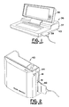
- Figure 1 is a side perspective view of a prior art laptop computer illustrating a PC card connection means.
- Figure 2 is a side perspective view of a prior art body-worn or body-supported computer illustrating a PC card connection means used therein.
- Figure 3 is a left top perspective view of the convertible body-worn or body-supported computer of this invention with the PC card connector cable extending from the PC card compartment.
- Figure 4 is a left top perspective view of the convertible body-worn or body-supported computer of this invention illustrating the PC card compartment when the access door is opened.
- Figure 5 is a bottom perspective view of the convertible body-worn or body-supported computer illustrating the hard drive access compartment closure.
- Figure 6 is a right bottom perspective view of the convertible body-worn or body-supported computer illustrating the connectors for peripherals and the recessed location of the computer connector means.
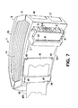
- Figure 7 is a right bottom perspective view of the convertible body-worn or body-supported computer illustrating the recessed connector means without the connection thereto of the connector.
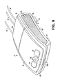
- Figure 8 is a top front perspective view of the body-worn or body-supported computer 1 illustrating the IrDA port.
- FIG 1 a laptop computer 36 as well known in the prior art is illustrated.
- the laptop 36 has the conventional components of a computer including a computer laptop housing 37 and a monitor 38.
- the PCMCIA (PC card) card 39 is shown as conventionally used and attached in a laptop 36. It can be seen in figure 1 that PC card 39 is extending to a large degree outside of the housing 37 which exposes it to damage if contacted by any substantial force.
- a prior art mobile computer 40 is shown with PC card slot openings 41 which are adapted to receive PC cards 42.
- the PC cards 39 and 42 when in use extend substantially beyond the side terminal portions 43 and 44 of the laptop 36 and mobile computers 40, respectively. In these prior art devices, the PC cards can be easily broken or damaged especially in movable computers thus rendering the computer capability provided by the PCMCIA (PC) card non-functional.
- PCMCIA PCMCIA
- FIG 3 the mobile body-worn or body-supported computer 1 of this invention is shown.
- a lift door 9 is shown which opens into a PC card compartment 26 (as seen in fig. 4).
- the cable 31 connecting from the housed PC card 28 is extended through slot 23.
- the door 9 when open exposes a connection 34 for at least one PCMCIA card(s) (PC cards) 28 (one to four cards). This is an improvement of importance since extending PCMCIA cards (PC cards) shown in figures 1 and 2 can easily be broken or damaged thus rendering the computer capability provided by the PCMCIA card non-functional.
- the PC cards are housed totally within the housing 26 (as seen in fig.
- FIG 3 cable 31 which is connected to card 28 within housing 26 is shown after door 9 is closed to hermetically seal in card 28.
- FIG 3 on the top front portion 10 of the computer housing 2 are central buttons 11 and joy stick or lever 12.
- the lever 12 is used to move and control a mouse pointer when the computer 1 is used as a mobile or conventional computer.
- the control buttons 11 are used for program execution or menu selection when the computer 1 is used as a conventional computer.
- These controls 11 and 12 are clearly illustrated in figs. 3 and 4.
- vent louvers (or a heat sink) 13 which allow the heat from inside the computer housing 2 to be dissipated or vented out to the atmosphere.
- the computer housing 2 is symmetrical so that when it is worn on either the right-hand side or left-hand side of the user's waist, the back section 5, peripheral connector means 3 and cables 4 will always face the back of the user.
- a stationary stand 14 is used to support the front section 10 of the computer.
- This front stand 14 is also used as a belt loop (or handle) as shown in figs. 5, 6 and 7. In figure 5, lift stand 8 is moved down to permit easy connection of cables 4 to outlets 3.
- cables 4 connect to components of a conventional computer such as monitors, keyboards, power supplies or any other desirable component.
- the stand 8 when down permits easy access to conduits 3 and allows the computer 1 to be used on a flat surface as is customary when using a conventional or laptop computer.
- the louvered sides or vents 13 allow heat dissipation in this mode of use.
- buttons 11 are easily accessible to both right and left-handed users.
- the controls of buttons 11 and mouse lever 12 When the computer housing 2 is turned upside down in changing from right-hand to left-hand use, the controls of buttons 11 and mouse lever 12 always face the front of the user for easy access and use. Conversely, when right side 15 is facing up or down when worn, the controls 11 and 12 always face the front cables 4 and outlets 3 always face the back of the user. Controls or software can be provided to convert or reverse the functions of controls or buttons 11.
- Versa Point ® mouse pointing technology may be used as one suitable means in controls 11 and 12.
- Versa Point ® is a trademark of Interlink Electronics of 547 Flynn Rd., Carnarillo, CA 93012.
- Opening 22 is an IrDA port that can be used for wireless communications.
- IrDA (Infra Red Data Association) ports are known, for example, as disclosed in U.S. patent 5,491,651 and other publications. IrDA are used as transceivers (transmit and receive) to communicate with local area networks, with printers, with another computer for transferring of information or data and other desired uses. In the present invention, opening of port 22 is used for access to an IrDA connection.
- FIG 4 a top back view of the computer 1 is shown without the lift stand 8 and front stand 14 for clarity.
- the positioning of offset or recessed bottom extension 6 is shown slightly indented and below back portion 5 of the computer housing 2.
- the curvature 17 of housing 2 which is adjacent to the user's body is shown in figure 4. While figure 4 and the other figures all show (for clarity purposes only) a rectangular configuration for housing 2, other shapes or configurations may be used if desirable. For example, an oval or circular configuration may be used if the other specifics of this invention as claimed are present.
- Openings 16 and 17 provide means for connecting to computer 1 other peripheral equipment such as floppy drives, bar code scanners, VGA port or external monitor connectors.
- Housing 2 preferably is constructed of a lightweight, structurally strong plastic. Outlets 3, any suitable number of them, may be used and are positioned in bottom extension 6 but are not visible in figure 4. Figures 5-7 clearly show the location of these electrical outlets or conduits 3.
- Opening 23 is a cable opening for cables used with PCMCIA card slots.
- the bottom of housing 2 is shown in a preferred embodiment having front stand-front loop 14 located in a position in front 10.
- An easy access door 18 is located in the bottom section and provides an access cover for insertion into the bottom of housing 2 of storage means or non-volatile storage means.
- Four screws (or any other convenient number) 19 are easily removed to permit access therein.
- the bottom of the computer downwardly facing side 20 has positioned therein an access door 18 which covers a removable hard drive compartment. That is, a compartment for housing a removable hard drive. Access to this compartment is obtained by removing screws 19 which permits removal of door 18 and permits an enclosed compartment for a hard drive.
- the entire housing needs to be disassembled to have access to a hard drive compartment.
- a hard drive with a higher capacity than PC card 28 is desirable in many instances.
- the computer 1 of this invention provides this flexibility of using both PC cards 28 and hard drives of high capacity. Ease of removing screws 19 makes use of the optional hard drive compartment convenient for the user.
- Movable lift stand 8 is shown folded up (body-worn or body-supported mode) but is conveniently moved downward as shown in figure 2 (conventional computer mode) when desired. As shown in figure 5, lift stand 8 and front stand 14 act as loops or belt guides when computer 1 is worn around the waist or elsewhere on the user's body. Stands 8 and 14 are shown protruding in an exaggerated manner to show the structure and function; however, any comfortable arrangement may be used for the comfort and convenience of the user.
- Outlet 24 is used to connect a head-mounted display (HMD) or other display means to the computer 1 when it is used as a body-worn or body-supported computer.
- HMD head-mounted display
- offset connectors 24 and 3 are shown curbed to conform to the body of the user (usually the waistline) and also are recessed or offset from the back portion 5 of the computer housing. This is important since the major portion of connector 32 is recessed and protected to prevent damage to the connector(s) 32 when worn. Not only is the recessed connector 24 desirable but also its curvature to conform to a wearer's waist is important for both comfort and durability. When body (or waist) worn rigid connectors are worn parallel with the user's waist they will be exposed to less possibility of damage and, as noted, are more comfortable.
- Figure 6 shows connector 32 when attached to the outlet 24 where the outer portion of connector 32 which is connected to cable 33 does not extend much beyond the back portion 5 of the computer housing 2.
- Connectors 24 and 3 are used in this mobile computer 1 to connect to a headset or display means and to power sources and, when needed, to a keyboard.
- the computer 1 is used with hands-free activation means as disclosed in U.S. Patent 5,305,244.
- the computer 1 may be used by right and left-handed users. This is accomplished since, as earlier mentioned, the computer housing is symmetrical.
- “Symmetrical” as used herein means symmetry of longitudinal sides 15 (top) and (bottom) 20, i.e. are alike in size, shape and position. Left side 20 in figure 7 is facing downward.
- the computer 1 is shown in a position when used as a mobile body-worn or body-supported computer around the waist of a user.
- a belt 45 encircles the waistline of the user with computer 1 occupying only a portion of the waistline unlike the computer of Janik I and II which encircles and occupies substantially the entire waistline.
- all of the computer components necessary for a conventional computer are compactly located in one housing, i.e. housing 2 in the present invention.
- the cables 31 and 33 always face the back or rear of the user so that they are out of the way when the user is using his or her hands for the task at hand, i.e. repairing a machine, etc.
- the term "waist” or "waistline” it is understood to include other parts of the human body in which it would be desirable to wear this computer.
Landscapes
- Engineering & Computer Science (AREA)
- Theoretical Computer Science (AREA)
- Computer Hardware Design (AREA)
- General Engineering & Computer Science (AREA)
- General Physics & Mathematics (AREA)
- Physics & Mathematics (AREA)
- Human Computer Interaction (AREA)
- Power Engineering (AREA)
- Casings For Electric Apparatus (AREA)
- Calculators And Similar Devices (AREA)
- Credit Cards Or The Like (AREA)
- Iron Core Of Rotating Electric Machines (AREA)
- Control Of Eletrric Generators (AREA)
- Gyroscopes (AREA)
- Superconductors And Manufacturing Methods Therefor (AREA)
Abstract
Description
- This invention relates to a computer and, more specifically, to a computer having a novel PCMCIA housing and other novel features. This application is related to our EP-A-0,827,061.
- Most, if not all, of the computers used today have means to use PCMCIA cards and thereby also have PCMCIA card connection means. The PCMCIA card (PC card) is generally connected to the computer housing at one terminal end portion of the housing whereby a portion of the PC card structure or attachment extends beyond said terminal end portion.
- PCMCIA or PC cards are traditionally made up of two parts. The first part is the PC card itself. It usually contains all the electronics necessary for performing a given function, e.g. modem communications. The second part (sometimes called a dongle or cable), is the connector and sometimes wire that attaches to the PC card on one end hereinafter referred to as the "second part" and on the other end of the wire is a second connector that attaches to a device such as standard telephone wiring. The combination structure of both this first part and second part will hereinafter be referred to as the "complete" or "entire" PC card.
- One of the many problems that PCMCIA users encounter is the susceptibility of the dongle/cable (at the point where the dongle/cable is physically connected to the PC card) to breaking during normal use. Most computer manufacturers build the PC card housing such that the PC card itself, when inserted into the computer, is embedded within the structure of the computer and is therefore protected. However, the most susceptible part for breaking is where the connector and cable attaches to the PC card. This connector and cable is not protected at all but extends out beyond the computer housing.
- Another problem that is inherent with PCMCIA is that it is difficult to protect PC card slots from enviromnental factors (such as rain and dust) while a PC card is inserted into the computer housing.
- The present invention eliminates the problems above by providing the PC card housing with the ability not only to seal off the connector but also to allow the connector and portion of the cable connected to the PC card to be contained within the housing.
- There are known computers that have been used and disclosed involving wearable computers and computer components. The feature of these prior art computers is that they permit the user to have freedom to use his or her hands for repairing or other functions while using a fully functional computer. One of the most commercially successful and well known of these computers is the Mobile Assistant ® available from Xybernaut Corporation of Fairfax, Virginia. Mobile Assistant ®) is a registered trademark of Xybernaut Corporation (formerly Computer Products & Services, Inc.)
- U.S. Patent 5,305,244 (Newman, et al.) describes the details of the Mobile Assistant ® and fully discloses the components and function of such user-supported computers. Also, EP-A-0,767,417 describes and claims further improvements and modifications to the Mobile Assistant ®. Both U.S. 5,305,244 and EP-A-0,767,417 are owned by the assignee of the present application.
- Also disclosing wearable computers are U.S. Patents 5,285,398 (Janik I) and 5,491,651 (Janik II). Both of these patents disclose a belt computer containing the elements or components of a computer. In Janik I, the plurality of computing elements are located on the belt and a flexible signal relaying means connects all of the elements for computing. A protective covering is used for enclosing said computer elements. In Janik II, a similar belt computer is described and claimed in which the signal relaying means, the length of which between any two computing elements, is greater than the length of the wearable member between any two computing elements. In both Janik 1 and Janik II, the flexible wearable computer is in the form of a belt comprising around its periphery sequentially positioned computer elements.
- In both Newman, et al. and Janik 1 and II, a body-worn computer is disclosed that has utility only as a body-worn mobile computer.
- Also in the prior art, PC cards extend out from the main frame of the computer housing and are often damaged. This is quite frequently the case in mobile, body-worn or body-supported computers where movement of the user is frequent and sometimes extreme.
- It is therefore an object of this invention to provide a computer structure devoid of the above-noted disadvantages.
- Another object of this invention is to provide a computer structure having a housing containing a PC card weather proof compartment that houses substantially the entire PCMCIA (PC card) when in use.
- Yet a further object of this invention is to provide a compartment for a removable hard drive in a reversible mobile computer.
- Still a further object of this invention is to provide a mobile computer that has means for communicating with other means using infrared technology.
- Another object of this invention is to provide a computer structure that can be used as both a mobile computer and a stand alone or desktop computer.
- Another still further object of this invention is to provide a mobile computer having outlets or other means to connect onto or be compatible with components of a stand alone, laptop or desktop computer.
- Yet another object of this invention is to provide a computer structure that contains substantially all of the components needed in a general purpose or conventional computer including but not limited to input/output means, processor means and storage means.
- Other objects will become apparent upon a further reading of this disclosure.
- The above objects and others are accomplished, generally speaking, by providing a mobile, body-worn or body-supported computer comprising a computer housing, activating means, means for attaching said computer housing to a user, said computer housing comprising substantially all of the components of a conventional computer with optionally a monitor, said housing comprising a PC card housing having means to contain substantially an entire PC card when contained therein. Optionally the computer of this invention also could comprise:
- A. a compartment for housing a removable hard drive; and
- B. an opening for internal connection to an IrDA transceiver.
-
- This computer structure is usable as both a mobile body-worn or body-supported computer and as a component for a stand alone, laptop or desktop computer or any other conventional computer. By "conventional computer" is meant any computer known and used today such as those available from IBM, Dell, Apple, Compaq, Toshiba, Micron, Hewlett-Packard, etc. The computer structure of this invention in one body-worn or body-supported embodiment has a computer housing that can be worn around the torso or waist of a user and is curved on its inner side (the side that contacts the user's waist) to be contoured in accordance with the curvature of the user's waist. It has structural dimensions or area that occupies only a portion of said user's waistline. Thus, unlike Janik I and II above discussed, it does not encircle the entire waist of the user. When used as a waist-worn computer, it is important that cables and other electrical connections extend from the back portion of the computer so as to be out of the way and not interfere with the user's hands when he or she is attempting to repair an object or machine or otherwise use their hands. The computer structure is symmetrical; therefore, the computer can be turned upside down as a unit for left-hand operation. The cable outlets in this manner always will face the back of the user. Conversely, the mouse controls (when converted to a conventional desktop or stand alone computer) will always be positioned in the front of the computer housing convenient for the right or left-hand user. The computer of this invention as earlier noted can be a body-supported computer, can be a laptop computer, can be a stand alone or desktop or any other type computer. It can optionally contain a monitor in the same or different structure than the main computer housing. The housing of the computer of this invention has outlets for connection to other components such as power supplies, monitors, keyboards or any other required component. All embodiments of a mobile computer described in EP-A-0,767,417 and U.S. Patent 5,305,244 are included in those structures usable in the present invention with the modification described and claimed herein.
- The embodiment of this invention that includes voice or audio activation when the computer is body-worn or body-supported also includes a body-worn or body-supported display screen such as a head-worn or arm-worn display. Other activation means than audio may be used in the computer of this invention such as eye-tracking activation means, electroencephalography, head or arm tracking means, or keyboard, pen, mouse, touch activation means and mixtures thereof. The computer housing in the present invention includes all of the components found in a conventional computer such as a storage means, processor means, audio transducer and converter means and recognizing means, all of which are described in detail in U.S. Patent 5,305,244. Also included in this embodiment are means for mounting the computer housing onto a user. Generally, attachment is made on a belt worn by a user such as around the waist, over the shoulder or onto a vest or other wearable means. The sides of the computer housing are ribbed or louvered to permit heat to be dissipated from the interior of the housing and to allow proper internal temperature best suited for computer operation. The computer housing generally is made of a lightweight yet rigid plastic or other suitable material. It is contoured or curved to follow the curvature of the human body such as the waistline. The portion of the computer housing that contacts the user's body has a movable stand that doubles as a belt loop (when used as a body-worn or body-supported computer) and a lift stand when used as a conventional computer. The electrical cord conduit connections found in the back portion of the housing are also contoured to parallel the curvature of the waist. Once placed on a flat supporting surface for use as a conventional computer, the conduits would point downwardly at an angle which would make it difficult to connect cables for monitor, power or keyboard connection. To correct for this, a movable lift stand is located on the rear underside of the computer housing. When this lift stand is moved down, it lifts the rear or back portion of the computer housing so that the conduits are on a plane substantially parallel with the supporting surface and are pointed straight out. This allows easy insertion of cables and electrical connectors into the conduits. The front underside of the housing will, in the preferred embodiment, also have a loop through which a belt will fit when attaching to a user. The conduits which are preferably located in the rear side of the housing are used for cable connection to the body or head-mounted display or conventional monitor. Another aperture is used for connection to a power supply and a third aperture may be used for connection to a keyboard when used as a stand alone, laptop or desktop computer.
- When the structure of this invention is used as a conventional computer, there are located on the top section of the housing three movable levers, joy sticks or buttons or other means, one to operate a mouse and the other two for program execution or cursor manipulation. When the mobile function is desired, the top, movable button or lever will always be used in the same manner whether worn on the right or left-hand side of the user.
- An embodiment of the invention will now be described, by way of example, with reference to the accompanying drawings, in which:
- Figure 1 is a side perspective view of a prior art laptop computer illustrating a PC card connection means.
- Figure 2 is a side perspective view of a prior art body-worn or body-supported computer illustrating a PC card connection means used therein.
- Figure 3 is a left top perspective view of the convertible body-worn or body-supported computer of this invention with the PC card connector cable extending from the PC card compartment.
- Figure 4 is a left top perspective view of the convertible body-worn or body-supported computer of this invention illustrating the PC card compartment when the access door is opened.
- Figure 5 is a bottom perspective view of the convertible body-worn or body-supported computer illustrating the hard drive access compartment closure.
- Figure 6 is a right bottom perspective view of the convertible body-worn or body-supported computer illustrating the connectors for peripherals and the recessed location of the computer connector means.
- Figure 7 is a right bottom perspective view of the convertible body-worn or body-supported computer illustrating the recessed connector means without the connection thereto of the connector.
- Figure 8 is a top front perspective view of the body-worn or body-supported computer 1 illustrating the IrDA port.
- In figure 1 a
laptop computer 36 as well known in the prior art is illustrated. Thelaptop 36 has the conventional components of a computer including acomputer laptop housing 37 and amonitor 38. The PCMCIA (PC card)card 39 is shown as conventionally used and attached in alaptop 36. It can be seen in figure 1 thatPC card 39 is extending to a large degree outside of thehousing 37 which exposes it to damage if contacted by any substantial force. Also in figure 2 a prior artmobile computer 40 is shown with PCcard slot openings 41 which are adapted to receivePC cards 42. In both prior art devices shown in figures 1 and 2, thePC cards side terminal portions laptop 36 andmobile computers 40, respectively. In these prior art devices, the PC cards can be easily broken or damaged especially in movable computers thus rendering the computer capability provided by the PCMCIA (PC) card non-functional. - In figure 3 the mobile body-worn or body-supported computer 1 of this invention is shown. In this figure, a
lift door 9 is shown which opens into a PC card compartment 26 (as seen in fig. 4). When thePC card 28 is housed incompartment 26 anddoor 9 is closed, thecable 31 connecting from the housedPC card 28 is extended throughslot 23. In one embodiment of this invention thedoor 9 when open exposes aconnection 34 for at least one PCMCIA card(s) (PC cards) 28 (one to four cards). This is an improvement of importance since extending PCMCIA cards (PC cards) shown in figures 1 and 2 can easily be broken or damaged thus rendering the computer capability provided by the PCMCIA card non-functional. The PC cards are housed totally within the housing 26 (as seen in fig. 4); only the cable orconnector 31 extends out from thehousing 26 anddoor 9 throughslot 23. Also, thehousing 26 permits sealing 30 around the door to make it weatherproof when worn outdoor. Thisinternal housing 26 now provides means to prevent damaging thePC card 28 and means to weatherproof thecard 28 andhousing 26 from rain, water, snow or other inclement conditions. Ejecting means onbuttons 29 are now easier to get to than the prior art buttons which are recessed and are hard to access. In addition, the pressure points on thePC card 28 are reduced in the present embodiment to further minimize damage to thecard 28.Resilient waterproofing seal 30 is used to weatherproof the door and, as noted, protect the interior ofhousing 26 andcard 28 from damage resulting from weather conditions. In figure 3cable 31 which is connected to card 28 withinhousing 26 is shown afterdoor 9 is closed to hermetically seal incard 28. In figure 3 on thetop front portion 10 of thecomputer housing 2 are central buttons 11 and joy stick orlever 12. Thelever 12 is used to move and control a mouse pointer when the computer 1 is used as a mobile or conventional computer. The control buttons 11 are used for program execution or menu selection when the computer 1 is used as a conventional computer. Thesecontrols 11 and 12 are clearly illustrated in figs. 3 and 4. On the sides of the computer 1 are located vent louvers (or a heat sink) 13 which allow the heat from inside thecomputer housing 2 to be dissipated or vented out to the atmosphere. These ribbed side vents orlouvers 13 help reduce the inside heat which heat could cause malfunctioning or slowing down of the computer functions. Thecomputer housing 2 is symmetrical so that when it is worn on either the right-hand side or left-hand side of the user's waist, theback section 5, peripheral connector means 3 and cables 4 will always face the back of the user. When the computer 1 is used or converted into a conventional computer and placed on a flat desk or other surface, astationary stand 14 is used to support thefront section 10 of the computer. Thisfront stand 14 is also used as a belt loop (or handle) as shown in figs. 5, 6 and 7. In figure 5, lift stand 8 is moved down to permit easy connection of cables 4 tooutlets 3. It can be seen that withoutlift stand 8, connection of cables would be very difficult because of the extreme angle ofoutlet conduits 3. When computer 1 is used or converted to a conventional computer, cables 4 connect to components of a conventional computer such as monitors, keyboards, power supplies or any other desirable component. Thestand 8 when down permits easy access toconduits 3 and allows the computer 1 to be used on a flat surface as is customary when using a conventional or laptop computer. The louvered sides or vents 13 allow heat dissipation in this mode of use. - In figures 3, 4 and 8,
top front 10 of the computer is illustrated wherein control buttons 11 are easily accessible to both right and left-handed users. When thecomputer housing 2 is turned upside down in changing from right-hand to left-hand use, the controls of buttons 11 andmouse lever 12 always face the front of the user for easy access and use. Conversely, whenright side 15 is facing up or down when worn, thecontrols 11 and 12 always face the front cables 4 andoutlets 3 always face the back of the user. Controls or software can be provided to convert or reverse the functions of controls or buttons 11. Versa Point ® mouse pointing technology may be used as one suitable means incontrols 11 and 12. Versa Point ® is a trademark of Interlink Electronics of 547 Flynn Rd., Carnarillo, CA 93012.Opening 22 is an IrDA port that can be used for wireless communications. IrDA (Infra Red Data Association) ports are known, for example, as disclosed in U.S. patent 5,491,651 and other publications. IrDA are used as transceivers (transmit and receive) to communicate with local area networks, with printers, with another computer for transferring of information or data and other desired uses. In the present invention, opening ofport 22 is used for access to an IrDA connection. - In figure 4, a top back view of the computer 1 is shown without the
lift stand 8 and front stand 14 for clarity. The positioning of offset or recessedbottom extension 6 is shown slightly indented and belowback portion 5 of thecomputer housing 2. Thecurvature 17 ofhousing 2 which is adjacent to the user's body is shown in figure 4. While figure 4 and the other figures all show (for clarity purposes only) a rectangular configuration forhousing 2, other shapes or configurations may be used if desirable. For example, an oval or circular configuration may be used if the other specifics of this invention as claimed are present.Openings Housing 2 preferably is constructed of a lightweight, structurally strong plastic.Outlets 3, any suitable number of them, may be used and are positioned inbottom extension 6 but are not visible in figure 4. Figures 5-7 clearly show the location of these electrical outlets orconduits 3.Opening 23 is a cable opening for cables used with PCMCIA card slots. - In figure 5, the bottom of
housing 2 is shown in a preferred embodiment having front stand-front loop 14 located in a position infront 10. Aneasy access door 18 is located in the bottom section and provides an access cover for insertion into the bottom ofhousing 2 of storage means or non-volatile storage means. Four screws (or any other convenient number) 19 are easily removed to permit access therein. In figure 7, the bottom of the computer downwardly facingside 20 has positioned therein anaccess door 18 which covers a removable hard drive compartment. That is, a compartment for housing a removable hard drive. Access to this compartment is obtained by removingscrews 19 which permits removal ofdoor 18 and permits an enclosed compartment for a hard drive. In the prior mobile computer, the entire housing needs to be disassembled to have access to a hard drive compartment. A hard drive with a higher capacity thanPC card 28 is desirable in many instances. The computer 1 of this invention provides this flexibility of using bothPC cards 28 and hard drives of high capacity. Ease of removingscrews 19 makes use of the optional hard drive compartment convenient for the user.Movable lift stand 8 is shown folded up (body-worn or body-supported mode) but is conveniently moved downward as shown in figure 2 (conventional computer mode) when desired. As shown in figure 5, liftstand 8 and front stand 14 act as loops or belt guides when computer 1 is worn around the waist or elsewhere on the user's body.Stands Outlet 24 is used to connect a head-mounted display (HMD) or other display means to the computer 1 when it is used as a body-worn or body-supported computer. In figure 5, offsetconnectors back portion 5 of the computer housing. This is important since the major portion ofconnector 32 is recessed and protected to prevent damage to the connector(s) 32 when worn. Not only is the recessedconnector 24 desirable but also its curvature to conform to a wearer's waist is important for both comfort and durability. When body (or waist) worn rigid connectors are worn parallel with the user's waist they will be exposed to less possibility of damage and, as noted, are more comfortable. Figure 6 showsconnector 32 when attached to theoutlet 24 where the outer portion ofconnector 32 which is connected tocable 33 does not extend much beyond theback portion 5 of thecomputer housing 2.Connectors Left side 20 in figure 7 is facing downward. - In figures 6 and 7, the computer 1 is shown in a position when used as a mobile body-worn or body-supported computer around the waist of a user. A
belt 45 encircles the waistline of the user with computer 1 occupying only a portion of the waistline unlike the computer of Janik I and II which encircles and occupies substantially the entire waistline. Also, all of the computer components necessary for a conventional computer are compactly located in one housing, i.e.housing 2 in the present invention. Notice that, as earlier stated, thecables
Claims (13)
- A computer structure comprising a computer housing and activating means, said computer housing comprising substantially all of the components of a conventional computer and optionally including a monitor, said housing comprising a PC card housing having means to contain substantially an entire PC card.
- The computer structure of claim 1 wherein said housing comprises a compartment for housing a removable hard drive.
- The computer structure of claim 1 or claim 2 wherein said housing comprises at least one opening for internal connection to an IrDA transceiver.
- The computer structure of any one of claims 1 to 3 wherein said computer housing is body-supported.
- The computer structure of any one of claims 1 to 3 wherein said computer structure is a laptop computer.
- The computer structure of any one of claims 1 to 3 wherein said computer structure is a desktop computer.
- The computer structure of any one of claims 1 to 6 wherein said computer housing has peripheral connector means on its back portion.
- The computer structure of any one of claims 1 to 7 wherein said housing has mouse control means on its front portion.
- The computer structure of any one of claims 1 to 8 having means to be used with equipment of a stand alone computer including a power supply, a keyboard or monitor.
- The computer structure of claim 1 comprising a computer body-supported housing, activating means, means for supporting said computer housing on a user, said computer housing comprising substantially all of the components of a conventional computer with or without a monitor, said housing having a compartment with removable closure means for housing a removable hard drive or other non-volatile storage means, said compartment located in said housing at a location that will permit easy opening and closing of said removable closure means.
- A mobile, body-worn or body-supported computer comprising a computer housing, activation means, means for attaching said computer housing to a user, said computer housing having a front and a back portion, means for wearing said computer housing on the right or left side of a user whereby said front and said back portions are always positioned in the same direction, means for converting said computer from a body-worn or body-supported mobile computer to means to be used with equipment of a stand alone computer, said computer housing containing substantially all of the components of a conventional computer with optionally a monitor, said body-worn or body-supported computer housing comprising a PC card housing having means to contain substantially an entire PC card when contained therein;(A) a compartment for housing a removable hard drive; and(B) an opening for internal connection to an IrDA transceiver.
- The computer of claim 11 having means to convert said body-worn or body-supported computer to a conventional stand alone computer which is integral with said computer housing.
- The computer of any one of claims 1 to 12 wherein said activation means is selected from the group consisting of audio activation means, eye-tracking activation means, electroencephalography, head or arm tracking means, a keyboard, pen, mouse, touch activation means, and mixtures thereof.
Applications Claiming Priority (2)
| Application Number | Priority Date | Filing Date | Title |
|---|---|---|---|
| US97596497A | 1997-11-21 | 1997-11-21 | |
| US975964 | 1997-11-21 |
Publications (3)
| Publication Number | Publication Date |
|---|---|
| EP0918276A2 true EP0918276A2 (en) | 1999-05-26 |
| EP0918276A3 EP0918276A3 (en) | 1999-09-15 |
| EP0918276B1 EP0918276B1 (en) | 2007-01-17 |
Family
ID=25523587
Family Applications (1)
| Application Number | Title | Priority Date | Filing Date |
|---|---|---|---|
| EP98309259A Expired - Lifetime EP0918276B1 (en) | 1997-11-21 | 1998-11-12 | Wearable computer |
Country Status (11)
| Country | Link |
|---|---|
| US (1) | US6351388B1 (en) |
| EP (1) | EP0918276B1 (en) |
| JP (1) | JP3765679B2 (en) |
| KR (1) | KR19990045371A (en) |
| CN (1) | CN1218229A (en) |
| AT (1) | ATE352060T1 (en) |
| AU (1) | AU708668B2 (en) |
| CA (1) | CA2252781A1 (en) |
| DE (1) | DE69836895T2 (en) |
| IL (1) | IL126913A0 (en) |
| TW (1) | TW419624B (en) |
Cited By (2)
| Publication number | Priority date | Publication date | Assignee | Title |
|---|---|---|---|---|
| EP1256866A2 (en) * | 2001-05-08 | 2002-11-13 | Xybernaut Corporation | Mobile computer |
| EP1286245A1 (en) * | 2001-08-17 | 2003-02-26 | Xybernaut Corporation | Wearable computer system |
Families Citing this family (18)
| Publication number | Priority date | Publication date | Assignee | Title |
|---|---|---|---|---|
| CA2357236C (en) * | 2000-10-17 | 2011-09-06 | Spx Development Corporation | Plug-in module for portable computing device |
| JP2003029870A (en) * | 2001-07-12 | 2003-01-31 | Toshiba Corp | Portable information terminal |
| US6943755B1 (en) | 2002-10-07 | 2005-09-13 | Analog Devices, Inc. | Card-enabled, head-wearable secondary display systems |
| GB0306784D0 (en) | 2003-03-25 | 2003-04-30 | Stolt Offshore Ltd | Apparatus and methods for laying elongate articles from a vessel |
| US7265970B2 (en) * | 2003-10-01 | 2007-09-04 | Adwalker (Ip) Limited | Apparatus |
| WO2005069530A1 (en) * | 2004-01-05 | 2005-07-28 | Oqo Incorporated | Connector including electronic device |
| US7097472B2 (en) * | 2004-09-08 | 2006-08-29 | Hewlett-Packard Development Company, L.P. | Universal serial bus plug |
| TWI252725B (en) * | 2004-10-01 | 2006-04-01 | Datastor Technology Co Ltd | Portable device with a storage box containing a data access device |
| KR20130095855A (en) * | 2005-05-11 | 2013-08-28 | 퀄컴 인코포레이티드 | Distributed processing system and method |
| US9455844B2 (en) | 2005-09-30 | 2016-09-27 | Qualcomm Incorporated | Distributed processing system and method |
| US7804691B1 (en) | 2006-05-18 | 2010-09-28 | Utility Associates, Inc. | Assembly for protecting PC cards and peripheral connectors |
| US20080094785A1 (en) * | 2006-10-20 | 2008-04-24 | First Data Corporation | Communication device housing systems and methods |
| US20080111792A1 (en) * | 2006-11-15 | 2008-05-15 | Acco Brands Usa Llc | Input device including wireless and wired modes |
| CN201781135U (en) * | 2010-07-27 | 2011-03-30 | 国基电子(上海)有限公司 | Electronic device |
| US9265458B2 (en) | 2012-12-04 | 2016-02-23 | Sync-Think, Inc. | Application of smooth pursuit cognitive testing paradigms to clinical drug development |
| US9380976B2 (en) | 2013-03-11 | 2016-07-05 | Sync-Think, Inc. | Optical neuroinformatics |
| US20150227177A1 (en) * | 2014-02-12 | 2015-08-13 | AMES ADT, Inc. | Tablet computer and method for coupling a computer cable to the tablet computer |
| CN112068648A (en) * | 2020-08-26 | 2020-12-11 | 广西钦州宇欣电子科技有限公司 | Embedded computer with rich I/O interface |
Citations (3)
| Publication number | Priority date | Publication date | Assignee | Title |
|---|---|---|---|---|
| WO1994022242A1 (en) * | 1993-03-24 | 1994-09-29 | Universal Electronics, Inc. | Infrared remote control device for a personal digital assistant |
| US5689654A (en) * | 1992-06-29 | 1997-11-18 | Elonex F.P. Holdings, Ltd. | Digital assistant system including a host computer with a docking bay for the digital assistant wherein a heat sink is moved into contact with a docked digital assistant for cooling the digital assistant |
| EP0825515A1 (en) * | 1996-08-15 | 1998-02-25 | Xybernaut Corporation | Body-worn computer |
Family Cites Families (27)
| Publication number | Priority date | Publication date | Assignee | Title |
|---|---|---|---|---|
| US5514861A (en) * | 1988-05-11 | 1996-05-07 | Symbol Technologies, Inc. | Computer and/or scanner system mounted on a glove |
| US5305181A (en) * | 1989-05-15 | 1994-04-19 | Norand Corporation | Arm or wrist mounted terminal with a flexible housing |
| CA2014122A1 (en) * | 1990-04-06 | 1991-10-06 | Hertz Ho | Laptop computer with detachable interface card |
| JPH05199342A (en) * | 1991-05-20 | 1993-08-06 | Xerox Corp | Apparatus and method for portable communication by silent handwriting |
| US5305244B2 (en) * | 1992-04-06 | 1997-09-23 | Computer Products & Services I | Hands-free user-supported portable computer |
| US6099329A (en) * | 1992-04-08 | 2000-08-08 | 3Com Corporation | Retractable coaxial jack |
| US5285398A (en) * | 1992-05-15 | 1994-02-08 | Mobila Technology Inc. | Flexible wearable computer |
| US5491651A (en) * | 1992-05-15 | 1996-02-13 | Key, Idea Development | Flexible wearable computer |
| US5579487A (en) * | 1992-10-02 | 1996-11-26 | Teletransaction, Inc. | Portable work slate computer with multiple docking positions for interchangeably receiving removable modules |
| US5666530A (en) * | 1992-12-02 | 1997-09-09 | Compaq Computer Corporation | System for automatic synchronization of common file between portable computer and host computer via communication channel selected from a plurality of usable channels there between |
| US5432510A (en) * | 1993-03-22 | 1995-07-11 | Matthews; Walter S. | Ambidextrous single hand chordic data management device |
| US5416310A (en) * | 1993-05-28 | 1995-05-16 | Symbol Technologies, Inc. | Computer and/or scanner system incorporated into a garment |
| US5416730A (en) * | 1993-11-19 | 1995-05-16 | Appcon Technologies, Inc. | Arm mounted computer |
| US5555490A (en) * | 1993-12-13 | 1996-09-10 | Key Idea Development, L.L.C. | Wearable personal computer system |
| US5572401A (en) * | 1993-12-13 | 1996-11-05 | Key Idea Development L.L.C. | Wearable personal computer system having flexible battery forming casing of the system |
| US5606732A (en) * | 1994-04-26 | 1997-02-25 | Rockwell International Corporation | Direct connect radio and antenna assembly |
| JPH0864315A (en) * | 1994-08-02 | 1996-03-08 | Molex Inc | Receptacle type electricity connector |
| US5848298A (en) * | 1995-02-21 | 1998-12-08 | Intel Corporation | System having two PC cards in a hinged carrying case with battery compartment within in the hinge section |
| JPH0934592A (en) * | 1995-07-19 | 1997-02-07 | Hitachi Ltd | Information processor |
| US5812371A (en) * | 1995-07-25 | 1998-09-22 | Compal Electronics, Inc. | Orientation-adjustable infrared transceiver used in a notebook type computer |
| US5845282A (en) * | 1995-08-07 | 1998-12-01 | Apple Computer, Inc. | Method and apparatus for remotely accessing files from a desktop computer using a personal digital assistant |
| JPH09114543A (en) * | 1995-10-02 | 1997-05-02 | Xybernaut Corp | Handfree computer system |
| JPH0999991A (en) * | 1995-10-03 | 1997-04-15 | Dai Ichi Denshi Kogyo Kk | Card holder |
| US5761485A (en) * | 1995-12-01 | 1998-06-02 | Munyan; Daniel E. | Personal electronic book system |
| TW395121B (en) * | 1996-02-26 | 2000-06-21 | Seiko Epson Corp | Personal wearing information display device and the display method using such device |
| US5909586A (en) * | 1996-11-06 | 1999-06-01 | The Foxboro Company | Methods and systems for interfacing with an interface powered I/O device |
| US6149450A (en) * | 1997-05-21 | 2000-11-21 | Itt Manufacturing Enterprises, Inc. | Smart card adapter latch |
-
1998
- 1998-10-30 AU AU89624/98A patent/AU708668B2/en not_active Ceased
- 1998-11-04 CA CA002252781A patent/CA2252781A1/en not_active Abandoned
- 1998-11-05 IL IL12691398A patent/IL126913A0/en unknown
- 1998-11-11 TW TW087118793A patent/TW419624B/en not_active IP Right Cessation
- 1998-11-11 JP JP32100098A patent/JP3765679B2/en not_active Expired - Fee Related
- 1998-11-12 EP EP98309259A patent/EP0918276B1/en not_active Expired - Lifetime
- 1998-11-12 AT AT98309259T patent/ATE352060T1/en not_active IP Right Cessation
- 1998-11-12 DE DE69836895T patent/DE69836895T2/en not_active Expired - Fee Related
- 1998-11-18 KR KR1019980049383A patent/KR19990045371A/en not_active Application Discontinuation
- 1998-11-23 CN CN98122633A patent/CN1218229A/en active Pending
-
1999
- 1999-12-07 US US09/455,642 patent/US6351388B1/en not_active Expired - Lifetime
Patent Citations (3)
| Publication number | Priority date | Publication date | Assignee | Title |
|---|---|---|---|---|
| US5689654A (en) * | 1992-06-29 | 1997-11-18 | Elonex F.P. Holdings, Ltd. | Digital assistant system including a host computer with a docking bay for the digital assistant wherein a heat sink is moved into contact with a docked digital assistant for cooling the digital assistant |
| WO1994022242A1 (en) * | 1993-03-24 | 1994-09-29 | Universal Electronics, Inc. | Infrared remote control device for a personal digital assistant |
| EP0825515A1 (en) * | 1996-08-15 | 1998-02-25 | Xybernaut Corporation | Body-worn computer |
Non-Patent Citations (1)
| Title |
|---|
| A. SMAILAGIC ET AL.: "The VuMan 2 Wearable Computer" IEEE DESIGN & TEST OF COMPUTERS, vol. 10, no. 3, September 1993 (1993-09), pages 56-67, XP000397411 Los Alamitos, CA, US * |
Cited By (3)
| Publication number | Priority date | Publication date | Assignee | Title |
|---|---|---|---|---|
| EP1256866A2 (en) * | 2001-05-08 | 2002-11-13 | Xybernaut Corporation | Mobile computer |
| EP1256866A3 (en) * | 2001-05-08 | 2005-11-16 | Xybernaut Corporation | Mobile computer |
| EP1286245A1 (en) * | 2001-08-17 | 2003-02-26 | Xybernaut Corporation | Wearable computer system |
Also Published As
| Publication number | Publication date |
|---|---|
| TW419624B (en) | 2001-01-21 |
| CA2252781A1 (en) | 1999-05-21 |
| AU708668B2 (en) | 1999-08-12 |
| US6351388B1 (en) | 2002-02-26 |
| EP0918276A3 (en) | 1999-09-15 |
| KR19990045371A (en) | 1999-06-25 |
| DE69836895T2 (en) | 2007-11-08 |
| ATE352060T1 (en) | 2007-02-15 |
| CN1218229A (en) | 1999-06-02 |
| DE69836895D1 (en) | 2007-03-08 |
| IL126913A0 (en) | 1999-09-22 |
| JPH11353055A (en) | 1999-12-24 |
| JP3765679B2 (en) | 2006-04-12 |
| EP0918276B1 (en) | 2007-01-17 |
| AU8962498A (en) | 1999-06-10 |
Similar Documents
| Publication | Publication Date | Title |
|---|---|---|
| US5719744A (en) | Torso-worn computer without a monitor | |
| EP0918276B1 (en) | Wearable computer | |
| US6304459B1 (en) | Mobile computer | |
| US6529372B1 (en) | Wearable computer-battery system | |
| US6850224B2 (en) | Wearable ergonomic computer mouse | |
| US6262889B1 (en) | Insulated mobile computer | |
| AU753586B1 (en) | Mobile computer | |
| EP0827061B1 (en) | Mobile computer | |
| MXPA98008285A (en) | Wearable computer | |
| JP2003140771A (en) | Portable information equipment attached to arm |
Legal Events
| Date | Code | Title | Description |
|---|---|---|---|
| PUAI | Public reference made under article 153(3) epc to a published international application that has entered the european phase |
Free format text: ORIGINAL CODE: 0009012 |
|
| AK | Designated contracting states |
Kind code of ref document: A2 Designated state(s): AT BE CH DE DK ES FR GB IE IT LI NL PT SE |
|
| AX | Request for extension of the european patent |
Free format text: AL;LT;LV;MK;RO;SI |
|
| PUAL | Search report despatched |
Free format text: ORIGINAL CODE: 0009013 |
|
| AK | Designated contracting states |
Kind code of ref document: A3 Designated state(s): AT BE CH CY DE DK ES FI FR GB GR IE IT LI LU MC NL PT SE |
|
| AX | Request for extension of the european patent |
Free format text: AL;LT;LV;MK;RO;SI |
|
| 17P | Request for examination filed |
Effective date: 20000309 |
|
| AKX | Designation fees paid |
Free format text: AT BE CH DE DK ES FR GB IE IT LI NL PT SE |
|
| 17Q | First examination report despatched |
Effective date: 20020919 |
|
| GRAP | Despatch of communication of intention to grant a patent |
Free format text: ORIGINAL CODE: EPIDOSNIGR1 |
|
| GRAC | Information related to communication of intention to grant a patent modified |
Free format text: ORIGINAL CODE: EPIDOSCIGR1 |
|
| GRAS | Grant fee paid |
Free format text: ORIGINAL CODE: EPIDOSNIGR3 |
|
| GRAA | (expected) grant |
Free format text: ORIGINAL CODE: 0009210 |
|
| AK | Designated contracting states |
Kind code of ref document: B1 Designated state(s): AT BE CH DE DK ES FR GB IE IT LI NL PT SE |
|
| PG25 | Lapsed in a contracting state [announced via postgrant information from national office to epo] |
Ref country code: NL Free format text: LAPSE BECAUSE OF FAILURE TO SUBMIT A TRANSLATION OF THE DESCRIPTION OR TO PAY THE FEE WITHIN THE PRESCRIBED TIME-LIMIT Effective date: 20070117 Ref country code: LI Free format text: LAPSE BECAUSE OF FAILURE TO SUBMIT A TRANSLATION OF THE DESCRIPTION OR TO PAY THE FEE WITHIN THE PRESCRIBED TIME-LIMIT Effective date: 20070117 Ref country code: DK Free format text: LAPSE BECAUSE OF FAILURE TO SUBMIT A TRANSLATION OF THE DESCRIPTION OR TO PAY THE FEE WITHIN THE PRESCRIBED TIME-LIMIT Effective date: 20070117 Ref country code: CH Free format text: LAPSE BECAUSE OF FAILURE TO SUBMIT A TRANSLATION OF THE DESCRIPTION OR TO PAY THE FEE WITHIN THE PRESCRIBED TIME-LIMIT Effective date: 20070117 Ref country code: AT Free format text: LAPSE BECAUSE OF FAILURE TO SUBMIT A TRANSLATION OF THE DESCRIPTION OR TO PAY THE FEE WITHIN THE PRESCRIBED TIME-LIMIT Effective date: 20070117 |
|
| REG | Reference to a national code |
Ref country code: GB Ref legal event code: FG4D |
|
| REG | Reference to a national code |
Ref country code: CH Ref legal event code: EP |
|
| REG | Reference to a national code |
Ref country code: IE Ref legal event code: FG4D |
|
| REF | Corresponds to: |
Ref document number: 69836895 Country of ref document: DE Date of ref document: 20070308 Kind code of ref document: P |
|
| PG25 | Lapsed in a contracting state [announced via postgrant information from national office to epo] |
Ref country code: SE Free format text: LAPSE BECAUSE OF FAILURE TO SUBMIT A TRANSLATION OF THE DESCRIPTION OR TO PAY THE FEE WITHIN THE PRESCRIBED TIME-LIMIT Effective date: 20070417 |
|
| PG25 | Lapsed in a contracting state [announced via postgrant information from national office to epo] |
Ref country code: ES Free format text: LAPSE BECAUSE OF FAILURE TO SUBMIT A TRANSLATION OF THE DESCRIPTION OR TO PAY THE FEE WITHIN THE PRESCRIBED TIME-LIMIT Effective date: 20070428 |
|
| PG25 | Lapsed in a contracting state [announced via postgrant information from national office to epo] |
Ref country code: PT Free format text: LAPSE BECAUSE OF FAILURE TO SUBMIT A TRANSLATION OF THE DESCRIPTION OR TO PAY THE FEE WITHIN THE PRESCRIBED TIME-LIMIT Effective date: 20070618 |
|
| NLV1 | Nl: lapsed or annulled due to failure to fulfill the requirements of art. 29p and 29m of the patents act | ||
| REG | Reference to a national code |
Ref country code: CH Ref legal event code: PL |
|
| PLBE | No opposition filed within time limit |
Free format text: ORIGINAL CODE: 0009261 |
|
| STAA | Information on the status of an ep patent application or granted ep patent |
Free format text: STATUS: NO OPPOSITION FILED WITHIN TIME LIMIT |
|
| 26N | No opposition filed |
Effective date: 20071018 |
|
| PG25 | Lapsed in a contracting state [announced via postgrant information from national office to epo] |
Ref country code: BE Free format text: LAPSE BECAUSE OF FAILURE TO SUBMIT A TRANSLATION OF THE DESCRIPTION OR TO PAY THE FEE WITHIN THE PRESCRIBED TIME-LIMIT Effective date: 20070117 |
|
| PG25 | Lapsed in a contracting state [announced via postgrant information from national office to epo] |
Ref country code: IT Free format text: LAPSE BECAUSE OF FAILURE TO SUBMIT A TRANSLATION OF THE DESCRIPTION OR TO PAY THE FEE WITHIN THE PRESCRIBED TIME-LIMIT Effective date: 20070117 Ref country code: FR Free format text: LAPSE BECAUSE OF FAILURE TO SUBMIT A TRANSLATION OF THE DESCRIPTION OR TO PAY THE FEE WITHIN THE PRESCRIBED TIME-LIMIT Effective date: 20070907 |
|
| PG25 | Lapsed in a contracting state [announced via postgrant information from national office to epo] |
Ref country code: IE Free format text: LAPSE BECAUSE OF NON-PAYMENT OF DUE FEES Effective date: 20071112 |
|
| PG25 | Lapsed in a contracting state [announced via postgrant information from national office to epo] |
Ref country code: FR Free format text: LAPSE BECAUSE OF FAILURE TO SUBMIT A TRANSLATION OF THE DESCRIPTION OR TO PAY THE FEE WITHIN THE PRESCRIBED TIME-LIMIT Effective date: 20070117 |
|
| PGFP | Annual fee paid to national office [announced via postgrant information from national office to epo] |
Ref country code: DE Payment date: 20081218 Year of fee payment: 11 |
|
| PGFP | Annual fee paid to national office [announced via postgrant information from national office to epo] |
Ref country code: GB Payment date: 20081107 Year of fee payment: 11 |
|
| GBPC | Gb: european patent ceased through non-payment of renewal fee |
Effective date: 20091112 |
|
| PG25 | Lapsed in a contracting state [announced via postgrant information from national office to epo] |
Ref country code: DE Free format text: LAPSE BECAUSE OF NON-PAYMENT OF DUE FEES Effective date: 20100601 |
|
| PG25 | Lapsed in a contracting state [announced via postgrant information from national office to epo] |
Ref country code: GB Free format text: LAPSE BECAUSE OF NON-PAYMENT OF DUE FEES Effective date: 20091112 |