EP0911119A2 - Method for determining the installed torque in a screw joint at impulse tightening and a torque impulse tool for tightening a screw joint to a predetermined torque level - Google Patents
Method for determining the installed torque in a screw joint at impulse tightening and a torque impulse tool for tightening a screw joint to a predetermined torque level Download PDFInfo
- Publication number
- EP0911119A2 EP0911119A2 EP98850165A EP98850165A EP0911119A2 EP 0911119 A2 EP0911119 A2 EP 0911119A2 EP 98850165 A EP98850165 A EP 98850165A EP 98850165 A EP98850165 A EP 98850165A EP 0911119 A2 EP0911119 A2 EP 0911119A2
- Authority
- EP
- European Patent Office
- Prior art keywords
- torque
- screw joint
- impulse
- rotational movement
- value
- Prior art date
- Legal status (The legal status is an assumption and is not a legal conclusion. Google has not performed a legal analysis and makes no representation as to the accuracy of the status listed.)
- Granted
Links
Images


Classifications
-
- B—PERFORMING OPERATIONS; TRANSPORTING
- B25—HAND TOOLS; PORTABLE POWER-DRIVEN TOOLS; MANIPULATORS
- B25B—TOOLS OR BENCH DEVICES NOT OTHERWISE PROVIDED FOR, FOR FASTENING, CONNECTING, DISENGAGING OR HOLDING
- B25B23/00—Details of, or accessories for, spanners, wrenches, screwdrivers
- B25B23/14—Arrangement of torque limiters or torque indicators in wrenches or screwdrivers
- B25B23/145—Arrangement of torque limiters or torque indicators in wrenches or screwdrivers specially adapted for fluid operated wrenches or screwdrivers
- B25B23/1453—Arrangement of torque limiters or torque indicators in wrenches or screwdrivers specially adapted for fluid operated wrenches or screwdrivers for impact wrenches or screwdrivers
-
- B—PERFORMING OPERATIONS; TRANSPORTING
- B25—HAND TOOLS; PORTABLE POWER-DRIVEN TOOLS; MANIPULATORS
- B25B—TOOLS OR BENCH DEVICES NOT OTHERWISE PROVIDED FOR, FOR FASTENING, CONNECTING, DISENGAGING OR HOLDING
- B25B23/00—Details of, or accessories for, spanners, wrenches, screwdrivers
- B25B23/14—Arrangement of torque limiters or torque indicators in wrenches or screwdrivers
- B25B23/1405—Arrangement of torque limiters or torque indicators in wrenches or screwdrivers for impact wrenches or screwdrivers
Abstract
In a tightening process quality check application of the above described basic method, the accomplished angular displacements of the joint at repeated impulses are indicated and added, and high and low limit values for the final installed torque and the total angle of rotation are provided and compared to the actually obtained values. A torque impulse delivering power tool comprising an impulse generator (12) with an output shaft (13) having a torque transducer (23) and a rotation detecting device (24) both connected to a process control unit (33) in which a device is arranged to provide a torque target value and a comparating circuit is provided to compare the actual value of the installed torque with the target value and to initiate shut-off of the power supply to the power tool as the target value is reached.
Description
- The invention relates to a method and a device for tightening screw joints by the application of a number of succeeding torque impulses. In particular, the invention concerns a method which is intended for controlling and quality checking of impulse tightening processes and which is based on the determination of the installed torque in the screw joint at each one of the applied torque impulses.
- A problem concerned with prior art technique in this field is the difficulty to obtain an accurate measurement of the installed torque and, hence, an accurate final tightening level in the screw joint based on such measurement. One of the reasons behind this problem used to be the lack of reliable torque transducers suitable for torque impulse tools. Although the transducer problem nowadays has been solved, the accuracy problem as regards the installed torque measurement still exists.
- Accordingly, in previously described screw joint tightening methods using torque impulse tools, as described for instance in US Patent No. 5,366,026, the torque delivered by the tightening tool is used for determining the pretension level in the screw joint. The actual torque level during the tightening process has always been determined by measuring the peak values of the delivered torque impulses, and the tightening process has been controlled by comparison of the per impulse increasing peak value with a predetermined value corresponding to a desired tension level in the screw joint.
- This previously described tightening control method, however, still suffers from accuracy problems. One of the reasons is that the torque peak value indicated at each delivered impulse does not correctly reflect the true actual tension level in the screw joint. At a thorough study of the torque impulse application on screw joints, it has been established that the peak of a delivered torque impulse occurs at the beginning of the torque pulse, and that the screw joint continuous to rotate over a further angular distance after that. When the screw joint actually stops rotating, the torque level is in fact substantially lower than the indicated peak value. Since the tension in the screw joint via the pitch of the thread corresponds directly to the angular displacement of the screw, the tension increases as long as the screw joint rotates.
- Accordingly, the above mentioned study showed that the screw joint is tightened over a further angular distance after the torque peak has occurred, and that the actual screw tension in a vast majority of cases corresponds to a considerably lower torque level than the indicated peak level. Hence, the indicated peak torque level is not the same as the installed torque and does not truly reflect the tension in the screw joint. Accordingly, it is not useful as a process control measurement.
- The primary object of the invention is to improve the accuracy of impulse tightening of screw joints by obtaining a more accurate measurement of the installed torque in the screw joint.
- Another object of the invention is to accomplish an improved method for controlling a screw joint tightening process by using the new improved method for measuring the installed torque in the screw joint.
- A still further object of the invention is accomplish an improved method for quality checking the end result of a screw joint tightening process by using the installed torque measurement in accordance with the new method as well as a measurement of the total angular movement of the joint.
- Further objects and advantages of the invention will appear from the following detailed description of a preferred embodiment of the invention with reference to the accompanying drawings.
- On the drawings:
- Fig. 1 shows a side view, partly in section, of a torque impulse delivering tool according to the invention connected to a power supply and process control unit.
- Fig. 2 illustrates schematically, on a larger scale, a fraction of a rotation detecting and angle measuring device comprised in the tool in Fig. 1.
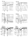
- Fig. 3a and 3b illustrate the rotational movement of the tightening tool output shaft during one discrete impulse as indicated by two separate sensing elements disposed at a relative phase displacement of 90°.
- Fig. 3c illustrates in relation to time the torque delivered to a screw joint as well as the tension obtained during one discrete torque impulse.
- Fig. 4a and 4b illustrate, similarly to Figs. 3a and 3b, the rotational movement of the screw joint during another later impulse.
- Fig. 4c shows, similarly to Fig. 3c, the actual torque and tension development in relation to time at a later torque impulse during the same tightening process.
- Figs. 5a and 5b as well as 6a and 6b illustrate, similarly to Figs. 3a and 3b the rotational movement of the screw joint during two still later impulses during the same tightening process, whereas
- Figs. 5c and 6c show the actual torque and tension development in relation to time during the impulse related angular movements illustrated in Figs. 5a and 5b and 6a and 6b, respectively.
-
- The torque impulse tool shown in Fig. 1 comprises a
housing 10 with apistol type handle 11, a pneumatic rotation motor (not shown) located in thehousing 10, ahydraulic impulse generator 12 connected to the motor, and anoutput shaft 13 connected to theimpulse generator 12. Theoutput shaft 13 is provided with anouter square end 14 for attachment of a nut socket or the like. Thehandle 11 includes in a common way air inlet and outlet passages (not shown) and is provided with athrottle valve 16 as well as a pressure air conduit connection 17 and anexhaust air deflector 18. - The
output shaft 13 is made of a magneto-strictive material and has two circumferential arrays ofrecesses coil assembly 22 form atorque sensing unit 23. This type of torque sensing unit is previously known per se, for instance through the above mentioned US Patent No. 5,366,026, and does not form any part of the invention. - Further, the tool is provided with a
rotation detecting device 24 of the magnetic sensor type which comprises aring element 26 secured to theoutput shaft 13 and asensing unit 27 mounted in thefront section 25 of thehousing 10. Thering element 26 has a circumferential row ofradial teeth 28 disposed at a constant pitch. Thesensing unit 27 is located right opposite thering element 26 and comprises twosensing elements teeth 28. - By the
rotation detecting device 24 it is also possible to obtain information of the amount of angular displacement ϕ of theoutput shaft 13. This is useful for performing a quality check of the end result of the tightening process. Thereby, limit values for the final torque and the total angle of rotation are checked against the actual installed torque and angular displacement measured at the end of the tightening process. - As illustrated in Fig. 2, the
sensing elements circuit board 29 and are disposed side by side at a distance equal to 5/4 of the pitch of theteeth 28. The purpose of such a spacing of thesensing elements output shaft 13. This makes it easier to safely determine the rotational movement of theshaft 13. Alternatively, thesensing elements - However, the
rotation detecting device 24 is previously known per se and does not form any part of the invention. This type of devices is commercially available and is marketed by companies like Siemens AG. - The
torque sensing unit 23 as well as therotation detecting device 24 are both connected to aprocess control unit 33 via amulti-core cable 34 which is connected to the tool via aconnection unit 32. Thecontrol unit 33 comprises means for setting a desired target value for the installed torque in the screw joint as well as limit values for the final torque and the total angle of rotation. Thecontrol unit 33 also contains a comparating circuit for comparing the actual torque value with the set target value, and a circuit for initiating shut-off of the motor power as the actual torque equals the set target value. - The
process control unit 33 is connected to apower supply unit 35 which is incorporated in apressure air conduit 36 connected to the impulse tool and arranged to control the air supply to the motor of the tool. Thepower supply unit 35 is connected to a pressure air source S. - The electronic components and circuitry of the
control unit 33 are not described in detail, because they are of a type commonly used for power tool control purposes. For a person skilled in the power tool control technique, there would not be required any inventive activity to build a control unit once the desired specific functional features are defined. The invention defines those functional features as a method for determining the installed torque in a screw joint being tightened by repeated torque impulses as well as application methods for controlling and monitoring a torque impulse tightening process. - The functional features of the methods according to the invention and the operation order of the impulse tool during a tightening process including a number of successive torque impulses delivered to a screw joint are illustrated by the diagrams 3 a-c to 6a-c. These diagrams are plotted from measurements made during a real tightening process. The diagrams show signals representing the rotational movement of the screw joint as well as measurements representing the torque delivered to the joint and the clamping force or tension magnitude obtained in the joint during four different impulses representing four different tightening stages of the same tightening process.
- The first one of the described impulses delivered to the joint is illustrated in Figs.3a-c. In Fig. 3a, there is shown the rotation related signal delivered by one of the
sensing elements sensing elements teeth 28 passing by thesensing elements output shaft 13. - By studying these curve forms, it is quite easy to determine where the rotation of the joint starts and stops during the impulse. Starting from the left, the curve is straight horizontal. This represents the stand still condition before the rotation starts. The rotation starts at ϕ0, and after a certain increment of rotation illustrated by the repeated wave forms, the rotation stops at ϕI . At this instance, the wave form of the curve does no longer reach its full amplitude. This is clearly illustrated in Fig. 3b. In Fig. 3a, this stop of rotation occurs in one of the inflexion points of the curve and is not possible to determine with certainty whether a stop of rotation actually has taken place. Due to the 900 phase displacement of the
sensing elements - It should be noted that the
output shaft 13 does not come to a complete standstill condition after the stop position ϕI has been reached, which is indicated by the curves in Figs. 3a and 3b not being straight horizontal after that position. The reason for that is a slight rebound movement of theoutput shaft 13 which however does not influence the stop position of the joint. - As described above, the screw joint position at the end of the accomplished rotational increment is marked with ϕI and has a corresponding location in all three diagrams 3a-c.
- In the diagram shown in Fig. 3c, there are illustrated both a signal representing the torque M delivered to the screw joint and a signal representing the obtained clamping force or tension F in the joint. The clamping force F is obtained from a sensor mounted directly on the screw joint. This arrangement is used for experimental purposes only, because if you always have access to the actual clamping force in the joint during tightening the new method for obtaining a more accurate measurement of the installed torque would be meaningless. Accordingly, the clamping force sensor is used just for obtaining a diagrammatical illustration of the tension increase during each impulse, particularly when illustrated in a direct comparison with the torque/time curve.
- It is to be observed that the torque curve is plotted with an increasing torque directed downwards, whereas the tension curve is shown with increasing magnitudes directed upwards. See arrows to the left of the diagram in Fig. 3c.
- From the diagram in Fig. 3c it is evident that the screw joint position ϕI does not coincide with the position in which the peak value MP of the torque is detected. Instead, the diagram shows that the screw joint continues to rotate over a further angular distance after the torque peak magnitude has been detected. This means that the screw joint is subjected to a further increased clamping force, and that the obtained clamping force level corresponds to a much lower torque magnitude than what is represented by the torque peak level MP. The torque magnitude corresponding to the stopping position of the joint is the installed torque and is designated MI.
- In Fig. 3c, there is also illustrated the growth of the clamping force F during a torque impulse delivered to the joint. In the diagram of Fig.3, there is clearly shown that the clamping force F starts increasing as the joint starts rotating and continues to increase until the joint stops rotating, as illustrated by the point ϕI.
- The slight wave form of the torque/time curve, i.e. the occurrence of a second lower peak, is due to dynamic forces and elasticity in the power train of the tightening tool.
- In Figs. 4a-c, 5a-c and 6a-c there are shown curves reflecting the rotational movement of the screw joint as well as the detected torque and clamping force magnitudes during three later torque pulses delivered to the joint during the same tightening process. It is clearly shown that the pulses are successively shorter as the joint is further tightened, and that the secondary torque peak tends to merge with the main torque peak as the tightening process approaches the final pretension condition. See Fig. 6c.
- The four different torque pulses illustrated in Figs. 3a-c, 4a-c, 5a-c and 6a-c, respectively, show clearly by way of examples that the main torque peak value previously used for determining the tightening state of the screw joint does not represent the torque magnitude that corresponds to the obtained clamping force in the joint. Even though at a later tightening stage the rotation stop point ϕI of each impulse is closer to the torque peak point, there is still a substantial difference between the peak level MP and the installed torque MI. See Fig. 6c.
- According to the invention, the per impulse increasing installed torque MI , which is detected at the point where the screw joint rotation ceases at each impulse, is used for determining when the joint is tightened to the predetermined torque target level.
- Moreover, in the diagrams shown in Figs. 3c, 4c, 5c and 6c, there is confirmed that the actual clamping force F actually increases over the angular interval determined by the duration of each impulse. Accordingly, it can be seen that the clamping force F increases from the point ϕ0 in which the rotation starts to the point ϕI in which the rotation ceases.
Claims (6)
- Method for determining the installed torque in a screw joint which is being tightened by a series of repeated torque impulses, comprising the measures of detecting continuously the rotational movement of the screw joint during each impulse,indicating when the rotational movement of the screw joint ceases at each impulse, andindicating at the very instance the rotational movement of the screw joint ceases the value of the actual torque applied on the screw joint.
- Method for controlling a screw joint tightening process wherein the screw joint is to be tightened to a predetermined torque level by means of a torque impulse delivering tool, comprising measuring of the instantaneous value of the torque delivered to the screw joint during each one of a number of succeeding torque impulses delivered to the screw joint, and interrupting the tightening process as a predetermined target value of the applied torque is reached,
characterized by detecting continuously the rotational movement of the screw joint during each one of said torque impulses, indicating when the rotational movement of the screw joint ceases at each impulse, indicating the value of the applied torque at the very instance the rotational movement of the screw joint ceases at each impulse, comparing said indicated postrotation value of the applied torque at each one of a number of succeeding impulses with said predetermined target value, and interrupting the tightening process as said indicated postrotation value of the applied torque has reached said target value. - Method for quality checking of a screw joint tightening process performed by a torque impulse delivering power tool, comprising measuring of the instantaneous torque value as well as the accomplished rotational increment accomplished during each one of a number of succeeding torque impulses, providing high and low limit values for the final torque and the total angle of rotation, comparing at the end of the tightening process the obtained final torque value and the total angle of rotation with said limit values, and providing an indication as to whether said final torque and said total angle of rotation are within said limit values or not as the process is completed, wherein said torque value is measured at the very end of the accomplished rotational increment measured during each one of the delivered torque impulses.
- Method according to claim 3, wherein the rotational increment accomplished at the very first impulse of a series of delivered impulses is measured from a point determined by the torque passing a predetermined threshold value at the start of the impulse.
- Torque impulse delivering power tool for tightening a screw joint to a predetermined torque level, comprising a rotation motor, an output shaft (13) connected to said motor, a rotational movement detecting device (24), a torque transducer (23) for generating a signal in response to the torque delivered via said output shaft (13), and a control unit (33) connected to said rotational movement detecting devices (24) and said torque transducer (23), said control unit (33) including a device for providing a desired torque target value, a comparating circuit arranged to be activated by said rotational movement detecting device (24) to compare said target value with the value of the delivered torque the very instance said rotational movement detecting device (24) indicates that the rotational movement of the screw joint ceases at each delivered impulse, and a motor power shut-off device (35) connected to said comparating circuit and arranged to interrupt the power supply to said motor as the value of the delivered torque equals said torque target value.
- Power tool according to claim 5, wherein said rotational movement detecting device (24) is arranged to generate a rotation angle responsive signal, and said control unit (33) comprises a signal storing and adding device which is connected to said rotational movement detecting device (24) and arranged to store and add successively the rotation angle responsive signals corresponding to the interval of angular displacement detected by said rotational movement detecting device (24) during each impulse, said control unit (33) further comprises a device for providing a target value for the total angular displacement, said signal storing and adding device is connected to said comparating circuit and to said power shut-off device (35) to initiate motor power shut-off as the sum of the stored total angular displacement signals correspond to said target value.
Applications Claiming Priority (2)
| Application Number | Priority Date | Filing Date | Title |
|---|---|---|---|
| SE9703896A SE511336C2 (en) | 1997-10-27 | 1997-10-27 | Method for determining the installed torque in a screw joint during pulse tightening, method for controlling a tightening process, method for quality monitoring and a torque pulse tool for tightening screw joints |
| SE9703896 | 1997-10-27 |
Publications (3)
| Publication Number | Publication Date |
|---|---|
| EP0911119A2 true EP0911119A2 (en) | 1999-04-28 |
| EP0911119A3 EP0911119A3 (en) | 2000-03-29 |
| EP0911119B1 EP0911119B1 (en) | 2002-06-19 |
Family
ID=20408741
Family Applications (1)
| Application Number | Title | Priority Date | Filing Date |
|---|---|---|---|
| EP98850165A Expired - Lifetime EP0911119B1 (en) | 1997-10-27 | 1998-10-22 | Method for determining the installed torque in a screw joint at impulse tightening and a torque impulse tool for tightening a screw joint to a predetermined torque level |
Country Status (5)
| Country | Link |
|---|---|
| US (2) | US6134973A (en) |
| EP (1) | EP0911119B1 (en) |
| JP (1) | JP4564604B2 (en) |
| DE (1) | DE69806113T2 (en) |
| SE (1) | SE511336C2 (en) |
Cited By (13)
| Publication number | Priority date | Publication date | Assignee | Title |
|---|---|---|---|---|
| EP1000710A1 (en) * | 1998-11-16 | 2000-05-17 | Renault | Method of mesuring and/or controlling in a fastening device including a hydropneumatic impulse screw driver |
| EP1059145A2 (en) * | 1999-06-11 | 2000-12-13 | Matsushita Electric Works, Ltd. | Impact-driven rotating device |
| WO2001047669A1 (en) * | 1999-12-23 | 2001-07-05 | Abb Ab | Method, device and system for determining torque |
| EP1250580A1 (en) * | 1999-12-16 | 2002-10-23 | Magna-Lastic Devices, Inc. | Impact tool control method and apparatus and impact tool using the same |
| EP1257034A2 (en) * | 2001-05-09 | 2002-11-13 | Makita Corporation | Power tools |
| WO2004018153A2 (en) * | 2002-08-23 | 2004-03-04 | Fast Technology Ag | Torque sensor adaptor |
| US10052733B2 (en) | 2015-06-05 | 2018-08-21 | Ingersoll-Rand Company | Lighting systems for power tools |
| US10418879B2 (en) | 2015-06-05 | 2019-09-17 | Ingersoll-Rand Company | Power tool user interfaces |
| US10615670B2 (en) | 2015-06-05 | 2020-04-07 | Ingersoll-Rand Industrial U.S., Inc. | Power tool user interfaces |
| US10668614B2 (en) | 2015-06-05 | 2020-06-02 | Ingersoll-Rand Industrial U.S., Inc. | Impact tools with ring gear alignment features |
| EP3632625A4 (en) * | 2017-05-30 | 2020-06-03 | Panasonic Intellectual Property Management Co., Ltd. | Power tool |
| US11260517B2 (en) | 2015-06-05 | 2022-03-01 | Ingersoll-Rand Industrial U.S., Inc. | Power tool housings |
| US11491616B2 (en) | 2015-06-05 | 2022-11-08 | Ingersoll-Rand Industrial U.S., Inc. | Power tools with user-selectable operational modes |
Families Citing this family (32)
| Publication number | Priority date | Publication date | Assignee | Title |
|---|---|---|---|---|
| SE511336C2 (en) * | 1997-10-27 | 1999-09-13 | Atlas Copco Tools Ab | Method for determining the installed torque in a screw joint during pulse tightening, method for controlling a tightening process, method for quality monitoring and a torque pulse tool for tightening screw joints |
| US6581696B2 (en) * | 1998-12-03 | 2003-06-24 | Chicago Pneumatic Tool Company | Processes of determining torque output and controlling power impact tools using a torque transducer |
| US6158528A (en) * | 2000-01-27 | 2000-12-12 | S.P. Air Kabusiki Kaisha | Hand-held pneumatic rotary drive device |
| JP4721535B2 (en) * | 2001-02-28 | 2011-07-13 | 勝行 戸津 | Electric rotary tool |
| SE519292C2 (en) * | 2001-04-17 | 2003-02-11 | Atlas Copco Tools Ab | Method and tool including determination of transmitted torque as a function of deceleration and moment of inertia |
| JP2003200363A (en) * | 2001-12-26 | 2003-07-15 | Makita Corp | Battery type power tool |
| EP1439035A1 (en) * | 2002-12-16 | 2004-07-21 | Fast Technology AG | Signal processing and control device for a power torque tool |
| US7062979B2 (en) * | 2003-03-19 | 2006-06-20 | The Boeing Company | Tool and associated methods for controllably applying torque to a fastener |
| CA2462711C (en) * | 2003-03-31 | 2008-09-02 | Honda Motor Co., Ltd. | Assembly line quality control |
| SE525666C2 (en) * | 2003-07-07 | 2005-03-29 | Atlas Copco Tools Ab | Method for quality assurance of screw joint tightening |
| US6871153B1 (en) * | 2003-11-20 | 2005-03-22 | C.E. Electronics, Inc. | Dynamic calibration qualifier |
| SE526964C2 (en) * | 2003-12-29 | 2005-11-29 | Atlas Copco Tools Ab | Method for functional control of a pneumatic pulse nut puller and a power screwdriver system |
| DE102004003202B4 (en) * | 2004-01-22 | 2022-05-25 | Robert Bosch Gmbh | Handle with detection device |
| SE527512C2 (en) * | 2004-04-01 | 2006-03-28 | Atlas Copco Tools Ab | Method for determining the angular movement of the output shaft of an impulse nut puller when tightening screw joints |
| SE528114C2 (en) * | 2004-09-20 | 2006-09-05 | Atlas Copco Tools Ab | Method for quality control of a screw tightening process carried out by means of an impulse nut puller |
| US7089080B1 (en) * | 2005-08-02 | 2006-08-08 | C.E. Electronics | Pulse tool controller |
| DE102006017193A1 (en) * | 2006-04-12 | 2007-10-25 | Robert Bosch Gmbh | Method for tightening a screw connection and screwing tool |
| DE102007045695A1 (en) * | 2007-09-24 | 2009-04-02 | Hs-Technik Gmbh | Hydropneumatic impulse power screwdriver has hydropneumatic drive provided over electro motor with power for generating torsional impulse, where drive shaft is coupled in bolted connection for transferring torsional impulse |
| DE102007057082A1 (en) * | 2007-11-21 | 2009-05-28 | Newfrey Llc, Newark | Contacting unit, fastening method and screwing tool for carrying out the method |
| SE531828C2 (en) * | 2007-12-05 | 2009-08-18 | Atlas Copco Tools Ab | A power tool and method for using the power tool |
| CN102015216B (en) * | 2008-03-17 | 2013-10-23 | 史丹利百得有限公司 | Discontinous drive tool assembly and method for detecting rotational angle thereof |
| TW200950306A (en) * | 2008-06-10 | 2009-12-01 | Mobiletron Electronics Co Ltd | Electric motor resistance torque control and battery discharging protection circuit |
| DE102009046789A1 (en) * | 2009-11-17 | 2011-05-19 | Robert Bosch Gmbh | Hand machine tool device |
| SE535392C2 (en) * | 2010-09-30 | 2012-07-24 | Atlas Copco Tools Ab | Method for determining the quality of tightening of a screw joint |
| DE102011075859B4 (en) * | 2011-05-16 | 2022-07-07 | Bayerische Motoren Werke Aktiengesellschaft | Tester for impulse wrenches with a test bolt |
| EP2535139B1 (en) * | 2011-06-17 | 2016-04-06 | Dino Paoli S.r.l. | Impact tool |
| DE202011110326U1 (en) * | 2011-09-01 | 2013-07-01 | Hwa Ag | Installation for mounting vehicle wheels |
| US9701000B2 (en) * | 2013-07-19 | 2017-07-11 | Panasonic Intellectual Property Management Co., Ltd. | Impact rotation tool and impact rotation tool attachment |
| US10357871B2 (en) | 2015-04-28 | 2019-07-23 | Milwaukee Electric Tool Corporation | Precision torque screwdriver |
| EP3750671B1 (en) | 2015-04-28 | 2023-02-01 | Milwaukee Electric Tool Corporation | Precision torque screwdriver |
| JP6906196B2 (en) * | 2017-05-30 | 2021-07-21 | パナソニックIpマネジメント株式会社 | Electric tool |
| CN113324862B (en) * | 2021-07-13 | 2022-05-06 | 广东省医疗器械质量监督检验所 | Simulated clinical fatigue resistance testing method and device for peritoneal dialysis external connection tube |
Citations (6)
| Publication number | Priority date | Publication date | Assignee | Title |
|---|---|---|---|---|
| US4185701A (en) * | 1975-05-19 | 1980-01-29 | Sps Technologies, Inc. | Tightening apparatus |
| JPS58132426A (en) * | 1982-02-02 | 1983-08-06 | Nitto Seiko Co Ltd | Automatic screw clamping machine |
| US5094301A (en) * | 1990-01-05 | 1992-03-10 | Dresser Industries, Inc. | Programmable pulsed torque recovery system |
| DE4243069A1 (en) * | 1992-12-18 | 1994-06-23 | Gardner Denver Gmbh | Pulse tool, esp. pulse screwdriver |
| US5366026A (en) * | 1992-08-28 | 1994-11-22 | Nissan Motor Company, Ltd. | Impact type clamping apparatus |
| US5567886A (en) * | 1994-08-18 | 1996-10-22 | Cooper Industries, Inc. | Hydraulic impulse screwdriver particularly for tightening screw connections |
Family Cites Families (12)
| Publication number | Priority date | Publication date | Assignee | Title |
|---|---|---|---|---|
| SE423343B (en) * | 1976-11-22 | 1982-05-03 | Atlas Copco Ab | PROCEDURE AND DEVICE FOR REGULATED TIGHTENING OF SCREW TAPE |
| US4142591A (en) * | 1977-06-29 | 1979-03-06 | S. Himmelstein And Company | Torque-yield control system |
| US4361945A (en) * | 1978-06-02 | 1982-12-07 | Rockwell International Corporation | Tension control of fasteners |
| US4316512A (en) * | 1979-04-04 | 1982-02-23 | Sps Technologies, Inc. | Impact wrench |
| SE446070B (en) * | 1984-12-21 | 1986-08-11 | Atlas Copco Ab | HYDRAULIC TORQUE PULSE FOR TORQUE STRANDING TOOLS |
| SE459327B (en) * | 1984-12-21 | 1989-06-26 | Atlas Copco Ab | HYDRAULIC TORQUE PULSE |
| JP2953211B2 (en) * | 1992-09-07 | 1999-09-27 | 日産自動車株式会社 | Impact type screw tightening device |
| DE4336465A1 (en) * | 1993-10-26 | 1995-04-27 | Bosch Gmbh Robert | Impact or pulse screwing |
| SE506118C2 (en) * | 1993-09-02 | 1997-11-10 | Atlas Copco Tools Ab | Method for tightening threaded joints to a desired bias level by means of a manually operated force nut puller comprising a downward phase and a biasing phase, sensing the torque resistance in the joint and interrupting rotation at the desired bias level reached |
| JPH07308865A (en) * | 1994-05-13 | 1995-11-28 | Nissan Motor Co Ltd | Impact type thread fastening device |
| JPH1071576A (en) * | 1996-06-20 | 1998-03-17 | Nissan Motor Co Ltd | Impact type screw driving method and device |
| SE511336C2 (en) * | 1997-10-27 | 1999-09-13 | Atlas Copco Tools Ab | Method for determining the installed torque in a screw joint during pulse tightening, method for controlling a tightening process, method for quality monitoring and a torque pulse tool for tightening screw joints |
-
1997
- 1997-10-27 SE SE9703896A patent/SE511336C2/en unknown
-
1998
- 1998-10-22 DE DE69806113T patent/DE69806113T2/en not_active Expired - Lifetime
- 1998-10-22 EP EP98850165A patent/EP0911119B1/en not_active Expired - Lifetime
- 1998-10-26 US US09/178,999 patent/US6134973A/en not_active Expired - Lifetime
- 1998-10-27 JP JP30605698A patent/JP4564604B2/en not_active Expired - Lifetime
-
2000
- 2000-08-15 US US09/639,002 patent/US6341533B1/en not_active Expired - Lifetime
Patent Citations (6)
| Publication number | Priority date | Publication date | Assignee | Title |
|---|---|---|---|---|
| US4185701A (en) * | 1975-05-19 | 1980-01-29 | Sps Technologies, Inc. | Tightening apparatus |
| JPS58132426A (en) * | 1982-02-02 | 1983-08-06 | Nitto Seiko Co Ltd | Automatic screw clamping machine |
| US5094301A (en) * | 1990-01-05 | 1992-03-10 | Dresser Industries, Inc. | Programmable pulsed torque recovery system |
| US5366026A (en) * | 1992-08-28 | 1994-11-22 | Nissan Motor Company, Ltd. | Impact type clamping apparatus |
| DE4243069A1 (en) * | 1992-12-18 | 1994-06-23 | Gardner Denver Gmbh | Pulse tool, esp. pulse screwdriver |
| US5567886A (en) * | 1994-08-18 | 1996-10-22 | Cooper Industries, Inc. | Hydraulic impulse screwdriver particularly for tightening screw connections |
Non-Patent Citations (1)
| Title |
|---|
| PATENT ABSTRACTS OF JAPAN vol. 007, no. 246 (M-253), 2 November 1983 (1983-11-02) & JP 58 132426 A (NITSUTOU SEIKOU KK), 6 August 1983 (1983-08-06) * |
Cited By (23)
| Publication number | Priority date | Publication date | Assignee | Title |
|---|---|---|---|---|
| FR2785986A1 (en) * | 1998-11-16 | 2000-05-19 | Renault | METHOD FOR MEASURING AND / OR CONTROLLING TIGHTENING EQUIPMENT INCLUDING A HYDROPNEUMATIC HAMMER SCREWDRIVER |
| EP1000710A1 (en) * | 1998-11-16 | 2000-05-17 | Renault | Method of mesuring and/or controlling in a fastening device including a hydropneumatic impulse screw driver |
| EP1059145A2 (en) * | 1999-06-11 | 2000-12-13 | Matsushita Electric Works, Ltd. | Impact-driven rotating device |
| EP1059145A3 (en) * | 1999-06-11 | 2003-07-16 | Matsushita Electric Works, Ltd. | Impact-driven rotating device |
| EP1250580A4 (en) * | 1999-12-16 | 2006-03-15 | Magna Lastic Devices Inc | Impact tool control method and apparatus and impact tool using the same |
| EP1250580A1 (en) * | 1999-12-16 | 2002-10-23 | Magna-Lastic Devices, Inc. | Impact tool control method and apparatus and impact tool using the same |
| WO2001047669A1 (en) * | 1999-12-23 | 2001-07-05 | Abb Ab | Method, device and system for determining torque |
| EP1257034A2 (en) * | 2001-05-09 | 2002-11-13 | Makita Corporation | Power tools |
| EP1257034A3 (en) * | 2001-05-09 | 2004-04-14 | Makita Corporation | Power tools |
| US7109675B2 (en) | 2001-05-09 | 2006-09-19 | Makita Corporation | Power tools |
| EP2256899A1 (en) * | 2001-05-09 | 2010-12-01 | Makita Corporation | Power tools |
| WO2004018153A3 (en) * | 2002-08-23 | 2004-04-29 | Fast Technology Ag | Torque sensor adaptor |
| WO2004018153A2 (en) * | 2002-08-23 | 2004-03-04 | Fast Technology Ag | Torque sensor adaptor |
| US10418879B2 (en) | 2015-06-05 | 2019-09-17 | Ingersoll-Rand Company | Power tool user interfaces |
| US10052733B2 (en) | 2015-06-05 | 2018-08-21 | Ingersoll-Rand Company | Lighting systems for power tools |
| US10615670B2 (en) | 2015-06-05 | 2020-04-07 | Ingersoll-Rand Industrial U.S., Inc. | Power tool user interfaces |
| US10668614B2 (en) | 2015-06-05 | 2020-06-02 | Ingersoll-Rand Industrial U.S., Inc. | Impact tools with ring gear alignment features |
| US11260517B2 (en) | 2015-06-05 | 2022-03-01 | Ingersoll-Rand Industrial U.S., Inc. | Power tool housings |
| US11491616B2 (en) | 2015-06-05 | 2022-11-08 | Ingersoll-Rand Industrial U.S., Inc. | Power tools with user-selectable operational modes |
| US11602832B2 (en) | 2015-06-05 | 2023-03-14 | Ingersoll-Rand Industrial U.S., Inc. | Impact tools with ring gear alignment features |
| US11707831B2 (en) | 2015-06-05 | 2023-07-25 | Ingersoll-Rand Industrial U.S., Inc. | Power tool housings |
| US11784538B2 (en) | 2015-06-05 | 2023-10-10 | Ingersoll-Rand Industrial U.S., Inc. | Power tool user interfaces |
| EP3632625A4 (en) * | 2017-05-30 | 2020-06-03 | Panasonic Intellectual Property Management Co., Ltd. | Power tool |
Also Published As
| Publication number | Publication date |
|---|---|
| EP0911119A3 (en) | 2000-03-29 |
| US6341533B1 (en) | 2002-01-29 |
| JPH11254340A (en) | 1999-09-21 |
| DE69806113T2 (en) | 2003-01-23 |
| SE9703896L (en) | 1999-04-28 |
| SE9703896D0 (en) | 1997-10-27 |
| JP4564604B2 (en) | 2010-10-20 |
| EP0911119B1 (en) | 2002-06-19 |
| DE69806113D1 (en) | 2002-07-25 |
| US6134973A (en) | 2000-10-24 |
| SE511336C2 (en) | 1999-09-13 |
Similar Documents
| Publication | Publication Date | Title |
|---|---|---|
| US6134973A (en) | Method for determining the installed torque in a screw joint at impulse tightening and a torque impulse tool for tightening a screw joint to a predetermined torque level | |
| US4110829A (en) | Apparatus for and method of determining rotational and linear stiffness | |
| US3982419A (en) | Apparatus for and method of determining rotational and linear stiffness | |
| US4344216A (en) | Apparatus and method for tightening an assembly | |
| US3973434A (en) | Tightening system with quality control apparatus | |
| US9021896B2 (en) | Method for determining the quality of a screw joint tightening process performed by an impulse wrench | |
| GB2048494A (en) | Impact wrench | |
| EP1379361B1 (en) | Method and device for determining the torque applied to the fastener as a function of the retardation and the inertia moment | |
| US7467669B2 (en) | Method for governing the operation of a pneumatic impulse wrench and a power screw joint tightening tool system | |
| GB1577526A (en) | Torquing tool control circuit | |
| US7958611B2 (en) | Method for quality checking a screw joint tightening process performed by a torque impulse wrench | |
| US10668603B2 (en) | Impulse wrench rotation detection | |
| JP2005279865A (en) | Impact type fastening tool | |
| CN214793575U (en) | Bolt clamping force sensor for bolt locking operation | |
| CA1054826A (en) | Apparatus for and method of determining rotational or linear stiffness | |
| JPS628732B2 (en) | ||
| JPS597568A (en) | Power tool |
Legal Events
| Date | Code | Title | Description |
|---|---|---|---|
| PUAI | Public reference made under article 153(3) epc to a published international application that has entered the european phase |
Free format text: ORIGINAL CODE: 0009012 |
|
| AK | Designated contracting states |
Kind code of ref document: A2 Designated state(s): DE FR GB IT |
|
| AX | Request for extension of the european patent |
Free format text: AL;LT;LV;MK;RO;SI |
|
| PUAL | Search report despatched |
Free format text: ORIGINAL CODE: 0009013 |
|
| AK | Designated contracting states |
Kind code of ref document: A3 Designated state(s): AT BE CH CY DE DK ES FI FR GB GR IE IT LI LU MC NL PT SE |
|
| AX | Request for extension of the european patent |
Free format text: AL;LT;LV;MK;RO;SI |
|
| RIC1 | Information provided on ipc code assigned before grant |
Free format text: 7B 25B 23/14 A, 7B 25B 23/145 B, 7B 23P 19/06 B |
|
| 17P | Request for examination filed |
Effective date: 20000826 |
|
| AKX | Designation fees paid |
Free format text: DE FR GB IT |
|
| GRAG | Despatch of communication of intention to grant |
Free format text: ORIGINAL CODE: EPIDOS AGRA |
|
| 17Q | First examination report despatched |
Effective date: 20010319 |
|
| GRAG | Despatch of communication of intention to grant |
Free format text: ORIGINAL CODE: EPIDOS AGRA |
|
| GRAH | Despatch of communication of intention to grant a patent |
Free format text: ORIGINAL CODE: EPIDOS IGRA |
|
| GRAH | Despatch of communication of intention to grant a patent |
Free format text: ORIGINAL CODE: EPIDOS IGRA |
|
| GRAA | (expected) grant |
Free format text: ORIGINAL CODE: 0009210 |
|
| AK | Designated contracting states |
Kind code of ref document: B1 Designated state(s): DE FR GB IT |
|
| REG | Reference to a national code |
Ref country code: GB Ref legal event code: FG4D |
|
| REF | Corresponds to: |
Ref document number: 69806113 Country of ref document: DE Date of ref document: 20020725 |
|
| ET | Fr: translation filed | ||
| PLBE | No opposition filed within time limit |
Free format text: ORIGINAL CODE: 0009261 |
|
| STAA | Information on the status of an ep patent application or granted ep patent |
Free format text: STATUS: NO OPPOSITION FILED WITHIN TIME LIMIT |
|
| 26N | No opposition filed |
Effective date: 20030320 |
|
| REG | Reference to a national code |
Ref country code: FR Ref legal event code: PLFP Year of fee payment: 18 |
|
| REG | Reference to a national code |
Ref country code: DE Ref legal event code: R082 Ref document number: 69806113 Country of ref document: DE Representative=s name: PATENTANWAELTE OLBRICHT, BUCHHOLD, KEULERTZ PA, DE |
|
| REG | Reference to a national code |
Ref country code: FR Ref legal event code: PLFP Year of fee payment: 19 |
|
| REG | Reference to a national code |
Ref country code: FR Ref legal event code: PLFP Year of fee payment: 20 |
|
| PGFP | Annual fee paid to national office [announced via postgrant information from national office to epo] |
Ref country code: FR Payment date: 20171025 Year of fee payment: 20 Ref country code: DE Payment date: 20171027 Year of fee payment: 20 |
|
| PGFP | Annual fee paid to national office [announced via postgrant information from national office to epo] |
Ref country code: GB Payment date: 20171027 Year of fee payment: 20 Ref country code: IT Payment date: 20171024 Year of fee payment: 20 |
|
| REG | Reference to a national code |
Ref country code: DE Ref legal event code: R071 Ref document number: 69806113 Country of ref document: DE |
|
| REG | Reference to a national code |
Ref country code: GB Ref legal event code: PE20 Expiry date: 20181021 |
|
| PG25 | Lapsed in a contracting state [announced via postgrant information from national office to epo] |
Ref country code: GB Free format text: LAPSE BECAUSE OF EXPIRATION OF PROTECTION Effective date: 20181021 |