EP0906767A2 - Multiple site drug delivery system - Google Patents
Multiple site drug delivery system Download PDFInfo
- Publication number
- EP0906767A2 EP0906767A2 EP98306884A EP98306884A EP0906767A2 EP 0906767 A2 EP0906767 A2 EP 0906767A2 EP 98306884 A EP98306884 A EP 98306884A EP 98306884 A EP98306884 A EP 98306884A EP 0906767 A2 EP0906767 A2 EP 0906767A2
- Authority
- EP
- European Patent Office
- Prior art keywords
- controller
- patient
- drug delivery
- skin
- slave
- Prior art date
- Legal status (The legal status is an assumption and is not a legal conclusion. Google has not performed a legal analysis and makes no representation as to the accuracy of the status listed.)
- Granted
Links
Images


Classifications
-
- A—HUMAN NECESSITIES
- A61—MEDICAL OR VETERINARY SCIENCE; HYGIENE
- A61N—ELECTROTHERAPY; MAGNETOTHERAPY; RADIATION THERAPY; ULTRASOUND THERAPY
- A61N1/00—Electrotherapy; Circuits therefor
- A61N1/02—Details
- A61N1/04—Electrodes
- A61N1/0404—Electrodes for external use
- A61N1/0408—Use-related aspects
- A61N1/0428—Specially adapted for iontophoresis, e.g. AC, DC or including drug reservoirs
- A61N1/0432—Anode and cathode
-
- A—HUMAN NECESSITIES
- A61—MEDICAL OR VETERINARY SCIENCE; HYGIENE
- A61M—DEVICES FOR INTRODUCING MEDIA INTO, OR ONTO, THE BODY; DEVICES FOR TRANSDUCING BODY MEDIA OR FOR TAKING MEDIA FROM THE BODY; DEVICES FOR PRODUCING OR ENDING SLEEP OR STUPOR
- A61M31/00—Devices for introducing or retaining media, e.g. remedies, in cavities of the body
- A61M31/002—Devices for releasing a drug at a continuous and controlled rate for a prolonged period of time
-
- A—HUMAN NECESSITIES
- A61—MEDICAL OR VETERINARY SCIENCE; HYGIENE
- A61M—DEVICES FOR INTRODUCING MEDIA INTO, OR ONTO, THE BODY; DEVICES FOR TRANSDUCING BODY MEDIA OR FOR TAKING MEDIA FROM THE BODY; DEVICES FOR PRODUCING OR ENDING SLEEP OR STUPOR
- A61M5/00—Devices for bringing media into the body in a subcutaneous, intra-vascular or intramuscular way; Accessories therefor, e.g. filling or cleaning devices, arm-rests
- A61M5/14—Infusion devices, e.g. infusing by gravity; Blood infusion; Accessories therefor
- A61M5/168—Means for controlling media flow to the body or for metering media to the body, e.g. drip meters, counters ; Monitoring media flow to the body
- A61M5/16804—Flow controllers
- A61M5/16827—Flow controllers controlling delivery of multiple fluids, e.g. sequencing, mixing or via separate flow-paths
-
- A—HUMAN NECESSITIES
- A61—MEDICAL OR VETERINARY SCIENCE; HYGIENE
- A61N—ELECTROTHERAPY; MAGNETOTHERAPY; RADIATION THERAPY; ULTRASOUND THERAPY
- A61N1/00—Electrotherapy; Circuits therefor
- A61N1/18—Applying electric currents by contact electrodes
- A61N1/20—Applying electric currents by contact electrodes continuous direct currents
- A61N1/30—Apparatus for iontophoresis, i.e. transfer of media in ionic state by an electromotoric force into the body, or cataphoresis
-
- A—HUMAN NECESSITIES
- A61—MEDICAL OR VETERINARY SCIENCE; HYGIENE
- A61N—ELECTROTHERAPY; MAGNETOTHERAPY; RADIATION THERAPY; ULTRASOUND THERAPY
- A61N1/00—Electrotherapy; Circuits therefor
- A61N1/18—Applying electric currents by contact electrodes
- A61N1/32—Applying electric currents by contact electrodes alternating or intermittent currents
- A61N1/325—Applying electric currents by contact electrodes alternating or intermittent currents for iontophoresis, i.e. transfer of media in ionic state by an electromotoric force into the body
Definitions
- the invention is in the field of drug delivery.
- the invention relates to drug delivery device capable of delivering one or more drugs to a patient from multiple sites of the patient's body, and coordinating the delivery of drugs at those sites.
- the delivery of drugs is accomplished by iontophoresis.
- Iontophoresis is the application of an electrical current to transport ions through intact skin.
- One particularly advantageous application of iontophoresis is the non-invasive transdermal delivery of ionized drugs or other therapeutic agents into a patient. This is done by applying low levels of current to a patch placed on the patient's skin, which forces the ionized drugs contained in the patch through the patient's skin and, if desired, into his or her bloodstream for system or delivery.
- the drug delivery rate can be precisely controlled by controlling the current.
- An iontophoretic drug delivery system typically includes a current source, such as a battery and current controller, and a patch.
- the patch includes an active reservoir and a return reservoir.
- the active reservoir contains the ionized drug.
- the return reservoir typically contains a saline gel and collects ions emanating from the patient's skin when the drug is being delivered into the patient's skin.
- the patch also has two electrodes, each arranged inside the active and return reservoirs to be in respective contact with the drug and saline.
- the anode (positive electrode) and the cathode (negative electrode) are respectively electrically connected to the anode and cathode of the current source by electrical conductors. Either the anode or the cathode is arranged within the drug reservoir, depending on the charge of the ionised drug, and is designated the active electrode.
- the other electrode is arranged within the return reservoir, and is designated the return electrode.
- the electronic controller controls the current source so that drug delivery is accomplished at a constant or varying rate, or over a short, long or periodic time interval.
- This controller generally requires relatively complex electrical circuitry, and may include a microprocessor, to meet the current delivery requirements.
- a single electronic controller and patch is suitable for the delivery of a single drug to the patient.
- multiple patches, each patch containing a separate drug may be used with respective multiple controllers.
- the administration of different drugs from multiple patches simultaneously may be contraindicated.
- the simultaneous administration of different drugs may be required to attain a desired therapeutic effect or to counteract an undesirable side effect. In either case, coordination among the multiple patches is required when delivering different drugs.
- multiple patches may also be used to deliver a single drug from multiple sites on a patient's body. This would be advantageous, for example, when the current needed to deliver the desired drug dosage from a single patch would be high enough to cause discomfort to the patient. In this case, it would be desirable to deliver the drug from multiple patches, using a smaller dosage and thus a lower current at each patch. When multiple patches are used to deliver a single drug, it becomes important to coordinate the delivery from each patch to achieve the overall desired dosage.
- Multiple patches may also be needed to deliver uninterruptedly a controlled drug dosage, for example, when the drug is needed for a life sustaining function.
- multiple patches are required because failure of a single patch would interrupt the delivery of the drug.
- a failure at any one patch could be compensated for by increasing the current (and thus the drug dosage) of the other operative patches.
- the present invention advantageously provides a method and apparatus for coordinating the delivery of drugs from multiple sites on a patient's body.
- an apparatus for delivering drugs to a patient includes a master controller with a transmitter that transmits commands into a first area of skin of the patient. The commands travel along the patient's skin to a second area of skin.
- This apparatus also includes a slave unit which receives the commands and controls the delivery of a drug in accordance with the received commands.
- this apparatus includes a first unit including a first drug delivery device and an associated first controller, and a second unit including a second drug delivery device and an associated second controller.
- the second controller selectively communicates with the first controller via signals that travel between the controllers.
- this apparatus includes a drug delivery device that is affixable to an area of skin of the patient, a controller for controlling the delivery of drugs from the drug delivery device, a transmitter for transmitting commands that travel along the patient's skin to other areas of skin, and a receiver for receiving commands transmitted by other apparatuses.
- Yet another aspect of the invention is directed to a method of delivering drugs to a patient from multiple sites on the patient's body. This method is related to the apparatuses mentioned above.
- the invention is preferably implemented using iontophoretic drug delivery devices, although the present invention may also be applied to coordinating the drug delivery among other electronically-controlled drug delivery devices.
- One suitable type of iontophoretic drug delivery device includes a separate, reusable electronic current controller 2, which can be removably and electrically connected to a patch 4 containing the drug, therapeutic agent or medicament, as shown in FIG. 1.
- the patch 4 is attached to the skin of the patient 6.
- the patch includes an active electrode 8 and a return electrode 10, with the ionic drug 12 and active electrode 8 positioned within the active reservoir 14, and the saline or electrolyte 16 and return electrode 10 positioned within the return reservoir 20.
- the patch 4 is generally a planar flexible member formed of, for example, a biocompatible material such as woven or non-woven textiles or polymers, or any other construction well-known in the art.
- the patch is attached to the patient's skin using adhesives or a strap or both.
- the patch includes an enlarged patch body 30, which includes the active and return reservoirs.
- the controller 2 has a power supply 22 and electronic control circuitry 24, as shown in FIG. 2.
- the controller is electrically coupled to the patch 4 using electronic interconnectors 26 and 27, such as a printed flexible circuit, metal foils, wires, tabs or electrically conductive adhesives.
- the power supply 22 in combination with the electrodes 8 and 10 and the patient's body 6 completes the iontophoretic circuit and generates an electric field across the body surface or skin on which the iontophoretic device is applied. The electric field causes the drug in the active reservoir 14 to be delivered into the body of the patient by iontophoresis.
- the lower surface of the reservoirs are placed in contact with the skin.
- the electrodes are positioned so that an ionic current path is established between the electrodes 8 and 10 through the reservoirs and the patient's skin 6. Electrodes 8 and 10 are placed in conductive contact with the gels 12 and 16, respectively.
- a direct current source may be connected to the electrodes 8 and 10 so that the active electrode has the same charge polarity as the ionic drug 12. When current is passed through the active electrode 8 to the return electrode 10 through the skin 6, the ionic drug 12 contained in the active reservoir 14 is delivered through the skin 6 and into the patient.
- FIG. 3 depicts a controller 2 that may be used as either a master controller, a slave controller, or as a multi-master controller, as explained below.
- the controller 2 may include, but is not limited to, a microprocessor 40, a digital-to-analog converter (DAC) 44, and a current control circuit 42.
- the microprocessor 40 sends a digital signal to the DAC 44, which converts the digital signal to an analog signal 50.
- This analog signal 50 controls the current control circuit 42 which ensures that the required amount of DC current is delivered to the patch 4 so that the correct amount of drug is delivered to the patient.
- the current control circuit 42 will produce the required DC output current irrespective of the varying impedance and/or capacitance of the load, including the patient's skin, the impedance of which normally varies from patient to patient and which may change as iontophoresis takes place.
- a sensor such as a current sense resistor 48
- the current passing through the current sense resistor 48 is the same current actually being delivered through the iontophoretic patch and the skin. If an amount of DC current actually delivered is less than or greater than the required DC current, the current control circuit 42 adjusts the DC current to the required level.
- the controller also includes a transmitter for transmitting information into the patient's skin through the patch 4.
- the transmitter comprises the modulator 43 and the current control circuit 42.
- the modulator 43 modulates an AC carrier with information from the microprocessor 40 resulting in a modulated carrier signal 51.
- This signal 51 is supplied to the current control circuit 42.
- the current control circuit 42 superposes the modulated carrier signal 51 with the DC current being delivered to the patch 4.
- the current flowing through the patch 4 therefore contains a DC component and an AC component.
- the DC component causes the drugs to be delivered into the patient's body via iontophoresis, as described above.
- the carrier frequency of the AC component of the current is greater than approximately 1000 Hz
- the AC component will be conducted by the patient's skin so that the signal will travel along the patient's skin.
- the modulated AC carrier signal can be received at all areas of the patient's body.
- This AC carrier signal does not, however, contribute to the delivery of drugs because the average value of the AC signal is zero.
- the voltage of the AC component applied to the patch is preferably between 50 and 500 mV.
- the controller also includes a receiver.
- the receiver comprises the demodulator 45.
- the receiver can receive the modulated AC carrier signals (transmitted by other controllers) from the patient's skin.
- the modulated AC carrier is demodulated by the demodulator 45, extracting the transmitted information. This information is digitized and sent to the microprocessor 40 where it is read. The microprocessor can then take appropriate controlling action, depending on the information that is received.
- controllers located at different sites on a patient's body can be used. These configurations include, but are not limited to, a master-slave arrangement and a multi-master arrangement. Other arrangements can be readily envisioned. Various methods of interfacing and coordinating the multiple controllers are well known to those skilled in the art of computer architecture and network design.
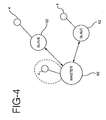
- FIG. 4 is a pictorial representation of a master-slave arrangement of controllers.
- the master controller unit 60 is located at a first area on the patient's skin.
- the slave units 62 are located at other areas on the patient's skin.
- Each of the slave units 62 has an iontophoretic patch 4 for delivering drugs to the patient. While FIG. 4 depicts one master unit and two slave units, any number of slave units can be used.
- a patch 4 controlled directly by the master controller 60 may also optionally be included.
- the master unit transmits commands to one or more of the slave units instructing the slave units to deliver drugs and, optionally, to control the drug dosage by controlling the amount of current to be generated by the slave units.
- the slave units have the capability of transmitting information back to the master unit, and the master unit has the capability of receiving this information.
- the embodiment can advantageously respond to changing conditions of the patient's body. For example, if an additional slave unit is affixed to the skin of the patient, the master unit 60 can recognize this condition, and instruct the slave unit to deliver drugs according to a desired pattern. Alternatively, if a slave unit 62 is removed from the patient's body, the master unit 60 can recognize this condition and adjust the operation of the remaining slave units accordingly.
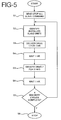
- FIGS. 5 and 6 show the operation of a master and slave arrangement configuration for alternately delivering two drugs to a patient. This configuration uses one master unit and two slave units.
- FIG. 5 depicts the operation of the master unit or controller in the master-slave configuration.
- the master unit After the master unit is turned on, it sends a stop command that stops all the slaves from delivering drugs in step S1.
- the master unit interrogates all of the slave units to identify which slave units are attached to the body.
- the master unit identifies a first controller for delivering a first drug and a second controller for delivering a second drug. Further, in this example, the first drug is delivered for one hour, followed by a one hour period during which no drug is delivered. Then, the second drug is delivered for three hours, followed by another hour during which no drug is delivered. This cycle is to be repeated four times, and then drug delivery is stopped.
- the master unit After the initializing steps S1 and S2, the master unit starts the desired sequence of drug delivery in step S3 by sending a command to the first slave unit to start delivering drugs. The master unit then keeps track of time until one hour has passed, at which time it sends a command to the first slave unit instructing it to stop delivering drugs.
- step S4 the master unit keeps track of time until one hour has passed.
- step S5 the master unit commands the second slave unit to start delivering its drug. The master unit keeps track of time until three hours have passed, at which time it sends a command to stop the second slave unit.
- step S6 the master unit waits for one hour to pass with no drug delivery. This completes a full cycle of drug delivery.
- the master unit keeps track of the number of cycles of drug delivery that have been completed.
- step S7 the master unit determines whether four drug delivery cycles have been completed. If four delivery cycles have not been completed, the master unit returns to the beginning of the routine for another cycle of drug delivery. When this cycle is complete, control returns to step S7. This continues until the master unit determines, in step S7, that four drug delivery cycles have been completed. When four delivery cycles have been completed, the master unit stops in step S8 and no further delivery of drugs occurs.
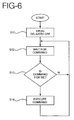
- FIG. 6 depicts the control sequence of the slave unit in the master-slave configuration.
- the slave unit When the slave unit is first turned on or otherwise activated, it turns off the delivery of drugs in step S11, and then proceeds to step S12 to wait for a command to arrive from the master unit.
- Some commands may be intended for the slave unit in question and other commands may be intended for other slave units.
- the slave unit examines the command in step S13 and determines if the command is intended for itself. If the command is not intended for that particular slave unit in S13, the slave unit will not execute the command and will return to step S12 to wait for another command. If it is determined, however, that the command is intended for the particular slave unit in step S13, the slave unit executes the received command in step S14.
- the command from the master unit may simply instruct the slave unit to start or stop delivering drugs, with the dosage being preset for a given slave unit.
- the command from the master unit may contain information for setting the slave unit to deliver a desired dosage of drugs by appropriately setting the level of DC current.
- the slave unit may also be programmed to acknowledge certain commands received from the master unit.
- the slave unit receives this type of command, it transmits an acknowledgment signal back to the master unit.
- This acknowledgment signal could be a simple present/absent indication. Alternatively, it could report the status of the slave unit, including, for example, the amount of drugs remaining in the slave unit, the status of the slave unit battery, and other parameters.
- FIG. 7 depicts a multi-master configuration of units or controllers. While FIG. 7 depicts two controllers 60, any number of controllers may be used. Each controller 60 has an associated patch 4 for delivery drugs to the patient. This configuration will be described in the context of delivering the same drug from multiple controllers, where the dosage of the drug is to be maintained constant regardless of the number of patches installed on the patient's body. In this configuration, when one patch is installed on the patient's body the dosage from each patch should be an amount "X"; when two patches are installed, the dosage from each patch should be X divided by 2; when three patches are installed, the dosage from each patch should be X divided by 3, and so on.
- This configuration could be used, for example, when a particular drug must be delivered constantly and where the dosage must be controlled with high accuracy. If a single controller were to be used in this application, a failure in that controller could interrupt the delivery of the drug. If independent controllers were used instead, a failure in any one controller might result in an incorrect drug dosage. By using a plurality of identical controllers that communicate with one another, these drawbacks can be eliminated and the desired drug dosage can be delivered.
- each of the multi-master units or controllers is programmed to adjust its drug output depending on how many other controllers are delivering drugs.
- a given controller When a given controller is first turned on, it stops the delivery of drugs in step S20.
- the controller sends and receives signals through the patient's body to determine a number of controllers (N) that are already delivering drugs to the patient.
- the controller sets its dosage to the desired total dosage (D) divided by N+1.
- the other controllers in the system will recognize that the new controller has been added when they execute their own step S21, and reduce their dosage from D ⁇ N to D ⁇ (N+1) in step S22.
- the final result is N+1 controllers each delivering a dosage of D ⁇ (N+1), resulting in a total dosage of D.
- the invention may take forms other than those specifically described.
- the signal may be capacitively coupled into the patients' skin.
- the master and slave units may be interconnected by wires and the like.
- the master is a transmit-only device and each of the slaves is a receive-only device.
- the demodulator 45 is not required in the master unit, and the modulator 43 is not required in each of the slave units.
Abstract
Description
Claims (10)
- An apparatus for delivering drugs to a patient, comprising:a master controller including a transmitter for transmitting, into a first area of skin of the patient, commands that travel along the patient's skin to a second area of skin of the patient, said master controller being affixable to the first area of skin; andat lease one slave unit including a slave controller and a slave drug delivery device,said slave unit being affixable to the second area of skin,said slave controller including a receiver capable of receiving the commands and an output signal connected to said slave drug delivery device, the output signal controlled in accordance with the received commands, andsaid slave drug delivery device delivering a drug in accordance with the output signal.
- The apparatus according to claim 1, whereinthe transmitter of said master controller comprises a modulator for modulating an AC carrier with commands to be transmitted,the slave drug delivery device of said slave unit comprises an iontophoretic patch,the slave controller causes the patch to deliver drugs to the patient by passing a DC current through the patch, andthe receiver of said slave unit comprises a demodulator for extracting the commands from the modulated carrier.
- An apparatus for delivering drugs to a patient, comprising:a first unit including a first drug delivery device and a first controller for causing the first drug delivery device to deliver a first drug, said first unit being affixable to a first area on the patient's skin; anda second unit including a second drug delivery device and a second controller for causing the second drug delivery device to deliver a second drug, said second unit being affixable to a second area on the patient's skin, said second controller selectively communicating with said first controller via signals that travel between said first controller and said second controller.
- The apparatus according to claim 3, whereineach controller includes a transmitter for transmitting signals, the transmitter comprising a modulator for modulating an AC carrier with commands to be transmitted, each controller includes a receiver for receiving signals, the receiver comprising a demodulator for extracting the commands from the modulated carrier, andeach drug delivery device comprises an iontophoretic patch.
- The apparatus according to claim 2 or claim 4, wherein the commands are coupled into the patient by a means selected from (a) superposing the modulated AC carrier with the DC current passing through the patch, and (b) capacitively coupling the modulated AC carrier into the patient's skin.
- The apparatus according to claim 2 or claim 4, wherein the frequency of the AC carrier is in a range selected from (a) radio frequency or lower, and (b) greater than about 1000 Hz.
- The apparatus according to claim 4, wherein the signal is conducted along the patient's skin.
- The apparatus according to claim 4, further comprising a third unit including a third drug delivery device and a third controller for causing the third drug delivery device to deliver a third drug, said third unit being affixable to a third area on the patient's skin, said third controller selectively communicating with said first controller and said second controller via signals that travel between said controllers.
- A method of delivering drugs to a patient from multiple sites on the patient's body, comprising the steps of:affixing a first drug delivery unit and a first controller to a first area of the patient's skin;affixing a second drug delivery unit and a second controller to a second area of the patient's skin;transmitting first information from the first controller to the second controller;receiving the first information at the second controller;controlling a delivery of drugs from the first drug delivery unit in accordance with the first information; andcontrolling a delivery of drugs from the second drug delivery unit in accordance with the first information.
- The method according to claim 9, further comprising the steps of:transmitting second information from the second controller to the first controller;receiving the second information at the first controller;controlling a delivery of drugs from the first drug delivery unit in accordance with the second information.
Applications Claiming Priority (2)
| Application Number | Priority Date | Filing Date | Title |
|---|---|---|---|
| US921915 | 1986-10-20 | ||
| US08/921,915 US5899876A (en) | 1997-08-27 | 1997-08-27 | Multiple site drug delivery system |
Publications (3)
| Publication Number | Publication Date |
|---|---|
| EP0906767A2 true EP0906767A2 (en) | 1999-04-07 |
| EP0906767A3 EP0906767A3 (en) | 2000-01-05 |
| EP0906767B1 EP0906767B1 (en) | 2005-03-30 |
Family
ID=25446177
Family Applications (1)
| Application Number | Title | Priority Date | Filing Date |
|---|---|---|---|
| EP98306884A Expired - Lifetime EP0906767B1 (en) | 1997-08-27 | 1998-08-27 | Multiple site drug delivery system |
Country Status (3)
| Country | Link |
|---|---|
| US (1) | US5899876A (en) |
| EP (1) | EP0906767B1 (en) |
| DE (1) | DE69829533T2 (en) |
Cited By (2)
| Publication number | Priority date | Publication date | Assignee | Title |
|---|---|---|---|---|
| EP1402920A1 (en) * | 2002-09-30 | 2004-03-31 | Faco S.A. | Device for electrical treatment of body especially electrostimulation or iontophoretic device |
| WO2006122903A1 (en) * | 2005-05-14 | 2006-11-23 | B. Braun Melsungen Ag | Method and device for controlling several infusion pumps |
Families Citing this family (102)
| Publication number | Priority date | Publication date | Assignee | Title |
|---|---|---|---|---|
| US6956032B1 (en) * | 1986-04-18 | 2005-10-18 | Carnegie Mellon University | Cyanine dyes as labeling reagents for detection of biological and other materials by luminescence methods |
| US6148231A (en) * | 1998-09-15 | 2000-11-14 | Biophoretic Therapeutic Systems, Llc | Iontophoretic drug delivery electrodes and method |
| US6792306B2 (en) * | 2000-03-10 | 2004-09-14 | Biophoretic Therapeutic Systems, Llc | Finger-mounted electrokinetic delivery system for self-administration of medicaments and methods therefor |
| US6477410B1 (en) * | 2000-05-31 | 2002-11-05 | Biophoretic Therapeutic Systems, Llc | Electrokinetic delivery of medicaments |
| US6553253B1 (en) * | 1999-03-12 | 2003-04-22 | Biophoretic Therapeutic Systems, Llc | Method and system for electrokinetic delivery of a substance |
| US7127285B2 (en) * | 1999-03-12 | 2006-10-24 | Transport Pharmaceuticals Inc. | Systems and methods for electrokinetic delivery of a substance |
| US6385488B1 (en) * | 1999-05-20 | 2002-05-07 | Vyteris, Inc. | Circuits for increasing the reliability of an iontophoretic system |
| US6835184B1 (en) | 1999-09-24 | 2004-12-28 | Becton, Dickinson And Company | Method and device for abrading skin |
| CA2400325A1 (en) | 2000-02-18 | 2001-08-23 | University Of Utah Research Foundation | Methods for delivering agents using alternating current |
| WO2001060448A1 (en) | 2000-02-18 | 2001-08-23 | University Of Utah Research Foundation | Methods for extracting substances using alternating current |
| US7137975B2 (en) * | 2001-02-13 | 2006-11-21 | Aciont, Inc. | Method for increasing the battery life of an alternating current iontophoresis device using a barrier-modifying agent |
| US7160258B2 (en) * | 2001-06-26 | 2007-01-09 | Entrack, Inc. | Capsule and method for treating or diagnosing the intestinal tract |
| US8391990B2 (en) | 2005-05-18 | 2013-03-05 | Cardiac Pacemakers, Inc. | Modular antitachyarrhythmia therapy system |
| JP5579445B2 (en) | 2007-01-22 | 2014-08-27 | オルソトロフィックス インコーポレイテッド | Peptide compositions and methods for promoting cartilage formation |
| US8197844B2 (en) | 2007-06-08 | 2012-06-12 | Activatek, Inc. | Active electrode for transdermal medicament administration |
| US8862223B2 (en) | 2008-01-18 | 2014-10-14 | Activatek, Inc. | Active transdermal medicament patch and circuit board for same |
| US20090259176A1 (en) * | 2008-04-09 | 2009-10-15 | Los Gatos Research, Inc. | Transdermal patch system |
| EP2310507A4 (en) | 2008-07-08 | 2013-03-20 | David Gladstone Inst | Methods and compositions for modulating angiogenesis |
| JP6038194B2 (en) * | 2013-02-18 | 2016-12-07 | テルモ株式会社 | Drug administration device, drug administration system, and operation method thereof |
| ES2661718T3 (en) | 2014-01-10 | 2018-04-03 | Cardiac Pacemakers, Inc. | Methods and systems to improve communication between medical devices |
| EP3092034B1 (en) | 2014-01-10 | 2019-10-30 | Cardiac Pacemakers, Inc. | Systems for detecting cardiac arrhythmias |
| US9757570B2 (en) | 2014-08-06 | 2017-09-12 | Cardiac Pacemakers, Inc. | Communications in a medical device system |
| US9808631B2 (en) | 2014-08-06 | 2017-11-07 | Cardiac Pacemakers, Inc. | Communication between a plurality of medical devices using time delays between communication pulses to distinguish between symbols |
| US9694189B2 (en) | 2014-08-06 | 2017-07-04 | Cardiac Pacemakers, Inc. | Method and apparatus for communicating between medical devices |
| US9526909B2 (en) | 2014-08-28 | 2016-12-27 | Cardiac Pacemakers, Inc. | Medical device with triggered blanking period |
| EP3827877A1 (en) | 2015-02-06 | 2021-06-02 | Cardiac Pacemakers, Inc. | Systems for treating cardiac arrhythmias |
| EP3253449B1 (en) | 2015-02-06 | 2018-12-12 | Cardiac Pacemakers, Inc. | Systems for safe delivery of electrical stimulation therapy |
| US10046167B2 (en) | 2015-02-09 | 2018-08-14 | Cardiac Pacemakers, Inc. | Implantable medical device with radiopaque ID tag |
| WO2016141046A1 (en) | 2015-03-04 | 2016-09-09 | Cardiac Pacemakers, Inc. | Systems and methods for treating cardiac arrhythmias |
| WO2016149262A1 (en) | 2015-03-18 | 2016-09-22 | Cardiac Pacemakers, Inc. | Communications in a medical device system with link quality assessment |
| US10050700B2 (en) | 2015-03-18 | 2018-08-14 | Cardiac Pacemakers, Inc. | Communications in a medical device system with temporal optimization |
| CN108136186B (en) | 2015-08-20 | 2021-09-17 | 心脏起搏器股份公司 | System and method for communication between medical devices |
| US10357159B2 (en) | 2015-08-20 | 2019-07-23 | Cardiac Pacemakers, Inc | Systems and methods for communication between medical devices |
| US9956414B2 (en) | 2015-08-27 | 2018-05-01 | Cardiac Pacemakers, Inc. | Temporal configuration of a motion sensor in an implantable medical device |
| US9968787B2 (en) | 2015-08-27 | 2018-05-15 | Cardiac Pacemakers, Inc. | Spatial configuration of a motion sensor in an implantable medical device |
| US10137305B2 (en) | 2015-08-28 | 2018-11-27 | Cardiac Pacemakers, Inc. | Systems and methods for behaviorally responsive signal detection and therapy delivery |
| US10159842B2 (en) | 2015-08-28 | 2018-12-25 | Cardiac Pacemakers, Inc. | System and method for detecting tamponade |
| US10226631B2 (en) | 2015-08-28 | 2019-03-12 | Cardiac Pacemakers, Inc. | Systems and methods for infarct detection |
| WO2017044389A1 (en) | 2015-09-11 | 2017-03-16 | Cardiac Pacemakers, Inc. | Arrhythmia detection and confirmation |
| US10065041B2 (en) | 2015-10-08 | 2018-09-04 | Cardiac Pacemakers, Inc. | Devices and methods for adjusting pacing rates in an implantable medical device |
| US10183170B2 (en) | 2015-12-17 | 2019-01-22 | Cardiac Pacemakers, Inc. | Conducted communication in a medical device system |
| US10905886B2 (en) | 2015-12-28 | 2021-02-02 | Cardiac Pacemakers, Inc. | Implantable medical device for deployment across the atrioventricular septum |
| WO2017127548A1 (en) | 2016-01-19 | 2017-07-27 | Cardiac Pacemakers, Inc. | Devices for wirelessly recharging a rechargeable battery of an implantable medical device |
| US10350423B2 (en) | 2016-02-04 | 2019-07-16 | Cardiac Pacemakers, Inc. | Delivery system with force sensor for leadless cardiac device |
| CN108883286B (en) | 2016-03-31 | 2021-12-07 | 心脏起搏器股份公司 | Implantable medical device with rechargeable battery |
| US10668294B2 (en) | 2016-05-10 | 2020-06-02 | Cardiac Pacemakers, Inc. | Leadless cardiac pacemaker configured for over the wire delivery |
| US10328272B2 (en) | 2016-05-10 | 2019-06-25 | Cardiac Pacemakers, Inc. | Retrievability for implantable medical devices |
| CN109414582B (en) | 2016-06-27 | 2022-10-28 | 心脏起搏器股份公司 | Cardiac therapy system for resynchronization pacing management using subcutaneous sensing of P-waves |
| WO2018009569A1 (en) | 2016-07-06 | 2018-01-11 | Cardiac Pacemakers, Inc. | Method and system for determining an atrial contraction timing fiducial in a leadless cardiac pacemaker system |
| US10426962B2 (en) | 2016-07-07 | 2019-10-01 | Cardiac Pacemakers, Inc. | Leadless pacemaker using pressure measurements for pacing capture verification |
| US10688304B2 (en) | 2016-07-20 | 2020-06-23 | Cardiac Pacemakers, Inc. | Method and system for utilizing an atrial contraction timing fiducial in a leadless cardiac pacemaker system |
| US10391319B2 (en) | 2016-08-19 | 2019-08-27 | Cardiac Pacemakers, Inc. | Trans septal implantable medical device |
| US10780278B2 (en) | 2016-08-24 | 2020-09-22 | Cardiac Pacemakers, Inc. | Integrated multi-device cardiac resynchronization therapy using P-wave to pace timing |
| US10870008B2 (en) | 2016-08-24 | 2020-12-22 | Cardiac Pacemakers, Inc. | Cardiac resynchronization using fusion promotion for timing management |
| US10758737B2 (en) | 2016-09-21 | 2020-09-01 | Cardiac Pacemakers, Inc. | Using sensor data from an intracardially implanted medical device to influence operation of an extracardially implantable cardioverter |
| US10994145B2 (en) | 2016-09-21 | 2021-05-04 | Cardiac Pacemakers, Inc. | Implantable cardiac monitor |
| EP3515553B1 (en) | 2016-09-21 | 2020-08-26 | Cardiac Pacemakers, Inc. | Leadless stimulation device with a housing that houses internal components of the leadless stimulation device and functions as the battery case and a terminal of an internal battery |
| JP7038115B2 (en) | 2016-10-27 | 2022-03-17 | カーディアック ペースメイカーズ, インコーポレイテッド | Implantable medical device with pressure sensor |
| US10561330B2 (en) | 2016-10-27 | 2020-02-18 | Cardiac Pacemakers, Inc. | Implantable medical device having a sense channel with performance adjustment |
| US10758724B2 (en) | 2016-10-27 | 2020-09-01 | Cardiac Pacemakers, Inc. | Implantable medical device delivery system with integrated sensor |
| WO2018081275A1 (en) | 2016-10-27 | 2018-05-03 | Cardiac Pacemakers, Inc. | Multi-device cardiac resynchronization therapy with timing enhancements |
| WO2018081237A1 (en) | 2016-10-27 | 2018-05-03 | Cardiac Pacemakers, Inc. | Use of a separate device in managing the pace pulse energy of a cardiac pacemaker |
| US10413733B2 (en) | 2016-10-27 | 2019-09-17 | Cardiac Pacemakers, Inc. | Implantable medical device with gyroscope |
| CN109890456B (en) | 2016-10-31 | 2023-06-13 | 心脏起搏器股份公司 | System for activity level pacing |
| WO2018081721A1 (en) | 2016-10-31 | 2018-05-03 | Cardiac Pacemakers, Inc | Systems for activity level pacing |
| WO2018089311A1 (en) | 2016-11-08 | 2018-05-17 | Cardiac Pacemakers, Inc | Implantable medical device for atrial deployment |
| EP3538213B1 (en) | 2016-11-09 | 2023-04-12 | Cardiac Pacemakers, Inc. | Systems and devices for setting cardiac pacing pulse parameters for a cardiac pacing device |
| WO2018093605A1 (en) | 2016-11-21 | 2018-05-24 | Cardiac Pacemakers, Inc. | Leadless cardiac pacemaker providing cardiac resynchronization therapy |
| US11147979B2 (en) | 2016-11-21 | 2021-10-19 | Cardiac Pacemakers, Inc. | Implantable medical device with a magnetically permeable housing and an inductive coil disposed about the housing |
| US10639486B2 (en) | 2016-11-21 | 2020-05-05 | Cardiac Pacemakers, Inc. | Implantable medical device with recharge coil |
| CN109963618B (en) | 2016-11-21 | 2023-07-04 | 心脏起搏器股份公司 | Leadless cardiac pacemaker with multi-mode communication |
| US10881869B2 (en) | 2016-11-21 | 2021-01-05 | Cardiac Pacemakers, Inc. | Wireless re-charge of an implantable medical device |
| US11207532B2 (en) | 2017-01-04 | 2021-12-28 | Cardiac Pacemakers, Inc. | Dynamic sensing updates using postural input in a multiple device cardiac rhythm management system |
| WO2018140623A1 (en) | 2017-01-26 | 2018-08-02 | Cardiac Pacemakers, Inc. | Leadless device with overmolded components |
| EP3573706A1 (en) | 2017-01-26 | 2019-12-04 | Cardiac Pacemakers, Inc. | Intra-body device communication with redundant message transmission |
| US10737102B2 (en) | 2017-01-26 | 2020-08-11 | Cardiac Pacemakers, Inc. | Leadless implantable device with detachable fixation |
| US10905872B2 (en) | 2017-04-03 | 2021-02-02 | Cardiac Pacemakers, Inc. | Implantable medical device with a movable electrode biased toward an extended position |
| AU2018248361B2 (en) | 2017-04-03 | 2020-08-27 | Cardiac Pacemakers, Inc. | Cardiac pacemaker with pacing pulse energy adjustment based on sensed heart rate |
| WO2019036600A1 (en) | 2017-08-18 | 2019-02-21 | Cardiac Pacemakers, Inc. | Implantable medical device with pressure sensor |
| US10918875B2 (en) | 2017-08-18 | 2021-02-16 | Cardiac Pacemakers, Inc. | Implantable medical device with a flux concentrator and a receiving coil disposed about the flux concentrator |
| CN111107899B (en) | 2017-09-20 | 2024-04-02 | 心脏起搏器股份公司 | Implantable medical device with multiple modes of operation |
| US11185703B2 (en) | 2017-11-07 | 2021-11-30 | Cardiac Pacemakers, Inc. | Leadless cardiac pacemaker for bundle of his pacing |
| EP3717060B1 (en) | 2017-12-01 | 2022-10-05 | Cardiac Pacemakers, Inc. | Leadless cardiac pacemaker with reversionary behavior |
| CN111417433A (en) | 2017-12-01 | 2020-07-14 | 心脏起搏器股份公司 | Method and system for detecting atrial contraction timing reference during ventricular filling from a ventricular implanted leadless cardiac pacemaker |
| EP3717059A1 (en) | 2017-12-01 | 2020-10-07 | Cardiac Pacemakers, Inc. | Methods and systems for detecting atrial contraction timing fiducials within a search window from a ventricularly implanted leadless cardiac pacemaker |
| EP3717063B1 (en) | 2017-12-01 | 2023-12-27 | Cardiac Pacemakers, Inc. | Systems for detecting atrial contraction timing fiducials and determining a cardiac interval from a ventricularly implanted leadless cardiac pacemaker |
| US11529523B2 (en) | 2018-01-04 | 2022-12-20 | Cardiac Pacemakers, Inc. | Handheld bridge device for providing a communication bridge between an implanted medical device and a smartphone |
| CN111556773A (en) | 2018-01-04 | 2020-08-18 | 心脏起搏器股份公司 | Dual chamber pacing without beat-to-beat communication |
| CN111936046A (en) | 2018-03-23 | 2020-11-13 | 美敦力公司 | VFA cardiac therapy for tachycardia |
| WO2019183512A1 (en) | 2018-03-23 | 2019-09-26 | Medtronic, Inc. | Vfa cardiac resynchronization therapy |
| CN111886046A (en) | 2018-03-23 | 2020-11-03 | 美敦力公司 | AV-synchronized VFA cardiac therapy |
| EP3856331A1 (en) | 2018-09-26 | 2021-08-04 | Medtronic, Inc. | Capture in ventricle-from-atrium cardiac therapy |
| US11951313B2 (en) | 2018-11-17 | 2024-04-09 | Medtronic, Inc. | VFA delivery systems and methods |
| CN109464742A (en) * | 2018-12-29 | 2019-03-15 | 上海安翰医疗技术有限公司 | Gastrointestinal tract position-sensing switch and preparation method thereof and alimentary canal site-specific drug release capsule |
| US11679265B2 (en) | 2019-02-14 | 2023-06-20 | Medtronic, Inc. | Lead-in-lead systems and methods for cardiac therapy |
| US11697025B2 (en) | 2019-03-29 | 2023-07-11 | Medtronic, Inc. | Cardiac conduction system capture |
| US11213676B2 (en) | 2019-04-01 | 2022-01-04 | Medtronic, Inc. | Delivery systems for VfA cardiac therapy |
| US11712188B2 (en) | 2019-05-07 | 2023-08-01 | Medtronic, Inc. | Posterior left bundle branch engagement |
| US11305127B2 (en) | 2019-08-26 | 2022-04-19 | Medtronic Inc. | VfA delivery and implant region detection |
| US11813466B2 (en) | 2020-01-27 | 2023-11-14 | Medtronic, Inc. | Atrioventricular nodal stimulation |
| US11911168B2 (en) | 2020-04-03 | 2024-02-27 | Medtronic, Inc. | Cardiac conduction system therapy benefit determination |
| US11813464B2 (en) | 2020-07-31 | 2023-11-14 | Medtronic, Inc. | Cardiac conduction system evaluation |
Family Cites Families (9)
| Publication number | Priority date | Publication date | Assignee | Title |
|---|---|---|---|---|
| US4856188A (en) * | 1984-10-12 | 1989-08-15 | Drug Delivery Systems Inc. | Method for making disposable and/or replenishable transdermal drug applicators |
| DE3831809A1 (en) * | 1988-09-19 | 1990-03-22 | Funke Hermann | DEVICE DETERMINED AT LEAST PARTLY IN THE LIVING BODY |
| ES2129035T3 (en) * | 1989-05-10 | 1999-06-01 | Drug Delivery Systems Inc | ELECTRIC TRANSDERMAL MEDICINE APPLICATOR WITH MULTIPLE SIGNALS. |
| US5135478A (en) * | 1989-05-10 | 1992-08-04 | Drug Delivery Systems Inc. | Multi-signal electrical transdermal drug applicator |
| IT1244030B (en) * | 1989-12-21 | 1994-06-28 | Elan Corp Plc | TWO-PART DEVICE FOR THE CONTROLLED ADMINISTRATION OF AN INGREDIENT |
| WO1991015261A1 (en) * | 1990-03-30 | 1991-10-17 | Medtronic, Inc. | Activity controlled electrotransport drug delivery device |
| US5254081A (en) * | 1991-02-01 | 1993-10-19 | Empi, Inc. | Multiple site drug iontophoresis electronic device and method |
| US5421817A (en) * | 1991-05-21 | 1995-06-06 | E.P., Inc. | Non-intrusive analgesic neuroaugmentive and iontophoretic delivery apparatus and management system |
| US5551953A (en) * | 1994-10-31 | 1996-09-03 | Alza Corporation | Electrotransport system with remote telemetry link |
-
1997
- 1997-08-27 US US08/921,915 patent/US5899876A/en not_active Expired - Fee Related
-
1998
- 1998-08-27 EP EP98306884A patent/EP0906767B1/en not_active Expired - Lifetime
- 1998-08-27 DE DE69829533T patent/DE69829533T2/en not_active Expired - Fee Related
Non-Patent Citations (1)
| Title |
|---|
| None |
Cited By (7)
| Publication number | Priority date | Publication date | Assignee | Title |
|---|---|---|---|---|
| EP1402920A1 (en) * | 2002-09-30 | 2004-03-31 | Faco S.A. | Device for electrical treatment of body especially electrostimulation or iontophoretic device |
| WO2004028625A1 (en) * | 2002-09-30 | 2004-04-08 | Faco S.A. | Device for body treatment by electrostimulation or iontophoresis |
| WO2006122903A1 (en) * | 2005-05-14 | 2006-11-23 | B. Braun Melsungen Ag | Method and device for controlling several infusion pumps |
| JP2008540004A (en) * | 2005-05-14 | 2008-11-20 | ベー・ブラウン・メルズンゲン・アクチエンゲゼルシャフト | Method and apparatus for controlling a plurality of infusion pumps |
| US8388598B2 (en) | 2005-05-14 | 2013-03-05 | B. Bruan Medizinelektronik GmbH & Co. KG | Method and device for controlling several infusion pumps |
| JP2016187587A (en) * | 2005-05-14 | 2016-11-04 | ベー・ブラウン・メルズンゲン・アクチエンゲゼルシャフトB.Braun Melsungen Aktiengesellschaft | Method and device for controlling multiple infusion pumps |
| EP1881858B1 (en) | 2005-05-14 | 2020-09-23 | B. Braun Melsungen AG | Device for controlling several infusion pumps |
Also Published As
| Publication number | Publication date |
|---|---|
| DE69829533T2 (en) | 2006-03-30 |
| DE69829533D1 (en) | 2005-05-04 |
| US5899876A (en) | 1999-05-04 |
| EP0906767B1 (en) | 2005-03-30 |
| EP0906767A3 (en) | 2000-01-05 |
Similar Documents
| Publication | Publication Date | Title |
|---|---|---|
| US5899876A (en) | Multiple site drug delivery system | |
| EP3740278B1 (en) | Electrical stimulation apparatus | |
| US6317630B1 (en) | Drug delivery device | |
| JP3916660B2 (en) | Electronic conveyor power saving device with reusable controller | |
| US6381496B1 (en) | Parameter context switching for an implanted device | |
| US6516227B1 (en) | Rechargeable spinal cord stimulator system | |
| EP2002861B1 (en) | Rechargeable stimulator system | |
| US20070060975A1 (en) | Combination electrode-battery and programming assembly for a miniature wireless transcutaneous electrical neuro or muscular-stimulation unit | |
| US4690144A (en) | Wireless transcutaneous electrical tissue stimulator | |
| US5830175A (en) | Iontophoretic drug delivery system, including disposable patch | |
| KR100376723B1 (en) | Electric transport transmission device | |
| US20020193844A1 (en) | Combination electrode-battery assembly for a miniature wireless transcutaneous electrical neuro or muscular-stimulation unit | |
| EP1302218A2 (en) | Awakenable iontrophoretic delivery device for reducing electrical sensation upon application thereof | |
| AU2000263762A1 (en) | Rechargeable spinal cord stimulator system | |
| JP2000507472A (en) | Electric carrier chemical delivery device with tactile stimulus generator | |
| AU714537B2 (en) | Electrotransport device having reusable controller | |
| US5983133A (en) | Iontophoresis system with voltage step-up circuit | |
| WO1996010441A9 (en) | Iontophoretic drug delivery system, including disposable patch and reusable, removable controller |
Legal Events
| Date | Code | Title | Description |
|---|---|---|---|
| PUAI | Public reference made under article 153(3) epc to a published international application that has entered the european phase |
Free format text: ORIGINAL CODE: 0009012 |
|
| AK | Designated contracting states |
Kind code of ref document: A2 Designated state(s): DE FR GB |
|
| AX | Request for extension of the european patent |
Free format text: AL;LT;LV;MK;RO;SI |
|
| PUAL | Search report despatched |
Free format text: ORIGINAL CODE: 0009013 |
|
| AK | Designated contracting states |
Kind code of ref document: A3 Designated state(s): AT BE CH CY DE DK ES FI FR GB GR IE IT LI LU MC NL PT SE |
|
| AX | Request for extension of the european patent |
Free format text: AL;LT;LV;MK;RO;SI |
|
| 17P | Request for examination filed |
Effective date: 20000628 |
|
| AKX | Designation fees paid |
Free format text: DE FR GB |
|
| RAP1 | Party data changed (applicant data changed or rights of an application transferred) |
Owner name: VYTERIS, INC. |
|
| 17Q | First examination report despatched |
Effective date: 20030429 |
|
| GRAP | Despatch of communication of intention to grant a patent |
Free format text: ORIGINAL CODE: EPIDOSNIGR1 |
|
| GRAS | Grant fee paid |
Free format text: ORIGINAL CODE: EPIDOSNIGR3 |
|
| GRAA | (expected) grant |
Free format text: ORIGINAL CODE: 0009210 |
|
| GRAL | Information related to payment of fee for publishing/printing deleted |
Free format text: ORIGINAL CODE: EPIDOSDIGR3 |
|
| GRAS | Grant fee paid |
Free format text: ORIGINAL CODE: EPIDOSNIGR3 |
|
| AK | Designated contracting states |
Kind code of ref document: B1 Designated state(s): DE FR GB |
|
| REG | Reference to a national code |
Ref country code: GB Ref legal event code: FG4D |
|
| REF | Corresponds to: |
Ref document number: 69829533 Country of ref document: DE Date of ref document: 20050504 Kind code of ref document: P |
|
| PLBE | No opposition filed within time limit |
Free format text: ORIGINAL CODE: 0009261 |
|
| STAA | Information on the status of an ep patent application or granted ep patent |
Free format text: STATUS: NO OPPOSITION FILED WITHIN TIME LIMIT |
|
| ET | Fr: translation filed | ||
| 26N | No opposition filed |
Effective date: 20060102 |
|
| PGFP | Annual fee paid to national office [announced via postgrant information from national office to epo] |
Ref country code: GB Payment date: 20070830 Year of fee payment: 10 |
|
| PGFP | Annual fee paid to national office [announced via postgrant information from national office to epo] |
Ref country code: DE Payment date: 20071001 Year of fee payment: 10 |
|
| PGFP | Annual fee paid to national office [announced via postgrant information from national office to epo] |
Ref country code: FR Payment date: 20070817 Year of fee payment: 10 |
|
| GBPC | Gb: european patent ceased through non-payment of renewal fee |
Effective date: 20080827 |
|
| REG | Reference to a national code |
Ref country code: FR Ref legal event code: ST Effective date: 20090430 |
|
| PG25 | Lapsed in a contracting state [announced via postgrant information from national office to epo] |
Ref country code: FR Free format text: LAPSE BECAUSE OF NON-PAYMENT OF DUE FEES Effective date: 20080901 Ref country code: DE Free format text: LAPSE BECAUSE OF NON-PAYMENT OF DUE FEES Effective date: 20090303 |
|
| PG25 | Lapsed in a contracting state [announced via postgrant information from national office to epo] |
Ref country code: GB Free format text: LAPSE BECAUSE OF NON-PAYMENT OF DUE FEES Effective date: 20080827 |