EP0905657A1 - Currency note comprising an integrated circuit - Google Patents
Currency note comprising an integrated circuit Download PDFInfo
- Publication number
- EP0905657A1 EP0905657A1 EP97830464A EP97830464A EP0905657A1 EP 0905657 A1 EP0905657 A1 EP 0905657A1 EP 97830464 A EP97830464 A EP 97830464A EP 97830464 A EP97830464 A EP 97830464A EP 0905657 A1 EP0905657 A1 EP 0905657A1
- Authority
- EP
- European Patent Office
- Prior art keywords
- note
- integrated circuit
- terminals
- banknote
- antenna
- Prior art date
- Legal status (The legal status is an assumption and is not a legal conclusion. Google has not performed a legal analysis and makes no representation as to the accuracy of the status listed.)
- Granted
Links
Images

Classifications
-
- G—PHYSICS
- G06—COMPUTING; CALCULATING OR COUNTING
- G06K—GRAPHICAL DATA READING; PRESENTATION OF DATA; RECORD CARRIERS; HANDLING RECORD CARRIERS
- G06K19/00—Record carriers for use with machines and with at least a part designed to carry digital markings
- G06K19/06—Record carriers for use with machines and with at least a part designed to carry digital markings characterised by the kind of the digital marking, e.g. shape, nature, code
- G06K19/067—Record carriers with conductive marks, printed circuits or semiconductor circuit elements, e.g. credit or identity cards also with resonating or responding marks without active components
- G06K19/07—Record carriers with conductive marks, printed circuits or semiconductor circuit elements, e.g. credit or identity cards also with resonating or responding marks without active components with integrated circuit chips
- G06K19/077—Constructional details, e.g. mounting of circuits in the carrier
- G06K19/07749—Constructional details, e.g. mounting of circuits in the carrier the record carrier being capable of non-contact communication, e.g. constructional details of the antenna of a non-contact smart card
-
- G—PHYSICS
- G07—CHECKING-DEVICES
- G07D—HANDLING OF COINS OR VALUABLE PAPERS, e.g. TESTING, SORTING BY DENOMINATIONS, COUNTING, DISPENSING, CHANGING OR DEPOSITING
- G07D7/00—Testing specially adapted to determine the identity or genuineness of valuable papers or for segregating those which are unacceptable, e.g. banknotes that are alien to a currency
- G07D7/01—Testing electronic circuits therein
Definitions
- This invention relates to currency notes incorporating an identification and/or authentication element.
- the idea behind this invention is one of using, as an identifying and/or authenticating element, an integrated circuit applied to or embedded in the note.
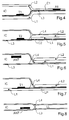
- FIGS 1, 2 and 3 show three different embodiments of a banknote BN according to the invention, which banknote incorporates an integrated circuit IC as its identifying and/or authenticating element.
- IC integrated circuit
- two or more integrated circuits could be interconnected within each banknote, although this choice would be less advantageous due to the difficulty of establishing a large number of electric connections within a banknote.
- the integrated circuit IC is to store information that can be read by a suitable authentication apparatus external of the banknote BN, in a similar manner to the aforementioned "Supertag" system and contact or contact-less smart cards.
- the items of information stored by the integrated circuit may be, for example, a real or par value, identity, date of issuance, and issuer of the note. This information may also appear in print on the note, more or less as in current practice. Based on such information, the note can be readily identified, even in an automatic manner.
- an integrated circuit capable of transmitting predetermined response signals in response to predetermined interrogation signals represents an effective authentication element.
- integrated circuits are no articles that can be fabricated at tyro level, and surely not at a low cost.
- the integrated circuit IC has no terminals, and includes an integrated antenna ANT, which may be a loop of a conductive material formed in the peripheral region of the integrated circuit.
- the word "terminals” means here areas of the integrated circuit which are prearranged for electrically connecting the integrated circuit to external electric and/or electronic circuits.
- the interrogation and response signals are RF signals
- the integrated circuit IC is to include suitable circuitry for receiving and transmitting them, and capable of self-feeding by RF power, similar to the integrated circuits of contact-less smart cards.
- the integrated circuit IC has two terminals T1 and T2, omitted from Figures 1 and 2. These terminals may be provided on one face or on opposite faces of the integrated circuit IC.
- Two terminals are a minimum for establishing between two electric systems a bi-directional transmission of informational signals and a one-way transmission of power.
- the integrated circuit IC may be provided with plural terminals; in general, this would bring about a simplification in the circuitry within the integrated circuit IC, but also a complication in the construction of the banknote BN.
- the banknote BN also includes an antenna which is connected to the terminals T1 and T2.
- the integrated circuit IC and/or the banknote BN could be provided with a receiving antenna and a transmitting antenna, although this would involve added complexity and cost.
- the antenna comprises two electric conductors C1 and C2 connected to the terminals T1 and T2, respectively, and embedded in the note. Accordingly, the antenna is an open dipole. This is similar to the arrangement provided in the "Supertag" system.
- the antenna consists of a loop LP formed from an electric conductor which has its two ends connected to the terminals T1 and T2 and is embedded in the note. Accordingly, this antenna is a closed dipole.
- the loop can also be said to form the secondary winding of an air-core transformer having its primary winding placed within the authentication apparatus. This is similar to the arrangement provided for contact-less smart cards.
- the banknote BN may additionally include two electric conductors C1 and C2 connected electrically to the terminals T1 and T2, and having two external contact pads A1 and A2, respectively. These pads may be on the same face or different faces of the banknote BN, and in the extreme, located at an edge thereof.
- the terminals T1 and T2 of the integrated circuit IC could be made accessible directly from outside the banknote BN for electric contacting, as in the embodiment of Figure 9.
- the terminals might locate on and be accessed from different sides of the banknote BN.
- the integrated circuit IC layout can be similar to that of a smart card "with contacts".
- the electric conductors C1, C2, LP can be formed in the banknote by any of several methods: they may be printed in conductive ink, be thin wires embedded in the note, or be very thin (e.g. 300 ⁇ thick) metal strips deposited onto thin (e.g. 10 ⁇ m thick) plastics strips embedded in the note.
- the cost of the security device i.e. the integrated circuit
- the cost of a fairly simple integrated circuit may amount to a half-dollar and, accordingly, it would seem reasonable to use the circuit for denominations upward of fifty dollars. Therefore, if the utilization of this invention is to be extended to include lower denominations, of primary consideration become: the use of inexpensive semiconductor manufacturing processes; an integrated circuit layout of small area, and hence simple circuitry, so that a semiconductor wafer can accommodate a large number of them; and the adoption of very large volume manufacturing methods.
- the thickness of the insert consisting of the integrated circuit should not exceed that of standard banknote paper.
- standard sheet paper for office use is 30 to 60 ⁇ m thick
- ply paper for banknote printing has a thickness of 50 to 100 ⁇ m
- thin opaque or transparent sheet plastics may range in thickness from 8 to 15 ⁇ m
- the thickness of an integrated circuit for smart cards is approximately 180 ⁇ m.
- a suitable thickness for the integrated circuit in this invention would be less than 100 ⁇ m, preferably less than 50 ⁇ m.
- CMP Chemical Mechanical Polishing
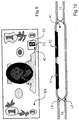
- banknote Some embodiments of a banknote according to the invention will now be described with the aid of sectional views thereof. These sectional views are taken at the locations of the integrated circuit IC, and of the conductors C1, C2, LP, where provided. The banknote construction obviously is simpler elsewhere.
- the banknote comprises a first sheet paper layer L1 and a second sheet paper layer L2 overlying the first. Sandwiched between these layers is the integrated circuit IC provided with (visible) T1 and (invisible) T2 terminals. Also sandwiched between the layers L1 and L2 are a thin plastics layer L3 and a very thin metal layer, deposited over the layer L3 that forms the conductor C1. The conductor C1 has a contact pad A1 which appears at the surface of the layer L2 and contacts the terminal T1.
- the banknote comprises first L1 and second L2 overlapping sheet paper layers, and first L3 and second L4 thin plastics layers which are apertured at the integrated circuit IC.
- a very thin metal layer is deposited onto the layer L3 and forms the conductor C2.
- the integrated circuit IC is sandwiched between the layers L3 and L4 and has (invisible) T1 and (visible) T2 terminals.
- Figure 5 could be, for example, a cross-section through the banknote BN of Figure 1.
- the banknote comprises first L3 and second L4 thin overlapping plastics layers, and first L1 and second L2 overlapping sheet paper layers.
- the layers L1 and L2 overlie the layers L3 and L4.
- the layers L1 and L2 are apertured at the integrated circuit IC.
- the integrated circuit IC is sandwiched between the layers L3 and L4, and provided with an integrated antenna ANT.
- Figure 6 could be, for example, a cross-section through the banknote BN of Figure 3.
- the banknote comprises first L1 and second L2 overlapping sheet paper layers, and a thin plastics layer L4 placed between the layers L1 and L2.
- the layer L2 is apertured at the integrated circuit IC.
- the integrated circuit IC is placed between the layers L1 and L4 and provided with (visible) T1 and (invisible) T2 terminals.
- Printed in conductive ink onto the layer L1 is a loop LP in contact with the terminals T1 and T2.
- Figure 7 could be, for example, a cross-section through the banknote BN of Figure 2.
- the banknote comprises a single sheet paper layer LL, and first L3 and second L4 thin plastics layers enclosing it.
- the layer LL is apertured at the integrated circuit IC.
- the integrated circuit IC is placed between the layers L3 and L4 and provided with an integrated antenna ANT.
- Figure 8 could be, for example, a cross-section through the banknote BN of Figure 3.
- the banknote comprises a single sheet paper layer LL, and first L3 and second L4 thin plastics layers enclosing it.
- the layer LL is apertured at the integrated circuit IC.
- the integrated circuit IC is placed between the layers L3 and L4 and provided with two terminals T1 and T2 which appear at the surface of the layer L4 and, therefore, can be accessed directly from outside the banknote BN for electric contact purposes.
- Figure 10 is a cross-section through the banknote BN of Figure 9.
- the integrated circuit IC is fully isolated from the note exterior.
- the integrated circuit IC should be provided with suitable passivation layers to protect and seal it at least from moisture.
- the information that can be stored in the integrated circuit IC is, for example, a real or par value, the identity, the issuer, and the date of issuance of the note.
- the integrated circuit IC may be adapted to store this and/or other elements of information in a crypted form, such as read and/or write passwords.
- the authentication operation corresponds to reading the information from the integrated circuit and checking it for correctness in an automatic or manual manner.
- the reading may be free or subordinate to the integrated circuit receiving a read password.
- the integrated circuit can be arranged for the integrated circuit to request a password before information can be written thereinto.
- the integrated circuit may be provided with a non-volatile memory which can be programmed only once, that is by an irreversible physical action.
- Such a memory could be selected from ROMs, PROMs, UPROMs or CAMs or fused memories, EPROMs without erase windows or EEPROMs without erase circuits, in decreasing order of security level. Another factor not to be overlooked is ease of programming. ROMs can only be factory programmed (so that each note must be provided with an individually different integrated circuit), while PROMs and EPROMs require high program voltages. The manufacturing cost of the integrated circuit is also a factor.
- An alternative choice would be to provide the integrated circuit with a non-volatile memory for storing identity information, and with a security circuit having a non-erasable (i.e. programmable only once) memory, such as a fused memory, and being effective to inhibit programming of the non-volatile memory in relation to the contents of the non-erasable memory.
- a non-erasable memory such as a fused memory
- the following procedure may be used.
- the integrated circuit receives a program command, it checks the non-erasable memory for its contents: if these contents reveal that the non-volatile memory has already been programmed, the program command is not executed; otherwise, the command is executed, and the contents of the non-erasable memory are set to prevent future re-programming. This safeguard against re-programming may be provided for segments rather than the whole memory.
- a second non-volatile memory could be provided additionally to a fully safeguarded non-volatile memory, e.g. for bank branch offices to record information in a banknote.
- the first memory might be of the fused type and the second memory be either safeguarded by means of a write password or be freely programmable.
- the non-erasable memory may be adapted to store a plurality of bits, each bit being associated with a different memory segment, and some of these bits having fixed informational contents to indicate that the segment is freely programmable, while other bits would have varying informational contents as previously explained.
Abstract

Description
Claims (17)
- A currency note (BN), characterized in that it includes at least one integrated circuit (IC) as its identification and/or authentication element.
- A note (BN) according to Claim 1, wherein the integrated circuit (IC) has an integrated antenna (ANT) and no terminals.
- A note (BN) according to Claim 1, wherein the integrated circuit (IC) has two or more terminals (T1,T2).
- A note (BN) according to Claim 1, wherein the integrated circuit (IC) thickness is less than 100µm, preferably less than 50µm.
- A note (BN) according to Claim 3, further including an antenna (C1,C2;LP) which is connected electrically to said terminals (T1,T2).
- A note (BN) according to Claim 5, wherein the antenna comprises two electric conductors (C1,C2) embedded in the note.
- A note (BN) according to Claim 5, wherein the antenna consists of a loop (LP) comprising an electric conductor embedded in the note.
- A note (BN) according to Claim 3, further including two electric conductors (C1,C2) connected electrically to said terminals and provided with two external contact pads (A1,A2), respectively.
- A note (BN) according to Claim 3, wherein said terminals (T1,T2) are accessible directly from outside the note for electric contacting purposes.
- A note (BN) according to Claim 1, wherein the integrated circuit (IC) is adapted to store information.
- A note (BN) according to Claim 10, wherein the integrated circuit (IC) is adapted to store information relating to the face value of the note.
- A note (BN) according to Claim 10, wherein the integrated circuit (IC) is adapted to store information relating to the identity of the note.
- A note (BN) according to Claim 10, wherein the integrated circuit (IC) is adapted to store information relating to the issuer of the note.
- A note (BN) according to Claim 10, wherein the integrated circuit (IC) is adapted to store information relating to the date of issuance of the note.
- A note (BN) according to Claim 10, wherein the integrated circuit (IC) is adapted to store different elements of information at different times.
- A note (BN) according to Claim 10, wherein the integrated circuit (IC) includes a non-volatile memory programmable only once.
- A note (BN) according to Claim 10, wherein the integrated circuit (IC) includes a non-volatile memory for storing said information, as well a security circuit provided with a non-erasable memory and adapted to inhibit the programming of said non-volatile memory in relation to the informational contents of said non-erasable memory.
Priority Applications (3)
| Application Number | Priority Date | Filing Date | Title |
|---|---|---|---|
| EP97830464A EP0905657B1 (en) | 1997-09-23 | 1997-09-23 | Currency note comprising an integrated circuit |
| DE69722403T DE69722403T2 (en) | 1997-09-23 | 1997-09-23 | Banknote with an integrated circuit |
| US09/645,008 US6547151B1 (en) | 1997-09-23 | 2000-08-23 | Currency note comprising an integrated circuit |
Applications Claiming Priority (1)
| Application Number | Priority Date | Filing Date | Title |
|---|---|---|---|
| EP97830464A EP0905657B1 (en) | 1997-09-23 | 1997-09-23 | Currency note comprising an integrated circuit |
Publications (2)
| Publication Number | Publication Date |
|---|---|
| EP0905657A1 true EP0905657A1 (en) | 1999-03-31 |
| EP0905657B1 EP0905657B1 (en) | 2003-05-28 |
Family
ID=8230779
Family Applications (1)
| Application Number | Title | Priority Date | Filing Date |
|---|---|---|---|
| EP97830464A Revoked EP0905657B1 (en) | 1997-09-23 | 1997-09-23 | Currency note comprising an integrated circuit |
Country Status (3)
| Country | Link |
|---|---|
| US (1) | US6547151B1 (en) |
| EP (1) | EP0905657B1 (en) |
| DE (1) | DE69722403T2 (en) |
Cited By (24)
| Publication number | Priority date | Publication date | Assignee | Title |
|---|---|---|---|---|
| DE19849762A1 (en) * | 1998-10-28 | 2000-05-04 | Joergen Brosow | Method of verifying the authenticity of security paper such as a banknote that uses an embedded electronic circuit that responds to an external interrogation signal |
| WO2000033418A1 (en) * | 1998-12-01 | 2000-06-08 | Infineon Technologies Ag | Bar antenna comprised of an electrically conductive plastic |
| NL1011860C2 (en) * | 1999-04-22 | 2000-10-24 | Vhp Ugchelen Bv | Safety device and applications thereof. |
| EP1101203A1 (en) † | 1998-07-27 | 2001-05-23 | Siemens Aktiengesellschaft | Security paper, method and device for checking the authenticity of documents recorded thereon |
| WO2001039137A1 (en) * | 1999-11-25 | 2001-05-31 | Infineon Technologies Ag | Flat support with at least one semiconductor chip |
| GB2357619A (en) * | 1999-12-24 | 2001-06-27 | Meshack Yaw Asare | Anti-robbery cash handling system |
| EP1179810A1 (en) * | 2000-08-11 | 2002-02-13 | European Central Bank, Directorate Banknotes, RDDO | Security documents data exchange system |
| WO2002050890A2 (en) * | 2000-12-21 | 2002-06-27 | Giesecke & Devrient Gmbh | Electroconductive connection between a chip and a coupling element in addition to a security element containing a connection of said type |
| WO2002054356A2 (en) * | 2001-01-02 | 2002-07-11 | Giesecke & Devrient Gmbh | Valuable document having an integrated circuit, method for checking authenticity and method for monitoring the quality of said valuable document |
| WO2003054807A2 (en) | 2001-12-21 | 2003-07-03 | Giesecke & Devrient Gmbh | Value document and device for processing value documents |
| WO2003054808A2 (en) * | 2001-12-21 | 2003-07-03 | Giesecke & Devrient Gmbh | Devices and methods for the production of sheet material |
| WO2003079299A2 (en) * | 2002-03-18 | 2003-09-25 | Koninklijke Philips Electronics N.V. | Holder for papers of value, and method of registering the contents thereof |
| WO2004056583A1 (en) | 2002-12-20 | 2004-07-08 | European Central Bank | Security document comprising electronic security means |
| WO2004084303A2 (en) * | 2003-03-18 | 2004-09-30 | Infineon Technologies Ag | Flip-chip arrangment on a substrate carrier |
| WO2004091929A1 (en) * | 2003-04-15 | 2004-10-28 | Giesecke & Devrient Gmbh | Value paper |
| EP1367547A3 (en) * | 2002-05-29 | 2005-10-05 | Hitachi, Ltd. | Bill handling machine |
| WO2006089439A1 (en) * | 2005-02-23 | 2006-08-31 | Textilma Ag | Transponder-thread and application thereof |
| WO2006119724A1 (en) * | 2005-05-12 | 2006-11-16 | Infineon Technologies Ag | Semiconductor chips for tag applications, devices for assembling the semiconductor chips and assembly method |
| WO2008014993A1 (en) | 2006-08-03 | 2008-02-07 | Giesecke & Devrient Gmbh | Security elements for aerials |
| DE10214369B4 (en) * | 2002-01-10 | 2010-06-17 | Bundesdruckerei Gmbh | Value or security document with Seebeck or Peltier element |
| US7847698B2 (en) | 2001-04-26 | 2010-12-07 | Arjowiggins Security SAS | Cover incorporating a radio frequency identification device |
| US7857012B2 (en) | 2005-10-06 | 2010-12-28 | Textilma Ag | Method and needle webbing loom in order to weave a ribbon |
| US7872579B2 (en) | 2004-04-14 | 2011-01-18 | Arjowiggins Security | Structure including an electronic device, in particular for fabricating a security document or a document of value |
| EP1525564B2 (en) † | 2002-07-17 | 2012-08-22 | Oesterreichische Banknoten- und Sicherheitsdruck GmbH | Method for producing a banknote |
Families Citing this family (40)
| Publication number | Priority date | Publication date | Assignee | Title |
|---|---|---|---|---|
| NL1008929C2 (en) * | 1998-04-20 | 1999-10-21 | Vhp Ugchelen Bv | Substrate made of paper provided with an integrated circuit. |
| WO2000034923A1 (en) * | 1998-12-07 | 2000-06-15 | Hitachi, Ltd. | Method of checking authenticity of sheet with built-in electronic circuit chip |
| DE10032128A1 (en) * | 2000-07-05 | 2002-01-17 | Giesecke & Devrient Gmbh | Security paper and value document made from it |
| US6851617B2 (en) * | 2002-04-19 | 2005-02-08 | Avery Dennison Corporation | Laser imageable RFID label/tag |
| US7221258B2 (en) * | 2002-11-23 | 2007-05-22 | Kathleen Lane | Hierarchical electronic watermarks and method of use |
| US7170391B2 (en) * | 2002-11-23 | 2007-01-30 | Kathleen Lane | Birth and other legal documents having an RFID device and method of use for certification and authentication |
| GB2397272B (en) * | 2003-01-15 | 2006-11-15 | Hewlett Packard Co | Secure physical documents and methods and apparatus for publishing and reading them |
| US7077332B2 (en) * | 2003-03-19 | 2006-07-18 | Translucent Technologies, Llc | Media verification system |
| DE10335230A1 (en) * | 2003-08-01 | 2005-02-17 | Man Roland Druckmaschinen Ag | Process for the production of RFID labels |
| DE10336566A1 (en) * | 2003-08-08 | 2005-02-24 | Giesecke & Devrient Gmbh | Banknote is produced with an integral electronic circuit and activator coupled to an antenna to transmit data |
| WO2005027032A1 (en) * | 2003-08-29 | 2005-03-24 | Translucent Technologies, Llc | Media verification system |
| US7792754B2 (en) * | 2003-10-22 | 2010-09-07 | Ncr Corporation | Financial document item processing system and method of operating a financial document item processing system to encode/endorse a financial document item having a radio frequency identification tag |
| GB0325734D0 (en) * | 2003-11-04 | 2003-12-10 | Fluiditi Ltd | Improved transport and delivery system for valuable items |
| JP4613013B2 (en) * | 2004-01-06 | 2011-01-12 | 日立オムロンターミナルソリューションズ株式会社 | Paper sheet handling device and paper sheet identification method |
| US20050156318A1 (en) * | 2004-01-15 | 2005-07-21 | Douglas Joel S. | Security marking and security mark |
| US7246754B2 (en) * | 2004-02-18 | 2007-07-24 | Hewlett-Packard Development Company, L.P. | Secure currency |
| EP1749273A4 (en) * | 2004-05-18 | 2011-12-28 | Silverbrook Res Pty Ltd | Authentication of an object using a signature encoded in a number of data portions |
| WO2006008700A1 (en) * | 2004-07-13 | 2006-01-26 | Koninklijke Philips Electronics N.V. | Security paper and articles comprising such paper |
| JP4528067B2 (en) * | 2004-09-02 | 2010-08-18 | 日立オムロンターミナルソリューションズ株式会社 | Bill handling device, bill management system, bill management method, and paper sheet handling device |
| US20060108056A1 (en) * | 2004-11-24 | 2006-05-25 | The Boeing Company | Method and apparatus for foreign object detection in a composite layer fabrication process |
| GB0426620D0 (en) * | 2004-12-03 | 2005-01-05 | Firstondemand Ltd | On-line generation and verification of personalised money |
| GB0426624D0 (en) * | 2004-12-03 | 2005-01-05 | Firstondemand Ltd | Prescription generation,validation and tracking |
| US20090293112A1 (en) * | 2004-12-03 | 2009-11-26 | Stephen James Moore | On-line generation and authentication of items |
| JP2006209497A (en) * | 2005-01-28 | 2006-08-10 | Seiko Epson Corp | Rfid tag, print sheet, printer device and rfid system |
| GB0503972D0 (en) * | 2005-02-25 | 2005-04-06 | Firstondemand Ltd | Identification systems |
| GB0504573D0 (en) * | 2005-03-04 | 2005-04-13 | Firstondemand Ltd | Traceability and authentication of security papers |
| JP2006256124A (en) * | 2005-03-17 | 2006-09-28 | Fuji Xerox Co Ltd | Magnetic wire applying device and method therefor |
| DE102005030289A1 (en) * | 2005-06-29 | 2007-07-05 | Giesecke & Devrient Gmbh | Apparatus and method for testing sensors |
| FR2907948B1 (en) * | 2006-10-25 | 2009-01-30 | Ingenico Sa | METHOD OF FIGHT AGAINST TICKET FLIGHT, TICKET, CORRESPONDING INACTIVATION DEVICE AND ACTIVATION DEVICE |
| CA2627004A1 (en) * | 2007-03-22 | 2008-09-22 | Photogram Technologies Inc. | Hand-held decoder card having a parallax barrier portion and a light filtering portion and method of making same |
| CA2741675A1 (en) * | 2008-10-23 | 2010-04-29 | Ocelot, Llc. | Data storage devices |
| US8523071B2 (en) * | 2009-10-22 | 2013-09-03 | Intellipaper, Llc | Electronic assemblies and methods of forming electronic assemblies |
| US8469280B2 (en) | 2009-10-22 | 2013-06-25 | Intellipaper, Llc | Programming devices and programming methods |
| US8469271B2 (en) | 2009-10-22 | 2013-06-25 | Intellipaper, Llc | Electronic storage devices, programming methods, and device manufacturing methods |
| WO2011127183A2 (en) | 2010-04-07 | 2011-10-13 | Intellipaper , Llc | Memomy programming methods and memory programming devices |
| TWI496255B (en) * | 2011-04-07 | 2015-08-11 | Intellipaper Llc | Electronic assemblies and methods of forming electronic assemblies |
| BR102013008962A2 (en) * | 2013-04-12 | 2014-11-25 | Antonio Ferreira De Souza | AUTHENTICITY CONSULTING, NEGATIVE (INVALIDATION OR RESTRICTION) CONSULTATION AND REVALIDATION, CONTROL, TRACKING AND INFORMATION CONCERNING MONETARY CELLS AND IMAGES (HARDWARE AND SOFTWARE EMBARTILATED TO APPLICATED TABLETS, APPLICATED LANDSCAPES, AND A LABELS TO PC) , PDA'S, FIXED AND MOBILE TERMINALS AND SMARTPHONES, WITH AUDIOVISUAL RETURN, VIA SMS AND / OR EMAIL |
| US11275979B2 (en) * | 2018-08-17 | 2022-03-15 | Olof Kyros Gustafsson | Note backed by cryptocurrency |
| DE102019131654B4 (en) | 2019-11-22 | 2022-03-17 | Koenig & Bauer Ag | Process for producing banknotes each having at least one integrated circuit |
| US20210342659A1 (en) * | 2020-05-01 | 2021-11-04 | X-Celeprint Limited | Hybrid documents with electronic indicia |
Citations (4)
| Publication number | Priority date | Publication date | Assignee | Title |
|---|---|---|---|---|
| EP0019191A1 (en) * | 1979-05-16 | 1980-11-26 | BROWN, BOVERI & CIE Aktiengesellschaft Mannheim | Security paper |
| US4472627A (en) * | 1982-09-30 | 1984-09-18 | The United States Of America As Represented By The Secretary Of The Treasury | Authenticating and anti-counterfeiting device for currency |
| US5537105A (en) * | 1991-01-04 | 1996-07-16 | British Technology Group Limited | Electronic identification system |
| US5566441A (en) * | 1993-03-11 | 1996-10-22 | British Technology Group Limited | Attaching an electronic circuit to a substrate |
Family Cites Families (14)
| Publication number | Priority date | Publication date | Assignee | Title |
|---|---|---|---|---|
| DE2925273C2 (en) | 1979-06-22 | 1981-09-17 | GAO Gesellschaft für Automation und Organisation mbH, 8000 München | Security with a security thread |
| DE3421041A1 (en) * | 1984-06-06 | 1985-12-12 | GAO Gesellschaft für Automation und Organisation mbH, 8000 München | SECURITY DOCUMENTS AND METHOD FOR TESTING THE SAME |
| US4783646A (en) | 1986-03-07 | 1988-11-08 | Kabushiki Kaisha Toshiba | Stolen article detection tag sheet, and method for manufacturing the same |
| US5341428A (en) * | 1992-01-30 | 1994-08-23 | Gbs Systems Corporation | Multiple cross-check document verification system |
| US5545885A (en) | 1992-06-01 | 1996-08-13 | Eastman Kodak Company | Method and apparatus for detecting and identifying coded magnetic patterns on genuine articles such as bank notes |
| DE9422424U1 (en) | 1994-02-04 | 2002-02-21 | Giesecke & Devrient Gmbh | Chip card with an electronic module |
| DE4416697A1 (en) | 1994-05-11 | 1995-11-16 | Giesecke & Devrient Gmbh | Data carrier with integrated circuit |
| DE4419805A1 (en) * | 1994-06-06 | 1995-12-07 | Giesecke & Devrient Gmbh | Method for checking the authenticity of a data carrier |
| JPH10511488A (en) * | 1995-10-19 | 1998-11-04 | フィリップス エレクトロニクス ネムローゼ フェンノートシャップ | Conductor means in a token external to the circuit for realizing the identifier token and the identifier code having an electronic circuit |
| US6111506A (en) * | 1996-10-15 | 2000-08-29 | Iris Corporation Berhad | Method of making an improved security identification document including contactless communication insert unit |
| US5828753A (en) * | 1996-10-25 | 1998-10-27 | Intel Corporation | Circuit and method for ensuring interconnect security within a multi-chip integrated circuit package |
| US5984190A (en) * | 1997-05-15 | 1999-11-16 | Micron Technology, Inc. | Method and apparatus for identifying integrated circuits |
| US6050494A (en) * | 1997-06-09 | 2000-04-18 | Samsung Display Devices Co., Ltd. | Smart card |
| JP2000353206A (en) * | 1999-06-11 | 2000-12-19 | Lsi Japan Kk | Electronic currency and its system |
-
1997
- 1997-09-23 EP EP97830464A patent/EP0905657B1/en not_active Revoked
- 1997-09-23 DE DE69722403T patent/DE69722403T2/en not_active Revoked
-
2000
- 2000-08-23 US US09/645,008 patent/US6547151B1/en not_active Expired - Lifetime
Patent Citations (4)
| Publication number | Priority date | Publication date | Assignee | Title |
|---|---|---|---|---|
| EP0019191A1 (en) * | 1979-05-16 | 1980-11-26 | BROWN, BOVERI & CIE Aktiengesellschaft Mannheim | Security paper |
| US4472627A (en) * | 1982-09-30 | 1984-09-18 | The United States Of America As Represented By The Secretary Of The Treasury | Authenticating and anti-counterfeiting device for currency |
| US5537105A (en) * | 1991-01-04 | 1996-07-16 | British Technology Group Limited | Electronic identification system |
| US5566441A (en) * | 1993-03-11 | 1996-10-22 | British Technology Group Limited | Attaching an electronic circuit to a substrate |
Non-Patent Citations (1)
| Title |
|---|
| "CURRENCY WITH AN INTEGRATED CHIP", IBM TECHNICAL DISCLOSURE BULLETIN, vol. 32, no. 5A, October 1989 (1989-10-01), pages 427, XP000048976 * |
Cited By (44)
| Publication number | Priority date | Publication date | Assignee | Title |
|---|---|---|---|---|
| US6918535B1 (en) * | 1998-07-27 | 2005-07-19 | Infineon Technologies Ag | Security paper, method and device for checking the authenticity of documents recorded thereon |
| EP1101203A1 (en) † | 1998-07-27 | 2001-05-23 | Siemens Aktiengesellschaft | Security paper, method and device for checking the authenticity of documents recorded thereon |
| EP1101203B2 (en) † | 1998-07-27 | 2009-06-24 | Infineon Technologies AG | Security paper, method and device for checking the authenticity of documents recorded thereon |
| DE19849762A1 (en) * | 1998-10-28 | 2000-05-04 | Joergen Brosow | Method of verifying the authenticity of security paper such as a banknote that uses an embedded electronic circuit that responds to an external interrogation signal |
| WO2000033418A1 (en) * | 1998-12-01 | 2000-06-08 | Infineon Technologies Ag | Bar antenna comprised of an electrically conductive plastic |
| NL1011860C2 (en) * | 1999-04-22 | 2000-10-24 | Vhp Ugchelen Bv | Safety device and applications thereof. |
| WO2000065545A1 (en) * | 1999-04-22 | 2000-11-02 | Vhp Veiligheidspapierfabriek Ugchelen B.V. | Security facility and uses thereof |
| US6848618B1 (en) | 1999-04-22 | 2005-02-01 | Vhp Veiligheidspapierfabriek Ugchelen B.V. | Security facility and uses thereof |
| US6850420B2 (en) | 1999-11-25 | 2005-02-01 | Infineon Technologies Ag | Flat mount with at least one semiconductor chip |
| WO2001039137A1 (en) * | 1999-11-25 | 2001-05-31 | Infineon Technologies Ag | Flat support with at least one semiconductor chip |
| GB2357619A (en) * | 1999-12-24 | 2001-06-27 | Meshack Yaw Asare | Anti-robbery cash handling system |
| EP1179810A1 (en) * | 2000-08-11 | 2002-02-13 | European Central Bank, Directorate Banknotes, RDDO | Security documents data exchange system |
| DE10064411A1 (en) * | 2000-12-21 | 2002-06-27 | Giesecke & Devrient Gmbh | Electrically conductive connection between a chip and a coupling element as well as security element, security paper and document of value with such a connection |
| WO2002050890A2 (en) * | 2000-12-21 | 2002-06-27 | Giesecke & Devrient Gmbh | Electroconductive connection between a chip and a coupling element in addition to a security element containing a connection of said type |
| WO2002050890A3 (en) * | 2000-12-21 | 2003-09-12 | Giesecke & Devrient Gmbh | Electroconductive connection between a chip and a coupling element in addition to a security element containing a connection of said type |
| EP3179505A1 (en) | 2000-12-21 | 2017-06-14 | Giesecke & Devrient GmbH | Electroconductive connection between a chip and a coupling element and security element, security document and valuable document with such a connection |
| EP3179508A1 (en) | 2000-12-21 | 2017-06-14 | Giesecke & Devrient GmbH | Electrically conductive connection between a chip and a coupling element and security element, security document and value document comprising such a connection |
| WO2002054356A3 (en) * | 2001-01-02 | 2004-07-08 | Giesecke & Devrient Gmbh | Valuable document having an integrated circuit, method for checking authenticity and method for monitoring the quality of said valuable document |
| WO2002054356A2 (en) * | 2001-01-02 | 2002-07-11 | Giesecke & Devrient Gmbh | Valuable document having an integrated circuit, method for checking authenticity and method for monitoring the quality of said valuable document |
| US7940185B2 (en) | 2001-04-26 | 2011-05-10 | Arjowiggins Security SAS | Cover incorporating a radiofrequency identification device |
| US7847698B2 (en) | 2001-04-26 | 2010-12-07 | Arjowiggins Security SAS | Cover incorporating a radio frequency identification device |
| WO2003054808A3 (en) * | 2001-12-21 | 2004-03-11 | Giesecke & Devrient Gmbh | Devices and methods for the production of sheet material |
| US7849993B2 (en) | 2001-12-21 | 2010-12-14 | Giesecke & Devrient Gmbh | Devices and method for the production of sheet material |
| WO2003054807A3 (en) * | 2001-12-21 | 2003-10-02 | Giesecke & Devrient Gmbh | Value document and device for processing value documents |
| WO2003054808A2 (en) * | 2001-12-21 | 2003-07-03 | Giesecke & Devrient Gmbh | Devices and methods for the production of sheet material |
| WO2003054807A2 (en) | 2001-12-21 | 2003-07-03 | Giesecke & Devrient Gmbh | Value document and device for processing value documents |
| CN1589457B (en) * | 2001-12-21 | 2010-05-12 | 德国捷德有限公司 | Sheet material and devices and methods for the production and treatment of the sheet material |
| DE10214369B4 (en) * | 2002-01-10 | 2010-06-17 | Bundesdruckerei Gmbh | Value or security document with Seebeck or Peltier element |
| WO2003079299A2 (en) * | 2002-03-18 | 2003-09-25 | Koninklijke Philips Electronics N.V. | Holder for papers of value, and method of registering the contents thereof |
| WO2003079299A3 (en) * | 2002-03-18 | 2003-12-18 | Koninkl Philips Electronics Nv | Holder for papers of value, and method of registering the contents thereof |
| EP1367547A3 (en) * | 2002-05-29 | 2005-10-05 | Hitachi, Ltd. | Bill handling machine |
| US7000778B2 (en) | 2002-05-29 | 2006-02-21 | Hitachi, Ltd. | Bill handling machine |
| EP1525564B2 (en) † | 2002-07-17 | 2012-08-22 | Oesterreichische Banknoten- und Sicherheitsdruck GmbH | Method for producing a banknote |
| WO2004056583A1 (en) | 2002-12-20 | 2004-07-08 | European Central Bank | Security document comprising electronic security means |
| WO2004084303A3 (en) * | 2003-03-18 | 2004-12-23 | Infineon Technologies Ag | Flip-chip arrangment on a substrate carrier |
| WO2004084303A2 (en) * | 2003-03-18 | 2004-09-30 | Infineon Technologies Ag | Flip-chip arrangment on a substrate carrier |
| WO2004091929A1 (en) * | 2003-04-15 | 2004-10-28 | Giesecke & Devrient Gmbh | Value paper |
| US7872579B2 (en) | 2004-04-14 | 2011-01-18 | Arjowiggins Security | Structure including an electronic device, in particular for fabricating a security document or a document of value |
| WO2006089439A1 (en) * | 2005-02-23 | 2006-08-31 | Textilma Ag | Transponder-thread and application thereof |
| US7922093B2 (en) | 2005-05-12 | 2011-04-12 | Infineon Technologies Ag | Semiconductor chips for TAG applications, devices for mounting the same, and mounting method |
| WO2006119724A1 (en) * | 2005-05-12 | 2006-11-16 | Infineon Technologies Ag | Semiconductor chips for tag applications, devices for assembling the semiconductor chips and assembly method |
| US7857012B2 (en) | 2005-10-06 | 2010-12-28 | Textilma Ag | Method and needle webbing loom in order to weave a ribbon |
| US9027839B2 (en) | 2006-08-03 | 2015-05-12 | Giesecke & Devrient Gmbh | Security elements for antennas |
| WO2008014993A1 (en) | 2006-08-03 | 2008-02-07 | Giesecke & Devrient Gmbh | Security elements for aerials |
Also Published As
| Publication number | Publication date |
|---|---|
| US6547151B1 (en) | 2003-04-15 |
| DE69722403D1 (en) | 2003-07-03 |
| EP0905657B1 (en) | 2003-05-28 |
| DE69722403T2 (en) | 2004-01-15 |
Similar Documents
| Publication | Publication Date | Title |
|---|---|---|
| EP0905657B1 (en) | Currency note comprising an integrated circuit | |
| KR100679371B1 (en) | Substrate which is made from paper and as provided with an integrated circuit | |
| RU2139570C1 (en) | Method and device facilitating use of set of credit cards and the like | |
| US5786587A (en) | Enhancement of chip card security | |
| US6918535B1 (en) | Security paper, method and device for checking the authenticity of documents recorded thereon | |
| EP1646972B1 (en) | Chip card including tamper-proof security features | |
| US20060011449A1 (en) | Note, reading apparatus and note identification system | |
| KR101480803B1 (en) | Document, particularly Value or Security Document, Process for Entry of Information, Computer Program Product, and Reading Device | |
| EA012731B1 (en) | Smart electronic personal identification document | |
| EP1179811A1 (en) | Security document and process for producing a security document | |
| RU2461064C1 (en) | Microprocessor card having electronic module installed in card body and equipped with means for authenticating conformity of module and body | |
| US20070138297A1 (en) | Data carrier or document carrier | |
| EP1791655B1 (en) | Smart identification document | |
| EP1603075A1 (en) | Capacitive data storing method, various systems using the method, and various goods | |
| RU2351009C2 (en) | Information carrier and method of making it | |
| ES2315524T3 (en) | SECURITY DOCUMENT THAT INCLUDES AN INTEGRATED MICROCIRCUIT JOINED TO A MEASUREMENT MICROCIRCUIT. | |
| KR20030096685A (en) | Card for exchanging for a Gift and Method for Preventing from Counterfeiting the Card | |
| WO2005069868A2 (en) | Security marking and security mark | |
| JPH05174207A (en) | Ic card and its collating method | |
| MXPA97006761A (en) | Games token with integrated electronic data substrate | |
| JP2005078301A (en) | User identifying device | |
| CZ20003747A3 (en) | Substrate, which is made of paper and being provided with an integrated circuit | |
| MXPA00010257A (en) | Substrate which is made from paper and is provided with an integrated circuit |
Legal Events
| Date | Code | Title | Description |
|---|---|---|---|
| PUAI | Public reference made under article 153(3) epc to a published international application that has entered the european phase |
Free format text: ORIGINAL CODE: 0009012 |
|
| AK | Designated contracting states |
Kind code of ref document: A1 Designated state(s): DE FR GB IT |
|
| AX | Request for extension of the european patent |
Free format text: AL;LT;LV;RO;SI |
|
| 17P | Request for examination filed |
Effective date: 19990622 |
|
| AKX | Designation fees paid |
Free format text: DE FR GB IT |
|
| 17Q | First examination report despatched |
Effective date: 20010615 |
|
| GRAH | Despatch of communication of intention to grant a patent |
Free format text: ORIGINAL CODE: EPIDOS IGRA |
|
| GRAH | Despatch of communication of intention to grant a patent |
Free format text: ORIGINAL CODE: EPIDOS IGRA |
|
| GRAA | (expected) grant |
Free format text: ORIGINAL CODE: 0009210 |
|
| AK | Designated contracting states |
Designated state(s): DE FR GB IT |
|
| REG | Reference to a national code |
Ref country code: GB Ref legal event code: FG4D |
|
| REF | Corresponds to: |
Ref document number: 69722403 Country of ref document: DE Date of ref document: 20030703 Kind code of ref document: P |
|
| ET | Fr: translation filed | ||
| PLBQ | Unpublished change to opponent data |
Free format text: ORIGINAL CODE: EPIDOS OPPO |
|
| PLBI | Opposition filed |
Free format text: ORIGINAL CODE: 0009260 |
|
| PLBQ | Unpublished change to opponent data |
Free format text: ORIGINAL CODE: EPIDOS OPPO |
|
| PLAB | Opposition data, opponent's data or that of the opponent's representative modified |
Free format text: ORIGINAL CODE: 0009299OPPO |
|
| PLBI | Opposition filed |
Free format text: ORIGINAL CODE: 0009260 |
|
| PLAB | Opposition data, opponent's data or that of the opponent's representative modified |
Free format text: ORIGINAL CODE: 0009299OPPO |
|
| PLAX | Notice of opposition and request to file observation + time limit sent |
Free format text: ORIGINAL CODE: EPIDOSNOBS2 |
|
| PLBI | Opposition filed |
Free format text: ORIGINAL CODE: 0009260 |
|
| PLBQ | Unpublished change to opponent data |
Free format text: ORIGINAL CODE: EPIDOS OPPO |
|
| 26 | Opposition filed |
Opponent name: DE LA RUE INTERNATIONAL LIMITED Effective date: 20040227 Opponent name: GIESECKE & DEVRIENT GMBH Effective date: 20040211 |
|
| 26 | Opposition filed |
Opponent name: BROSOW, JOERGENLEINWEBER & ZIMMERMANN Effective date: 20040301 Opponent name: DE LA RUE INTERNATIONAL LIMITED Effective date: 20040227 Opponent name: GIESECKE & DEVRIENT GMBH Effective date: 20040211 |
|
| 26 | Opposition filed |
Opponent name: BROSOW, JOERGENLEINWEBER & ZIMMERMANN Effective date: 20040301 Opponent name: DE LA RUE INTERNATIONAL LIMITED Effective date: 20040227 Opponent name: GIESECKE & DEVRIENT GMBH Effective date: 20040211 |
|
| PLBB | Reply of patent proprietor to notice(s) of opposition received |
Free format text: ORIGINAL CODE: EPIDOSNOBS3 |
|
| PGFP | Annual fee paid to national office [announced via postgrant information from national office to epo] |
Ref country code: FR Payment date: 20050831 Year of fee payment: 9 |
|
| RDAF | Communication despatched that patent is revoked |
Free format text: ORIGINAL CODE: EPIDOSNREV1 |
|
| PGFP | Annual fee paid to national office [announced via postgrant information from national office to epo] |
Ref country code: GB Payment date: 20060905 Year of fee payment: 10 |
|
| PGFP | Annual fee paid to national office [announced via postgrant information from national office to epo] |
Ref country code: DE Payment date: 20060908 Year of fee payment: 10 |
|
| RDAG | Patent revoked |
Free format text: ORIGINAL CODE: 0009271 |
|
| STAA | Information on the status of an ep patent application or granted ep patent |
Free format text: STATUS: PATENT REVOKED |
|
| 27W | Patent revoked |
Effective date: 20060530 |
|
| PGFP | Annual fee paid to national office [announced via postgrant information from national office to epo] |
Ref country code: IT Payment date: 20070913 Year of fee payment: 11 |
|
| PLAB | Opposition data, opponent's data or that of the opponent's representative modified |
Free format text: ORIGINAL CODE: 0009299OPPO |