EP0904966A2 - A window-opperating device for a motor vehicle, in particular for a convertible motor vehicle - Google Patents
A window-opperating device for a motor vehicle, in particular for a convertible motor vehicle Download PDFInfo
- Publication number
- EP0904966A2 EP0904966A2 EP98118149A EP98118149A EP0904966A2 EP 0904966 A2 EP0904966 A2 EP 0904966A2 EP 98118149 A EP98118149 A EP 98118149A EP 98118149 A EP98118149 A EP 98118149A EP 0904966 A2 EP0904966 A2 EP 0904966A2
- Authority
- EP
- European Patent Office
- Prior art keywords
- window
- box
- motor vehicle
- axis
- lowered
- Prior art date
- Legal status (The legal status is an assumption and is not a legal conclusion. Google has not performed a legal analysis and makes no representation as to the accuracy of the status listed.)
- Granted
Links
Images
Classifications
-
- E—FIXED CONSTRUCTIONS
- E05—LOCKS; KEYS; WINDOW OR DOOR FITTINGS; SAFES
- E05F—DEVICES FOR MOVING WINGS INTO OPEN OR CLOSED POSITION; CHECKS FOR WINGS; WING FITTINGS NOT OTHERWISE PROVIDED FOR, CONCERNED WITH THE FUNCTIONING OF THE WING
- E05F11/00—Man-operated mechanisms for operating wings, including those which also operate the fastening
- E05F11/38—Man-operated mechanisms for operating wings, including those which also operate the fastening for sliding windows, e.g. vehicle windows, to be opened or closed by vertical movement
- E05F11/52—Man-operated mechanisms for operating wings, including those which also operate the fastening for sliding windows, e.g. vehicle windows, to be opened or closed by vertical movement combined with means for producing an additional movement, e.g. a horizontal or a rotary movement
- E05F11/525—Man-operated mechanisms for operating wings, including those which also operate the fastening for sliding windows, e.g. vehicle windows, to be opened or closed by vertical movement combined with means for producing an additional movement, e.g. a horizontal or a rotary movement for vehicle windows
-
- B—PERFORMING OPERATIONS; TRANSPORTING
- B60—VEHICLES IN GENERAL
- B60J—WINDOWS, WINDSCREENS, NON-FIXED ROOFS, DOORS, OR SIMILAR DEVICES FOR VEHICLES; REMOVABLE EXTERNAL PROTECTIVE COVERINGS SPECIALLY ADAPTED FOR VEHICLES
- B60J1/00—Windows; Windscreens; Accessories therefor
- B60J1/08—Windows; Windscreens; Accessories therefor arranged at vehicle sides
- B60J1/12—Windows; Windscreens; Accessories therefor arranged at vehicle sides adjustable
- B60J1/14—Windows; Windscreens; Accessories therefor arranged at vehicle sides adjustable with pivotal or rotary movement
-
- B—PERFORMING OPERATIONS; TRANSPORTING
- B60—VEHICLES IN GENERAL
- B60J—WINDOWS, WINDSCREENS, NON-FIXED ROOFS, DOORS, OR SIMILAR DEVICES FOR VEHICLES; REMOVABLE EXTERNAL PROTECTIVE COVERINGS SPECIALLY ADAPTED FOR VEHICLES
- B60J7/00—Non-fixed roofs; Roofs with movable panels, e.g. rotary sunroofs
- B60J7/08—Non-fixed roofs; Roofs with movable panels, e.g. rotary sunroofs of non-sliding type, i.e. movable or removable roofs or panels, e.g. let-down tops or roofs capable of being easily detached or of assuming a collapsed or inoperative position
- B60J7/12—Non-fixed roofs; Roofs with movable panels, e.g. rotary sunroofs of non-sliding type, i.e. movable or removable roofs or panels, e.g. let-down tops or roofs capable of being easily detached or of assuming a collapsed or inoperative position foldable; Tensioning mechanisms therefor, e.g. struts
- B60J7/1226—Soft tops for convertible vehicles
- B60J7/1265—Soft tops for convertible vehicles characterised by kinematic movements, e.g. using parallelogram linkages
- B60J7/1286—Soft tops for convertible vehicles characterised by kinematic movements, e.g. using parallelogram linkages including folding of the quarter windows
-
- E—FIXED CONSTRUCTIONS
- E05—LOCKS; KEYS; WINDOW OR DOOR FITTINGS; SAFES
- E05D—HINGES OR SUSPENSION DEVICES FOR DOORS, WINDOWS OR WINGS
- E05D15/00—Suspension arrangements for wings
-
- E—FIXED CONSTRUCTIONS
- E05—LOCKS; KEYS; WINDOW OR DOOR FITTINGS; SAFES
- E05F—DEVICES FOR MOVING WINGS INTO OPEN OR CLOSED POSITION; CHECKS FOR WINGS; WING FITTINGS NOT OTHERWISE PROVIDED FOR, CONCERNED WITH THE FUNCTIONING OF THE WING
- E05F15/00—Power-operated mechanisms for wings
- E05F15/60—Power-operated mechanisms for wings using electrical actuators
- E05F15/603—Power-operated mechanisms for wings using electrical actuators using rotary electromotors
- E05F15/665—Power-operated mechanisms for wings using electrical actuators using rotary electromotors for vertically-sliding wings
- E05F15/689—Power-operated mechanisms for wings using electrical actuators using rotary electromotors for vertically-sliding wings specially adapted for vehicle windows
-
- E—FIXED CONSTRUCTIONS
- E05—LOCKS; KEYS; WINDOW OR DOOR FITTINGS; SAFES
- E05F—DEVICES FOR MOVING WINGS INTO OPEN OR CLOSED POSITION; CHECKS FOR WINGS; WING FITTINGS NOT OTHERWISE PROVIDED FOR, CONCERNED WITH THE FUNCTIONING OF THE WING
- E05F11/00—Man-operated mechanisms for operating wings, including those which also operate the fastening
- E05F11/38—Man-operated mechanisms for operating wings, including those which also operate the fastening for sliding windows, e.g. vehicle windows, to be opened or closed by vertical movement
- E05F11/42—Man-operated mechanisms for operating wings, including those which also operate the fastening for sliding windows, e.g. vehicle windows, to be opened or closed by vertical movement operated by rack bars and toothed wheels or other push-pull mechanisms
- E05F11/423—Man-operated mechanisms for operating wings, including those which also operate the fastening for sliding windows, e.g. vehicle windows, to be opened or closed by vertical movement operated by rack bars and toothed wheels or other push-pull mechanisms for vehicle windows
- E05F11/426—Flexible rack-and-pinion arrangements
-
- E—FIXED CONSTRUCTIONS
- E05—LOCKS; KEYS; WINDOW OR DOOR FITTINGS; SAFES
- E05Y—INDEXING SCHEME RELATING TO HINGES OR OTHER SUSPENSION DEVICES FOR DOORS, WINDOWS OR WINGS AND DEVICES FOR MOVING WINGS INTO OPEN OR CLOSED POSITION, CHECKS FOR WINGS AND WING FITTINGS NOT OTHERWISE PROVIDED FOR, CONCERNED WITH THE FUNCTIONING OF THE WING
- E05Y2201/00—Constructional elements; Accessories therefore
- E05Y2201/60—Suspension or transmission members; Accessories therefore
- E05Y2201/604—Transmission members
-
- E—FIXED CONSTRUCTIONS
- E05—LOCKS; KEYS; WINDOW OR DOOR FITTINGS; SAFES
- E05Y—INDEXING SCHEME RELATING TO HINGES OR OTHER SUSPENSION DEVICES FOR DOORS, WINDOWS OR WINGS AND DEVICES FOR MOVING WINGS INTO OPEN OR CLOSED POSITION, CHECKS FOR WINGS AND WING FITTINGS NOT OTHERWISE PROVIDED FOR, CONCERNED WITH THE FUNCTIONING OF THE WING
- E05Y2201/00—Constructional elements; Accessories therefore
- E05Y2201/60—Suspension or transmission members; Accessories therefore
- E05Y2201/622—Suspension or transmission members elements
- E05Y2201/706—Shafts
-
- E—FIXED CONSTRUCTIONS
- E05—LOCKS; KEYS; WINDOW OR DOOR FITTINGS; SAFES
- E05Y—INDEXING SCHEME RELATING TO HINGES OR OTHER SUSPENSION DEVICES FOR DOORS, WINDOWS OR WINGS AND DEVICES FOR MOVING WINGS INTO OPEN OR CLOSED POSITION, CHECKS FOR WINGS AND WING FITTINGS NOT OTHERWISE PROVIDED FOR, CONCERNED WITH THE FUNCTIONING OF THE WING
- E05Y2800/00—Details, accessories and auxiliary operations not otherwise provided for
- E05Y2800/34—Form stability
- E05Y2800/342—Deformable
-
- E—FIXED CONSTRUCTIONS
- E05—LOCKS; KEYS; WINDOW OR DOOR FITTINGS; SAFES
- E05Y—INDEXING SCHEME RELATING TO HINGES OR OTHER SUSPENSION DEVICES FOR DOORS, WINDOWS OR WINGS AND DEVICES FOR MOVING WINGS INTO OPEN OR CLOSED POSITION, CHECKS FOR WINGS AND WING FITTINGS NOT OTHERWISE PROVIDED FOR, CONCERNED WITH THE FUNCTIONING OF THE WING
- E05Y2900/00—Application of doors, windows, wings or fittings thereof
- E05Y2900/50—Application of doors, windows, wings or fittings thereof for vehicles
- E05Y2900/53—Application of doors, windows, wings or fittings thereof for vehicles characterised by the type of wing
- E05Y2900/542—Roof panels
-
- E—FIXED CONSTRUCTIONS
- E05—LOCKS; KEYS; WINDOW OR DOOR FITTINGS; SAFES
- E05Y—INDEXING SCHEME RELATING TO HINGES OR OTHER SUSPENSION DEVICES FOR DOORS, WINDOWS OR WINGS AND DEVICES FOR MOVING WINGS INTO OPEN OR CLOSED POSITION, CHECKS FOR WINGS AND WING FITTINGS NOT OTHERWISE PROVIDED FOR, CONCERNED WITH THE FUNCTIONING OF THE WING
- E05Y2900/00—Application of doors, windows, wings or fittings thereof
- E05Y2900/50—Application of doors, windows, wings or fittings thereof for vehicles
- E05Y2900/53—Application of doors, windows, wings or fittings thereof for vehicles characterised by the type of wing
- E05Y2900/55—Windows
Definitions
- the present invention concerns a window-operating device for a fixed or movable portion of a side of a motor vehicle, in particular, for a side of a convertible motor vehicle.
- side is used in the present description and the claims in its broadest sense in order to indicate any element of the vehicle body laterally delimiting the motor vehicle and having an associated window.
- the aforesaid term therefore includes both the fixed elements of the vehicle body, for example, the fixed rear portions of the sides of the motor vehicles, as well as the movable side doors of the motor vehicles themselves, to which reference will be made below without loss of generality thereby.
- the sides of convertible motor vehicles have at least one box-like body defining a space for accommodating an associated window which can be moved between a lowered, or open, position in which it is located completely inside the space in the box-like body, and a raised, or closed, position in which it projects upwards from the box-like body.
- These sides generally have at least one window-operating device of the guide and slide type, generally including a pair of shoes connected to the window close to its lower edges and slidingly engaging associated vertical guides housed within the box-like body of the side, and a lever mechanism controlled manually or by means of an electric motor, which co-operates with a lower edge of the window in order to move the window itself along the aforesaid guides between the lowered and raised positions.
- a window-operating device of the guide and slide type generally including a pair of shoes connected to the window close to its lower edges and slidingly engaging associated vertical guides housed within the box-like body of the side, and a lever mechanism controlled manually or by means of an electric motor, which co-operates with a lower edge of the window in order to move the window itself along the aforesaid guides between the lowered and raised positions.
- the object of the present invention is to produce a window operating device for a motor vehicle, in particular, for a convertible motor vehicle, which enables the disadvantages related to the use of the arcuate windows mentioned above to be overcome in a simple and economic way.
- the aforesaid object is achieved by the present invention in that it concerns a window-operating device for a side of a motor vehicle, in particular, for a side of a convertible motor vehicle, the said side including at least one box-like body defining a space for accommodating a related window, the said device being characterised in that it includes support means attached to the said box-like body of the said side, means for the attachment of the said window to turn with the said support means for enabling, in use, the window itself to turn about an axis transverse to the said side between a lowered position in which the said window is located completely inside the said space in the said box-like body, and a raised position in which the said window projects upwards from the said box-like body, and transmission means for moving the said window along the said axis while the window itself turns between the said lowered and raised positions.
- the reference numeral 1 generally indicates a window-operating device for a fixed or movable portion of a side 2 ( Figure 2) of a convertible motor vehicle (not shown), in the example, for a door of the motor vehicle itself.
- the side 2 comprises a box-like body 3 constituted by an outer body element 4 and an inner covering panel 5, and defines a space 6 for accommodating a related window 7 moved by the device 1.
- the device 1 essentially comprises a support frame 8 carrying the window 7 and attached, in use, to the body 3 of the side 2, and a male and female screw assembly 9 interposed between the window 7 and the frame 8, which enables the window 7 to move, in use, between a lowered, or open, position ( Figure 2) in which it is completely housed in the space 6 in the body 3, and a raised, or closed, position ( Figures 1, 3 and 4) in which the window 7 projects upwards from the body 3 itself; in particular, the assembly 9 enables the window 7 to turn, in use, about an axis A transverse to the body element 4 and the panel 5 of the side 2, between the lowered and raised positions, and causes the window 7 to translate along the axis A itself during this turning movement.
- the frame 8 includes an attachment assembly 10 firmly fixed to the body 3 of the side 2 at an upper opening 11 in the body 3 itself, and a support element 12 fixed peripherally to the window 7 and movably attached to the attachment assembly 10 by male and female screw assembly 9.
- the window 7 is substantially triangular in shape and is laterally delimited by two edges 15, 16, substantially at right angles to each other, and by a curved edge 17 which connects the respective free ends of the edges 15, 16 themselves, and which is outwardly convex; in use, when the window 7 is in the raised position, the edge 15 extends vertically out of the body 3 and the edge 16 extends horizontally along the opening 11 while, when the window 7 is in the lowered position, the edge 15 extends horizontally along the opening 11 and the edge 16 extends vertically within the space 6 within the body 3 itself.
- the attachment assembly 10 includes a substantially flat, elongate plate 18 fixed by screws 19 at its end to an upper portion of the panel 5 of the body 3 in correspondence with the opening 11 and which extends, in use, at right angles to the axis A.
- the plate 18 has an integral flat element 20 which projects at right angles from an end portion and extends, in use, towards the body element 4 of the body 3; the attachment assembly 10 further includes an L-shape bracket 23 with a first flat portion 24 at right angles to the plate 18 and releasably attached to the element 20 by means of associated screws 25, and a second flat portion 26 facing the plate 18 and disposed, in use, against an inner face of the body element 4.
- the support element 12 is substantially L-shape and includes first and second arms 27, 28, substantially at right angles to each other and fixed to the respective edges 15, 16 of the window 7.
- the arm 28 projects from the arm 27 and subdivides the arm 27 itself into a main portion 29 firmly attached to the edge 15 of the window 7, and an end portion 30 terminating in an internally threaded cylindrical tubular element which is, in use, coaxial with the axis A and defines a nut 31 of the screw assembly 9.
- the assembly 9 further includes a screw 32 with an axis A supported firmly between the plate 18 and the portion 26 of the rod 27 which coaxially engages the nut 31.
- the arm 27 of the support element 12 is disposed horizontally within the opening 11 so that, together with associated seals (not shown) of the window 7, it closes the opening 11 itself and, therefore, the space 6 in the body 3.
- the screw 32 projects fully from the portion 26 of the rod 23, and has an axial blind hole 33 engaged, in use, by a centring pin 34 located so that it passes through a hole 35 in the plate 18 and projects completely from a plate 36 fixed by screws to a face of the plate 18 facing the interior of the motor vehicle.
- the nut 31 and screw 32 have respective threads 37, 38 inclined with respect to the axis A in such a way that as the window 7 turns from the raised position to the lowered position, it translates along the axis A towards the interior of the motor vehicle.
- the device 1 finally includes an electric drive unit 40 (known and therefore not described in detail) co-operating with the assembly 9 in order to move the window 7 between the lowered and raised positions.
- an electric drive unit 40 (known and therefore not described in detail) co-operating with the assembly 9 in order to move the window 7 between the lowered and raised positions.
- the drive unit 40 is of the kind having a movable cable and essentially includes a support body 41, an electric motor 42 carried by the body 41 and an output cable 43 axially moved by the electric motor 42 and attached to a free end portion of the arm 28.
- the body 41 is fixed to a rod 46 projecting from the plate 18 in such a way that the drive unit 40, the frame 8, the window 7 and the male and female screw assembly 9 together define a unit which can be pre-assembled and mounted in the body 3 of the side 2.
- the male and female screw assembly 9 enables the associated window 7 to turn about the axis A from the raised position to the lowered position and vice versa, with a contemporaneous translation of the window 7 itself along the axis A towards the interior of the motor vehicle and vice versa. Therefore, by virtue of this movement, the curved profile of the window 7 does not interfere with the structure or shape of the internal shell of the motor vehicle, which cannot have specific curvature; this means that it is possible, without a related increase in costs, to utilise a large variety of windows having a curvilinear shape, and, in particular, cylindrical windows. This system of movement also enables the transverse sizes of the related motor vehicles provided with windows having particularly accentuated arcuate profiles to be limited.
- the combined turning and translation movement caused by the screw assembly 9 facilitates the movement of the window between the lowered and raised positions, in that any sliding between the window 7 itself and the associated seals on the side 2 is reduced to a minimum.
- the frame 8, the window 7, the screw assembly 9 and the drive unit 40 define an assembly that can be pre-assembled, enabling operations for mounting the device 1 on the side 2 to be significantly simpler than those for mounting conventional window-operating devices.
- the arm 27 of the support element 12 is shaped so that, together with the seals for the window 7, the space 6 in the side is closed when the window 7 itself is in the lowered position.
- the support body 41 of the drive unit 40 could be fixed directly to the box-like body 3 of the side 2.
- the electric drive unit 40 could be replaced by a manual drive unit comprising a control handle on the panel 5 of the side 2, and a transmission unit for the motor interposed between the handle itself and the arm 28 of the support element 12.
Abstract
Description
- The present invention concerns a window-operating device for a fixed or movable portion of a side of a motor vehicle, in particular, for a side of a convertible motor vehicle.
- The term "side" is used in the present description and the claims in its broadest sense in order to indicate any element of the vehicle body laterally delimiting the motor vehicle and having an associated window. The aforesaid term therefore includes both the fixed elements of the vehicle body, for example, the fixed rear portions of the sides of the motor vehicles, as well as the movable side doors of the motor vehicles themselves, to which reference will be made below without loss of generality thereby.
- As is known, the sides of convertible motor vehicles have at least one box-like body defining a space for accommodating an associated window which can be moved between a lowered, or open, position in which it is located completely inside the space in the box-like body, and a raised, or closed, position in which it projects upwards from the box-like body.
- These sides generally have at least one window-operating device of the guide and slide type, generally including a pair of shoes connected to the window close to its lower edges and slidingly engaging associated vertical guides housed within the box-like body of the side, and a lever mechanism controlled manually or by means of an electric motor, which co-operates with a lower edge of the window in order to move the window itself along the aforesaid guides between the lowered and raised positions.
- In the field of convertible motor vehicles, it is common for them to have windows having curved profiles that are more or less accentuated in order significantly to improve their aesthetic shape and visual impact. However, this leads to the necessity of making substantial modifications to the structure and shape of the inner shell of conventional motor vehicles, with significantly raised costs. In fact, utilising the conventional guide and slide devices for moving the windows of the aforesaid type makes it necessary to provide a specific curvature, both in the outer body of the sides intended to accommodate these windows in the lowered position, as well as in the inner shell of the motor vehicle.
- In addition, using the aforesaid guide and slide devices for the vertical movement of windows having particularly marked arcuate profiles would give rise to a significant increase in the transverse size of the corresponding sides and, therefore, of the motor vehicle.
- The object of the present invention is to produce a window operating device for a motor vehicle, in particular, for a convertible motor vehicle, which enables the disadvantages related to the use of the arcuate windows mentioned above to be overcome in a simple and economic way.
- The aforesaid object is achieved by the present invention in that it concerns a window-operating device for a side of a motor vehicle, in particular, for a side of a convertible motor vehicle, the said side including at least one box-like body defining a space for accommodating a related window, the said device being characterised in that it includes support means attached to the said box-like body of the said side, means for the attachment of the said window to turn with the said support means for enabling, in use, the window itself to turn about an axis transverse to the said side between a lowered position in which the said window is located completely inside the said space in the said box-like body, and a raised position in which the said window projects upwards from the said box-like body, and transmission means for moving the said window along the said axis while the window itself turns between the said lowered and raised positions.
- For a better understanding of the present invention a preferred embodiment is now described, purely by way of non-limitative example and with reference to the accompanying drawings, in which:
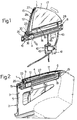
- Figure 1 is a perspective view of a window-operating device for a convertible motor vehicle, produced according to the present invention and disposed in a first operative position;
- Figure 2 is a perspective view of the device of Figure 1 mounted in a related side of the motor vehicle and located in a second operative position;
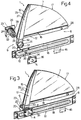
- Figure 3 is a perspective view on an enlarged scale of the device of Figure 1, with parts removed for clarity; and
- Figure 4 is an exploded perspective view of the device of Figure 3.
-
- With reference to the accompanying drawings, the reference numeral 1 generally indicates a window-operating device for a fixed or movable portion of a side 2 (Figure 2) of a convertible motor vehicle (not shown), in the example, for a door of the motor vehicle itself.
- The
side 2 comprises a box-like body 3 constituted by anouter body element 4 and an inner covering panel 5, and defines a space 6 for accommodating arelated window 7 moved by the device 1. - According to the present invention, the device 1 essentially comprises a
support frame 8 carrying thewindow 7 and attached, in use, to thebody 3 of theside 2, and a male andfemale screw assembly 9 interposed between thewindow 7 and theframe 8, which enables thewindow 7 to move, in use, between a lowered, or open, position (Figure 2) in which it is completely housed in the space 6 in thebody 3, and a raised, or closed, position (Figures 1, 3 and 4) in which thewindow 7 projects upwards from thebody 3 itself; in particular, theassembly 9 enables thewindow 7 to turn, in use, about an axis A transverse to thebody element 4 and the panel 5 of theside 2, between the lowered and raised positions, and causes thewindow 7 to translate along the axis A itself during this turning movement. - The
frame 8 includes anattachment assembly 10 firmly fixed to thebody 3 of theside 2 at anupper opening 11 in thebody 3 itself, and asupport element 12 fixed peripherally to thewindow 7 and movably attached to theattachment assembly 10 by male andfemale screw assembly 9. - The
window 7 is substantially triangular in shape and is laterally delimited by twoedges curved edge 17 which connects the respective free ends of theedges window 7 is in the raised position, theedge 15 extends vertically out of thebody 3 and theedge 16 extends horizontally along theopening 11 while, when thewindow 7 is in the lowered position, theedge 15 extends horizontally along theopening 11 and theedge 16 extends vertically within the space 6 within thebody 3 itself. - The
attachment assembly 10 includes a substantially flat,elongate plate 18 fixed byscrews 19 at its end to an upper portion of the panel 5 of thebody 3 in correspondence with theopening 11 and which extends, in use, at right angles to the axis A. - The
plate 18 has an integralflat element 20 which projects at right angles from an end portion and extends, in use, towards thebody element 4 of thebody 3; theattachment assembly 10 further includes an L-shape bracket 23 with a firstflat portion 24 at right angles to theplate 18 and releasably attached to theelement 20 by means of associatedscrews 25, and a secondflat portion 26 facing theplate 18 and disposed, in use, against an inner face of thebody element 4. - The
support element 12 is substantially L-shape and includes first andsecond arms respective edges window 7. In particular, thearm 28 projects from thearm 27 and subdivides thearm 27 itself into amain portion 29 firmly attached to theedge 15 of thewindow 7, and anend portion 30 terminating in an internally threaded cylindrical tubular element which is, in use, coaxial with the axis A and defines anut 31 of thescrew assembly 9. - The
assembly 9 further includes ascrew 32 with an axis A supported firmly between theplate 18 and theportion 26 of therod 27 which coaxially engages thenut 31. - According to an important characteristic of the device 1, when the
window 7 is in the lowered position, thearm 27 of thesupport element 12 is disposed horizontally within theopening 11 so that, together with associated seals (not shown) of thewindow 7, it closes theopening 11 itself and, therefore, the space 6 in thebody 3. - With particular reference to Figure 4, the
screw 32 projects fully from theportion 26 of therod 23, and has an axialblind hole 33 engaged, in use, by acentring pin 34 located so that it passes through ahole 35 in theplate 18 and projects completely from aplate 36 fixed by screws to a face of theplate 18 facing the interior of the motor vehicle. - Finally, the
nut 31 andscrew 32 haverespective threads window 7 turns from the raised position to the lowered position, it translates along the axis A towards the interior of the motor vehicle. - With reference to Figure 1, the device 1 finally includes an electric drive unit 40 (known and therefore not described in detail) co-operating with the
assembly 9 in order to move thewindow 7 between the lowered and raised positions. - The
drive unit 40 is of the kind having a movable cable and essentially includes asupport body 41, anelectric motor 42 carried by thebody 41 and anoutput cable 43 axially moved by theelectric motor 42 and attached to a free end portion of thearm 28. - Preferably, the
body 41 is fixed to arod 46 projecting from theplate 18 in such a way that thedrive unit 40, theframe 8, thewindow 7 and the male andfemale screw assembly 9 together define a unit which can be pre-assembled and mounted in thebody 3 of theside 2. - From an examination of the characteristics of the device 1 formed according to the present invention, the advantages conferred thereby are clear.
- In particular, the male and
female screw assembly 9 enables theassociated window 7 to turn about the axis A from the raised position to the lowered position and vice versa, with a contemporaneous translation of thewindow 7 itself along the axis A towards the interior of the motor vehicle and vice versa. Therefore, by virtue of this movement, the curved profile of thewindow 7 does not interfere with the structure or shape of the internal shell of the motor vehicle, which cannot have specific curvature; this means that it is possible, without a related increase in costs, to utilise a large variety of windows having a curvilinear shape, and, in particular, cylindrical windows. This system of movement also enables the transverse sizes of the related motor vehicles provided with windows having particularly accentuated arcuate profiles to be limited. - In addition, the combined turning and translation movement caused by the
screw assembly 9 facilitates the movement of the window between the lowered and raised positions, in that any sliding between thewindow 7 itself and the associated seals on theside 2 is reduced to a minimum. - Preferably, the
frame 8, thewindow 7, thescrew assembly 9 and thedrive unit 40 define an assembly that can be pre-assembled, enabling operations for mounting the device 1 on theside 2 to be significantly simpler than those for mounting conventional window-operating devices. - Finally, according to a secondary characteristic of the present invention, the
arm 27 of thesupport element 12 is shaped so that, together with the seals for thewindow 7, the space 6 in the side is closed when thewindow 7 itself is in the lowered position. - Finally, it is clear that modifications and variations can be introduced to the device 1 which do not depart from the ambit of protection of the present invention.
- In particular, the
support body 41 of thedrive unit 40 could be fixed directly to the box-like body 3 of theside 2. - In addition, the
electric drive unit 40 could be replaced by a manual drive unit comprising a control handle on the panel 5 of theside 2, and a transmission unit for the motor interposed between the handle itself and thearm 28 of thesupport element 12.
Claims (8)
- A window-operating device (1) for a side (2) of a motor vehicle, in particular for a side of a convertible motor vehicle, the said side (2) including at least one box-like body (3) defining a space (6) for accommodating an associated window (7), the said device (1) being characterised in that it includes support means (8) attached to the said box-like body (3) of the said side (2), means (9) for the attachment of the said window (7) for turning movement with the said support means (8) to enable the window (7) to turn, in use, about an axis (A) transverse to the said side (2) between a lowered position in which the said window (7) is located completely within the said space (6) in the said box-like body (3), and a raised position in which the said window (7) projects upwards from the said box-like body (3), and transmission means (37, 38) for causing the translation of the said window (7) along the said axis (A) during the turning of the window (7) between the said lowered and raised positions.
- A device according to Claim 1, characterised in that it includes drive means (40) co-operating with the attachment means (31, 32) and the said transmission means (37, 38) in order to move the said window (7) between the said raised and lowered positions, and in that the said support means (8), the said window (7), the said attachment means (9), the said transmission means (37, 38) and the said drive means (40) define a unit which can be pre-assembled and mounted on the said side (2).
- A device according to Claim 1 or 2, characterised in that the said support means (8) include fixing means (10) attached firmly to the said box-like body (3), and in that the said attachment means and the said transmission means include a male and female screw assembly (9) interposed between the said fixing means (10) and the said window (7).
- A device according to Claim 3, characterised in that the said male and female screw assembly (9) includes a screw (32) coaxial to the said axis (A), in use, and attached to one of the said window (7) and the said fixing means (10), and a nut (31) engaged by the said screw (32) and carried by the other of the said window (7) and said fixing means (10).
- A device according to Claim 4, characterised in that the said screw (32) and the said nut (31) have associated threads (38, 37) inclined with respect to the said axis (A) in such a way as to cause the window, during its turning movement from the said raised position to the said lowered position, to move along the said axis (A) towards the interior of the said motor vehicle.
- A device according to Claim 4 or Claim 5, characterised in that the said support means (8) include a support element (12) fixed peripherally to the said window (7) and movably attached to the said fixing means (10) by means of the said male and female screw assembly (9), the said screw (32) being fixed to the said fixing means (10) and the said nut (31) being fixed to the said support element (12).
- A device according to Claim 6, characterised in that the said fixing means (10) include an elongate plate (18) fixed to the said box-like body (3) in correspondence with an upper opening (11) therein, and in a direction transverse to the said axis (A), the said screw (32) being carried on the said plate (18) and projecting from the plate (18) itself, the said support element (12) including at least one elongate arm (27) fixed to a side edge (15) of the said window (7), provided at one of its ends with the said nut (31) and which closes the said upper opening (11) in the said box-like body (3) when the said window (7) is in the said lowered position.
- A device according to Claim 7, characterised in that the said drive means include an electric drive unit (40), and in that the said plate (18) has a bracket (46) for fixing the said electric drive unit (40).
Applications Claiming Priority (2)
| Application Number | Priority Date | Filing Date | Title |
|---|---|---|---|
| IT97TO000863A IT1295452B1 (en) | 1997-09-30 | 1997-09-30 | WINDOW LIFTER DEVICE FOR A MOTOR VEHICLE, IN PARTICULAR FOR A DECAPPABLE CAR. |
| ITTO970863 | 1997-09-30 |
Publications (3)
| Publication Number | Publication Date |
|---|---|
| EP0904966A2 true EP0904966A2 (en) | 1999-03-31 |
| EP0904966A3 EP0904966A3 (en) | 1999-06-23 |
| EP0904966B1 EP0904966B1 (en) | 2004-03-10 |
Family
ID=11416033
Family Applications (1)
| Application Number | Title | Priority Date | Filing Date |
|---|---|---|---|
| EP98118149A Expired - Lifetime EP0904966B1 (en) | 1997-09-30 | 1998-09-24 | A window-operating device for a motor vehicle, in particular for a convertible motor vehicle |
Country Status (4)
| Country | Link |
|---|---|
| EP (1) | EP0904966B1 (en) |
| DE (1) | DE69822259T2 (en) |
| ES (1) | ES2216224T3 (en) |
| IT (1) | IT1295452B1 (en) |
Cited By (6)
| Publication number | Priority date | Publication date | Assignee | Title |
|---|---|---|---|---|
| WO2001053124A1 (en) * | 2000-01-21 | 2001-07-26 | Brose Fahrzeugteile Gmbh & Co. Kg, Coburg | Method and device for adjusting a window glass, in particular on a cabriolet, with anti-trap protection |
| DE10140231A1 (en) * | 2001-08-22 | 2003-04-10 | Karmann Gmbh W | Motor vehicle has esp. rear side windows which can be lowered even when neighboring body sections are at an acute angle to windows |
| FR2830508A1 (en) * | 2001-10-10 | 2003-04-11 | Meritor Light Vehicle Sys Ltd | Assembly method for window drive of motor vehicle involves placing drive into seating and covering gap with mask plate |
| WO2006000596A1 (en) * | 2004-06-23 | 2006-01-05 | Melchor Daumal Castellon | Device for actuating the rear side windows of a convertible vehicle |
| FR2885937A1 (en) * | 2005-05-17 | 2006-11-24 | Arvinmeritor Light Vehicle Sys | DEVICE FOR OPERATING AN OPENING AND OPENING GLASS OF A VEHICLE |
| DE102014113061A1 (en) * | 2014-09-10 | 2016-03-10 | Dr. Ing. H.C. F. Porsche Aktiengesellschaft | Vehicle body and manufacturing method for such |
Family Cites Families (4)
| Publication number | Priority date | Publication date | Assignee | Title |
|---|---|---|---|---|
| FR1382296A (en) * | 1963-11-07 | 1964-12-18 | Applic Ind Soc Et | Convertible vehicle |
| US3273285A (en) * | 1964-01-31 | 1966-09-20 | Gen Motors Corp | Window regulator mechanism |
| DE3907175C1 (en) * | 1989-03-03 | 1990-08-23 | Audi Ag, 8070 Ingolstadt, De | |
| US5685596A (en) * | 1995-01-31 | 1997-11-11 | Asc Incorporated | Window lift mechanism for an automotive vehicle |
-
1997
- 1997-09-30 IT IT97TO000863A patent/IT1295452B1/en active IP Right Grant
-
1998
- 1998-09-24 ES ES98118149T patent/ES2216224T3/en not_active Expired - Lifetime
- 1998-09-24 EP EP98118149A patent/EP0904966B1/en not_active Expired - Lifetime
- 1998-09-24 DE DE69822259T patent/DE69822259T2/en not_active Expired - Fee Related
Non-Patent Citations (1)
| Title |
|---|
| None |
Cited By (12)
| Publication number | Priority date | Publication date | Assignee | Title |
|---|---|---|---|---|
| WO2001053124A1 (en) * | 2000-01-21 | 2001-07-26 | Brose Fahrzeugteile Gmbh & Co. Kg, Coburg | Method and device for adjusting a window glass, in particular on a cabriolet, with anti-trap protection |
| US6773053B2 (en) | 2000-01-21 | 2004-08-10 | Brose Fahrzeugtelle Gmbh & Co. Kg, Coburg | Method and device for adjusting a window glass, in particular on a cabriolet, with anti-trap protection |
| DE10140231A1 (en) * | 2001-08-22 | 2003-04-10 | Karmann Gmbh W | Motor vehicle has esp. rear side windows which can be lowered even when neighboring body sections are at an acute angle to windows |
| DE10140231B4 (en) * | 2001-08-22 | 2005-01-20 | Wilhelm Karmann Gmbh | Motor vehicle with side windows |
| FR2830508A1 (en) * | 2001-10-10 | 2003-04-11 | Meritor Light Vehicle Sys Ltd | Assembly method for window drive of motor vehicle involves placing drive into seating and covering gap with mask plate |
| EP1302346A1 (en) * | 2001-10-10 | 2003-04-16 | Arvinmeritor Light Vehicle Systems-France | Window opener for convertible rear window and its mounting procedure |
| WO2006000596A1 (en) * | 2004-06-23 | 2006-01-05 | Melchor Daumal Castellon | Device for actuating the rear side windows of a convertible vehicle |
| ES2255393A1 (en) * | 2004-06-23 | 2006-06-16 | Melchor Daumal Castellon | Device for actuating the rear side windows of a convertible vehicle |
| US8225551B2 (en) | 2004-06-23 | 2012-07-24 | Melchor Daumal Castellon | Device for operating rear side windows of convertible vehicles |
| FR2885937A1 (en) * | 2005-05-17 | 2006-11-24 | Arvinmeritor Light Vehicle Sys | DEVICE FOR OPERATING AN OPENING AND OPENING GLASS OF A VEHICLE |
| DE102014113061A1 (en) * | 2014-09-10 | 2016-03-10 | Dr. Ing. H.C. F. Porsche Aktiengesellschaft | Vehicle body and manufacturing method for such |
| DE102014113061B4 (en) | 2014-09-10 | 2023-01-12 | Dr. Ing. H.C. F. Porsche Aktiengesellschaft | vehicle body |
Also Published As
| Publication number | Publication date |
|---|---|
| EP0904966A3 (en) | 1999-06-23 |
| DE69822259T2 (en) | 2005-03-03 |
| IT1295452B1 (en) | 1999-05-12 |
| ITTO970863A1 (en) | 1999-03-30 |
| ES2216224T3 (en) | 2004-10-16 |
| DE69822259D1 (en) | 2004-04-15 |
| EP0904966B1 (en) | 2004-03-10 |
Similar Documents
| Publication | Publication Date | Title |
|---|---|---|
| US5836110A (en) | Remote manual anti-backdrive system for modular rear-mounted window assembly | |
| US4811985A (en) | Automobile roof having a lid associated with a roof opening | |
| US5613323A (en) | Cable drive assembly for a window | |
| US5724769A (en) | Motor vehicle window construction with pull-pull cable system | |
| AU3015697A (en) | Swivel-sliding door system for a vehicle | |
| US4531777A (en) | Motor vehicle roof arrangement of the type interchangeably driveable by both motor and crank drives | |
| GB2169652A (en) | An extending device for window panes, lifting roofs or the like openable structures | |
| EP0134042A2 (en) | Sliding and venting sunroof | |
| AU2006801A (en) | Actuator for gates, doors and the like | |
| US5456516A (en) | Automotive vehicle side window system | |
| EP0904966A2 (en) | A window-opperating device for a motor vehicle, in particular for a convertible motor vehicle | |
| US10618386B2 (en) | Electric sunshade and sunroof structure | |
| US3605338A (en) | Sliding door,particularly for motor vehicles | |
| CA2536753A1 (en) | Vehicle sunroof assembly | |
| US4971387A (en) | Air guide device for an automobile roof | |
| CA2465821C (en) | A sunroof with lead screw drive element | |
| US4589227A (en) | Side window glass regulator for quarter windows on convertibles | |
| EP1943405B1 (en) | Door system and vehicle provided with such a door system | |
| US5720508A (en) | Powered glare screen device | |
| US4168594A (en) | Remote controller for hinged window | |
| US5195211A (en) | Guide channel pivot for window regulator | |
| CN100396876C (en) | Handle, in particular for motor car doors | |
| WO1982003105A1 (en) | Automobile window structure | |
| US6810625B2 (en) | Vehicle door auxiliary window assembly | |
| GB2298445A (en) | Sliding window or door |
Legal Events
| Date | Code | Title | Description |
|---|---|---|---|
| PUAI | Public reference made under article 153(3) epc to a published international application that has entered the european phase |
Free format text: ORIGINAL CODE: 0009012 |
|
| AK | Designated contracting states |
Kind code of ref document: A2 Designated state(s): DE ES FR GB SE |
|
| AX | Request for extension of the european patent |
Free format text: AL;LT;LV;MK;RO;SI |
|
| PUAL | Search report despatched |
Free format text: ORIGINAL CODE: 0009013 |
|
| AK | Designated contracting states |
Kind code of ref document: A3 Designated state(s): AT BE CH CY DE DK ES FI FR GB GR IE IT LI LU MC NL PT SE |
|
| AX | Request for extension of the european patent |
Free format text: AL;LT;LV;MK;RO;SI |
|
| RIC1 | Information provided on ipc code assigned before grant |
Free format text: 6B 60J 7/12 A, 6B 60J 1/14 B, 6E 05F 11/52 B |
|
| RTI1 | Title (correction) |
Free format text: A WINDOW-OPERATING DEVICE FOR A MOTOR VEHICLE, IN PARTICULAR FOR A CONVERTIBLE MOTOR VEHICLE |
|
| 17P | Request for examination filed |
Effective date: 19991221 |
|
| AKX | Designation fees paid |
Free format text: DE ES FR GB SE |
|
| 17Q | First examination report despatched |
Effective date: 20011203 |
|
| REG | Reference to a national code |
Ref country code: GB Ref legal event code: FG4D |
|
| GRAP | Despatch of communication of intention to grant a patent |
Free format text: ORIGINAL CODE: EPIDOSNIGR1 |
|
| GRAS | Grant fee paid |
Free format text: ORIGINAL CODE: EPIDOSNIGR3 |
|
| GRAA | (expected) grant |
Free format text: ORIGINAL CODE: 0009210 |
|
| AK | Designated contracting states |
Kind code of ref document: B1 Designated state(s): DE ES FR GB SE |
|
| REF | Corresponds to: |
Ref document number: 69822259 Country of ref document: DE Date of ref document: 20040415 Kind code of ref document: P |
|
| PGFP | Annual fee paid to national office [announced via postgrant information from national office to epo] |
Ref country code: ES Payment date: 20040903 Year of fee payment: 7 |
|
| PGFP | Annual fee paid to national office [announced via postgrant information from national office to epo] |
Ref country code: GB Payment date: 20040917 Year of fee payment: 7 |
|
| REG | Reference to a national code |
Ref country code: ES Ref legal event code: FG2A Ref document number: 2216224 Country of ref document: ES Kind code of ref document: T3 |
|
| ET | Fr: translation filed | ||
| PLBE | No opposition filed within time limit |
Free format text: ORIGINAL CODE: 0009261 |
|
| STAA | Information on the status of an ep patent application or granted ep patent |
Free format text: STATUS: NO OPPOSITION FILED WITHIN TIME LIMIT |
|
| 26N | No opposition filed |
Effective date: 20041213 |
|
| PGFP | Annual fee paid to national office [announced via postgrant information from national office to epo] |
Ref country code: SE Payment date: 20050809 Year of fee payment: 8 |
|
| PG25 | Lapsed in a contracting state [announced via postgrant information from national office to epo] |
Ref country code: GB Free format text: LAPSE BECAUSE OF NON-PAYMENT OF DUE FEES Effective date: 20050924 |
|
| PG25 | Lapsed in a contracting state [announced via postgrant information from national office to epo] |
Ref country code: SE Free format text: LAPSE BECAUSE OF NON-PAYMENT OF DUE FEES Effective date: 20050925 |
|
| PG25 | Lapsed in a contracting state [announced via postgrant information from national office to epo] |
Ref country code: ES Free format text: LAPSE BECAUSE OF NON-PAYMENT OF DUE FEES Effective date: 20050926 |
|
| EUG | Se: european patent has lapsed | ||
| GBPC | Gb: european patent ceased through non-payment of renewal fee |
Effective date: 20050924 |
|
| PGFP | Annual fee paid to national office [announced via postgrant information from national office to epo] |
Ref country code: FR Payment date: 20060825 Year of fee payment: 9 |
|
| PGFP | Annual fee paid to national office [announced via postgrant information from national office to epo] |
Ref country code: DE Payment date: 20061027 Year of fee payment: 9 |
|
| REG | Reference to a national code |
Ref country code: ES Ref legal event code: FD2A Effective date: 20050926 |
|
| PG25 | Lapsed in a contracting state [announced via postgrant information from national office to epo] |
Ref country code: DE Free format text: LAPSE BECAUSE OF NON-PAYMENT OF DUE FEES Effective date: 20080401 |
|
| REG | Reference to a national code |
Ref country code: FR Ref legal event code: ST Effective date: 20080531 |
|
| PG25 | Lapsed in a contracting state [announced via postgrant information from national office to epo] |
Ref country code: FR Free format text: LAPSE BECAUSE OF NON-PAYMENT OF DUE FEES Effective date: 20071001 |