EP0903927B1 - MOS transistors circuit having a transformer/data interface function - Google Patents
MOS transistors circuit having a transformer/data interface function Download PDFInfo
- Publication number
- EP0903927B1 EP0903927B1 EP97830462A EP97830462A EP0903927B1 EP 0903927 B1 EP0903927 B1 EP 0903927B1 EP 97830462 A EP97830462 A EP 97830462A EP 97830462 A EP97830462 A EP 97830462A EP 0903927 B1 EP0903927 B1 EP 0903927B1
- Authority
- EP
- European Patent Office
- Prior art keywords
- substitutive
- voltage
- mos transistors
- transistors
- supply
- Prior art date
- Legal status (The legal status is an assumption and is not a legal conclusion. Google has not performed a legal analysis and makes no representation as to the accuracy of the status listed.)
- Expired - Lifetime
Links
Images


Classifications
-
- H—ELECTRICITY
- H04—ELECTRIC COMMUNICATION TECHNIQUE
- H04Q—SELECTING
- H04Q11/00—Selecting arrangements for multiplex systems
- H04Q11/04—Selecting arrangements for multiplex systems for time-division multiplexing
- H04Q11/0428—Integrated services digital network, i.e. systems for transmission of different types of digitised signals, e.g. speech, data, telecentral, television signals
- H04Q11/0435—Details
-
- H—ELECTRICITY
- H04—ELECTRIC COMMUNICATION TECHNIQUE
- H04L—TRANSMISSION OF DIGITAL INFORMATION, e.g. TELEGRAPHIC COMMUNICATION
- H04L12/00—Data switching networks
-
- H—ELECTRICITY
- H04—ELECTRIC COMMUNICATION TECHNIQUE
- H04M—TELEPHONIC COMMUNICATION
- H04M19/00—Current supply arrangements for telephone systems
- H04M19/08—Current supply arrangements for telephone systems with current supply sources at the substations
-
- H—ELECTRICITY
- H04—ELECTRIC COMMUNICATION TECHNIQUE
- H04Q—SELECTING
- H04Q2213/00—Indexing scheme relating to selecting arrangements in general and for multiplex systems
- H04Q2213/13003—Constructional details of switching devices
-
- H—ELECTRICITY
- H04—ELECTRIC COMMUNICATION TECHNIQUE
- H04Q—SELECTING
- H04Q2213/00—Indexing scheme relating to selecting arrangements in general and for multiplex systems
- H04Q2213/1308—Power supply
-
- H—ELECTRICITY
- H04—ELECTRIC COMMUNICATION TECHNIQUE
- H04Q—SELECTING
- H04Q2213/00—Indexing scheme relating to selecting arrangements in general and for multiplex systems
- H04Q2213/13082—Power supply via phantom line
-
- H—ELECTRICITY
- H04—ELECTRIC COMMUNICATION TECHNIQUE
- H04Q—SELECTING
- H04Q2213/00—Indexing scheme relating to selecting arrangements in general and for multiplex systems
- H04Q2213/1309—Apparatus individually associated with a subscriber line, line circuits
-
- H—ELECTRICITY
- H04—ELECTRIC COMMUNICATION TECHNIQUE
- H04Q—SELECTING
- H04Q2213/00—Indexing scheme relating to selecting arrangements in general and for multiplex systems
- H04Q2213/13166—Fault prevention
-
- H—ELECTRICITY
- H04—ELECTRIC COMMUNICATION TECHNIQUE
- H04Q—SELECTING
- H04Q2213/00—Indexing scheme relating to selecting arrangements in general and for multiplex systems
- H04Q2213/13202—Network termination [NT]
-
- H—ELECTRICITY
- H04—ELECTRIC COMMUNICATION TECHNIQUE
- H04Q—SELECTING
- H04Q2213/00—Indexing scheme relating to selecting arrangements in general and for multiplex systems
- H04Q2213/13209—ISDN
-
- H—ELECTRICITY
- H04—ELECTRIC COMMUNICATION TECHNIQUE
- H04Q—SELECTING
- H04Q2213/00—Indexing scheme relating to selecting arrangements in general and for multiplex systems
- H04Q2213/13305—Transistors, semiconductors in general
-
- H—ELECTRICITY
- H04—ELECTRIC COMMUNICATION TECHNIQUE
- H04Q—SELECTING
- H04Q2213/00—Indexing scheme relating to selecting arrangements in general and for multiplex systems
- H04Q2213/1332—Logic circuits
-
- H—ELECTRICITY
- H04—ELECTRIC COMMUNICATION TECHNIQUE
- H04Q—SELECTING
- H04Q2213/00—Indexing scheme relating to selecting arrangements in general and for multiplex systems
- H04Q2213/13322—Integrated circuits
-
- Y—GENERAL TAGGING OF NEW TECHNOLOGICAL DEVELOPMENTS; GENERAL TAGGING OF CROSS-SECTIONAL TECHNOLOGIES SPANNING OVER SEVERAL SECTIONS OF THE IPC; TECHNICAL SUBJECTS COVERED BY FORMER USPC CROSS-REFERENCE ART COLLECTIONS [XRACs] AND DIGESTS
- Y02—TECHNOLOGIES OR APPLICATIONS FOR MITIGATION OR ADAPTATION AGAINST CLIMATE CHANGE
- Y02D—CLIMATE CHANGE MITIGATION TECHNOLOGIES IN INFORMATION AND COMMUNICATION TECHNOLOGIES [ICT], I.E. INFORMATION AND COMMUNICATION TECHNOLOGIES AIMING AT THE REDUCTION OF THEIR OWN ENERGY USE
- Y02D30/00—Reducing energy consumption in communication networks
- Y02D30/70—Reducing energy consumption in communication networks in wireless communication networks
Description
- reduced manufacturing costs, in view also of a homogeneous assembly with all the other dedicated circuits;
- ready elimination of any electromechanical relays for polarity reversal, and replacement thereof with active components, specifically MOS transistors;
- possible introduction of additional functions, such as matching the gains of the first RX and second TX data interfaces.
Claims (28)
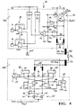
- A MOS transistors substitutive circuit having a transformer/data interface function, in particular for ISDN networks, comprising first (11a) and second (11b) power supply/transmitter blocks, said first power supply/transmitter block (11a) being connected between a voltage reference (V) and a first data interface (RX), and said second power supply/transmitter block (11b) being connected between a ground potential reference (GND) and a second data interface (TX), said first and second power supply/transmitter blocks (11a,11b) being further connected to a supply voltage reference (VDD), characterized in that the MOS transistors substitutive circuit comprises first (12) and second (12') MOS transistor pairs respectively connected to said voltage reference (V) and said ground potential reference (GND), said MOS transistors being diode configured and held in their saturation range, so as to have a high A.C. impedance and virtually zero D.C. impedance, thereby minimizing power dissipation through said substitutive circuit.
- A MOS transistors substitutive circuit according to Claim 1, characterized in that said voltage reference (V) corresponds either to a remote supply voltage (VR) or to an emergency voltage (Vem), respectively in a first condition of operation ("normal condition") characterized by the presence of a polarity reverse control signal (Scrp), and in a second condition ("RM emergency condition") characterized by the absence of the polarity reverse control signal (Scrp).
- A MOS transistors substitutive circuit according to Claim 2, characterized in that the transistors (M1,M2 - M1',M2') in said first and second pairs (12,12') are diode connected through respective connection resistors (R1,R2 - R1',R2') and are adapted to cross the same D.C. current which is flowing through the connection leads to the first and second data interfaces (RX,TX).
- A MOS transistors substitutive circuit according to Claim 3, characterized in that said second power supply/transmitter block (11b) comprises the first (M1') and the second transistor (M2') of the second pair (12'), said transistors having their gate terminals connected in common and to the respective drain terminals through the first (R1') and second connection resistors (R2') of the second pair (12'), their source terminals connected to a ground potential reference (GND), and their drain terminals connected to the second data interface (TX).
- A MOS transistors substitutive circuit according to Claim 4, characterized in that said second power supply/transmitter block (11b) further comprises first (16'), second (17'), third (20) and fourth (21) current mirrors forming a bridge connection between the supply voltage reference (VDD) and the ground potential reference (GND); in particular, said first and second current mirrors (16',17') being connected to the supply voltage reference (VDD) and to the third and fourth current mirrors (20,21), themselves connected to the ground potential reference (GND).
- A MOS transistors substitutive circuit according to Claim 5, characterized in that the first and fourth current mirrors (16',21) are connected to the first transistor of the second pair (M1') through a first decoupling element (D1) and decoupled from the second data interface (TX) by a first decoupling capacitor (C1'), while the second and third current mirrors (17',20) are connected to the second transistor of the second pair (M2') through a second decoupling element (D2) and decoupled from the second data interface (TX) by a second decoupling capacitor (C2'), said decoupling elements (D1,D2) being utilized under particular conditions of power supply to the MOS transistors substitutive circuit.
- A MOS transistors substitutive circuit according to Claim 5, characterized in that said second power supply/transmitter block (11b) further comprises a buffer (22) connected to the first and third current mirrors (16',20) through a first decoupling resistor (R5), and to the second and fourth current mirrors (17',21) through a second decoupling resistor (R6).
- A MOS transistors substitutive circuit according to Claim 7, characterized in that said buffer (22) is connected between the supply voltage reference (VDD) and the ground potential reference (GND), and connected to a reference voltage reference (VREF), thereby being adapted to set an output reference voltage (VREF) for the current mirrors (16',17',20,21), while the decoupling resistors (R5,R6) are adapted to set a suitable impedance for an A.C. signal presented to the second data interface (TX).
- A MOS transistors substitutive circuit according to Claim 5, characterized in that said second power supply/transmitter block (11b) further comprises a voltage/current converter (15') having first and second input terminals (C,D) and being connected to said first and second current mirrors (16',17').
- A MOS transistors substitutive circuit according to Claim 3, characterized in that said first power supply/transmitter block (11a) comprises the first (M1) and the second transistor (M2) of the first pair (12), said transistors having their gate terminals connected in common and to the respective drain terminals through the first (R1) and the second connection resistor (R2) of the first pair (12), their source terminals connected to the voltage reference (V) and their drain terminals connected to the first data interface (RX).
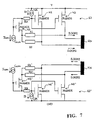
- A MOS transistors substitutive circuit according to Claim 10, characterized in that said first power supply/transmitter block (11a) further comprises a voltage/current converter (15) connected between the supply voltage reference (VDD) and the ground potential reference (GND), and connected to the drain terminals of the transistors (M1,M2) through first (C1) and second (C2) decoupling capacitors, respectively, which are themselves connected to a reference voltage reference (VREF) through first (R3) and second (R4) bias resistors.
- A MOS transistors substitutive circuit according to Claim 11, characterized in that said voltage/current converter (15) is further connected to the supply voltage reference (VDD) through first (16) and second (17) current mirrors of the first power supply/transmitter block (11a).
- A MOS transistors substitutive circuit according to Claim 12, characterized in that said first and second current mirrors (16,17) of the first power supply/transmitter block (11a) are connected to first (18) and second (19) amplifier circuits, themselves connected between the supply voltage reference (VDD) and the ground potential reference (GND) and connected, in cascade with each other, to a control terminal (OUT) of said first power supply/transmitter block (11a).
- A MOS transistors substitutive circuit according to Claim 13, characterized in that said first and second amplifier circuits (18,19) have respective output terminals (A,B); on said terminals there being present an A.C. signal output voltage which is proportional to the line voltage at the first data interface (RX) and suitably modulable by means of said first and second current mirrors (16,17) and of resistors included in the amplifier circuits (18,19).
- A MOS transistors substitutive circuit according to Claim 3, characterized in that the values of the first (R1,R1') and second (R2,R2') connection resistors are the same for the first and second transistor pairs (M1,M2 and M1',M2'), respectively, thereby being adapted to cancel, at the common gate terminal of the respective transistor pairs (12,12'), any differential signal at the first and second data interfaces (RX,TX), said transistor pairs (12,12') being adapted to offer, therefore, a high impedance to differential signals.
- A MOS transistors substitutive circuit according to Claim 3, characterized in that it further comprises a compensation current generator (Gcom) connected across the connection resistors (R1,R2-R1',R2') for extracting and injecting, respectively, a compensation current (Icom) homogeneous with the variation of said connection resistors (R1,R2-R1',R2') and, accordingly, for obtaining a constant voltage drop across said connection resistors (R1,R2-R1'-R2') effective to further reduce the power dissipated through said substitutive circuit.
- A MOS transistors substitutive circuit according to Claim 16, characterized in that it comprises a first compensation transistor (M3) connected in series with the connection resistors (R1,R2) connected to the transistors in the first pair (M1,M2) and to the voltage reference (V), and having its gate terminal connected to its drain terminal and to the compensation current generator (Gcom), its drain terminal further connected to the common gate terminal of the transistors (M1,M2) in the first pair (12) through a first match resistor (RA), and its source terminal connected to said connection resistors (R1,R2), and a second compensation transistor (M3') connected in series with the connection resistors (R1',R2') connected to the transistors in second pair (M1', M2') and to the ground potential reference (GND), and having its gate terminal connected to its drain terminal and to the compensation current generator (Gcom), its drain terminal further connected to the common gate terminal of the transistors (M1',M2') in the second pair (12') through a second match resistor (RB), and its source terminal connected to said connection resistors (R1',R2') connected to the transistors in the second pair (M1', M2'), said compensation transistors (M3,M3') being thus diode configured and having a voltage drop which virtually equals a MOS transistor threshold voltage (VT), so as to compensate the threshold voltages of the transistors employed, with respect to temperature and process variations.
- A MOS transistors substitutive circuit according to, Claim 17, characterized in that the first compensation transistor (M3) has its source terminal further connected to the voltage reference (V) through a series of said first match resistor (RA) and a first match current generator (GA), and that the second compensation transistor (M3') has its source terminal further connected to the ground potential reference (GND) through a series of said second match resistor (RB) and a second match current generator (GB), said current generators (GA,GB) thus being adapted to allow the voltages across the connection resistors (R1,R2-R1',R2') of the first and second pairs (12,12') to be modulated through the respective match resistors (RA,RB) for optimum adjustment, at the manufacturing stage, of said substitutive circuit, a further reduction of the dissipated power, and inherent compensation of the effects of temperature and process variations on the threshold voltage (VT) of the transistors employed.
- A MOS transistors substitutive circuit according to Claim 1, characterized in that said first and second pairs (12,12') comprise MOS transistors of a first and a second type (PMOS,NMOS), respectively.
- A MOS transistors substitutive circuit according to Claim 19, characterized in that said first and second transistor pairs (12,12') can be constructed from basic components available from conventional mixed technologies of the BCD type.
- A MOS transistors substitutive circuit according to Claims 17 and 19, characterized in that said first and second compensation transistors (M3,M3') are respectively of the same type as the transistors (M1,M2-M1',M2') in the first and second pairs (12,12').
- A MOS transistors substitutive circuit according to Claim 4, characterized in that the source terminals of said first (M1') and second (M2') transistors in the second pair (12') are connected to the ground potential reference (GND) through a sensing resistor (Rgnd).
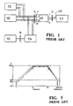
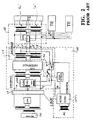
- A control and driving switch apparatus for substitutive transformer/data transmitter circuits in a network termination, in particular for an ISDN network, said network termination including first (2) and second (3) converters connected to a ground potential reference (GND), said first converter (2) adapted to deliver a supply voltage (VDD) and an emergency voltage (Vem), and said second converter (3) adapted to deliver a remote supply voltage (VR), characterized in that the control and driving switch apparatus comprises at least first (11) and second (11') MOS transistors substitutive circuits according to any of the preceding claims, which circuits respectively are adapted to operate in a first condition of operation ("normal condition") of the network termination characterized by the presence of the polarity reverse control signal (Scrp), and a second condition of operation ("RM emergency condition") of the network termination characterized by the absence of the polarity reverse control signal (Scrp).
- A control apparatus according to Claim 23, characterized in that said first and second MOS transistors substitutive circuits (11,11') are connected to a signal line (BUS1) whereon is present a polarity reverse control signal (Scrp) which is generated by the second converter (3) of the network termination, and are connected to first and second data interfaces (RX,TX).
- A control apparatus according to Claim 24, characterized in that said first MOS transistors substitutive circuit (11) comprises first and second normal supply blocks (5,7), said first normal supply block (5) being adapted to receive said remote supply voltage (VR) from the second converter (3) and being connected to the signal line (BUS1) through a first logic inverter (9) and to the first data interface (RX), and said second normal supply block (7) being connected to the signal line (BUS1) through a second logic inverter (10), and connected to the second data interface (TX).
- A control apparatus according to Claim 25, characterized in that said second MOS transistors substitutive circuit (11') comprises first and second emergency supply blocks (4,8), said first emergency supply block (4) being adapted to receive said emergency voltage (Vem) from the first converter (2) through a current limiter (6), and being connected to said second normal supply block (7) and to the second data interface (TX), and said second emergency supply block (8) being connected to said first normal supply block (5) and to the first data interface (RX).
- A control apparatus according to Claim 26, characterized by that, in the first condition ("normal condition") of operation of the network termination, the remote supply voltage (VR) is present, which voltage is crossed through the first normal supply block (5) to the first data interface (RX), and from the second data interface (TX) to ground through the second normal supply block (7).
- A control apparatus according to Claim 27, characterized by that, in the second condition ("RM emergency condition") of operation of the network termination, the emergency voltage (Vem) is present, and the polarity reverse control signal (Scrp) present on the signal line (BUS1) enables the emergency supply blocks (4,8) and disables the normal supply blocks (5,7) through said first and second inverters (9,10).
Priority Applications (3)
| Application Number | Priority Date | Filing Date | Title |
|---|---|---|---|
| DE69729447T DE69729447D1 (en) | 1997-09-23 | 1997-09-23 | MOS transistor circuit with transformer / data interface function |
| EP97830462A EP0903927B1 (en) | 1997-09-23 | 1997-09-23 | MOS transistors circuit having a transformer/data interface function |
| US09/159,526 US6560333B1 (en) | 1997-09-23 | 1998-09-23 | MOS transistors substitute circuit having a transformer/data interface function, particularly for ISDN networks and corresponding control and driving switch configuration |
Applications Claiming Priority (1)
| Application Number | Priority Date | Filing Date | Title |
|---|---|---|---|
| EP97830462A EP0903927B1 (en) | 1997-09-23 | 1997-09-23 | MOS transistors circuit having a transformer/data interface function |
Publications (2)
| Publication Number | Publication Date |
|---|---|
| EP0903927A1 EP0903927A1 (en) | 1999-03-24 |
| EP0903927B1 true EP0903927B1 (en) | 2004-06-09 |
Family
ID=8230777
Family Applications (1)
| Application Number | Title | Priority Date | Filing Date |
|---|---|---|---|
| EP97830462A Expired - Lifetime EP0903927B1 (en) | 1997-09-23 | 1997-09-23 | MOS transistors circuit having a transformer/data interface function |
Country Status (3)
| Country | Link |
|---|---|
| US (1) | US6560333B1 (en) |
| EP (1) | EP0903927B1 (en) |
| DE (1) | DE69729447D1 (en) |
Families Citing this family (7)
| Publication number | Priority date | Publication date | Assignee | Title |
|---|---|---|---|---|
| US6480510B1 (en) | 1998-07-28 | 2002-11-12 | Serconet Ltd. | Local area network of serial intelligent cells |
| US6956826B1 (en) | 1999-07-07 | 2005-10-18 | Serconet Ltd. | Local area network for distributing data communication, sensing and control signals |
| US6690677B1 (en) | 1999-07-20 | 2004-02-10 | Serconet Ltd. | Network for telephony and data communication |
| US6549616B1 (en) | 2000-03-20 | 2003-04-15 | Serconet Ltd. | Telephone outlet for implementing a local area network over telephone lines and a local area network using such outlets |
| AT409206B (en) * | 2000-03-22 | 2002-06-25 | Ericsson Ahead Comm Systems Gm | CIRCUIT FOR THE POWER SUPPLY OF A MAINS TERMINAL UNIT |
| IL154234A (en) | 2003-01-30 | 2010-12-30 | Mosaid Technologies Inc | Method and system for providing dc power on local telephone lines |
| IL159838A0 (en) | 2004-01-13 | 2004-06-20 | Yehuda Binder | Information device |
Family Cites Families (8)
| Publication number | Priority date | Publication date | Assignee | Title |
|---|---|---|---|---|
| US3649769A (en) * | 1970-10-28 | 1972-03-14 | Gen Electric | Circuit for supplying direct current to a telephone line |
| US4173714A (en) * | 1977-06-03 | 1979-11-06 | Tie/Communications, Inc. | Communication circuit with combined power feed and data transmission over a phantom channel |
| GB2104330A (en) * | 1981-08-19 | 1983-03-02 | Texas Instruments Ltd | Improvements in or relating to amplifiers |
| CA1211241A (en) * | 1984-04-30 | 1986-09-09 | Joseph W. Hingston | Line feed circuit for a digital signal loop |
| FR2614737B1 (en) * | 1987-04-29 | 1989-06-09 | Cit Alcatel | BACKUP CONTINUOUS ELECTRICAL POWER SUPPLY WITH EMERGENCY STATUS SIGNALING BY POLARITY REVERSE |
| IT1253679B (en) * | 1991-08-30 | 1995-08-22 | Sgs Thomson Microelectronics | RESET CIRCUIT ON SWITCHING ON OF AN INTEGRATED CIRCUIT WITH NO STATIC CONSUMPTION. |
| EP0657995B1 (en) * | 1993-12-07 | 1999-10-13 | STMicroelectronics S.r.l. | Mixed typology output stage |
| EP0821362B1 (en) * | 1996-07-24 | 2004-05-26 | STMicroelectronics S.r.l. | Output stage for a memory device and for low voltage applications |
-
1997
- 1997-09-23 DE DE69729447T patent/DE69729447D1/en not_active Expired - Lifetime
- 1997-09-23 EP EP97830462A patent/EP0903927B1/en not_active Expired - Lifetime
-
1998
- 1998-09-23 US US09/159,526 patent/US6560333B1/en not_active Expired - Lifetime
Also Published As
| Publication number | Publication date |
|---|---|
| EP0903927A1 (en) | 1999-03-24 |
| US6560333B1 (en) | 2003-05-06 |
| DE69729447D1 (en) | 2004-07-15 |
Similar Documents
| Publication | Publication Date | Title |
|---|---|---|
| US4431868A (en) | Solid state telephone line interface circuit with ringing capability | |
| US5856758A (en) | Low distortion driver employing positive feedback for reducing power loss in output impedance that effectively matches the impedance of driven line | |
| US4514595A (en) | Active impedance line feed circuit | |
| AU644162B2 (en) | Telecommunications line circuit | |
| EP0724345B1 (en) | Transmission method and transmitter with a decoupled low level and at least one coupled high level, interface circuit and system component for a telecommunication network which includes such a transmitter | |
| US4203009A (en) | Unbalanced/balanced converter circuits | |
| US4797904A (en) | Transmitter for ISDN S-bus interface circuit | |
| EP0903927B1 (en) | MOS transistors circuit having a transformer/data interface function | |
| CA1292588C (en) | Subscriber line interface circuit | |
| US4677667A (en) | Subscriber line circuit having improved AC impedance matching | |
| US5274702A (en) | Wideband telephone line interface circuit | |
| US5661794A (en) | Telephone line interface circuit with voltage control | |
| US5940498A (en) | Electronic voice circuit configuration | |
| US5343520A (en) | Impedance synthesis multile loop using filtering means | |
| GB2071461A (en) | Telephone line feed | |
| US5528688A (en) | Telephone battery feed circuit including noise reduction circuit | |
| US6873703B1 (en) | Precision, low-power current-sense transmission channel for subscriber line interface circuit, programmable with single ended impedances and capable of exhibiting a voltage sense response | |
| US4538032A (en) | Interface circuit with impedance adaptation means | |
| US4113996A (en) | Voltage controlled current sources for active hybrid circuit | |
| JPS63155931A (en) | Digital signal transmission circuit | |
| US4361732A (en) | Trunk interface circuit with current compensation | |
| JPH08307523A (en) | Subscriber line interface circuit and method generating ringsignal allowing sinchronous drive of a plurality of rings inside thereof | |
| US5789959A (en) | Circuit configuration for direct voltage and alternating voltage decoupling | |
| EP0096473B1 (en) | Active impedance line feed circuit | |
| EP0186214B1 (en) | Battery-feed circuit for exchange |
Legal Events
| Date | Code | Title | Description |
|---|---|---|---|
| PUAI | Public reference made under article 153(3) epc to a published international application that has entered the european phase |
Free format text: ORIGINAL CODE: 0009012 |
|
| AK | Designated contracting states |
Kind code of ref document: A1 Designated state(s): DE FR GB IT |
|
| AX | Request for extension of the european patent |
Free format text: AL;LT;LV;RO;SI |
|
| 17P | Request for examination filed |
Effective date: 19990622 |
|
| AKX | Designation fees paid |
Free format text: DE FR GB IT |
|
| GRAP | Despatch of communication of intention to grant a patent |
Free format text: ORIGINAL CODE: EPIDOSNIGR1 |
|
| GRAS | Grant fee paid |
Free format text: ORIGINAL CODE: EPIDOSNIGR3 |
|
| GRAA | (expected) grant |
Free format text: ORIGINAL CODE: 0009210 |
|
| AK | Designated contracting states |
Kind code of ref document: B1 Designated state(s): DE FR GB IT |
|
| REG | Reference to a national code |
Ref country code: GB Ref legal event code: FG4D |
|
| REF | Corresponds to: |
Ref document number: 69729447 Country of ref document: DE Date of ref document: 20040715 Kind code of ref document: P |
|
| PG25 | Lapsed in a contracting state [announced via postgrant information from national office to epo] |
Ref country code: DE Free format text: LAPSE BECAUSE OF FAILURE TO SUBMIT A TRANSLATION OF THE DESCRIPTION OR TO PAY THE FEE WITHIN THE PRESCRIBED TIME-LIMIT Effective date: 20040910 |
|
| ET | Fr: translation filed | ||
| PLBE | No opposition filed within time limit |
Free format text: ORIGINAL CODE: 0009261 |
|
| STAA | Information on the status of an ep patent application or granted ep patent |
Free format text: STATUS: NO OPPOSITION FILED WITHIN TIME LIMIT |
|
| 26N | No opposition filed |
Effective date: 20050310 |
|
| PGFP | Annual fee paid to national office [announced via postgrant information from national office to epo] |
Ref country code: GB Payment date: 20060905 Year of fee payment: 10 |
|
| PGFP | Annual fee paid to national office [announced via postgrant information from national office to epo] |
Ref country code: IT Payment date: 20060930 Year of fee payment: 10 |
|
| GBPC | Gb: european patent ceased through non-payment of renewal fee |
Effective date: 20070923 |
|
| REG | Reference to a national code |
Ref country code: FR Ref legal event code: ST Effective date: 20080531 |
|
| PG25 | Lapsed in a contracting state [announced via postgrant information from national office to epo] |
Ref country code: FR Free format text: LAPSE BECAUSE OF NON-PAYMENT OF DUE FEES Effective date: 20071001 |
|
| PGFP | Annual fee paid to national office [announced via postgrant information from national office to epo] |
Ref country code: FR Payment date: 20060928 Year of fee payment: 10 |
|
| PG25 | Lapsed in a contracting state [announced via postgrant information from national office to epo] |
Ref country code: GB Free format text: LAPSE BECAUSE OF NON-PAYMENT OF DUE FEES Effective date: 20070923 |
|
| PG25 | Lapsed in a contracting state [announced via postgrant information from national office to epo] |
Ref country code: IT Free format text: LAPSE BECAUSE OF NON-PAYMENT OF DUE FEES Effective date: 20070923 |