EP0902084A2 - Multi-well culture dish assembly - Google Patents
Multi-well culture dish assembly Download PDFInfo
- Publication number
- EP0902084A2 EP0902084A2 EP98306971A EP98306971A EP0902084A2 EP 0902084 A2 EP0902084 A2 EP 0902084A2 EP 98306971 A EP98306971 A EP 98306971A EP 98306971 A EP98306971 A EP 98306971A EP 0902084 A2 EP0902084 A2 EP 0902084A2
- Authority
- EP
- European Patent Office
- Prior art keywords
- insert
- enclosures
- wall
- openings
- top wall
- Prior art date
- Legal status (The legal status is an assumption and is not a legal conclusion. Google has not performed a legal analysis and makes no representation as to the accuracy of the status listed.)
- Granted
Links
Images


Classifications
-
- B—PERFORMING OPERATIONS; TRANSPORTING
- B01—PHYSICAL OR CHEMICAL PROCESSES OR APPARATUS IN GENERAL
- B01L—CHEMICAL OR PHYSICAL LABORATORY APPARATUS FOR GENERAL USE
- B01L3/00—Containers or dishes for laboratory use, e.g. laboratory glassware; Droppers
- B01L3/50—Containers for the purpose of retaining a material to be analysed, e.g. test tubes
- B01L3/502—Containers for the purpose of retaining a material to be analysed, e.g. test tubes with fluid transport, e.g. in multi-compartment structures
- B01L3/5025—Containers for the purpose of retaining a material to be analysed, e.g. test tubes with fluid transport, e.g. in multi-compartment structures for parallel transport of multiple samples
- B01L3/50255—Multi-well filtration
-
- C—CHEMISTRY; METALLURGY
- C12—BIOCHEMISTRY; BEER; SPIRITS; WINE; VINEGAR; MICROBIOLOGY; ENZYMOLOGY; MUTATION OR GENETIC ENGINEERING
- C12M—APPARATUS FOR ENZYMOLOGY OR MICROBIOLOGY; APPARATUS FOR CULTURING MICROORGANISMS FOR PRODUCING BIOMASS, FOR GROWING CELLS OR FOR OBTAINING FERMENTATION OR METABOLIC PRODUCTS, i.e. BIOREACTORS OR FERMENTERS
- C12M23/00—Constructional details, e.g. recesses, hinges
- C12M23/02—Form or structure of the vessel
- C12M23/12—Well or multiwell plates
-
- C—CHEMISTRY; METALLURGY
- C12—BIOCHEMISTRY; BEER; SPIRITS; WINE; VINEGAR; MICROBIOLOGY; ENZYMOLOGY; MUTATION OR GENETIC ENGINEERING
- C12M—APPARATUS FOR ENZYMOLOGY OR MICROBIOLOGY; APPARATUS FOR CULTURING MICROORGANISMS FOR PRODUCING BIOMASS, FOR GROWING CELLS OR FOR OBTAINING FERMENTATION OR METABOLIC PRODUCTS, i.e. BIOREACTORS OR FERMENTERS
- C12M23/00—Constructional details, e.g. recesses, hinges
- C12M23/38—Caps; Covers; Plugs; Pouring means
Definitions
- the invention relates to an apparatus which is useful for growing and/or testing biological materials through the use of inserts including microporous membranes and wells in which such inserts are suspended.
- Assemblies of various types have been developed which include inserts having microporous membranes and wells in which the membranes are suspended. Such assemblies have been used for culturing cells and/or testing other biological materials.
- the compositions of the microporous membranes are selected in accordance with the intended use of assemblies of this type.
- the inserts of such assemblies may be constructed individually, defining a single enclosure having a substantially impermeable side wall and a semi-permeable bottom wall.
- U.S. Patent Nos. 4,686,190, 4,871,674, 5,026,649, 5,366,893 and 5,534,227 disclose inserts meeting this description.
- Other inserts include a plurality of enclosures joined at or near their openings by a connecting wall.
- U. S. Patent Nos. 4,407,943, 5,462,874 and 5,554,536 disclose examples of this type of insert, as does International Publication No. WO 94/28111.
- U.S. Patent No. 5,487,872 discloses a well plate comprising rows of cylindrical wells.
- the invention is directed to a culture dish assembly and an insert for use in such an assembly.
- the assembly includes features which facilitate pipette access to selected portions thereof, minimize the possibility of contamination, and allow the use of robotics in handling assembly components.
- a culture dish assembly includes a well plate and an insert.
- the well plate defines one or more wells.
- the insert includes a top wall and a plurality of enclosures coupled to the top wall.
- Each enclosure includes an upper end defining an upper opening, a lower end defining a bottom opening, a side wall connecting the upper and lower ends, and a semipermeable membrane mounted to the lower end and covering the bottom-opening.
- a plurality of wall openings are provided in the top wall. Each wall opening adjoins one of the enclosures.
- Each enclosure includes a radial opening extending through the side wall and upper end thereof and adjoining one of the wall openings. The portions of the side walls adjoining the radial openings are substantially vertical with respect to the top wall of the insert.
- the adjoining openings and the vertical side portions of the enclosures create a relatively large space capable of receiving a pipette.
- the end of the pipette preferably avoids engaging any portion of the wells or enclosures when inserted through the adjoining opening
- the insert includes a top wall having at least one row of wall openings.
- a plurality of enclosures are coupled to the top wall and respectively adjoin the wall openings.
- Each of the enclosures includes an upper end defining an upper opening, a lower end defining a bottom opening, and a side wall connecting the upper and lower ends.
- a radial opening extends through each side wall and a portion of the upper end of each enclosure. The radial openings adjoin the respective wall openings, thereby defining relatively large pipette openings.
- Each of the enclosure side walls includes a substantially vertical portion adjoining the radial opening and extending towards the lower end thereof
- Each of the enclosure side walls is preferably generally frustoconical, and the substantially vertical portions thereof preferably include substantially flat exterior surfaces.
- a culture dish assembly which includes a well plate, insert and lid is provided.
- the well plate of the assembly includes a plurality of wells, which are preferably cylindrical.
- the insert includes a top wall, a peripheral flange extending downwardly from the top wall, and a plurality of enclosures coupled to the top wall.
- Each of the enclosures includes an upper end defining an upper opening, a lower end defining a bottom opening, a side wall connecting the upper and lower ends, a semipermeable membrane mounted to the lower end and covering the bottom opening, and a radial opening extending through the side wall and upper end.
- the radial openings adjoin openings extending through the top wall of the insert, defining relatively large pipette openings.
- Each of the side walls includes a substantially vertical portion adjoining the radial opening therein and extending towards the lower end thereof.
- the insert is mountable to the well plate such that the enclosure are positioned within the wells, and preferably in radially offset positions therein.
- the lid includes a top wall and a downwardly depending peripheral flange. It is mountable to the insert such that the top wall of the lid engages the upper ends of the enclosures.
- the peripheral flange of the lid overlies the upper portion of the peripheral flange of the insert when the lid is applied to the insert.
- the lower portion of the peripheral flange of the insert remains exposed and therefore accessible beneath the peripheral flange of the lid.
- the insert and lid may accordingly be handled as a unit, thereby minimizing the possibility of contaminating the contents of the enclosures.
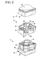
- a culture dish assembly 10 which includes a well insert 12 and a well plate 14 capable of receiving the insert.
- Fig. 1 provides an exploded, perspective view of such an assembly in addition to a lid 16 which is mountable to the well insert 12.
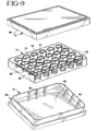
- An alternative embodiment is shown in Fig. 9, where the well plate 14' defines one large well or trough as opposed to a plurality of wells. This type of well plate may be referred to as a feeder tray.
- the insert 12 includes a substantially planar top wall 18 and a peripheral flange 20 extending downwardly from the top wall.
- the top wall conforms in configuration to the upper surface of the well plate, which is rectangular in the preferred embodiment of the invention.
- the flange 20 forms a slightly oblique angle with the top wall 18 to facilitate application of the insert to the well plate.
- the flange 20 has an inside surface 20a and a lower edge 20b; in a preferred embodiment the lower edge 20b is slightly chamfered or beveled toward the inside surface 20a of flange 20.
- a plurality of enclosures 22 are coupled to the top wall 18 and extend downwardly therefrom.
- the enclosures are preferably arranged in rows as shown in the figures. While the insert shown in the drawings includes twenty-four enclosures, other inserts are contemplated including six, twelve, forty-eight and ninety-six enclosures, which are among the standard numbers of such enclosures used in the trade.
- the spacing among enclosures also preferably conforms to trade standards.
- the enclosures are formed integrally with the top wall from a transparent material such as polystyrene. In any event, they are preferably coupled permanently to the top wall, though there may be instances in which it would be desirable for the enclosures to be removable from the top wall.
- Each enclosure includes an upper end 24 defining an upper opening and a lower end 26 defining a bottom opening.
- a radial opening 30 extends through the side wall and a portion of the upper end of each enclosure.
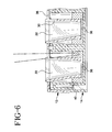
- the side wall includes a substantially vertical flat portion 32 adjoining the radial opening and extending towards the lower end of the enclosure. As discussed below, this substantially vertical portion of the side wall 28 of the enclosure results in a relatively large space between one side of the enclosure and a well wall which opposes this side wall portion.
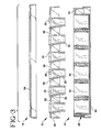
- each enclosure includes an annular end face 34, as shown in Fig. 3.
- a semipermeable, microporous membrane 36 is affixed to this end face, as shown in Figs. 4-6.
- the composition and pore size of the membrane is largely determined by the intended use of the culture dish assembly, as many membranes are known and available to the trade.
- Such membranes may be hydrophobic or hydrophilic, and made from such materials as perforated inert film, hydrated gel, cellulose, track-etched PET, polyacrylonitrile or polytetrafluoroethylene.
- Other microporous membranes could be employed at the discretion of the end user.
- the membrane is applied to the end face 34 using known techniques such as heat sealing or adhesive bonding.
- the assembly 10 may be provided to end users without membranes to allow them to affix the particular membranes that they prefer.
- the upper ends of the enclosures extend above the upper surface of the top wall of the insert 12.
- the upper end faces of the enclosures are substantially C-shaped due to the radial openings therein.
- a plurality of wall openings 38 extend through the top wall of the insert and respectively adjoin the radial openings 30 in the enclosures.
- the wall openings are preferably, though not necessarily rectangular.
- the wall openings and radial openings define a plurality of pipette openings which allow pipette access to selected portions of the well plate, as shown in Fig. 6.
- the well plate 14 is conventional in design, and is preferably made from a transparent material such as polystyrene. It includes a plurality of wells 40 arranged in rows. The numbers of wells and enclosures in the well plate and insert are not critical, but are preferably equal in number. Each of the wells is preferably cylindrical. The wells are joined to each other by rib portions extending between the side walls thereof. In addition, each of the wells shares a common bottom wall 42.
- the well plate 14 further includes a top wall 44 which is integral with the outer surfaces of the wells located along the peripheral portions thereof. A peripheral wall 46 extends downwardly from the top wall 44. It includes an upper portion 46A and a lower portion 46B, with a shoulder or step 48 separating these portions. The upper wall portion includes a pair of chamfered corners 50. Ribs 52 connect selected portions of the wells to the peripheral wall 46.
- the well plate 14 and insert 12 are constructed such that the insert can only be mounted to the well plate in one direction.
- the lid 16 is conventional in construction, and includes a rectangular top wall 54 and a downwardly depending peripheral flange 56 extending at a slightly oblique angle with respect thereto. It is made from a transparent material such as polystyrene. The bottom surface of the top wall of the lid engages the upper ends 24 of the enclosures 22 when the lid is applied to the insert 12.
- the insert 12 may be mounted to a plate 14' defining one large trough or well so that the membranes 36 can be immersed in a common bath.
- the plate 14' includes a stepped peripheral wall 58 and a bottom wall 60. Ribs 61 connect the bottom and peripheral walls, thereby adding strength to the plate.
- the number of ribs 61 may be increased to add rigidity, as known to the art.
- the presence of a plurality of ribs 61 provides a baffle effect within the plate 14', by reducing the movement or turbulence caused within the media of the media as a result of the plate being moved.
- the upper surface of the peripheral wall is engageable with the bottom surface of the top wall 18 of the insert 12.
- the assembly 10 may be provided to end users as shown in Figs. 1-3 and 9. Alternatively, the assemblies may be manufactured and sold with membranes 36 already secured to the enclosures 22. Once the membranes are secured, the insert 12 is ready for use.
- the insert 12 is mounted to the well plate 14 such that the bottom surface of the top wall 18 engages the rim portions of the wells 40, and point contacts are made between the side wall 28 of each enclosure and the inner edge of the upper rim of each well 40.
- the membranes are suspended above the bottom surfaces of the wells, as shown in Figs. 4-5, when the insert is properly mounted.
- the membranes should be one to three millimeters above the upper surface of the bottom wall 42.
- the peripheral flange 20 of the insert 12 overlies the upper portion 46A of the flange of the well plate, and is suspended above the step 48.
- Each enclosure 22 is radially offset with respect to the well in which it is positioned, producing relatively large spaces between the enclosures and the opposing portions of the wells.
- the radial openings adjoin these relatively large spaces.
- these spaces are further enlarged by the irregular configurations of the enclosures, particularly the flat surfaces 32 which border upon them.
- the wall openings 38 in the top wall 18 of the insert are positioned directly above the spaces between the enclosures and the wells. As shown in Fig.
- the offset positions of the wells combined with the flat surfaces of the enclosures and the adjoining radial openings and wall openings greatly facilitate access to the bottom portions of the wells 40 with a pipette (shown in broken lines).
- the lid 16 is mounted to the insert 12 and engages the C-shaped rims of the enclosures. Evaporation from the wells and exposure to airborne contaminants such as dust or bacteria are accordingly minimized.
- the peripheral flange 56 of the lid extends only partially over the peripheral flange 20 of the insert 12. This feature is important in that it allows the lid and insert to be removed from and reapplied to the well plate as a unit, thereby reducing the possibility of contamination. This may be accomplished manually or robotically.
- each enclosure 22 of insert 12 is radially offset with respect to the well within well plate 14 in which it is positioned some wicking occurs between the side wall 28 of enclosure 22 and the well 40 of the well plate 14, therefore it is preferred that the outside of sidewall 28 in the proximity of the lower end 26 have a plurality of concentric rings 26a on side wall 28; these concentric rings 26a inhibit wicking of the media between the sidewall 28 of insert 12 and the well 40 of the well plate 14, see Figure 2.
- Fig. 9 For those procedures or tests which require immersion of the membranes in a common bath, the assembly of Fig. 9 may be employed.
- the membranes secured to the enclosures of the insert 12 When mounted to the well plate 14' shown in this figure, the membranes secured to the enclosures of the insert 12 will be suspended above the bottom wall 60 of the well plate.
- experiments can be observed without removing the lid or any other components as they are all substantially transparent.
Abstract
Description
Claims (10)
- A culture dish assembly comprising:a well plate defining at least one well;an insert including a top wall and a plurality of enclosures coupled to said top wall, each of said enclosures including an upper end defining an upper opening, a lower end defining a bottom opening, a side wall connecting said upper and lower ends, a semi-permeable membrane mounted to said lower end and covering said bottom opening, a plurality of wall openings in said top wall, each of said wall openings adjoining one of said enclosures, each of said enclosures including a radial opening extending through said side wall and said upper end, each of said side walls including a substantially vertical portion adjoining said radial opening and extending towards said lower end, said radial openings each adjoining one of said wall openings and defining therewith a plurality of pipette openings, said insert being mountable to said well plate such that at least one of said enclosures is positioned within said well, and further, wherein said well plate includes a plurality of substantially cylindrical wells, said insert being mountable to said well plate such that each of said enclosures is positioned within one of said wells and radially offset with respect to said well, and said wall openings are in registration with said wells.
- A culture dish assembly as described in Claim 1, wherein said side walls of said enclosures are generally frustoconical, said vertical portions of said side walls including substantially flat exterior surfaces.
- A culture dish assembly as described in Claim I including a lid mountable to said insert, said insert including a peripheral flange extending downwardly from said top wall, said lid including a peripheral flange of lesser height than said peripheral flange of said insert, said peripheral flange of said lid being positionable about an upper portion of said peripheral flange of said insert.
- A culture dish assembly as described in Claim 3, wherein said well plate includes a peripheral wall including a lower portion, an upper portion, and a step formed between said upper and lower portions, said insert being mountable to said well plate such that said peripheral flange of said insert is suspended above said step.
- A culture dish assembly as described in Claim 1, wherein said well plate includes a plurality of rows of substantially cylindrical wells, said insert being mountable to said well plate such that each of said enclosures is positioned within one of said wells and radially offset with respect to said well, and said wall openings are in registration with said wells.
- An insert for a culture dish assembly, comprising:a top wall including at least one row of wall openings, anda plurality of enclosures coupled to said top wall and respectively adjoining said wall openings, each of said enclosures including an upper end defining an upper opening, a lower end defining a bottom opening, a side wall connecting said upper and lower ends, a radial opening extending through said side wall and a portion of said upper end, each of said radial openings adjoining one of said wall openings, each of said side walls of said enclosures including a substantially vertical portion adjoining said radial opening and extending towards said lower end.
- An insert as described in Claim 6, wherein each of said side walls is generally frustoconical, and wherein each of said enclosures includes a microporous membrane secured to said lower end thereof and covering said bottom opening.
- An insert as described in Claim 6 including a peripheral flange extending downwardly from said top wall.
- A culture dish assembly comprising:a well plate defining a plurality of wells;an insert including a top wall, a peripheral flange extending downwardly from said top wall, said peripheral flange including an upper portion and a lower portion, and a plurality of enclosures coupled to said top wall, each of said enclosures including an upper end defining an upper opening, a lower end defining a bottom opening, a side wall connecting said upper and lower ends, a semi-permeable membrane mounted to said lower end and covering said bottom opening, a plurality of wall openings in said top wall, each of said wall openings adjoining one of said enclosures, each of said enclosures including a radial opening extending through said side wall and said upper end, each of said side walls including a substantially vertical portion adjoining said radial opening and extending towards said lower end, said radial openings each adjoining one of said wall openings and defining therewith a plurality of pipette openings, said insert being mountable to said well plate such that said enclosures are respectively positioned within and radially offset with respect to said wells, and a lid including a top wall and a downwardly depending peripheral flange, said lid being mountable to said insert such that said top wall of said lid engages said upper ends of said enclosures, said peripheral flange of said lid overlies said upper portion of said peripheral flange of said insert and said lower portion of said peripheral flange of said insert is accessible beneath said peripheral flange of said lid, thereby allowing said insert and lid to be removed from or applied to said well plate as a unit.
- A culture dish assembly as described in Claim 9, wherein each of said wells is substantially cylindrical, each of said enclosures is substantially frustoconical, each of said side walls of said enclosures includes a substantially flat, vertical portion adjoining said radial opening and extending towards said lower end.
Applications Claiming Priority (2)
| Application Number | Priority Date | Filing Date | Title |
|---|---|---|---|
| US926562 | 1997-09-10 | ||
| US08/926,562 US5801055A (en) | 1997-09-10 | 1997-09-10 | Multi-well culture dish assembly |
Publications (3)
| Publication Number | Publication Date |
|---|---|
| EP0902084A2 true EP0902084A2 (en) | 1999-03-17 |
| EP0902084A3 EP0902084A3 (en) | 2004-02-11 |
| EP0902084B1 EP0902084B1 (en) | 2005-08-10 |
Family
ID=25453379
Family Applications (1)
| Application Number | Title | Priority Date | Filing Date |
|---|---|---|---|
| EP98306971A Expired - Lifetime EP0902084B1 (en) | 1997-09-10 | 1998-09-01 | Multi-well culture dish assembly |
Country Status (7)
| Country | Link |
|---|---|
| US (1) | US5801055A (en) |
| EP (1) | EP0902084B1 (en) |
| JP (1) | JP4312855B2 (en) |
| AT (1) | ATE301706T1 (en) |
| CA (1) | CA2245030A1 (en) |
| DE (1) | DE69831115T2 (en) |
| ES (1) | ES2246064T3 (en) |
Cited By (2)
| Publication number | Priority date | Publication date | Assignee | Title |
|---|---|---|---|---|
| DE10117723A1 (en) * | 2001-04-09 | 2002-10-17 | Evotec Ag | Carrier for biological or synthetic samples has a sample holding plate with reservoirs and a dosing plate with projections, fitted with membranes, of an optically transparent material with trouble-free light beam transparency |
| DE102004046724B3 (en) * | 2004-09-27 | 2006-02-02 | Zell-Kontakt Gmbh | Reaction container, comprises outlet surrounding reaction surface and provides supporting cover unit in order to form reaction chamber by arranging plane central area of cover unit in preset distance to surface |
Families Citing this family (102)
| Publication number | Priority date | Publication date | Assignee | Title |
|---|---|---|---|---|
| US6258326B1 (en) | 1997-09-20 | 2001-07-10 | Ljl Biosystems, Inc. | Sample holders with reference fiducials |
| US6297018B1 (en) | 1998-04-17 | 2001-10-02 | Ljl Biosystems, Inc. | Methods and apparatus for detecting nucleic acid polymorphisms |
| US6136273A (en) * | 1998-11-18 | 2000-10-24 | Matrix Technologies Corporation | Closure device for laboratory receptacles |
| JP2003517581A (en) * | 1999-02-16 | 2003-05-27 | ピーイー コーポレイション (エヌワイ) | Bead dispersion system |
| US6558628B1 (en) * | 1999-03-05 | 2003-05-06 | Specialty Silicone Products, Inc. | Compartment cover, kit and method for forming the same |
| US6399394B1 (en) | 1999-06-30 | 2002-06-04 | Agilent Technologies, Inc. | Testing multiple fluid samples with multiple biopolymer arrays |
| US6448030B1 (en) | 2000-02-18 | 2002-09-10 | University Of Nevada-Las Vegas | Method for predicting the efficacy of anti-cancer drugs |
| AU2002249778A1 (en) | 2000-11-17 | 2002-08-12 | Thermogenic Imaging, Inc. | Apparatus and methods for infrared calorimetric measurements |
| US20020132360A1 (en) | 2000-11-17 | 2002-09-19 | Flir Systems Boston, Inc. | Apparatus and methods for infrared calorimetric measurements |
| US7326385B2 (en) * | 2001-05-30 | 2008-02-05 | Biolex Therapeutics, Inc. | Plate and method for high throughput screening |
| US7118909B2 (en) * | 2001-05-30 | 2006-10-10 | Gevaert Matthew R | Apparatus and method for biomaterial assay |
| DE60215377T2 (en) * | 2001-06-14 | 2007-08-23 | Millipore Corp., Billerica | The multiwell cell growth apparatus |
| EP1397212B1 (en) * | 2001-06-14 | 2010-12-08 | Millipore Corporation | Positioning pins for multiwell test apparatus |
| US7282362B2 (en) * | 2001-06-14 | 2007-10-16 | Millipore Corporation | Tray with protrusions |
| ES2606538T3 (en) * | 2001-06-14 | 2017-03-24 | Emd Millipore Corporation | Feed tray for test apparatus equipped with multiple wells |
| US7135148B2 (en) * | 2001-06-14 | 2006-11-14 | Millipore Corporation | Access holes for a multiwell filter plate for multiwell test apparatus |
| JP3680014B2 (en) * | 2001-08-20 | 2005-08-10 | アロカ株式会社 | Sample processing container |
| US7666661B2 (en) | 2001-08-27 | 2010-02-23 | Platypus Technologies, Llc | Substrates, devices, and methods for quantitative liquid crystal assays |
| EP1291074A1 (en) * | 2001-09-07 | 2003-03-12 | F. Hoffmann-La Roche Ag | Reaction block for parallel synthetic chemistry and vessel therefor |
| MXPA04001815A (en) * | 2001-09-20 | 2005-03-07 | Dimensional Pharm Inc | Conductive microtiter plate. |
| DE10160975A1 (en) * | 2001-12-10 | 2003-06-18 | Univ Schiller Jena | Sample plate for use in dialysis systems |
| US6723236B2 (en) * | 2002-03-19 | 2004-04-20 | Waters Investments Limited | Device for solid phase extraction and method for purifying samples prior to analysis |
| WO2003097237A2 (en) * | 2002-05-13 | 2003-11-27 | Becton, Dickinson, And Company | Protease inhibitor sample collection system |
| US6943009B2 (en) * | 2002-05-15 | 2005-09-13 | Corning Incorporated | Multi-well assembly for growing cultures in-vitro |
| US8268614B2 (en) * | 2002-05-22 | 2012-09-18 | Platypus Technologies, Llc | Method for assaying cell movement |
| US7537936B2 (en) * | 2002-05-31 | 2009-05-26 | Agilent Technologies, Inc. | Method of testing multiple fluid samples with multiple biopolymer arrays |
| EP1371966A1 (en) * | 2002-06-14 | 2003-12-17 | Stiftung Für Diagnostische Forschung | A cuvette for a reader device for assaying substances using the evanescence field method |
| US7732127B2 (en) * | 2002-12-20 | 2010-06-08 | Acea Biosciences, Inc. | Dynamic monitoring of cell adhesion and spreading using the RT-CES system |
| US7560269B2 (en) * | 2002-12-20 | 2009-07-14 | Acea Biosciences, Inc. | Real time electronic cell sensing system and applications for cytotoxicity profiling and compound assays |
| CN100487133C (en) * | 2002-07-20 | 2009-05-13 | 艾森生物(杭州)有限公司 | Testing apparatuses and methods based impedance |
| US8263375B2 (en) | 2002-12-20 | 2012-09-11 | Acea Biosciences | Dynamic monitoring of activation of G-protein coupled receptor (GPCR) and receptor tyrosine kinase (RTK) in living cells using real-time microelectronic cell sensing technology |
| US8206903B2 (en) | 2002-12-20 | 2012-06-26 | Acea Biosciences | Device and method for electroporation-based delivery of molecules into cells and dynamic monitoring of cell responses |
| US7468255B2 (en) * | 2002-12-20 | 2008-12-23 | Acea Biosciences | Method for assaying for natural killer, cytotoxic T-lymphocyte and neutrophil-mediated killing of target cells using real-time microelectronic cell sensing technology |
| US7470533B2 (en) | 2002-12-20 | 2008-12-30 | Acea Biosciences | Impedance based devices and methods for use in assays |
| US6939709B2 (en) * | 2002-08-30 | 2005-09-06 | Becton, Dickinson And Company | Multi-well device |
| DE10240787B4 (en) * | 2002-08-30 | 2004-07-22 | Oxyphen Ag | Cell culture insert |
| US7128878B2 (en) * | 2002-10-04 | 2006-10-31 | Becton, Dickinson And Company | Multiwell plate |
| CA2501196A1 (en) | 2002-10-10 | 2004-04-22 | Becton, Dickinson And Company | Sample collection system with caspase inhibitor |
| US20040086869A1 (en) * | 2002-10-31 | 2004-05-06 | Schembri Carol T. | Device having multiple molecular arrays |
| EP1560651A1 (en) * | 2002-11-12 | 2005-08-10 | Millipore Corporation | Evaporation control device for multiwell plates |
| US10215748B2 (en) | 2002-12-20 | 2019-02-26 | Acea Biosciences, Inc. | Using impedance-based cell response profiling to identify putative inhibitors for oncogene addicted targets or pathways |
| US10551371B2 (en) | 2003-11-10 | 2020-02-04 | Acea Biosciences, Inc. | System and method for monitoring cardiomyocyte beating, viability and morphology and for screening for pharmacological agents which may induce cardiotoxicity or modulate cardiomyocyte function |
| US10539523B2 (en) | 2002-12-20 | 2020-01-21 | Acea Biosciences, Inc. | System and method for monitoring cardiomyocyte beating, viability, morphology, and electrophysiological properties |
| US11346797B2 (en) | 2002-12-20 | 2022-05-31 | Agilent Technologies, Inc. | System and method for monitoring cardiomyocyte beating, viability, morphology and electrophysiological properties |
| ES2241427B2 (en) * | 2003-03-24 | 2007-02-16 | Universidad De Alicante | ANTI-INHIBITORY CLOSURE SYSTEM. |
| CA2550274A1 (en) * | 2003-11-12 | 2005-05-26 | Acea Biosciences, Inc. | Real time electronic cell sensing systems and applications for cell-based assays |
| US20050124965A1 (en) * | 2003-12-08 | 2005-06-09 | Becton, Dickinson And Company | Phosphatase inhibitor sample collection system |
| US20050265902A1 (en) * | 2004-05-27 | 2005-12-01 | Ellen Chen | Industry standard multi-well plates with increased capacity and efficiency per well |
| AT500473B8 (en) * | 2004-06-28 | 2007-02-15 | Markus Mag Voelp | INCUBATOR |
| JP4543212B2 (en) * | 2004-08-20 | 2010-09-15 | 独立行政法人産業技術総合研究所 | Cell culture container and culture method |
| US7968061B2 (en) * | 2004-10-18 | 2011-06-28 | Becton, Dickinson And Company | Microplate with dialysis membrane |
| WO2006124672A2 (en) * | 2005-05-12 | 2006-11-23 | University Of Alabama In Huntsville | Apparatus and method for incubating cell cultures |
| EP1893738B1 (en) * | 2005-06-10 | 2018-12-05 | Nunc A/S | Culture insert carrier, culture insert and culture insert system |
| US20060286003A1 (en) | 2005-06-16 | 2006-12-21 | Desilets Kenneth G | Multi-well filter plate with shifted wells and U-bottom receiver plate |
| EP1924680A2 (en) * | 2005-09-16 | 2008-05-28 | Becton, Dickinson & Company | Scaffold carrier cartridge |
| US7922672B2 (en) * | 2006-06-08 | 2011-04-12 | Lincoln Diagnostics, Inc. | Skin testing-device system |
| US8041515B2 (en) * | 2006-09-20 | 2011-10-18 | Acea Biosciences, Inc. | Use of impedance-based cytological profiling to classify cellular response profiles upon exposure to biologically active agents |
| US9938641B2 (en) * | 2006-12-18 | 2018-04-10 | Fluidigm Corporation | Selection of aptamers based on geometry |
| WO2008094744A1 (en) * | 2007-01-26 | 2008-08-07 | Kalypsys, Inc. | Multi-well plate lid with protective skirt |
| EP2193365A4 (en) * | 2007-08-20 | 2015-05-13 | Platypus Technologies Llc | Improved devices for cell assays |
| CA2723223C (en) | 2008-05-05 | 2017-06-06 | Acea Biosciences, Inc. | Label-free monitoring of excitation-contraction coupling and excitable cells using impedance based systems with millisecond time resolution |
| US8591840B2 (en) * | 2009-01-23 | 2013-11-26 | Eppendorf Ag | Carrier for pipette tips |
| FR2942239B1 (en) * | 2009-02-18 | 2013-07-26 | Oreal | CELL OR TISSUE CULTURE DEVICE AND ASSOCIATED ASSEMBLY |
| FR2942240B1 (en) * | 2009-02-18 | 2011-03-18 | Oreal | CELL OR TISSUE CULTURE DEVICE WITH ADAPTER AND ASSOCIATED CELL OR TISSUE CULTURE ASSEMBLY |
| EP2411501B1 (en) * | 2009-03-26 | 2015-08-05 | Agency for Science, Technology and Research | Apparatus for cell or tissue culture |
| TWI394832B (en) * | 2009-04-24 | 2013-05-01 | Univ Chang Gung | Colloidal unit preparation tool and method thereof, biological sample culture device |
| CN101962613A (en) * | 2009-07-24 | 2011-02-02 | 无锡耐思生物科技有限公司 | 96-pore cell culture plate without edge effect |
| FR2950359B1 (en) * | 2009-09-23 | 2011-12-02 | Univ Compiegne Tech | FILTRATION DEVICE AND SYSTEM |
| WO2011146531A1 (en) | 2010-05-18 | 2011-11-24 | Acea Biosciences, Inc | Data analysis of impedance-based cardiomyocyte-beating signals as detected on real-time cell analysis (rtca) cardio instruments |
| DE202011003049U1 (en) * | 2011-02-22 | 2011-04-28 | Sabeu Kunststoffwerk Northeim Gmbh | Use for cell cultures |
| US9200246B2 (en) * | 2011-12-01 | 2015-12-01 | Acea Biosciences, Inc. | Co-culture device assembly |
| JP5610312B2 (en) * | 2011-12-22 | 2014-10-22 | 株式会社日立製作所 | Packaging container |
| US20130281323A1 (en) * | 2012-04-19 | 2013-10-24 | Elizabeth Tran | Device and method for cell-exclusion patterning |
| JP2014003922A (en) * | 2012-06-22 | 2014-01-16 | Sumitomo Bakelite Co Ltd | Positioning appliance |
| US9573128B1 (en) | 2012-09-06 | 2017-02-21 | SciKon Innovation, Inc. | Fluidics device allowing fluid flow between a plurality of wells |
| JP5891310B2 (en) * | 2012-09-26 | 2016-03-22 | 株式会社日立製作所 | Cell culture container and cell culture apparatus using the same |
| JP2014132869A (en) * | 2013-01-11 | 2014-07-24 | Sumitomo Bakelite Co Ltd | Cell culture vessel |
| USD767783S1 (en) * | 2013-08-23 | 2016-09-27 | SciKon Innovation, Inc. | Assay tray assembly |
| USD766455S1 (en) * | 2014-04-11 | 2016-09-13 | Marvin Smollar | Allergy testing tray |
| NL2012922B1 (en) * | 2014-05-30 | 2016-06-09 | Ccm Beheer Bv | Container for culturing organisms, method for monitoring the culturing of organisms inside said container, and monitoring system. |
| JP2016077186A (en) * | 2014-10-14 | 2016-05-16 | 大日本印刷株式会社 | Culture container and lower container thereof |
| US10035145B2 (en) | 2014-12-02 | 2018-07-31 | SciKon Innovation, Inc. | Piston assembly and related systems for use with a fluidics device |
| JP2018512171A (en) * | 2015-03-23 | 2018-05-17 | シコン イノベーション,インク. | Methods and associated systems for use with fluidic devices |
| GB2539935A (en) * | 2015-07-01 | 2017-01-04 | Insphero Ag | Device for propagating microtissues |
| USD767163S1 (en) * | 2015-11-03 | 2016-09-20 | Timothy Schimmel | Culture dish |
| USD767160S1 (en) * | 2015-11-03 | 2016-09-20 | Timothy Schimmel | Culture dish |
| USD767164S1 (en) * | 2015-11-03 | 2016-09-20 | Timothy Schimmel | Culture dish |
| USD767161S1 (en) * | 2015-11-03 | 2016-09-20 | Timothy Schimmel | Culture dish |
| USD767162S1 (en) * | 2015-11-03 | 2016-09-20 | Timothy Schimmel | Culture dish |
| USD814654S1 (en) * | 2016-01-27 | 2018-04-03 | Phd Preventative Health Care And Diagnostics, Inc. | Medical mixing tray |
| CN109070088B (en) * | 2016-04-14 | 2022-09-13 | 简·探针公司 | Assembly for storing sample processing consumables, sample processing instrument and method |
| WO2018009767A1 (en) * | 2016-07-07 | 2018-01-11 | University Of Maryland, Baltimore | Inverted culture plate system for cellular co-culture |
| GB201614116D0 (en) | 2016-08-18 | 2016-10-05 | Vib Vzw And Univ Gent | Netwell assay plate system |
| USD840053S1 (en) * | 2017-01-25 | 2019-02-05 | Heathrow Scientific Llc | Test tube holding device |
| WO2018161063A1 (en) | 2017-03-03 | 2018-09-07 | Acea Biosciences, Inc. | METHODS AND SYSTEMS FOR FUNCTIONAL MATURATION OF iPSC AND ESC DERIVED CARDIOMYOCYTES |
| WO2019114996A1 (en) * | 2017-12-15 | 2019-06-20 | Technische Universität Ilmenau | Microbioreactor assembly |
| KR102105299B1 (en) * | 2019-04-02 | 2020-04-29 | 주식회사 엠케이바이오텍 | an embryo culture dish capable of an individual culturing |
| USD941488S1 (en) | 2020-02-07 | 2022-01-18 | Agilent Technologies, Inc. | Instrument for analyzing biological cells |
| WO2022099376A1 (en) * | 2020-11-13 | 2022-05-19 | University Of South Australia | Organoid culture platform |
| EP4015619A1 (en) * | 2020-12-17 | 2022-06-22 | Leica Microsystems CMS GmbH | Microplate assembly and method for transferring sample by means of a microplate assembly |
| DE102021107590A1 (en) | 2021-03-25 | 2022-09-29 | Heinrich-Heine-Universität Düsseldorf | Device for efficient medium change in microtiter plates |
| JP1712510S (en) * | 2021-11-30 | 2022-04-13 | Cell observation container |
Citations (6)
| Publication number | Priority date | Publication date | Assignee | Title |
|---|---|---|---|---|
| US4495289A (en) * | 1981-03-17 | 1985-01-22 | Data Packaging Corporation | Tissue culture cluster dish |
| US4871674A (en) * | 1987-10-12 | 1989-10-03 | Kurashiki Boseki Kabushiki Kaisha | Culture cell |
| US5026649A (en) * | 1986-03-20 | 1991-06-25 | Costar Corporation | Apparatus for growing tissue cultures in vitro |
| EP0590513A1 (en) * | 1992-09-28 | 1994-04-06 | Becton, Dickinson and Company | Cell culture insert |
| US5554536A (en) * | 1995-01-05 | 1996-09-10 | Millipore Investment Holdings Limited | Biological analysis device having improved contamination prevention |
| EP0790300A2 (en) * | 1996-02-15 | 1997-08-20 | Becton, Dickinson and Company | Culture vessel and assembly |
Family Cites Families (5)
| Publication number | Priority date | Publication date | Assignee | Title |
|---|---|---|---|---|
| US4407943A (en) * | 1976-12-16 | 1983-10-04 | Millipore Corporation | Immobilized antibody or antigen for immunoassay |
| US5366893A (en) * | 1993-01-13 | 1994-11-22 | Becton, Dickinson And Company | Culture vessel |
| US5462874A (en) * | 1993-06-23 | 1995-10-31 | Wolf; Martin L. | Dialyzed multiple well tissue culture plate |
| US5487872A (en) * | 1994-04-15 | 1996-01-30 | Molecular Device Corporation | Ultraviolet radiation transparent multi-assay plates |
| US5534227A (en) * | 1995-06-05 | 1996-07-09 | Becton, Dickinson And Company | Thermoform dish insert |
-
1997
- 1997-09-10 US US08/926,562 patent/US5801055A/en not_active Expired - Lifetime
-
1998
- 1998-08-13 CA CA002245030A patent/CA2245030A1/en not_active Abandoned
- 1998-09-01 DE DE69831115T patent/DE69831115T2/en not_active Expired - Lifetime
- 1998-09-01 EP EP98306971A patent/EP0902084B1/en not_active Expired - Lifetime
- 1998-09-01 AT AT98306971T patent/ATE301706T1/en active
- 1998-09-01 ES ES98306971T patent/ES2246064T3/en not_active Expired - Lifetime
- 1998-09-10 JP JP25721698A patent/JP4312855B2/en not_active Expired - Fee Related
Patent Citations (6)
| Publication number | Priority date | Publication date | Assignee | Title |
|---|---|---|---|---|
| US4495289A (en) * | 1981-03-17 | 1985-01-22 | Data Packaging Corporation | Tissue culture cluster dish |
| US5026649A (en) * | 1986-03-20 | 1991-06-25 | Costar Corporation | Apparatus for growing tissue cultures in vitro |
| US4871674A (en) * | 1987-10-12 | 1989-10-03 | Kurashiki Boseki Kabushiki Kaisha | Culture cell |
| EP0590513A1 (en) * | 1992-09-28 | 1994-04-06 | Becton, Dickinson and Company | Cell culture insert |
| US5554536A (en) * | 1995-01-05 | 1996-09-10 | Millipore Investment Holdings Limited | Biological analysis device having improved contamination prevention |
| EP0790300A2 (en) * | 1996-02-15 | 1997-08-20 | Becton, Dickinson and Company | Culture vessel and assembly |
Cited By (2)
| Publication number | Priority date | Publication date | Assignee | Title |
|---|---|---|---|---|
| DE10117723A1 (en) * | 2001-04-09 | 2002-10-17 | Evotec Ag | Carrier for biological or synthetic samples has a sample holding plate with reservoirs and a dosing plate with projections, fitted with membranes, of an optically transparent material with trouble-free light beam transparency |
| DE102004046724B3 (en) * | 2004-09-27 | 2006-02-02 | Zell-Kontakt Gmbh | Reaction container, comprises outlet surrounding reaction surface and provides supporting cover unit in order to form reaction chamber by arranging plane central area of cover unit in preset distance to surface |
Also Published As
| Publication number | Publication date |
|---|---|
| CA2245030A1 (en) | 1999-03-10 |
| EP0902084A3 (en) | 2004-02-11 |
| US5801055A (en) | 1998-09-01 |
| ES2246064T3 (en) | 2006-02-01 |
| JPH11137243A (en) | 1999-05-25 |
| DE69831115D1 (en) | 2005-09-15 |
| ATE301706T1 (en) | 2005-08-15 |
| DE69831115T2 (en) | 2006-06-01 |
| EP0902084B1 (en) | 2005-08-10 |
| JP4312855B2 (en) | 2009-08-12 |
Similar Documents
| Publication | Publication Date | Title |
|---|---|---|
| EP0902084B1 (en) | Multi-well culture dish assembly | |
| EP0606651B1 (en) | Culture vessel | |
| EP0747476B1 (en) | Thermoform dish insert | |
| EP0800571B1 (en) | Biological analysis device having improved contamination prevention | |
| EP0183973B1 (en) | Multiwell tissue culture assembly with features for reduced media evaporation | |
| EP0590513B1 (en) | Cell culture insert | |
| EP1893738B1 (en) | Culture insert carrier, culture insert and culture insert system | |
| JP4108816B2 (en) | Cultivation container assembly, lid used therefor, and cell culture method using the same | |
| JP4126109B2 (en) | Cultivation container assembly, lid used therefor, and cell culture method using the same | |
| EP1394247B1 (en) | Multi-well device | |
| ES2294244T3 (en) | MICROPLACA WITH BOTTOM COVER OF PROTECTIVE TRAY. | |
| US5795775A (en) | Culture vessel and assembly | |
| EP0638640B1 (en) | Culture vessel | |
| EP0790300B1 (en) | Culture vessel and assembly | |
| JPS60102184A (en) | Culture flask | |
| EP1069181A2 (en) | Closure assembly for multiwell vessel |
Legal Events
| Date | Code | Title | Description |
|---|---|---|---|
| PUAI | Public reference made under article 153(3) epc to a published international application that has entered the european phase |
Free format text: ORIGINAL CODE: 0009012 |
|
| AK | Designated contracting states |
Kind code of ref document: A2 Designated state(s): AT BE CH CY DE DK ES FI FR GB GR IE IT LI LU MC NL PT SE |
|
| AX | Request for extension of the european patent |
Free format text: AL;LT;LV;MK;RO;SI |
|
| PUAL | Search report despatched |
Free format text: ORIGINAL CODE: 0009013 |
|
| AK | Designated contracting states |
Kind code of ref document: A3 Designated state(s): AT BE CH CY DE DK ES FI FR GB GR IE IT LI LU MC NL PT SE |
|
| AX | Request for extension of the european patent |
Extension state: AL LT LV MK RO SI |
|
| 17P | Request for examination filed |
Effective date: 20040809 |
|
| AKX | Designation fees paid |
Designated state(s): AT CH DE ES FR GB IT LI |
|
| GRAP | Despatch of communication of intention to grant a patent |
Free format text: ORIGINAL CODE: EPIDOSNIGR1 |
|
| GRAS | Grant fee paid |
Free format text: ORIGINAL CODE: EPIDOSNIGR3 |
|
| GRAA | (expected) grant |
Free format text: ORIGINAL CODE: 0009210 |
|
| AK | Designated contracting states |
Kind code of ref document: B1 Designated state(s): AT CH DE ES FR GB IT LI |
|
| REG | Reference to a national code |
Ref country code: GB Ref legal event code: FG4D |
|
| REG | Reference to a national code |
Ref country code: CH Ref legal event code: EP |
|
| PG25 | Lapsed in a contracting state [announced via postgrant information from national office to epo] |
Ref country code: IT Free format text: LAPSE BECAUSE OF NON-PAYMENT OF DUE FEES Effective date: 20050901 |
|
| REF | Corresponds to: |
Ref document number: 69831115 Country of ref document: DE Date of ref document: 20050915 Kind code of ref document: P |
|
| PG25 | Lapsed in a contracting state [announced via postgrant information from national office to epo] |
Ref country code: LI Free format text: LAPSE BECAUSE OF NON-PAYMENT OF DUE FEES Effective date: 20050930 Ref country code: CH Free format text: LAPSE BECAUSE OF NON-PAYMENT OF DUE FEES Effective date: 20050930 |
|
| PG25 | Lapsed in a contracting state [announced via postgrant information from national office to epo] |
Ref country code: GB Free format text: LAPSE BECAUSE OF NON-PAYMENT OF DUE FEES Effective date: 20051110 |
|
| REG | Reference to a national code |
Ref country code: CH Ref legal event code: NV Representative=s name: RITSCHER & PARTNER AG |
|
| REG | Reference to a national code |
Ref country code: ES Ref legal event code: FG2A Ref document number: 2246064 Country of ref document: ES Kind code of ref document: T3 |
|
| PG25 | Lapsed in a contracting state [announced via postgrant information from national office to epo] |
Ref country code: DE Free format text: LAPSE BECAUSE OF NON-PAYMENT OF DUE FEES Effective date: 20060401 |
|
| ET | Fr: translation filed | ||
| REG | Reference to a national code |
Ref country code: CH Ref legal event code: PL |
|
| PLBE | No opposition filed within time limit |
Free format text: ORIGINAL CODE: 0009261 |
|
| STAA | Information on the status of an ep patent application or granted ep patent |
Free format text: STATUS: NO OPPOSITION FILED WITHIN TIME LIMIT |
|
| 26N | No opposition filed |
Effective date: 20060511 |
|
| GBPC | Gb: european patent ceased through non-payment of renewal fee |
Effective date: 20051110 |
|
| PG25 | Lapsed in a contracting state [announced via postgrant information from national office to epo] |
Ref country code: FR Free format text: LAPSE BECAUSE OF NON-PAYMENT OF DUE FEES Effective date: 20060731 |
|
| REG | Reference to a national code |
Ref country code: GB Ref legal event code: 728V |
|
| REG | Reference to a national code |
Ref country code: FR Ref legal event code: ST Effective date: 20060731 |
|
| REG | Reference to a national code |
Ref country code: GB Ref legal event code: 728Y |
|
| PG25 | Lapsed in a contracting state [announced via postgrant information from national office to epo] |
Ref country code: FR Free format text: LAPSE BECAUSE OF NON-PAYMENT OF DUE FEES Effective date: 20050930 |
|
| REG | Reference to a national code |
Ref country code: ES Ref legal event code: PC2A Owner name: CORNING INCORPORATED Effective date: 20130208 |
|
| REG | Reference to a national code |
Ref country code: DE Ref legal event code: R081 Ref document number: 69831115 Country of ref document: DE Owner name: CORNING INCORPORATED, CORNING, US Free format text: FORMER OWNER: BECTON, DICKINSON AND CO., FRANKLIN LAKES, N.J., US Effective date: 20130128 Ref country code: DE Ref legal event code: R081 Ref document number: 69831115 Country of ref document: DE Owner name: CORNING INCORPORATED, US Free format text: FORMER OWNER: BECTON, DICKINSON AND CO., FRANKLIN LAKES, US Effective date: 20130128 |
|
| REG | Reference to a national code |
Ref country code: GB Ref legal event code: 732E Free format text: REGISTERED BETWEEN 20130321 AND 20130327 |
|
| PGFP | Annual fee paid to national office [announced via postgrant information from national office to epo] |
Ref country code: DE Payment date: 20130927 Year of fee payment: 16 Ref country code: ES Payment date: 20130926 Year of fee payment: 16 Ref country code: AT Payment date: 20130821 Year of fee payment: 16 |
|
| PGFP | Annual fee paid to national office [announced via postgrant information from national office to epo] |
Ref country code: GB Payment date: 20130927 Year of fee payment: 16 |
|
| REG | Reference to a national code |
Ref country code: AT Ref legal event code: PC Ref document number: 301706 Country of ref document: AT Kind code of ref document: T Owner name: CORNING INCORPORATED, US Effective date: 20131106 |
|
| REG | Reference to a national code |
Ref country code: DE Ref legal event code: R119 Ref document number: 69831115 Country of ref document: DE |
|
| REG | Reference to a national code |
Ref country code: AT Ref legal event code: MM01 Ref document number: 301706 Country of ref document: AT Kind code of ref document: T Effective date: 20140901 |
|
| GBPC | Gb: european patent ceased through non-payment of renewal fee |
Effective date: 20140901 |
|
| PG25 | Lapsed in a contracting state [announced via postgrant information from national office to epo] |
Ref country code: DE Free format text: LAPSE BECAUSE OF NON-PAYMENT OF DUE FEES Effective date: 20150401 Ref country code: GB Free format text: LAPSE BECAUSE OF NON-PAYMENT OF DUE FEES Effective date: 20140901 |
|
| PG25 | Lapsed in a contracting state [announced via postgrant information from national office to epo] |
Ref country code: AT Free format text: LAPSE BECAUSE OF NON-PAYMENT OF DUE FEES Effective date: 20140901 |
|
| REG | Reference to a national code |
Ref country code: ES Ref legal event code: FD2A Effective date: 20151027 |
|
| PG25 | Lapsed in a contracting state [announced via postgrant information from national office to epo] |
Ref country code: ES Free format text: LAPSE BECAUSE OF NON-PAYMENT OF DUE FEES Effective date: 20140902 |