EP0896682B1 - Formed ultra-flexible retroreflective cube-corner composite sheeting with target optical properties and method for making same - Google Patents
Formed ultra-flexible retroreflective cube-corner composite sheeting with target optical properties and method for making same Download PDFInfo
- Publication number
- EP0896682B1 EP0896682B1 EP96930653A EP96930653A EP0896682B1 EP 0896682 B1 EP0896682 B1 EP 0896682B1 EP 96930653 A EP96930653 A EP 96930653A EP 96930653 A EP96930653 A EP 96930653A EP 0896682 B1 EP0896682 B1 EP 0896682B1
- Authority
- EP
- European Patent Office
- Prior art keywords
- cube
- retroreflective
- corner elements
- sheeting
- corner
- Prior art date
- Legal status (The legal status is an assumption and is not a legal conclusion. Google has not performed a legal analysis and makes no representation as to the accuracy of the status listed.)
- Expired - Lifetime
Links
Images


Classifications
-
- G—PHYSICS
- G02—OPTICS
- G02B—OPTICAL ELEMENTS, SYSTEMS OR APPARATUS
- G02B5/00—Optical elements other than lenses
- G02B5/12—Reflex reflectors
- G02B5/122—Reflex reflectors cube corner, trihedral or triple reflector type
- G02B5/124—Reflex reflectors cube corner, trihedral or triple reflector type plural reflecting elements forming part of a unitary plate or sheet
-
- Y—GENERAL TAGGING OF NEW TECHNOLOGICAL DEVELOPMENTS; GENERAL TAGGING OF CROSS-SECTIONAL TECHNOLOGIES SPANNING OVER SEVERAL SECTIONS OF THE IPC; TECHNICAL SUBJECTS COVERED BY FORMER USPC CROSS-REFERENCE ART COLLECTIONS [XRACs] AND DIGESTS
- Y10—TECHNICAL SUBJECTS COVERED BY FORMER USPC
- Y10T—TECHNICAL SUBJECTS COVERED BY FORMER US CLASSIFICATION
- Y10T156/00—Adhesive bonding and miscellaneous chemical manufacture
- Y10T156/10—Methods of surface bonding and/or assembly therefor
- Y10T156/1002—Methods of surface bonding and/or assembly therefor with permanent bending or reshaping or surface deformation of self sustaining lamina
- Y10T156/1007—Running or continuous length work
- Y10T156/1023—Surface deformation only [e.g., embossing]
-
- Y—GENERAL TAGGING OF NEW TECHNOLOGICAL DEVELOPMENTS; GENERAL TAGGING OF CROSS-SECTIONAL TECHNOLOGIES SPANNING OVER SEVERAL SECTIONS OF THE IPC; TECHNICAL SUBJECTS COVERED BY FORMER USPC CROSS-REFERENCE ART COLLECTIONS [XRACs] AND DIGESTS
- Y10—TECHNICAL SUBJECTS COVERED BY FORMER USPC
- Y10T—TECHNICAL SUBJECTS COVERED BY FORMER US CLASSIFICATION
- Y10T156/00—Adhesive bonding and miscellaneous chemical manufacture
- Y10T156/10—Methods of surface bonding and/or assembly therefor
- Y10T156/1002—Methods of surface bonding and/or assembly therefor with permanent bending or reshaping or surface deformation of self sustaining lamina
- Y10T156/1028—Methods of surface bonding and/or assembly therefor with permanent bending or reshaping or surface deformation of self sustaining lamina by bending, drawing or stretch forming sheet to assume shape of configured lamina while in contact therewith
-
- Y—GENERAL TAGGING OF NEW TECHNOLOGICAL DEVELOPMENTS; GENERAL TAGGING OF CROSS-SECTIONAL TECHNOLOGIES SPANNING OVER SEVERAL SECTIONS OF THE IPC; TECHNICAL SUBJECTS COVERED BY FORMER USPC CROSS-REFERENCE ART COLLECTIONS [XRACs] AND DIGESTS
- Y10—TECHNICAL SUBJECTS COVERED BY FORMER USPC
- Y10T—TECHNICAL SUBJECTS COVERED BY FORMER US CLASSIFICATION
- Y10T428/00—Stock material or miscellaneous articles
- Y10T428/24—Structurally defined web or sheet [e.g., overall dimension, etc.]
- Y10T428/24355—Continuous and nonuniform or irregular surface on layer or component [e.g., roofing, etc.]
- Y10T428/24364—Continuous and nonuniform or irregular surface on layer or component [e.g., roofing, etc.] with transparent or protective coating
-
- Y—GENERAL TAGGING OF NEW TECHNOLOGICAL DEVELOPMENTS; GENERAL TAGGING OF CROSS-SECTIONAL TECHNOLOGIES SPANNING OVER SEVERAL SECTIONS OF THE IPC; TECHNICAL SUBJECTS COVERED BY FORMER USPC CROSS-REFERENCE ART COLLECTIONS [XRACs] AND DIGESTS
- Y10—TECHNICAL SUBJECTS COVERED BY FORMER USPC
- Y10T—TECHNICAL SUBJECTS COVERED BY FORMER US CLASSIFICATION
- Y10T428/00—Stock material or miscellaneous articles
- Y10T428/24—Structurally defined web or sheet [e.g., overall dimension, etc.]
- Y10T428/24479—Structurally defined web or sheet [e.g., overall dimension, etc.] including variation in thickness
- Y10T428/24612—Composite web or sheet
-
- Y—GENERAL TAGGING OF NEW TECHNOLOGICAL DEVELOPMENTS; GENERAL TAGGING OF CROSS-SECTIONAL TECHNOLOGIES SPANNING OVER SEVERAL SECTIONS OF THE IPC; TECHNICAL SUBJECTS COVERED BY FORMER USPC CROSS-REFERENCE ART COLLECTIONS [XRACs] AND DIGESTS
- Y10—TECHNICAL SUBJECTS COVERED BY FORMER USPC
- Y10T—TECHNICAL SUBJECTS COVERED BY FORMER US CLASSIFICATION
- Y10T428/00—Stock material or miscellaneous articles
- Y10T428/24—Structurally defined web or sheet [e.g., overall dimension, etc.]
- Y10T428/24777—Edge feature
Definitions
- the present invention relates to a flexible, retroreflective sheeting deformed to produce target optical properties and to a process of deforming a retroreflective sheeting into a three-dimensional article with such optical properties.
- Cube-corner retroreflectors typically comprise a sheeting having a generally planar front surface and an array of cube-corner elements protruding from the back surface.
- Cube-corner reflecting elements comprise generally trihedral structures that have three approximately mutually perpendicular lateral faces meeting in a single corner, i.e., cube-corner.
- Light incident to the front surface enters the sheet, passes through the body of the sheet to be internally reflected by the faces of the elements so as to exit the front surface in a direction substantially toward the light source.
- the light rays are typically reflected at the cube faces due to either total internal reflection ("T.I.R.”), or reflective coatings such as a vapor-deposited aluminum film.
- T.I.R. total internal reflection
- reflective coatings such as a vapor-deposited aluminum film.
- a very common retroreflective sheeting uses an array of cube-corner elements to retroreflect light.
- Figures 1 and 2 illustrate an example of such a retroreflective sheeting, noted generally by numeral 10.
- the array of cube-corner elements 12 project from a first or rear side of a body portion 14 that includes a body layer 18 (also referred to in the art as an overlay) and may also include a land layer 16.
- Light illustrated as arrows 23 enters the cube-corner sheeting 10 through the front surface 21; it then passes through the body portion 14 and strikes the planar faces 22 of the cube-corner elements 12 to return in the direction from which it came.
- Figure 2 shows the back side of the cube-corner elements 12, where each cube-corner element 12 is in the shape of a trihedral prism that has three exposed planar faces 22.
- the cube-corner elements 12 in known arrays are typically defined by three sets of parallel v-shaped grooves 25, 26, and 27.
- Adjacent planar faces 22 on adjacent cube-corner elements 12 in each groove form an external dihedral angle (a dihedral angle is the angle formed by two intersecting planes). This external dihedral angle is constant along each groove in the array. This has been the case for the variety of previously produced cube-corner arrays.
- the planar faces 22 that define each individual cube-corner element 12 generally are substantially perpendicular to one another, as in the corner of a room.
- the apex 24 of each cube-corner element 12 may be vertically aligned with the center of its base (see, for example, U.S. Patent No. 3,684,348) the apex also may be offset or canted from the base center as disclosed in U.S.
- Patent No. 4,588,258 to Hoopman Other cube-corner configurations are disclosed in U.S. Patents 5,138,488. 4,066,331, 3,923,378, 3,541,606, and Re 29, 396, 3,712,706 (Stamm), 4,025,159 (McGrath), 4,202,600 (Burke et al.), 4,243,618 (Van Arnam), 4,349,598 (White), 4,576,850 (Martens), 4,588,258 (Hoopman), 4,775,219 (Appeldorn et al.), and 4,895,428 (Nelson et al.).
- cube-corner retroreflective sheeting is likely to be used in an environment where it could be exposed to moisture or other elements, e.g., outdoors or in high humidity, it may be preferred that cube-corner elements are encapsulated with a conformable sealing film.
- the aforementioned U.S. Patent No. 4,025,159 discloses encapsulation of cube-corner elements using a sealing film.
- Basic cube-corner elements have a low angularity such that the element will only brightly retroreflect light that impinges on it within a narrow angular range centering approximately on its optical axis.
- the optical axis is the trisector of the internal space defined by the faces of the element. Impinging light that is inclined substantially away from the optical axis of the element strikes a face at an angle less than its critical angles, thereby passing through the face rather than being reflected.
- Figure 3 is a graph in polar coordinates of the optical profile of a basic cube-corner retroreflective sheet, having six maxima and six minima at 30° azimuthal intervals.
- the intensity of the retroreflective beam from a cube-corner retroreflective sheeting is greatest when the incident beam has an angle of incidence of 0° (normal to the plane of the sheeting). At higher angles of incidence (approximately greater than 30°) the brightness of the retroreflected beam is a function of the angle about an axis normal to the sheet called the azimuthal angle.
- the angle of incidence of a light beam is held constant at a value of, for example 60° from normal, and the azimuthal angle of the incident beam is varied from 0° to 360°, the intensity of the retroreflected beam varies as illustrated in Figure 3.
- One method of changing the optical profile of cube-corner elements is to cut the master or mold formed thereon into pieces and reassembling the pieces in a pattern that produces differing zones of orientation on the retroreflective sheeting.
- an optical profile with wide retroreflective angularity in multiple viewing planes can be achieved by rotating adjacent pieces of the mold or master 30° or 90° about an axis normal to the plane of the elements (rotating the pieces 60° or any multiple thereof effects no net change in orientation of the cube-comer elements).
- Reassembling the pieces of the mold or master with the necessary precision is time consuming and expensive.
- a method of reassembling a master mold is disclosed in U.S. Patent Application Serial No. 08/587,719 filed January 19, 1996.
- FIG. 4 illustrates a cube-corner element 30 with three mutually perpendicular faces 31a, 31b, and 31c that meet at the cube's apex 34.
- the cube's base edges 35 are generally linear and generally lie in a single plane that defines the base plane 36 of the element 30.
- Cube-corner element 30 also has a central or optical axis 37, which is the tri-sector of the internal angles defined by lateral faces 31a, 31b, and 31c.
- the optical axis may be disposed perpendicular to base plane 36, or it may be canted as described in U.S.
- Patent No. 4,588,258 to Hoopman and U.S. Patent No. 5,138,488 to Szczech.
- the cost of creating tooling necessary to practice the invention of Hoopman is relatively high.
- this technique does not lend itself to rapid prototyping of customized optical profiles or angularity.
- the present invention relates to a flexible, retroreflective sheeting deformed to produce target optical properties.
- the present invention is also directed to a process of deforming a retroreflective sheeting into a three-dimensional article having such optical properties.
- the retroreflective sheeting includes a multiplicity of discrete, cube-corner elements cured in situ on a transparent, polymeric overlay film.
- the retroreflective sheeting is deformed into a three-dimensional structure so that base edges of a plurality of cube-corner elements are non-planar with respect to one another to produce at least one target optical property.
- the target optical properties may be a desired optical profile, angularity, three-dimensional appearance, whiteness, glitter-effect, or combinations thereof.
- the retroreflective sheeting is preferably a single, unitary sheet.
- the base edges of a plurality of adjacent cube-comer elements may be non-planar or tilted with respect to one another.
- the base edges of one or more cube-corner elements are preferably not parallel to a front surface of the overlay film.
- the cube-corner elements may have a variable density across a portion of the retroreflective article.
- Adjacent cube-corner elements across a portion of the retroreflective article may have a variable spacing.
- the overlay film may have a thickness that varies across a portion of the retroreflective article.
- the present retroreflective article may be used as a master to produce tooling for forming additional retroreflective articles.
- the three-dimensional structure may have one or more embossed symbols.
- the retroreflective sheeting may optionally include a specular reflector coated on the cube-corner elements.
- the retroreflective sheeting may optionally include a sealing film extending substantially across the cube-corner elements opposite the overlay film.
- Metallized cube-corner elements may optionally be backfilled with a coating, such as a polymeric material, resin or adhesive. In one embodiment, the coating may be applied uniformly or in a pattern, such as printing symbols in one or more colors.
- the polymeric overlay film preferably has a first elastic modulus and the cube-corner elements preferably have a second elastic modulus greater than the first elastic modulus.
- the cube-comer elements preferably are constructed from a thermoset polymer.
- the polymeric overlay film is preferably constructed from a thermoformable polymer.
- the overlay film may be selected from the group consisting of the following: ionomeric ethylene copolymers, plasticized vinyl halide polymers, acid-functional ethylene copolymers, aliphatic polyurethanes, aromatic polyurethanes, other light transmissive elastomers, and combinations thereof.
- the cube-corner elements may be selected from the group consisting of monofunctional, difunctional, and polyfunctional acrylates or combinations thereof.
- the present invention is also directed to a method of forming a retroreflective article having at least one target optical property.
- a cube-comer retroreflective sheeting is prepared having a multiplicity of discrete, cube-corner elements cured in situ on a transparent, polymeric overlay film.
- the flexible retroreflective sheeting is deformed into a three-dimensional configuration so that the base edges of a plurality of cube-corner elements are non-planar with respect to one another.
- the step of deforming may include tilting the base edges of the plurality of adjacent cube-corner elements with respect to one another.
- the step of deforming is preferably selected from the group consisting of thermo-forming, vacuum-forming, embossing, and combinations thereof.
- the step of deforming may include forming a three-dimensional symbol in the retroreflective sheeting, altering the density and/or spacing of at least a portion of the cube-corner elements, or stretching the retroreflective sheeting in at least one direction.
- the step of stretching may include uniformly (or non-uniformly) stretching or biaxially stretching the retroreflective sheeting.
- the step of deforming may include altering the base edges of one or more cube-comer elements so that they are not parallel to a front surface of the overlay film.
- the cube-corner elements may optionally be coated with a specular reflector.
- a sealing film may optionally be bonded substantially across an exposed surface of the cube-corner elements either before or after the step of deforming the retroreflective sheeting.
- a mold is formed from the cube-corner elements of the deformed retroreflective article.
- a polymeric material is applied to the mold and the polymeric material is at least partially cured. The polymeric material is then removed from the mold so that a second retroreflective article is produced.
- Deforming refers to thermo-forming, vacuum-forming, embossing, molding, stamping, elastic or inelastic stretching, uniformly or non-uniformly stretching, or combinations thereof.
- Symbol refers to any alphanumeric character, logo, seal, geometric pattern or combinations thereof.
- Target Optical Properties refers to a desired optical profile, angularity, three-dimensional appearance, whiteness, glitter-effect, or combinations thereof.
- the present invention relates to a retroreflective article formed from a flexible, retroreflective sheeting to produce target optical properties and to a process of deforming a retroreflective sheeting into a three-dimensional article.
- the retroreflective sheeting has an array of discrete, cube-corner elements cured in situ on a transparent, polymeric overlay film. The array is deformed into a three-dimensional structure such that the base edges of a plurality of cube-corner elements do not reside in the same plane when the sheeting is laid flat.
- the retroreflective article of the present invention has the ability to reflect substantial quantities of incident light back towards the light source while exhibiting target optical properties.
- the present retroreflective article is suitable for being incorporated into a variety of products, such as clothing, shoes, license plates, signs, vehicle markings, cone sleeves and barrel wraps.
- Figure 5 shows the backside of a unitary cube-corner sheeting 60 that has been deformed to produce at least one target optical property.
- Cube-corner elements 30 are similar to those depicted in Figure 4. Each cube-corner element 30 meets, but is not necessarily connected to, an adjacent cube-corner element at a base edge 35.
- the array includes three sets of parallel grooves 45, 46, and 47.
- the external dihedral angles (designated as ⁇ in Figure 6) between faces 31 of adjacent cube-corner elements 30 vary along the grooves 45-47 in the array.
- the base edges 35 of the cube-corner elements in the array do not reside in the same plane.
- the apex 34 of one cube, such as cube 30a may be relatively close to another apex such as that of cube 30b, but the apex of cube 30b may then be further away from another adjacent apex such as the apex of cube 30c.
- Figure 6 is an exemplary illustration of distances the base edges 35 are offset or tilted with respect to one another, or with respect to the front surface 51.
- the variation in height between adjacent base edges typically is about 0 to 50 micrometers.
- the present retroreflective article may be deformed on a micro or macro level. As will be discussed in the Examples, the retroreflective sheeting may be deformed over coated abrasive paper containing abrasive grains with diameters of about 100 to 550 micrometers. Abrasive grains of this size have radii of curvatures of about 50 to 225 micrometers.
- the retroreflective sheeting may be deformed over smaller structures, in the range of about 10 to 50 micrometers, although the change in the optical properties may be minimal. It is believed that the change in the optical properties of the retroreflective sheeting when deformed over micro structures in the range of about 250 to 10 microns is a function of the size of the cube-comer elements and the thickness of the overlay film. For example, smaller cube-comer elements and/or a thinner overlay film may be more susceptible to deformation over micro structures within this range.
- Figure 6 is a sectional view of the cube-corner sheeting 60 of Figure 5 showing the position of one cube apex relative to another. Additionally, Figure 6 shows tilting or canting of the base edges 35 relative to one another and relative to front surface 51.
- the base edge 35 of one cube may be disposed closer to or further away from the front surface 51 of overlay film 58 than the base edges of other adjacent cube-corner elements due to deformation of the overlay film 58.
- the unitary cube-comer sheeting 60 possesses a land layer 56, it is also not uniformly spaced from the front surface 51.
- the cube-corner sheeting 60 preferably does not have a land area 56, such that each cube-corner element 30 is a discrete entity.
- the overlay film 58 in body portion 54 typically has an average thickness of approximately 20 to 1200 micrometers, and preferably is about 50 to 400 micrometers.
- the cube-corner elements typically have an average height of about 20 to 500 micrometers, more typically of about 25 to 200 micrometers.
- the optional land layer 56 preferably is kept to a minimal thickness of 0 to 150 micrometers, and is preferably as close to zero as possible so that the strain generated during deformation does not propagate laterally through the land area.
- a coating may optionally be applied to the exposed metallized cube-comer elements 30 to provide the deformations of the retroreflective article 60 with additional structural support. For some applications, it may be desirable for the retroreflective article to be a freestanding, self-supporting structure.
- the coating is a polymeric material, resin or an adhesive.
- the coating may optionally contain a pigment or dye of one or more colors. Additionally, the coating may be applied uniformly or in a pattern containing symbols using a variety of printing techniques. Metallized retroreflective sheeting generally maintains higher brightness after deformation because T.I.R. tends to break down in the unsealed sheeting.
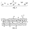
- Figure 7 shows cube-corner elements intersected by a plane that is parallel to the front surface 51. As illustrated, the plane does not intersect each cube to produce a triangle 62 of the same cross-sectional area.
- One cube may be tilted or offset from the front surface 51 to such an extent that the intersecting plane only passes through a tip of the cube, resulting in a small triangular cross-section -- whereas, a cube that stands upright may be intersected such that the triangle resulting from the cross-section is relatively large.
- the cube-corner elements in the array may be of similar size, they can produce triangles of random sizes when intersected as described because of the manner in which the cubes are tilted or offset with respect to a reference plane.
- the spacing between the cube-comer elements 30 can vary, as will be discussed below, although retroreflectivity tends to decrease as spacing increases.
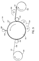
- the cube-comer elements 30 may optionally be coated with a reflective material on the surface 67, such as vapor depositing or chemically depositing a metal such as aluminum, silver, nickel, tin, copper, or dielectric materials as are known in the art of cube-corner retroreflective articles. It will be understood that the retroreflective sheeting 61 will typically have a metal layer on the surface 67 or a seal film 63, but not both.
- the sealing layer comprises a thermoplastic material with a similar low elastic modulus as the overlay film 68.
- Illustrative examples include ionomeric ethylene copolymers, plasticized vinyl halide polymers, acid functional polyethylene copolymers, aliphatic polyurethanes, aromatic polyurethanes, and combinations thereof.
- the optional sealing layer 63 can provide significant protection for the cube-corner elements of the composite material from environmental effects, as well as maintaining a sealed air layer around the cube-corner elements which is essential for creating the refractive index differential needed for total internal reflection.
- the sealing layer 63 may optionally be adhered, at least in part, directly to the overlay film 68 between independent cube-corner elements.
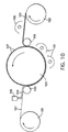
- FIG. 9 is a schematic illustration of an apparatus 120 for casting and curing retroreflective sheeting suitable for use in the present invention.
- Overlay film 121 is drawn along guiding roller 122 or from a stock roll of material to nip roller 123, e.g., a rubber coated roller, where overlay film 121 contacts suitable resin formulations 124 previously applied to patterned tool roll 125 through coating die 126.
- nip roller 123 e.g., a rubber coated roller
- the excess resin extending above the cube-corner element forming cavities 127 of tool 125 is minimized by setting nip roller 123 to a gap setting that is effectively less than the height of the cube-corner forming elements of tool 125. It will be understood that the gap setting may be achieved by applying pressure to the nip roller 123.
- film 121 may be optionally supported with suitable carrier film 128 that provides structural and mechanical durability to overlay film 121 during casting and curing.
- the carrier film 128 may be stripped from overlay film 121 after the sheeting is removed from tool 125 or left intact for further processing of the retroreflective sheeting. Use of such a carrier film is particularly preferred for low modulus overlay films.
- the resin composition that forms the retroreflective array of cube-corner elements can be cured in one or more steps.
- Radiation sources 129 expose the resin to actinic radiation, e.g., ultraviolet light, visible light, etc. depending upon the nature of the resin in a primary curing step through the overlay film.
- actinic radiation e.g., ultraviolet light, visible light, etc.
- the selected overlay film need not be completely or 100 percent transparent to all possible wavelengths of actinic radiation that may be used in curing the resin.
- curing can be performed by irradiation through a transparent tool 125, such as disclosed in U.S. Patent No. 5,435,816.
- the tool 125 has a molding surface having a plurality of cavities opening thereon which have the shape and size suitable for forming desired cube-comer elements.
- the cavities, and thus resultant cube-corner elements may be three sided pyramids having one cube-corner each, e.g., such as are disclosed in the U.S. Patent No. 4,588,258, may have a rectangular base with two rectangular sides and two triangular sides such that each element has two cube-corners each, e.g., such as are disclosed in U.S. Patent No. 4,938,563 (Nelson et al.), or may be of other desired shape, having at least one cube-corner each, e.g., such as are disclosed in U.S. Patent No. 4,895,428 (Nelson et al.). It will be understood by those skilled in the art that any cube-corner element may be used in accordance with the present invention.
- the tool 125 should be such that the cavities will not deform undesirably during fabrication of the composite article, and such that the array of cube-corner elements can be separated therefrom after curing.
- Materials useful in forming tooling 125 preferably machine cleanly without burr formation, exhibit low ductility and low graininess, and maintain dimensional accuracy after groove formation.
- the tool can be made from polymeric, metallic, composite, or ceramic materials.
- curing of the resin will be performed by applying radiation through the tool.
- the tool should be sufficiently transparent to permit irradiation of the resin therethrough.
- Illustrative examples of materials from which tools for such embodiments can be made to include polyolefins and polycarbonates.
- Metal tools are typically preferred, however, as they can be formed in desired shapes and provide excellent optical surfaces to maximize retroreflective performance of a given cube-corner element configuration.
- the primary curing can completely or partially cure the cube-corner elements.
- a second radiation source 130 can be provided to cure the resin after sheeting 131 has been removed from tool 125.
- the extent of the second curing step is dependent on a number of variables, among them the rate of feed-through of the materials, composition of the resin, nature of the crosslinking initiators used in the resin formulation, and the geometry of the tool.
- Illustrative examples include electron beam exposure and actinic radiation, e.g., ultraviolet radiation, visible light radiation, and infrared radiation.
- Removal of the retroreflective sheeting 131 from the tooling 125 typically generates sufficient mechanical stresses to fracture the minimal land area between the cube-corner elements, if any, that exists between the individual cube-corner elements of the sheeting.
- the decoupled, independent nature of the discrete cube-corner elements and strong bond of each independent element to the overlay film gives the retroreflective sheeting substantial flexibility, while retaining high levels of retroreflective performance after undergoing mechanical deformation stresses.
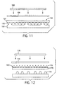
- FIG 10 illustrates an alternate apparatus for casting and curing retroreflective sheeting suitable for making the present retroreflective article.
- Resin composition 124 is cast directly onto overlay film 121.
- the resin-film combination is then contacted with patterned tool roll 125 with pressure being applied through appropriate setting of nip roller 123.
- nip roller 123 serves to minimize the amount of resin extending above the cube-corner forming cavities 127 of tool 125.
- the resin can be cured by exposure to actinic radiation from a first radiation source 129, and optional second radiation source 130.
- the actinic radiation from first radiation source 129 must first pass through overlay film of the sheeting before impinging on the resin.
- the individual or discrete cube-comer elements are essentially totally decoupled from each other, providing the ultra-flexible character of the composite retroreflective sheeting.
- the decoupled cube-corner elements are no longer mechanically constrained by the effect of any land area, minimizing the mechanical stresses that might tend to deform them and lead to degradation of retroreflective performance.
- the discrete cube-corner elements of retroreflective sheeting retain a high degree of retroreflective brightness after being deformed.
- Retroreflective sheeting prepared according to the above method exhibits a retroreflective brightness, i.e., a coefficient of retroreflection, of greater than about 50, preferably greater than about 250, and more preferably greater than about 500, candela/lux/square meter, measured at an entrance angle of -4° and an observation angle of -0.2°, when the sheeting is in a planar, non-deformed configuration.
- a retroreflective brightness i.e., a coefficient of retroreflection
- a coefficient of retroreflection of greater than about 50, preferably greater than about 250, and more preferably greater than about 500, candela/lux/square meter, measured at an entrance angle of -4° and an observation angle of -0.2°, when the sheeting is in a planar, non-deformed configuration.
- planar it is meant that the sheeting is permitted to lay flat and by non-deformed it is meant that the sheeting has not been mechanically stressed after decoupling of the cube-corner elements.
- the resin composition and overlay film are preferably such that when the resin composition contacts the overlay film it penetrates the overlay film so that after the primary curing treatment an interpenetrating network between the material of the cube-comer elements and the material of the overlay film is formed.
- the array of cube-corner elements preferably comprises a material that is thermoset or extensively crosslinked, and the overlay film preferably comprises a thermoplastic material. The superior chemical and mechanical properties of thermoset materials yield cube-corner elements optimally capable of maintaining desired retroreflectivity.
- elastic modulus means the elastic modulus determined according to ASTM D882-75b using Static Weighing Method A with a 12.5 centimeter (5 inch) initial grip separation, a 2.5 centimeter (1 inch) sample width, and a 2.5 centimeter/minute (1 inch/minute) rate of grip separation.
- elastic modulus may be determined according to standardized test ASTM D882-75b using Static Weighing Method A with a five inch initial grip separation, a one inch sample width, and an inch per minute rate of grip separation. Under some circumstances, the polymer may be so hard and brittle that it is difficult to use this test to ascertain the modulus value precisely (although it would be readily known that it is greater than a certain value). If the ASTM method is not very suitable, another test, known as the "Nanoindentation Technique" may be employed. This test may be carried out using a microindentation device such as a UMIS 2000 available from CSIRO Division of Applied Physics Institute of Industrial Technologies of Lindfield, New South Wales, Australia.
- the overlay film of the composite retroreflective sheeting is preferably a polymeric material of somewhat lower elastic modulus.
- the overlay film can deform along with the shrinkage of cube-corner elements without exerting such deformational stresses on the cube-corner elements that would lead to undesirable degradation of the optical characteristics.
- the modulus differential between the overlay film and the cube-corner elements should be on the order of 1.0 to 1.5 x 10 7 pascals or more.
- the cube-corner elements As the height of the cube-corner elements diminishes, it is possible for this modulus differential to reach the low end of the range given immediately above. However, it should be kept in mind that there is a practical lower limit to the modulus of the cube-corner element material. Below a certain level, generally on the order of about 2.0 to 2.5 x 10 8 pascals for cube-comer elements about 175 microns (0.007 inches) in height, less for smaller cube-corner elements, the cube-corner elements become too flexible and do not possess sufficient mechanical rigidity to properly fracture upon application of stress.
- the cube-corner elements preferably have an elastic modulus of greater than about 25 x 10 8 pascals.
- the thickness of the land area i.e., the thickness of the cube-corner array material opposite the plane defined by the bases of the cube-corner elements, is preferably less than 10 percent of the height of the cube-corner elements, and more preferably less than 1 percent thereof.
- the resin will shrink at least 5 percent by volume when cured, more preferably between 5 and 20 percent by volume, when cured. It has been found that by using resin compositions of this type, cube-corner arrays with minimal or no land area thickness can be more easily formed, thereby achieving the high flexibility. For instance, resin compositions that shrink when cured will tend to retreat into the cube-comer-shaped cavity, tending to leave a land area that only connects adjacent cavities and therefore adjacent cube-corners with a narrow portion if applied to the tool in appropriate quantities. The narrow portion is readily broken resulting in decoupling of individual cube-comer elements as discussed below.
- Sheeting can in theory be formed with essentially no land area connecting adjacent cube-corner elements, however, in typical high volume manufacturing arrangements, a minimal land area having a thickness of up to 10 percent of the height of the cubes, preferably on the order of 1 to 5 percent, will be formed.
- Resins selected for use in the array of cube-corner elements include cross-linked acrylate such as mono- or multi-functional acrylates or acrylated epoxies, acrylated polyesters, and acrylated urethanes blended with mono- and multi-functional monomers are typically preferred. These polymers are typically preferred for one or more of the following reasons: high thermal stability, environmental stability, and clarity, excellent release from the tooling or mold, and high receptivity for receiving a reflective coating.
- Examples of materials suitable for forming the array of cube-corner elements are reactive resin systems capable of being cross-linked by a free radical polymerization mechanism by exposure to actinic radiation, for example, electron beam, ultraviolet light, or visible light. Additionally, these materials may be polymerized by thermal means with the addition of a thermal initiator such as benzoyl peroxide. Radiation-initiated cationically polymerizable resins also may be used.
- Reactive resins suitable for forming the array of cube-corner elements may be blends of photoinitiator and at least one compound bearing an acrylate group. Preferably the resin blend contains a monofunctional, a difunctional, or a polyfunctional compound to ensure formation of a cross-linked polymeric network upon irradiation.
- Illustrative examples of resins that are capable of being polymerized by a free radical mechanism that can be used herein include acrylic-based resins derived from epoxies, polyesters, polyethers, and urethanes, ethylenically unsaturated compounds, aminoplast derivatives having at least one pendant acrylate group, isocyanate derivatives having at least one pendant acrylate group, epoxy resins other than acrylated epoxies, and mixtures and combinations thereof.
- the term acrylate is used here to encompass both acrylates and methacrylates.
- U.S. Patent 4,576,850 (Martens) discloses examples of crosslinked resins that may be used in cube-corner element arrays.
- Ethylenically unsaturated resins include both monomeric and polymeric compounds that contain atoms of carbon, hydrogen and oxygen, and optionally nitrogen, sulfur, and the halogens may be used herein. Oxygen or nitrogen atoms, or both, are generally present in ether, ester, urethane, amide, and urea groups. Ethylenically unsaturated compounds preferably have a molecular weight of less than about 4,000 and preferably are esters made from the reaction of compounds containing aliphatic monohydroxy groups, aliphatic polyhydroxy groups, and unsaturated carboxylic acids, such as acrylic acid, methacrylic acid, itaconic acid, crotonic acid, iso-crotonic acid, maleic acid, and the like. Such materials are typically readily available commercially and can be readily cross linked.
- Cationically polymerizable materials that may be used herein include but are not limited to materials containing epoxy and vinyl ether functional groups. These systems are photoinitiated by onium salt initiators, such as triarylsulfonium, and diaryliodonium salts.
- the overlay film used is a polymeric material selected from the group consisting of ionomeric ethylene copolymers, plasticized vinyl halide polymers, acid functional polyethylene copolymers, aliphatic polyurethanes, aromatic polyurethanes, other light transmissive elastomer, and combinations thereof.
- Such materials typically provide overlay films that are imparted with the desired durability and flexibility to the resultant retroreflective sheeting while permitting desired preferred penetration by the cube-corner element resin composition.
- the overlay film preferably comprises a low elastic modulus polymer, e.g., less than about 13 x 10 8 pascals, to impart easy bending, curling, flexing, conforming, or stretching to the resultant retroreflective composite.
- the overlay film comprises a polymer having a glass transition temperature less than about 50°C.
- the polymer preferably is such that the overlay film retains its physical integrity under the conditions it is exposed to as the resultant composite retroreflective sheeting is formed.
- the polymer desirably has a Vicat softening temperature that is greater than 50 °C.
- the linear mold shrinkage of the polymer desirably is less than 1 percent, although certain combinations of polymeric materials for the cube-corner elements and the overlay will tolerate a greater extent of shrinkage of the overlay material.
- Preferred polymeric materials used in the overlay are resistant to degradation by UV light radiation so that the retroreflective sheeting can be used for long-term outdoor applications.
- the overlay film should be light transmissive and preferably is substantially transparent.
- the overlay film may be either a single layer or multi-layer component as desired. Either surface of the overlay film may contain printed or formed (such as stamped or embossed) symbols. If multilayer, the layer to which the array of cube-corner elements is bonded should have the properties described herein as useful in that regard with other layers not in contact with the array of cube-comer elements having selected characteristics as necessary to impart desired characteristics to the resultant composite retroreflective sheeting.
- An alternate overlay is disclosed in U.S. Patent Application Serial No. 08/516,165 filed August 17, 1995.
- the overlay film should be sufficiently extensible to achieve decoupling of the cube-corner elements as discussed herein. It may be elastomeric, i.e., tend to recover to at least some degree after being elongated, or may have substantially no tendency to recover after being elongated, as desired.
- Illustrative examples of polymers that may be employed in overlay films herein include:
- UV absorbers ultraviolet absorbers
- light stabilizers free radical scavengers or antioxidants
- processing aids such as antiblocking agents, releasing agents, lubricants, and other additives
- processing aids such as antiblocking agents, releasing agents, lubricants, and other additives
- the particular colorant selected depends on the desired color; colorants typically are added at about 0.01 to 1.5 weight percent for a given layer.
- UV absorbers typically are added at about 0.5 to 2.0 weight percent.
- UV absorbers include derivatives of benzotriazole such as TINUVIN Brand 327, 328, 900, 1130, TINUVIN-P Brand, available from Ciba-Geigy Corporation, Ardsley, New York; chemical derivatives of benzophenone such as UVINUL Brand M40, 408, D-50, available from BASF Corporation, Clifton, New Jersey; SYNTASE Brand 230, 800, 1200 available from Neville-Synthese Organics, Inc., Pittsburgh, Pennsylvania; or chemical derivatives of diphenylacrylate such as UVINUL Brand N35, 539, also available from BASF Corporation of Clifton, New Jersey.
- benzotriazole such as TINUVIN Brand 327, 328, 900, 1130, TINUVIN-P Brand, available from Ciba-Geigy Corporation, Ardsley, New York
- benzophenone such as UVINUL Brand M40, 408, D-50, available from BASF Corporation, Clifton, New Jersey
- Light stabilizers that may be used include hindered amines, which are typically used at about 0.5 to 2.0 weight percent.
- hindered amine light stabilizers include TINUVIN Brand 144, 292, 622, 770, and CHIMASSORB Brand 944 all available from the Ciba-Geigy Corp., Ardsley, New York. Alternate hindered amines are disclosed in U.S. Patent No. 5,387,458.
- Free radical scavengers or antioxidants may be used, typically, at about 0.01 to 0.5 weight percent, Suitable antioxidants include hindered phenolic resins such as IRGANOX Brand 1010, 1076, 1035, or MD-1024, or IRGAFOS Brand 168, available from the Ciba-Geigy Corp., Ardsley, New York. Small amounts of other processing aids, typically no more than one weight percent of the polymer resins, may be added to improve the resin's processability.
- Useful processing aids include fatty acid esters, or fatty acid amides available from Glyco Inc., Norwalk, Connecticut, metallic stearates available from Henkel Corp., Hoboken, New Jersey, or WAX E Brand available from Hoechst Celanese Corporation, Somerville, New Jersey.
- the present retroreflective article can be made in accordance with two different techniques.
- a retroreflective article is made by providing a first cube-corner sheeting that has the cubes arranged in a conventional configuration, namely, a non-random orientation, and deforming this sheeting under heat and/or pressure.
- the deformed retroreflective article can be used to create tooling.
- the tooling may be used as a mold to cast or form additional retroreflective articles
- the retroreflective article of the present invention is made by thermoforming the cube-corner retroreflective sheeting over a structured three-dimensional surface of a mold, such as illustrated in Figures 11 and 12.
- the cube-comer elements 150 are placed over the structured surface of a mold 152.
- the overlay film 154 is located opposite an isolation web 156 to prevent the overlay film 154 from melting or adhering to diaphragm 158.
- the diaphragm 158 may have release properties that perform the function of the isolation web 156.
- Heat and/or pressure are applied to the retroreflective sheeting 160 through the thermoforming diaphragm 158.
- the three-dimensional shape of the mold 152 may also include a variety of embossed symbols.
- overlay film 170 is placed on the structured surface of a mold 172.
- the cube-corner elements 174 are located opposite an isolation web 176.
- Heat and/or pressure are applied to the retroreflective sheeting 180 through the diaphragm 178.
- An apparatus suitable for thermoforming the retroreflective sheeting to form the present retroreflective article is available under the trade designation ScotchliteTM Heat Lamp Vacuum Applicator available from Dayco Industries, Inc. of Niles, MI or P.M Black Co. of Stillwater, MN.
- thermoforming processing variables that may determine the nature of the retroreflective article created include temperature, pressure, duration of each, thickness and thermal characteristics of the thermoforming diaphragm and the nature of the structured surface on the mold.
- the size, uniformity and rigidity of the mold may also alter the processing specifications of the thermoforming process as well as whether the mold has an optical or a non-optical pattern.
- the construction of the retroreflective sheeting, such as the thickness, softening temperature and extensibility of the overlay film, size of the cube-corner elements, the presence or absence of a vapor coat, whether a sealing film is present and the optical design of the retroreflective sheeting may also determine thermoforming processing variables.
- Vacuum forming yields a retroreflective article in which the overlay film becomes thinner in proportion to the distance the sheet travels to contact the mold surface. Consequently, the spacing gradient between adjacent cube-comer elements increases from the top of a protrusion on the mold toward the bottom of the depression. The increased spacing generally produces lower retroreflectivity. Additionally, if the retroreflective sheeting includes a sealing film, the film is visible through the gap between the cube-corner elements.
- the sealing film may be applied either before or after deformation of the cube-corner sheeting.
- the sealing film may include one or more colors that would be visible during daytime viewing.
- a colored back coating may be visible through separations between the cube-corner elements.
- a colored back coating or adhesive serves to soften or alter the color and reduce the "grayness" of the specular reflector layer.
- the specular reflector may be a "non-silver" color, such as copper.
- the retroreflective sheeting may be deformed by drape forming.
- the thickness distribution of the overlay film using drape forming is opposite that of vacuum forming, so that the spacing gradient between the cube-corner elements increases along the top of a protrusion during formation, while the spacing between cube-corner elements along the bottom of a depression remains generally the same.
- the retroreflective sheeting may also be stretched in one or more directions prior to or during deformation. Stretching increases the gap between adjacent cube-corner elements and thereby reduces retroreflectivity. Reduced retroreflectivity may be desirable for some applications.
- the retroreflective article of the present invention may be used to prepare a master tooling which can in turn be used to prepare additional retroreflective articles.
- Retroreflective sheeting may be prepared directly from the tooling.
- Use of such masters produces sheeting that is capable of retroreflecting light and displays the target optical properties of the original retroreflective article from which the tooling was prepared. Images printed, deposited, or formed directly on the exposed back side of the cube-corner elements by various techniques may also be replicated in the mold making process.
- Angularity refers to the concept of how retroreflectivity varies as the entrance angle varies. Retroreflectivity varies according to the entrance angle and the observation angle.
- the entrance angle is the angle between an illumination axis from a light source and a retroreflector axis normal to the surface of the retroreflective article. Entrance angle is usually no larger than 90°.
- Angularity is typically described in terms of a plot of retroreflectivity on the vertical axis versus entrance angle on the horizontal axis. When the illumination axis, observation axis and retroreflector axis are in the same plane, the entrance angle can be considered negative when the retroreflector axis and observational axis are on opposite sides of the illuminator axis.
- the observation angle is the angle between the illumination axis from the light source and the observation axis.
- the observation angle is always positive and is typically a small acute angle.
- Optical profile refers to the concept of rotational and orientational symmetry of a retroreflective article.
- Rotational and orientational symmetry refers to how the retroreflected light varies as the retroreflective article is rotated about a normal perpendicular to the retroreflective surface.
- Plots of symmetry of rotation indicate how the retroreflective performance of an article will vary when oriented in varying directions about this axis.
- Figure 3 is an example of a plot of an optical profile.
- the retroreflective sheeting included cube-comer elements with optical axes tilted or canted with respect to one another, such as generally shown in U.S. Patent No. 4,588,258 to Hoopman.
- R A The coefficient of retroreflection, R A , was measured in accordance with standardized test ASTME 810-93b. R A values are expressed in candelas per lux per square meter (cd ⁇ lx -1 ⁇ m -2 ).
- Darocur Brand 4265 50:50 blend of 2-hydroxy-2-methyl-1-phenylpropan-1-one and 2,4,6-trimethylbenzoyldiphenylphosphine oxide, available from Ciba-Geigy Corp., Hawthorne, NY
- Darocur Brand 4265 50:50 blend of 2-hydroxy-2-methyl-1-phenylpropan-1-one and 2,4,6-trimethylbenzoyldiphenylphosphine oxide, available from Ciba-Geigy Corp., Hawthorne, NY
- Photomer Brand 4035 phenoxyethyl acrylate available from Henkel Corp. of Ambler, PA
- Photomer Brand 3016 bis-phenol A epoxy diacrylate available from Henkel Corp.
- the resin composition was cast onto a 0.152 mm (0.006 inches) thick aliphatic polyurethane overlay film (MORTHANE Brand 3429 urethane from Morton International, Inc., Seabrook, NH) on a polyethylene terephthalate (PET) carrier film.
- the coated film was passed between a polyurethane nip roll and a nickel electroformed tool to create 62.5 microns (0.0025 inches) tall cube-comer elements at 57°C (135°F).
- the gap between the 90 durometer polyurethane rubber nip roll and the nickel tool was set to minimize the resin in the cavities.
- the resin was cured through both the overlay film and the carrier film with one AETEK medium pressure mercury lamp (available from AETEK International of Plainfield, IL) set at 160 watts/cm (400 W/in).
- the feed rate of material through the cure station was 1.524 meters/min. (5 fpm).
- the side of the composite with the cube-comer elements was post-cured by irradiating it with a medium pressure mercury lamp (AETEK International) operating at 80 watts/cm (200 w/in).
- AETEK International medium pressure mercury lamp
- Example 1 The retroreflective sheeting of Example 1 was placed into a clamping frame with the piano-side (overlay film) of the film facing upward on a vacuum-former Type Comet, Jr., Model 10X10 from Comet Industries, Inc. of Sanford, FL. After heating the film to approximately 150 °C using the resistance heater on the vacuum former, the film started to sag (approximately 20 seconds). The softened composite film was rapidly lowered onto a porous mold bearing a rectangular array of 90 (9 ⁇ 10) hemi-spherical ⁇ 1.59cm (0.625 inch) diameter depressions while a vacuum was being applied to the mold.
- the softened film formed a reflective sheet with retroreflective hemi-spherical cavities or depressions, shown in both a plan view and a perspective view in Figures 13.
- Figure 16 illustrates an alternate retroreflective article with hemi-spherical protrusions formed using the process of the present Example.
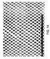
- Figure 14 is a photomicrograph (50X) taken from the cube side of the deformed retroreflective sheeting at the bottom of a vacuum-formed depression of Figure 13.
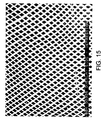
- Figure 15 is a photomicrograph (50X) taken of a vacuum-formed depression from the overlay side.
- the cube-comer elements are shown in dark and the separations between them in white.
- the photomicrograph illustrates that a ratio of the base edge of the cube-corner elements to the separations therebetween is in the range of about 0.5:1 to 2:1.
- the cube-corner elements are nominally adjacent to one another prior to deformation.
- the vacuum forming process stretches and thins the overlay film and increases the separation of the cube-corner elements at the bottom of a depression.
- the generally uniform separation between the cube-corner elements is enhanced by heating the retroreflective sheeting to soften the overlay film prior to vacuum forming.
- Example 1 The retroreflective sheeting of Example 1 was placed into a clamping frame with the piano-side of the film facing downward.
- the film was heated using the method of Example 2 until the film started to sag (approximately 10-15 seconds).
- the softened composite film was rapidly lowered onto a porous mold bearing a rectangular array of 90 (9 ⁇ 10) hemi-spherical depressions ( ⁇ 0.75 inch diameter), such as illustrated in Figure 13, while a vacuum was being applied to the mold.
- the softened film formed a reflective sheet with retroreflective hemi-spherical protrusions.
- Figure 17 is a photomicrograph (50X) taken from the cube side of the deformed retroreflective sheeting at the top of a vacuum-formed protrusion.
- Figure 18 is a photomicrograph (50X) taken of a vacuum-formed protrusion from the overlay side.
- the cube-comer elements are shown in dark and the separations between them in white.
- the cube-corner elements are nominally adjacent to one another.
- the vacuum forming process stretches and thins the overlay film and increases the separation of the cube-corner elements at the top of a protrusion.
- the separations between the cube-comer elements are random due to non-uniform heating and draw, primarily a function of the shortened heating cycle.
- cube-corner elements are grouped together, others are isolated.
- the random separation of the cube-corner elements created a glittery visual appearance. It will be understood that the separation between the cube-corner elements can be further altered by controlling the draw ratio of the overlay film over the mold.
- the present photomicrographs of the retroreflective sheeting with enhanced glittering showed a substantially greater degree of cube-corner element reorientation and separation, than is present on undeformed retroreflective sheeting. It is believed that the enhanced glittering effect is related to the additional reflective paths available to light incident on the adjacent cube-comer elements. Accordingly, there is a general range of glittering image forming abilities of the retroreflective article of the invention which can be achieved by changing the processing variables.
- the retroreflective sheeting of Example 1 was metallized by vapor deposition of aluminum metal on the cube-corner elements.
- the metallized retroreflective sheeting was vacuum-formed with the piano-side of the film in contact with a mold to form a series of letters that spelled the word "VIPER" as shown in Figure 19. While the formed film was still in the mold, a two-part polyurethane was poured into the cavity to backfill the cube-corner elements and thermally cured. The individual letters were cut out and adhered to a steel plate with a gloss black coating.
- the retroreflective sheeting is generally planar, except along the transition edges of the letters.
- the retroreflective article exhibited standard retroreflectivity along the planar surface. Some localized glitter-effect was noted along the transition edges of the letters.
- a mixture of 1 percent by weight of Darocur Brand 4265 (50:50 blend of 2-hydroxy-2-methyl-1-phenylpropan-1-one and 2,4,6-trimethylbenzoyldiphenylphosphine oxide, available from Ciba-Geigy Corp., Hawthorne, NY) was added to a resin mixture of 19 percent by weight PHOTOMER Brand 3016 (a bisphenol A epoxy diacrylate, available from Henkel Corp., Ambler, PA), 49.5 percent by weight TMPTA (trimethylolpropane triacrylate) and 30.5 percent by weight Sartomer 285 (THFA is tetrahydrofurfuryl acrylate, available from Sartomer Corp.).
- PHOTOMER Brand 3016 a bisphenol A epoxy diacrylate, available from Henkel Corp., Ambler, PA
- TMPTA trimethylolpropane triacrylate
- Sartomer 285 THFA is tetrahydrofurfuryl acrylate, available from Sarto
- This resin composition was cast at 57°C (135°F) between a tool with 85 microns (0.0034 inches) tall cube-corner elements and an aliphatic polyurethane overlay film 0.114 mm (0.0045 inches) thick (MORTHANE Brand 3429 urethane from Morton International, Inc., Seabrook, NH) on a polyethylene terephthalate (PET) carrier film 0.51 mm (0.002 inches) thick.
- PET polyethylene terephthalate
- the rubber nip roll gap was set to minimize the amount of resin composition over the cavities of the tool.
- the resin was cured through both the overlay film and carrier film with one AETEK medium pressure mercury lamp (available from AETEK International of Plainfield, Illinois) set at 160 watts/cm (400 watts/in).
- the feed rate of material through the cure station was controlled to attain the desired degree of curing (exposure to 100 to 1000 millijoules/cm 2 ).
- the cube-corner side of the composite post-cured by irradiating it with a medium-pressure mercury lamp (AETEK International) operated at 80 watts/cm (200 W/in).
- AETEK International medium-pressure mercury lamp
- the retroreflective sheeting of Example 5 was thermally sealed to a white polyurethane sealing film as follows.
- a laminate sample of retroreflective sheeting and sealing film was prepared by first protecting it with a 0.025 mm (0.001 inch) polyester terephthalate film. This construction was then fed into a nip between a heated steel embossing roll and a 85 durometer rubber roll.
- the sealing film was a 0.05 mm (0.002 inches) thick white (TiO 2 ) pigmented aliphatic polyester urethane (MORTHANE Brand PNO3 supplied by Morton International, Seabrook, New Hampshire).
- the embossing pattern was of a chain link configuration and the embossing roll surface was 220°C (410°F).
- the rubber roll surface temperature was 63°C (145°F).
- the rolls were turning at a surface speed of 6.09 meters/minute (20 feet/minute), and the force on the nip was held at 114 Newtons/centimeter (65 pounds/inch).
- the polyester terephthalate protective layers were removed from the samples prior to further use,
- a 152.4 x 304.8 mm (6" ⁇ 12") piece of the retroreflective sheeting with a sealing film was prepared as described in Example 6.
- the sealed cube sheeting was then laminated to a pressure sensitive adhesive with a liner, product number 467 MP available from Minnesota Mining and Manufacturing Company of St. Paul, MN.
- the liner was removed and the sheeting was laminated to a flat, white license plate blank.
- the resulting article was embossed using conventional license plate embossing techniques.
- the sample embossed very well and did not tent over the letters. In the view box, the sample was noticeably brighter and whiter than conventional beaded license plate sheeting.
- the candela/lux/square meter was 200 in the horizontal direction and 300 in the vertical direction.
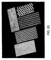
- Example 8 Flexible retroreflective sheeting embossed over netting
- the retroreflective sheeting of Example 6 using a pressure sensitive adhesive was embossed over five samples of small mesh industrial netting, as shown in Figure 20. Heat lamination of the retroreflective sheeting is preferable, because it helps the retroreflective sheeting conform to the underlying netting.
- the netting changed both the angularity of the cube-comer elements and acted as a filler or cushion for the embossed retroreflective sheeting.
- the portion of the retroreflective sheeting deformed by the netting is shown in white and the space between the netting is shown in black.
- a localized glitter-effect was visible along the sharp transition regions in the retroreflective sheeting deformed over the netting.
- a metallized retroreflective sheeting with a suitable adhesive may alternately be embossed over the netting.
- One possible use could be in temporary pavement markings, which need a different angularity from standard retroreflective sheeting, as well as cushioning when run over by a car.
- Example 1 The retroreflective sheeting of Example 1 was vacuum formed on a mold bearing a ® symbol approximately 6.35 mm in diameter.
- Figure 21 is a photomicrograph (50X) taken from the overlay side of the retroreflective sheeting. The cube-corner elements are shown in black and the separations in white. The asymmetry of the ® symbol prevented a uniform draw, resulting in substantial randomization of the cube-corner elements.
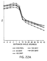
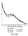
- An unsealed retroreflective sheeting according to Example 5 with cube-corner elements 0.086 mm (0.0034 inches) high was thermo-formed over 60, 100, 150 and 220 grit coated abrasive paper available from Minnesota Mining and Manufacturing Company of St. Paul, MN using the ScotchliteTM Heat Lamp Vacuum Applicator discussed above.
- the cube-corner elements were positioned opposite the coated abrasive paper.
- the bake cycle included warming the applicator to approximately 118 °C and baking for about 1.5-2.5 minutes.
- the lamp bank was raised at the end of the bake cycle to cool the retroreflective articles.
- Figure 22A is a plot of the relative brightness versus entrance angle for the resulting retroreflective articles.
- Figure 22B is a plot of the relative brightness versus the observation angle.
- the control plot is the undeformed retroreflective sheeting.
- the retroreflective article had a glittery appearance presumably due to the high level of randomization of the base edges of the cube-corner elements.
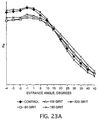
- FIG. 23A is a plot of the relative brightness versus entrance angle for the resulting retroreflective articles.
- Figure 23B is a plot of the relative brightness versus the observation angle. The control plot is the undeformed metallized retroreflective sheeting.
- the retroreflective article had a glittery appearance presumably due to the high level of randomization of the base edges of the cube-comer elements.
- the retroreflective sheeting was also thermo-formed over a beaded pavement marker available under product designation 5160 ScotchlaneTM foil backed tape from Minnesota Mining and Manufacturing Company of St. Paul, MN according to the method of Example 10.
- Figure 23C is a bar graph showing the increase in whiteness of the retroreflective sheeting after the thermo-forming process for the four coated abrasive paper specimens and the beaded pavement marker. Whiteness is measured using a spectrophotometer with a bidirectional optical measuring system according to ASTM E 1349-90. Whiteness is believed to be an approximate measure of the glittery appearance of retroreflective sheeting.
- the level of whiteness for the retroreflective article thermo-formed over the 100 grit coated abrasive paper is believed to be a function of the size of the cube-corner elements relative to the grit of the coated abrasive paper. That is, the 100 grit coated abrasive paper provided the greatest level of randomization of the base edges of cube-comer elements 0.086 mm high.
- Example 5 An unsealed retroreflective sheeting according to Example 5 with cube-comer elements 0.086 mm (0.0034 inches) high was thermo-formed over a series of specimens using the method of Example 10.
- the specimen included a beaded pavement marker available under product designation 5160 ScotchlaneTM foil backed tape and a raised pavement marker available under product designation A381 StamarkTM high performance tape, both from Minnesota Mining and Manufacturing Company of St. Paul, MN; a tool for manufacturing retroreflective sheeting with cube-corner elements 0.178 mm (0.007 inches) high; and a light diffuser available under the product designation Clear Prismatic from Plaskolite, Inc. of Columbus, OH.
- the cube-corner elements were positioned opposite the specimens.
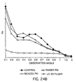
- Figure 24A is a plot of the relative brightness versus entrance angle for the resulting retroreflective articles.
- Figure 24B is a plot of the relative brightness versus the observation angle. The control plot is undeformed retroreflective sheeting. Variation in the glittery appearance of the retroreflective articles was presumably due to the various levels of randomization of the base edges of the cube-comer elements.
- An unsealed retroreflective sheeting according to Example 5 with cube-comer elements 0.086 mm (0.0034 inches) high was metallized by vapor deposition of aluminum metal on the cube-comer elements.
- the metallized retroreflective sheeting was thermo-formed over the beaded pavement marker, raised pavement marker and light diffuser of Example 12 using the method of Example 10.
- the cube-comer elements were positioned opposite the specimens.
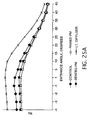
- Figure 25A is a plot of the relative brightness versus entrance angle for the resulting retroreflective articles.
- Figure 25B is a plot of the relative brightness versus the observation angle. The control plot is the undeformed retroreflective sheeting.
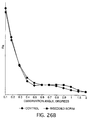
- the metallized retroreflective sheeting was thermo-formed using the method of Example 10 over a polypropylene industrial mesh netting with a 1.27 cm (0.5 inch) hex pattern, sold under the product designation NO916 by Sterling Net Co. of Montclair, NJ.
- the netting softened during the thermo-forming process and thus remained bonded to the retroreflective sheeting.
- the cube-corner elements were positioned opposite the specimens.
- Figure 26A is a plot of the relative brightness versus entrance angle for the resulting retroreflective articles.
- Figure 26B is a plot of the relative brightness versus the observation angle. The control plot is the undeformed retroreflective sheeting.
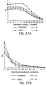
- An unsealed retroreflective sheeting according to Example 5 with cube-corner elements 0.086 mm (0.0034 inches) high was metallized by vapor deposition of aluminum metal on the cube-corner elements.
- the metallized retroreflective sheeting was thermo-formed over the cube-corner side of three commercial reflectors.
- Reflector A was a 7.62 cm (3 inch) circular reflector divided into 6 pie-shaped wedges of cube corners, sold as Model V472R from Peterson Manufacturing of Grandview, MO.
- Reflector B was a 7.62 cm (3 inch) circular reflector having about 20 diamond shaped patterns 1.27 X 2.54 cm (0.5 X 1.0 inch) containing cube corner elements, sold as Model Sate-lite-30 from KyKu Products of Bedford Heights, OH.
- the Rectangular reflector 6.35 X 7.62 cm (2.5 X 3.0 inches) had vertical rows of cube corner elements offset from each other, sold as Model PEC 4200C from The Refractory of Newburgh, NY.
- Figure 27A is a plot of the relative brightness versus entrance angle for the resulting retroreflective articles.
- Figure 27B is a plot of the relative brightness versus the observation angle. The control plot is the undeformed metallized retroreflective sheeting.
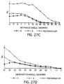
- Figures 27C is a plot of the relative brightness versus entrance angle for the commercial reflectors illustrated in Figures 27A and 27B.
- Figure 27D is a plot of the relative brightness versus the observation angle for the commercial reflectors.
Abstract
Description
- The present invention relates to a flexible, retroreflective sheeting deformed to produce target optical properties and to a process of deforming a retroreflective sheeting into a three-dimensional article with such optical properties.
- Cube-corner retroreflectors typically comprise a sheeting having a generally planar front surface and an array of cube-corner elements protruding from the back surface. Cube-corner reflecting elements comprise generally trihedral structures that have three approximately mutually perpendicular lateral faces meeting in a single corner, i.e., cube-corner. Light incident to the front surface enters the sheet, passes through the body of the sheet to be internally reflected by the faces of the elements so as to exit the front surface in a direction substantially toward the light source. The light rays are typically reflected at the cube faces due to either total internal reflection ("T.I.R."), or reflective coatings such as a vapor-deposited aluminum film. Use of metallized aluminum coating on the cube-corner elements tends to produce a gray coloration to an observer in ambient light or daylight conditions, and is thus considered aesthetically undesirable for some applications.
- A very common retroreflective sheeting uses an array of cube-corner elements to retroreflect light. Figures 1 and 2 illustrate an example of such a retroreflective sheeting, noted generally by numeral 10. The array of cube-corner elements 12 project from a first or rear side of a body portion 14 that includes a body layer 18 (also referred to in the art as an overlay) and may also include a land layer 16. Light illustrated as arrows 23 enters the cube-corner sheeting 10 through the front surface 21; it then passes through the body portion 14 and strikes the planar faces 22 of the cube-corner elements 12 to return in the direction from which it came.
- Figure 2 shows the back side of the cube-corner elements 12, where each cube-corner element 12 is in the shape of a trihedral prism that has three exposed planar faces 22. The cube-corner elements 12 in known arrays are typically defined by three sets of parallel v-shaped grooves 25, 26, and 27. Adjacent planar faces 22 on adjacent cube-corner elements 12 in each groove form an external dihedral angle (a dihedral angle is the angle formed by two intersecting planes). This external dihedral angle is constant along each groove in the array. This has been the case for the variety of previously produced cube-corner arrays.
- The planar faces 22 that define each individual cube-corner element 12 generally are substantially perpendicular to one another, as in the corner of a room. The internal dihedral angle -- that is, the angle between the faces 22 on each individual cube-corner element in the array -- typically is 90°. This internal angle, however, can deviate slightly from 90° as is well known in the art; see for example, U.S. Patent No. 4,775,219 to Appeldorn et al. Although the apex 24 of each cube-corner element 12 may be vertically aligned with the center of its base (see, for example, U.S. Patent No. 3,684,348) the apex also may be offset or canted from the base center as disclosed in U.S. Patent No. 4,588,258 to Hoopman. Other cube-corner configurations are disclosed in U.S. Patents 5,138,488. 4,066,331, 3,923,378, 3,541,606, and Re 29, 396, 3,712,706 (Stamm), 4,025,159 (McGrath), 4,202,600 (Burke et al.), 4,243,618 (Van Arnam), 4,349,598 (White), 4,576,850 (Martens), 4,588,258 (Hoopman), 4,775,219 (Appeldorn et al.), and 4,895,428 (Nelson et al.).
- Where the cube-corner retroreflective sheeting is likely to be used in an environment where it could be exposed to moisture or other elements, e.g., outdoors or in high humidity, it may be preferred that cube-corner elements are encapsulated with a conformable sealing film. The aforementioned U.S. Patent No. 4,025,159 discloses encapsulation of cube-corner elements using a sealing film.
- Basic cube-corner elements have a low angularity such that the element will only brightly retroreflect light that impinges on it within a narrow angular range centering approximately on its optical axis. The optical axis is the trisector of the internal space defined by the faces of the element. Impinging light that is inclined substantially away from the optical axis of the element strikes a face at an angle less than its critical angles, thereby passing through the face rather than being reflected.
- Figure 3 is a graph in polar coordinates of the optical profile of a basic cube-corner retroreflective sheet, having six maxima and six minima at 30° azimuthal intervals. The intensity of the retroreflective beam from a cube-corner retroreflective sheeting is greatest when the incident beam has an angle of incidence of 0° (normal to the plane of the sheeting). At higher angles of incidence (approximately greater than 30°) the brightness of the retroreflected beam is a function of the angle about an axis normal to the sheet called the azimuthal angle. When the angle of incidence of a light beam is held constant at a value of, for example 60° from normal, and the azimuthal angle of the incident beam is varied from 0° to 360°, the intensity of the retroreflected beam varies as illustrated in Figure 3.
- There are a number of applications for cube-comer retroreflective sheeting with non-standard or customized optical profiles. For example, more uniform retroreflectivity or wider retroreflective angularity than shown in Figure 3 is often required. For some applications it may be desirable to limit retroreflectivity to a narrow band of angularity and/or along a specific segment of the azimuthal angle.
- One method of changing the optical profile of cube-corner elements is to cut the master or mold formed thereon into pieces and reassembling the pieces in a pattern that produces differing zones of orientation on the retroreflective sheeting. For example, an optical profile with wide retroreflective angularity in multiple viewing planes can be achieved by rotating adjacent pieces of the mold or master 30° or 90° about an axis normal to the plane of the elements (rotating the pieces 60° or any multiple thereof effects no net change in orientation of the cube-comer elements). Reassembling the pieces of the mold or master with the necessary precision, however, is time consuming and expensive. A method of reassembling a master mold is disclosed in U.S. Patent Application Serial No. 08/587,719 filed January 19, 1996.
- Another method of changing the optical profile of cube-corner elements is to tilt or cant the optical axes of cube-comer elements with respect to one another. FIG. 4 illustrates a cube-corner element 30 with three mutually perpendicular faces 31a, 31b, and 31c that meet at the cube's apex 34. The cube's base edges 35 are generally linear and generally lie in a single plane that defines the base plane 36 of the element 30. Cube-corner element 30 also has a central or optical axis 37, which is the tri-sector of the internal angles defined by lateral faces 31a, 31b, and 31c. The optical axis may be disposed perpendicular to base plane 36, or it may be canted as described in U.S. Patent No. 4,588,258 to Hoopman and U.S. Patent No. 5,138,488 to Szczech. The cost of creating tooling necessary to practice the invention of Hoopman is relatively high. Moreover, this technique does not lend itself to rapid prototyping of customized optical profiles or angularity.
- Therefore, what is needed is a method of creating retroreflective articles with prototype or target optical properties without the need for expensive tooling.
- The present invention relates to a flexible, retroreflective sheeting deformed to produce target optical properties. The present invention is also directed to a process of deforming a retroreflective sheeting into a three-dimensional article having such optical properties.
- The retroreflective sheeting includes a multiplicity of discrete, cube-corner elements cured in situ on a transparent, polymeric overlay film. The retroreflective sheeting is deformed into a three-dimensional structure so that base edges of a plurality of cube-corner elements are non-planar with respect to one another to produce at least one target optical property. The target optical properties may be a desired optical profile, angularity, three-dimensional appearance, whiteness, glitter-effect, or combinations thereof. The retroreflective sheeting is preferably a single, unitary sheet.
- The base edges of a plurality of adjacent cube-comer elements may be non-planar or tilted with respect to one another. The base edges of one or more cube-corner elements are preferably not parallel to a front surface of the overlay film. The cube-corner elements may have a variable density across a portion of the retroreflective article. Adjacent cube-corner elements across a portion of the retroreflective article may have a variable spacing. The overlay film may have a thickness that varies across a portion of the retroreflective article.
- The present retroreflective article may be used as a master to produce tooling for forming additional retroreflective articles.
- The three-dimensional structure may have one or more embossed symbols. The retroreflective sheeting may optionally include a specular reflector coated on the cube-corner elements. The retroreflective sheeting may optionally include a sealing film extending substantially across the cube-corner elements opposite the overlay film. Metallized cube-corner elements may optionally be backfilled with a coating, such as a polymeric material, resin or adhesive. In one embodiment, the coating may be applied uniformly or in a pattern, such as printing symbols in one or more colors.
- The polymeric overlay film preferably has a first elastic modulus and the cube-corner elements preferably have a second elastic modulus greater than the first elastic modulus. The cube-comer elements preferably are constructed from a thermoset polymer. The polymeric overlay film is preferably constructed from a thermoformable polymer. The overlay film may be selected from the group consisting of the following: ionomeric ethylene copolymers, plasticized vinyl halide polymers, acid-functional ethylene copolymers, aliphatic polyurethanes, aromatic polyurethanes, other light transmissive elastomers, and combinations thereof. The cube-corner elements may be selected from the group consisting of monofunctional, difunctional, and polyfunctional acrylates or combinations thereof.
- The present invention is also directed to a method of forming a retroreflective article having at least one target optical property. A cube-comer retroreflective sheeting is prepared having a multiplicity of discrete, cube-corner elements cured in situ on a transparent, polymeric overlay film. The flexible retroreflective sheeting is deformed into a three-dimensional configuration so that the base edges of a plurality of cube-corner elements are non-planar with respect to one another.
- The step of deforming may include tilting the base edges of the plurality of adjacent cube-corner elements with respect to one another. The step of deforming is preferably selected from the group consisting of thermo-forming, vacuum-forming, embossing, and combinations thereof. The step of deforming may include forming a three-dimensional symbol in the retroreflective sheeting, altering the density and/or spacing of at least a portion of the cube-corner elements, or stretching the retroreflective sheeting in at least one direction. The step of stretching may include uniformly (or non-uniformly) stretching or biaxially stretching the retroreflective sheeting. The step of deforming may include altering the base edges of one or more cube-comer elements so that they are not parallel to a front surface of the overlay film.
- The cube-corner elements may optionally be coated with a specular reflector. A sealing film may optionally be bonded substantially across an exposed surface of the cube-corner elements either before or after the step of deforming the retroreflective sheeting.
- In an alternate embodiment, a mold is formed from the cube-corner elements of the deformed retroreflective article. A polymeric material is applied to the mold and the polymeric material is at least partially cured. The polymeric material is then removed from the mold so that a second retroreflective article is produced.
- As used herein:
- Deforming refers to thermo-forming, vacuum-forming, embossing, molding, stamping, elastic or inelastic stretching, uniformly or non-uniformly stretching, or combinations thereof.
- Symbol refers to any alphanumeric character, logo, seal, geometric pattern or combinations thereof.
- Target Optical Properties refers to a desired optical profile, angularity, three-dimensional appearance, whiteness, glitter-effect, or combinations thereof.
- The invention is further explained with reference to the drawing, wherein:
- Figure 1 is a sectional view of a prior art cube-comer retroreflective sheeting;
- Figure 2 is a bottom view of the retroreflective sheeting of Figure 1;
- Figure 3 is a graph in polar coordinates of the optical profile of a cube-corner element having six maxima and six minima at 30° azimuthal intervals;
- Figure 4 is an isometric view of a cube-corner element that may be used in a retroreflective sheeting of the invention;
- Figure 5 is a bottom view of a retroreflective article according to the present invention;
- Figure 6 is a sectional view of a retroreflective article taken along lines 6-6 of Figure 5;
- Figure 7 is a sectional view of the retroreflective article taken along lines 7-7 of Figure 6;
- Figure 8 is a sectional view of a retroreflective article having a seal film secured to the backside of the retroreflective sheeting;
- Figure 9 is a schematic illustration of a method for preparing a retroreflective sheeting;
- Figure 10 is a schematic illustration of an alternate method for preparing a retroreflective sheeting;
- Figure 11 is a schematic illustration of a method of preparing a retroreflective article;
- Figure 12 is a schematic illustration of an alternate method of preparing a retroreflective article;
- Figure 13 is a photograph of an exemplary retroreflective article;
- Figure 14 is a photomicrograph of a depression on the retroreflective article of Figure 13;
- Figure 15 is a photomicrograph of a depression on the retroreflective article of Figure 13;
- Figure 16 is a photograph of an exemplary retroreflective article;
- Figure 17 is a photomicrograph of a protrusion on the retroreflective article of Figure 16;
- Figure 18 is a photomicrograph of a protrusion on the retroreflective article of Figure 16;
- Figure 19 is a photograph of an exemplary retroreflective article containing a symbol;
- Figure 20 is a photograph of a plurality of exemplary retroreflective article;
- Figure 21 is a photomicrograph of a retroreflective article containing a ® symbol;
- Figure 22A is a graph of entrance angle versus brightness for various specimens;
- Figure 22B is a graph of observation angle versus brightness for the specimens of Figure 22A;
- Figure 23A is a graph of entrance angle versus brightness for various specimens;
- Figure 23B is a graph of observation angle versus brightness for the specimens of Figure 23A;
- Figure 23C is a bar graph of change in whiteness of various specimens after deformation;
- Figure 24A is a graph of entrance angle versus brightness for various specimens;
- Figure 24B is a graph of observation angle versus brightness for the specimens of Figure 24A;
- Figure 25A is a graph of entrance angle versus brightness for various specimens;
- Figure 25B is a graph of observation angle versus brightness for the specimens of Figure 25A;
- Figure 26A is a graph of entrance angle versus brightness for various specimens;
- Figure 26B is a graph of observation angle versus brightness for the specimens of Figure 26A;
- Figure 27A is a graph of entrance angle versus brightness for various specimens;
- Figure 27B is a graph of observation angle versus brightness for the specimens of Figure 27A;
- Figure 27C is a graph of entrance angle versus brightness for various commercial reflectors; and
- Figure 27D is a graph of observation angle versus brightness for the commercial reflectors Figure 27C.
-
- The present invention relates to a retroreflective article formed from a flexible, retroreflective sheeting to produce target optical properties and to a process of deforming a retroreflective sheeting into a three-dimensional article. The retroreflective sheeting has an array of discrete, cube-corner elements cured in situ on a transparent, polymeric overlay film. The array is deformed into a three-dimensional structure such that the base edges of a plurality of cube-corner elements do not reside in the same plane when the sheeting is laid flat.
- The retroreflective article of the present invention has the ability to reflect substantial quantities of incident light back towards the light source while exhibiting target optical properties. The present retroreflective article is suitable for being incorporated into a variety of products, such as clothing, shoes, license plates, signs, vehicle markings, cone sleeves and barrel wraps.
- Methods of making glittering retroreflective articles are disclosed in the following related applications filed on the same day herewith: "Method of Making Glittering Retroreflective Sheeting" (now U.S. Patent No. 5,770,124); "Mold for Producing Glittering Cube-Corner Retroreflective Sheeting" attorney docket No. 52471USA5A, Serial No. 08/640,383; and "Glittering Cube-Corner Retroreflective Sheeting" attorney docket No. 52373USA3A, Serial No. 08/640,326.
- Figure 5 shows the backside of a unitary cube-corner sheeting 60 that has been deformed to produce at least one target optical property. Cube-corner elements 30 are similar to those depicted in Figure 4. Each cube-corner element 30 meets, but is not necessarily connected to, an adjacent cube-corner element at a base edge 35. The array includes three sets of parallel grooves 45, 46, and 47. The external dihedral angles (designated as α in Figure 6) between faces 31 of adjacent cube-corner elements 30 vary along the grooves 45-47 in the array. The base edges 35 of the cube-corner elements in the array do not reside in the same plane. Consequently, the apex 34 of one cube, such as cube 30a may be relatively close to another apex such as that of cube 30b, but the apex of cube 30b may then be further away from another adjacent apex such as the apex of cube 30c.
- Figure 6 is an exemplary illustration of distances the base edges 35 are offset or tilted with respect to one another, or with respect to the front surface 51. For cube-comer elements that are about 50 to 200 micrometers high, the variation in height between adjacent base edges typically is about 0 to 50 micrometers. It will be understood that the present retroreflective article may be deformed on a micro or macro level. As will be discussed in the Examples, the retroreflective sheeting may be deformed over coated abrasive paper containing abrasive grains with diameters of about 100 to 550 micrometers. Abrasive grains of this size have radii of curvatures of about 50 to 225 micrometers. The retroreflective sheeting may be deformed over smaller structures, in the range of about 10 to 50 micrometers, although the change in the optical properties may be minimal. It is believed that the change in the optical properties of the retroreflective sheeting when deformed over micro structures in the range of about 250 to 10 microns is a function of the size of the cube-comer elements and the thickness of the overlay film. For example, smaller cube-comer elements and/or a thinner overlay film may be more susceptible to deformation over micro structures within this range.
- Figure 6 is a sectional view of the cube-corner sheeting 60 of Figure 5 showing the position of one cube apex relative to another. Additionally, Figure 6 shows tilting or canting of the base edges 35 relative to one another and relative to front surface 51. The base edge 35 of one cube may be disposed closer to or further away from the front surface 51 of overlay film 58 than the base edges of other adjacent cube-corner elements due to deformation of the overlay film 58. If the unitary cube-comer sheeting 60 possesses a land layer 56, it is also not uniformly spaced from the front surface 51. The cube-corner sheeting 60 preferably does not have a land area 56, such that each cube-corner element 30 is a discrete entity. When the cube-corner elements are tilted, the base edges 35 of many of the cube-corner elements 30 do not reside in the same plane when the sheeting is laid flat as shown in Figure 6. Additionally, the edges 35 of one or more cube-corner elements 30 are not parallel to the front surface 51. Either surface of the overlay film 58 may optionally contain symbols printed on or formed therein.
- Figure 6 also shows the external dihedral angle, α, that defines the angle between faces 31 of adjacent cube-corner elements 30. Angle α may vary along all grooves in a single parallel groove set, it may vary along all grooves in two parallel groove sets, or it may vary along grooves in all three groove sets in the array In an array of randomly tilted cube-corner elements, angle α varies randomly amongst adjacent faces of adjacent cube-comer elements throughout essentially the whole array
- The overlay film 58 in body portion 54 typically has an average thickness of approximately 20 to 1200 micrometers, and preferably is about 50 to 400 micrometers. The cube-corner elements typically have an average height of about 20 to 500 micrometers, more typically of about 25 to 200 micrometers. The optional land layer 56 preferably is kept to a minimal thickness of 0 to 150 micrometers, and is preferably as close to zero as possible so that the strain generated during deformation does not propagate laterally through the land area. A coating may optionally be applied to the exposed metallized cube-comer elements 30 to provide the deformations of the retroreflective article 60 with additional structural support. For some applications, it may be desirable for the retroreflective article to be a freestanding, self-supporting structure. In one embodiment, the coating is a polymeric material, resin or an adhesive. The coating may optionally contain a pigment or dye of one or more colors. Additionally, the coating may be applied uniformly or in a pattern containing symbols using a variety of printing techniques. Metallized retroreflective sheeting generally maintains higher brightness after deformation because T.I.R. tends to break down in the unsealed sheeting.
- Figure 7 shows cube-corner elements intersected by a plane that is parallel to the front surface 51. As illustrated, the plane does not intersect each cube to produce a triangle 62 of the same cross-sectional area. One cube may be tilted or offset from the front surface 51 to such an extent that the intersecting plane only passes through a tip of the cube, resulting in a small triangular cross-section -- whereas, a cube that stands upright may be intersected such that the triangle resulting from the cross-section is relatively large. Thus, even though the cube-corner elements in the array may be of similar size, they can produce triangles of random sizes when intersected as described because of the manner in which the cubes are tilted or offset with respect to a reference plane. It will be understood that the spacing between the cube-comer elements 30 can vary, as will be discussed below, although retroreflectivity tends to decrease as spacing increases.
- Figure 8 shows a retroreflective article 61 that has a seal film 63 disposed over the backside of cube-corner elements 30, such as is disclosed in U.S. Patent No. 4,025,159. The seal film 63 is bonded to the body portion of the sheeting through the cube-corner elements 30 by a plurality of seal lines 64. The bonding pattern produces a plurality of hermetically sealed chambers 65 that prevent moisture and dirt from contacting the backside of the cube-corner elements. Chambers 65 enable the cube-air interface to be maintained to prevent loss of retroreflectivity. The cube-comer elements 30 may optionally be coated with a reflective material on the surface 67, such as vapor depositing or chemically depositing a metal such as aluminum, silver, nickel, tin, copper, or dielectric materials as are known in the art of cube-corner retroreflective articles. It will be understood that the retroreflective sheeting 61 will typically have a metal layer on the surface 67 or a seal film 63, but not both.
- Preferably, the sealing layer comprises a thermoplastic material with a similar low elastic modulus as the overlay film 68. Illustrative examples include ionomeric ethylene copolymers, plasticized vinyl halide polymers, acid functional polyethylene copolymers, aliphatic polyurethanes, aromatic polyurethanes, and combinations thereof. In certain applications, the optional sealing layer 63 can provide significant protection for the cube-corner elements of the composite material from environmental effects, as well as maintaining a sealed air layer around the cube-corner elements which is essential for creating the refractive index differential needed for total internal reflection. As a result of the decoupling of cube-corner elements 30, the sealing layer 63 may optionally be adhered, at least in part, directly to the overlay film 68 between independent cube-corner elements.
- The seal film may be bonded to the cube-corner elements in the body portion of the sheeting using known techniques; see for example, U.S. Patent 4,025,159. Sealing technique examples include radio frequency welding, thermal fusion, conductive heat sealing, ultrasonic welding, and reactive welding. When applying a seal film to the backside of a retroreflective sheeting, considerable attention must be paid to the composition and physical properties of the seal film. The seal film must be able to securely bond to the backside of the cube-corner sheeting and should not contain components that could adversely affect retroreflectivity or the appearance of the retroreflective product. For example, the seal film should not contain components that could leach out (e.g., dyes) and contact the backside of the cube-corner elements. The sealing film typically comprises a thermoplastic material because such materials lend themselves well to fusing through relatively simple and commonly available thermo-bonding techniques.
- Figure 9 is a schematic illustration of an apparatus 120 for casting and curing retroreflective sheeting suitable for use in the present invention. Overlay film 121 is drawn along guiding roller 122 or from a stock roll of material to nip roller 123, e.g., a rubber coated roller, where overlay film 121 contacts suitable resin formulations 124 previously applied to patterned tool roll 125 through coating die 126. The excess resin extending above the cube-corner element forming cavities 127 of tool 125 is minimized by setting nip roller 123 to a gap setting that is effectively less than the height of the cube-corner forming elements of tool 125. It will be understood that the gap setting may be achieved by applying pressure to the nip roller 123. In this fashion, mechanical forces at the interface between nip roller 123 and tool 125 insure that a minimum amount of resin 124 extends above cavities 127 of tool 125. Depending on the flexibility of overlay film 121, film 121 may be optionally supported with suitable carrier film 128 that provides structural and mechanical durability to overlay film 121 during casting and curing. The carrier film 128 may be stripped from overlay film 121 after the sheeting is removed from tool 125 or left intact for further processing of the retroreflective sheeting. Use of such a carrier film is particularly preferred for low modulus overlay films.
- The resin composition that forms the retroreflective array of cube-corner elements can be cured in one or more steps. Radiation sources 129 expose the resin to actinic radiation, e.g., ultraviolet light, visible light, etc. depending upon the nature of the resin in a primary curing step through the overlay film. As can be appreciated by one of skill in the art, the selected overlay film need not be completely or 100 percent transparent to all possible wavelengths of actinic radiation that may be used in curing the resin. Alternatively, curing can be performed by irradiation through a transparent tool 125, such as disclosed in U.S. Patent No. 5,435,816.
- The tool 125 has a molding surface having a plurality of cavities opening thereon which have the shape and size suitable for forming desired cube-comer elements. The cavities, and thus resultant cube-corner elements, may be three sided pyramids having one cube-corner each, e.g., such as are disclosed in the U.S. Patent No. 4,588,258, may have a rectangular base with two rectangular sides and two triangular sides such that each element has two cube-corners each, e.g., such as are disclosed in U.S. Patent No. 4,938,563 (Nelson et al.), or may be of other desired shape, having at least one cube-corner each, e.g., such as are disclosed in U.S. Patent No. 4,895,428 (Nelson et al.). It will be understood by those skilled in the art that any cube-corner element may be used in accordance with the present invention.
- The tool 125 should be such that the cavities will not deform undesirably during fabrication of the composite article, and such that the array of cube-corner elements can be separated therefrom after curing. Materials useful in forming tooling 125 preferably machine cleanly without burr formation, exhibit low ductility and low graininess, and maintain dimensional accuracy after groove formation. The tool can be made from polymeric, metallic, composite, or ceramic materials. In some embodiments, curing of the resin will be performed by applying radiation through the tool. In such instances, the tool should be sufficiently transparent to permit irradiation of the resin therethrough. Illustrative examples of materials from which tools for such embodiments can be made to include polyolefins and polycarbonates. Metal tools are typically preferred, however, as they can be formed in desired shapes and provide excellent optical surfaces to maximize retroreflective performance of a given cube-corner element configuration.
- The primary curing can completely or partially cure the cube-corner elements. A second radiation source 130 can be provided to cure the resin after sheeting 131 has been removed from tool 125. The extent of the second curing step is dependent on a number of variables, among them the rate of feed-through of the materials, composition of the resin, nature of the crosslinking initiators used in the resin formulation, and the geometry of the tool. Illustrative examples include electron beam exposure and actinic radiation, e.g., ultraviolet radiation, visible light radiation, and infrared radiation.
- Removal of the retroreflective sheeting 131 from the tooling 125 typically generates sufficient mechanical stresses to fracture the minimal land area between the cube-corner elements, if any, that exists between the individual cube-corner elements of the sheeting. The decoupled, independent nature of the discrete cube-corner elements and strong bond of each independent element to the overlay film gives the retroreflective sheeting substantial flexibility, while retaining high levels of retroreflective performance after undergoing mechanical deformation stresses.
- Heat treatment of the sheeting 131 may optionally be performed after it is removed from the tool. Heating serves to relax stresses that might have developed in the overlay film or cube-corner elements, and to drive off unreacted moieties and reaction by-products. Typically, such treatment involves heating the sheeting to an elevated temperature, e.g., above the glass transition temperature of the subject resin. Typically a sheeting will exhibit an increase in retroreflective brightness after such treatment.
- Figure 10 illustrates an alternate apparatus for casting and curing retroreflective sheeting suitable for making the present retroreflective article. Resin composition 124 is cast directly onto overlay film 121. The resin-film combination is then contacted with patterned tool roll 125 with pressure being applied through appropriate setting of nip roller 123. As in the configuration illustrated in Figure 9, nip roller 123 serves to minimize the amount of resin extending above the cube-corner forming cavities 127 of tool 125. The resin can be cured by exposure to actinic radiation from a first radiation source 129, and optional second radiation source 130. The actinic radiation from first radiation source 129 must first pass through overlay film of the sheeting before impinging on the resin.
- The individual or discrete cube-comer elements are essentially totally decoupled from each other, providing the ultra-flexible character of the composite retroreflective sheeting. The decoupled cube-corner elements are no longer mechanically constrained by the effect of any land area, minimizing the mechanical stresses that might tend to deform them and lead to degradation of retroreflective performance. The discrete cube-corner elements of retroreflective sheeting retain a high degree of retroreflective brightness after being deformed.
- Retroreflective sheeting prepared according to the above method exhibits a retroreflective brightness, i.e., a coefficient of retroreflection, of greater than about 50, preferably greater than about 250, and more preferably greater than about 500, candela/lux/square meter, measured at an entrance angle of -4° and an observation angle of -0.2°, when the sheeting is in a planar, non-deformed configuration. By planar it is meant that the sheeting is permitted to lay flat and by non-deformed it is meant that the sheeting has not been mechanically stressed after decoupling of the cube-corner elements.
- The resin composition and overlay film are preferably such that when the resin composition contacts the overlay film it penetrates the overlay film so that after the primary curing treatment an interpenetrating network between the material of the cube-comer elements and the material of the overlay film is formed. The array of cube-corner elements preferably comprises a material that is thermoset or extensively crosslinked, and the overlay film preferably comprises a thermoplastic material. The superior chemical and mechanical properties of thermoset materials yield cube-corner elements optimally capable of maintaining desired retroreflectivity.
- A critical criterion in the selection of these components is the relative elastic modulus for each component. The term "elastic modulus" as used herein means the elastic modulus determined according to ASTM D882-75b using Static Weighing Method A with a 12.5 centimeter (5 inch) initial grip separation, a 2.5 centimeter (1 inch) sample width, and a 2.5 centimeter/minute (1 inch/minute) rate of grip separation.
- Alternatively, elastic modulus may be determined according to standardized test ASTM D882-75b using Static Weighing Method A with a five inch initial grip separation, a one inch sample width, and an inch per minute rate of grip separation. Under some circumstances, the polymer may be so hard and brittle that it is difficult to use this test to ascertain the modulus value precisely (although it would be readily known that it is greater than a certain value). If the ASTM method is not very suitable, another test, known as the "Nanoindentation Technique" may be employed. This test may be carried out using a microindentation device such as a UMIS 2000 available from CSIRO Division of Applied Physics Institute of Industrial Technologies of Lindfield, New South Wales, Australia. Using this kind of device, penetration depth of a Berkovich pyramidal diamond indenter having a 65° included cone angle is measured as function of the applied force up to the maximum load. After the maximum load has been applied, the material is allowed to relax in an elastic manner against the indenter. It is usually assumed that the gradient of the upper portion of the unloading data is found to be linearly proportional to force. Sneddon's analysis provides a relationship between the indenting force and plastic and elastic components of the penetration depth (Sneddon I.N. Int. J. Eng. Sci. 3, pp. 47-57 (1965)). From an examination of Sneddon's equation, the elastic modulus may be recovered in the form E/(1-v2). The calculation uses the equation:
- v is Poisson's ratio of the sample being tested;
- (dF/dhe) is the gradient of the upper part of the unloading curve;
- Fmax is the maximum applied force;
- hpmax is the maximum plastic penetration depth;
- is the half-included cone angle of the Berkovich pyramidal indenter; and
- E is the elastic modulus. Values obtained under the nanoindentation technique may have to be correlated back to ASTM D 882-75b.
-
- As discussed above in relation to the fundamental principles behind the optical properties of cube-comer elements, even slight distortion of the geometry of cube-corner elements can result in substantial degradation of optical properties of the cube-corner elements. Thus, higher elastic modulus materials are preferable for the cube-corner elements due to their increased resistance to distortion. The overlay film of the composite retroreflective sheeting is preferably a polymeric material of somewhat lower elastic modulus.
- During curing of the cube-comer component, depending on the composition of the cube-corner material, individual cube-comer elements may experience a certain degree of shrinkage. If the elastic modulus of the overlay film is too high, torsional stresses can be applied to the cube-corner elements if they shrink during curing. If the stresses are sufficiently high, then the cube-corner elements can become distorted with a resulting degradation in optical performance. When the elastic modulus of the overlay film is sufficiently lower than the modulus of the cube-corner element material, the overlay film can deform along with the shrinkage of cube-corner elements without exerting such deformational stresses on the cube-corner elements that would lead to undesirable degradation of the optical characteristics. The modulus differential between the overlay film and the cube-corner elements should be on the order of 1.0 to 1.5 x 10⁷ pascals or more.
- As the height of the cube-corner elements diminishes, it is possible for this modulus differential to reach the low end of the range given immediately above. However, it should be kept in mind that there is a practical lower limit to the modulus of the cube-corner element material. Below a certain level, generally on the order of about 2.0 to 2.5 x 10⁸ pascals for cube-comer elements about 175 microns (0.007 inches) in height, less for smaller cube-corner elements, the cube-corner elements become too flexible and do not possess sufficient mechanical rigidity to properly fracture upon application of stress. The cube-corner elements preferably have an elastic modulus of greater than about 25 x 108 pascals.
- After curing, the thickness of the land area, i.e., the thickness of the cube-corner array material opposite the plane defined by the bases of the cube-corner elements, is preferably less than 10 percent of the height of the cube-corner elements, and more preferably less than 1 percent thereof.
- Preferably the resin will shrink at least 5 percent by volume when cured, more preferably between 5 and 20 percent by volume, when cured. It has been found that by using resin compositions of this type, cube-corner arrays with minimal or no land area thickness can be more easily formed, thereby achieving the high flexibility. For instance, resin compositions that shrink when cured will tend to retreat into the cube-comer-shaped cavity, tending to leave a land area that only connects adjacent cavities and therefore adjacent cube-corners with a narrow portion if applied to the tool in appropriate quantities. The narrow portion is readily broken resulting in decoupling of individual cube-comer elements as discussed below. Sheeting can in theory be formed with essentially no land area connecting adjacent cube-corner elements, however, in typical high volume manufacturing arrangements, a minimal land area having a thickness of up to 10 percent of the height of the cubes, preferably on the order of 1 to 5 percent, will be formed.
- Resins selected for use in the array of cube-corner elements include cross-linked acrylate such as mono- or multi-functional acrylates or acrylated epoxies, acrylated polyesters, and acrylated urethanes blended with mono- and multi-functional monomers are typically preferred. These polymers are typically preferred for one or more of the following reasons: high thermal stability, environmental stability, and clarity, excellent release from the tooling or mold, and high receptivity for receiving a reflective coating.
- Examples of materials suitable for forming the array of cube-corner elements are reactive resin systems capable of being cross-linked by a free radical polymerization mechanism by exposure to actinic radiation, for example, electron beam, ultraviolet light, or visible light. Additionally, these materials may be polymerized by thermal means with the addition of a thermal initiator such as benzoyl peroxide. Radiation-initiated cationically polymerizable resins also may be used. Reactive resins suitable for forming the array of cube-corner elements may be blends of photoinitiator and at least one compound bearing an acrylate group. Preferably the resin blend contains a monofunctional, a difunctional, or a polyfunctional compound to ensure formation of a cross-linked polymeric network upon irradiation.
- Illustrative examples of resins that are capable of being polymerized by a free radical mechanism that can be used herein include acrylic-based resins derived from epoxies, polyesters, polyethers, and urethanes, ethylenically unsaturated compounds, aminoplast derivatives having at least one pendant acrylate group, isocyanate derivatives having at least one pendant acrylate group, epoxy resins other than acrylated epoxies, and mixtures and combinations thereof. The term acrylate is used here to encompass both acrylates and methacrylates. U.S. Patent 4,576,850 (Martens) discloses examples of crosslinked resins that may be used in cube-corner element arrays.
- Ethylenically unsaturated resins include both monomeric and polymeric compounds that contain atoms of carbon, hydrogen and oxygen, and optionally nitrogen, sulfur, and the halogens may be used herein. Oxygen or nitrogen atoms, or both, are generally present in ether, ester, urethane, amide, and urea groups. Ethylenically unsaturated compounds preferably have a molecular weight of less than about 4,000 and preferably are esters made from the reaction of compounds containing aliphatic monohydroxy groups, aliphatic polyhydroxy groups, and unsaturated carboxylic acids, such as acrylic acid, methacrylic acid, itaconic acid, crotonic acid, iso-crotonic acid, maleic acid, and the like. Such materials are typically readily available commercially and can be readily cross linked.
- Some illustrative examples of compounds having an acrylic or methacrylic group that are suitable for use in the invention are listed below:
- (1) Monofunctional compounds:
ethylacrylate, n-butylacrylate, isobutylacrylate, 2-ethylhexylacrylate, n-hexylacrylate, n-octylacrylate, isooctyl acrylate, isobornyl acrylate, tetrahydrofurfuryl acrylate, 2-phenoxyethyl acrylate, and N,N-dimethylacrylamide; - (2) Difunctional compounds:
1,4-butanediol diacrylate, 1,6-hexanediol diacrylate, neopentylglycol diacrylate, ethylene glycol diacrylate, triethyleneglycol diacrylate, tetraethylene glycol diacrylate, and diethylene glycol diacrylate; and - (3) Polyfunctional compounds:
trimethylolpropane triacrylate, glyceroltriacrylate, pentaerythritol triacrylate, pentaerythritol tetraacrylate, and tris(2-acryloyloxyethyl)isocyanurate.
Monofunctional compounds typically tend to provide faster penetration of the
material of the overlay film and difunctional and polyfunctional compounds
typically tend to provide more crosslinked, stronger bonds within and between
the cube-corner elements and overlay film. Some representative examples of
other ethylenically unsaturated compounds and resins include styrene,
divinylbenzene, vinyl toluene, N-vinyl formamide, N-vinyl pyrrolidone, N-vinyl
caprolactam, monoallyl, polyallyl, and polymethallyl esters such as diallyl
phthalate and diallyl adipate, and amides of carboxylic acids such as N,N-diallyladipamide. -
- Illustrative examples of photopolymerization initiators that can be blended with acrylic compounds in cube-comer arrays include the following: benzil, methyl o-benzoate, benzoin, benzoin ethyl ether, benzoin isopropyl ether, benzoin isobutyl ether, etc., benzophenone/tertiary amine, acetophenones such as 2,2-diethoxyacetophenone, benzyl methyl ketal, 1-hydroxycyclohexylphenyl ketone, 2-hydroxy-2-methyl-1-phenylpropan-1-one, 1-(4-isopropylphenyl)-2-hydroxy-2-methylpropan-1-one, 2-benzyl-2-N,N-dimethylamino-1-(4-morpholinophenyl)-1-butanone, 2,4,6-trimethylbenzoyldiphenylphosphine oxide, 2-methyl-1-4(methylthio)-phenyl-2-morpholino-1-propanone, bis(2,6-dimethoxybenzoyl)(2,4,4-trimethylpentyl)phosphine oxide, etc. The compounds may be used individually or in combination.
- Cationically polymerizable materials that may be used herein include but are not limited to materials containing epoxy and vinyl ether functional groups. These systems are photoinitiated by onium salt initiators, such as triarylsulfonium, and diaryliodonium salts.
- Preferably, the overlay film used is a polymeric material selected from the group consisting of ionomeric ethylene copolymers, plasticized vinyl halide polymers, acid functional polyethylene copolymers, aliphatic polyurethanes, aromatic polyurethanes, other light transmissive elastomer, and combinations thereof. Such materials typically provide overlay films that are imparted with the desired durability and flexibility to the resultant retroreflective sheeting while permitting desired preferred penetration by the cube-corner element resin composition.
- The overlay film preferably comprises a low elastic modulus polymer, e.g., less than about 13 x 108 pascals, to impart easy bending, curling, flexing, conforming, or stretching to the resultant retroreflective composite. Generally, the overlay film comprises a polymer having a glass transition temperature less than about 50°C. The polymer preferably is such that the overlay film retains its physical integrity under the conditions it is exposed to as the resultant composite retroreflective sheeting is formed. The polymer desirably has a Vicat softening temperature that is greater than 50 °C. The linear mold shrinkage of the polymer desirably is less than 1 percent, although certain combinations of polymeric materials for the cube-corner elements and the overlay will tolerate a greater extent of shrinkage of the overlay material. Preferred polymeric materials used in the overlay are resistant to degradation by UV light radiation so that the retroreflective sheeting can be used for long-term outdoor applications. The overlay film should be light transmissive and preferably is substantially transparent.
- The overlay film may be either a single layer or multi-layer component as desired. Either surface of the overlay film may contain printed or formed (such as stamped or embossed) symbols. If multilayer, the layer to which the array of cube-corner elements is bonded should have the properties described herein as useful in that regard with other layers not in contact with the array of cube-comer elements having selected characteristics as necessary to impart desired characteristics to the resultant composite retroreflective sheeting. An alternate overlay is disclosed in U.S. Patent Application Serial No. 08/516,165 filed August 17, 1995.
- The overlay film should be sufficiently extensible to achieve decoupling of the cube-corner elements as discussed herein. It may be elastomeric, i.e., tend to recover to at least some degree after being elongated, or may have substantially no tendency to recover after being elongated, as desired. Illustrative examples of polymers that may be employed in overlay films herein include:
- (1) Fluorinated polymers such as: poly(chlorotrifluoroethylene), for example KEL-F800 Brand available from Minnesota Mining and Manufacturing Co., St. Paul, Minnesota; poly(tetrafluoroethylene-co-hexafluoropropylene), for example EXAC FEP Brand available from Norton Performance, Brampton, Massachusetts; poly(tetrafluoroethylene-co-perfluoro(alkyl)vinylether), for example, EXAC PEA Brand also available from Norton Performance; and poly(vinylidene fluoride-co-hexafluoropropylene), for example, KYNAR FLEX-2800 Brand available from Pennwalt Corporation, Philadelphia, Pennsylvania;
- (2) Ionomeric ethylene copolymers such as: poly(ethylene-co-methacrylic acid) with sodium or zinc ions such as SURLYN-8920 Brand and SURLYN-9910 Brand available from E.I. duPont Nemours, Wilmington, Delaware;
- (3) Low density polyethylenes such as: low density polyethylene; linear low density polyethylene; and very low density polyethylene;
- (4) Plasticized vinyl halide polymers such as plasticized poly(vinychloride);
- (5) Polyethylene copolymers including: acid functional polymers such as poly(ethylene-co-acrylic acid) and poly(ethylene-co-methacrylic acid), poly(ethylene-co-maleic acid), and poly(ethylene-co-fumaric acid); acrylic functional polymers such as poly(ethylene-co-alkylacrylates) where the alkyl group is methyl, ethyl, propyl, butyl, et cetera, or CH3(CH2)n- where n is 0 to 12, and poly(ethylene-co-vinylacetate); and
- (6) Aliphatic and aromatic polyurethanes derived from the following monomers (1)-(3): (1) diisocyanates such as dicyclohexylmethane-4,4'-diisocyanate, isophorone diisocyanate, 1,6-hexamethylene diisocyanate, cyclohexyl diisocyanate, diphenylmethane diisocyanate, and combinations of these diisocyanates, (2) polydiols such as polypentyleneadipate glycol, polytetramethylene ether gylcol, polycaprolactonediol, poly-1,2-butylene oxide glycol, and combinations of these polydiols, and (3) chain extenders such as butanediol and hexanediol. Commercially available urethane polymers include: PN-04, or 3429 from Morton International Inc., Seabrook, New Hampshire, or X-4107 from B. F. Goodrich Company, Cleveland, Ohio. Combinations of the above polymers also may be employed in the overlay film. Preferred polymers for the overlay film include: the ethylene copolymers that contain units that contain carboxyl groups or esters of carboxylic acids such as poly(ethylene-co-acrylic acid), poly(ethylene-co-methacrylic acid), poly(ethylene-co-vinylacetate); the ionomeric ethylene copolymers; plasticized poly(vinylchloride); and the aliphatic urethanes. These polymers are preferred for one or more of the following reasons: suitable mechanical properties, good adhesion to the cube-corner layer, clarity, and environmental stability.
-
- Colorants, ultraviolet ("UV") absorbers, light stabilizers, free radical scavengers or antioxidants, processing aids such as antiblocking agents, releasing agents, lubricants, and other additives may be added to one or both of the retroreflective layer and overlay film if desired, either uniformly or in the configuration of a symbol. The particular colorant selected depends on the desired color; colorants typically are added at about 0.01 to 1.5 weight percent for a given layer. UV absorbers typically are added at about 0.5 to 2.0 weight percent. Illustrative examples of suitable UV absorbers include derivatives of benzotriazole such as TINUVIN Brand 327, 328, 900, 1130, TINUVIN-P Brand, available from Ciba-Geigy Corporation, Ardsley, New York; chemical derivatives of benzophenone such as UVINUL Brand M40, 408, D-50, available from BASF Corporation, Clifton, New Jersey; SYNTASE Brand 230, 800, 1200 available from Neville-Synthese Organics, Inc., Pittsburgh, Pennsylvania; or chemical derivatives of diphenylacrylate such as UVINUL Brand N35, 539, also available from BASF Corporation of Clifton, New Jersey. Light stabilizers that may be used include hindered amines, which are typically used at about 0.5 to 2.0 weight percent. Examples of hindered amine light stabilizers include TINUVIN Brand 144, 292, 622, 770, and CHIMASSORB Brand 944 all available from the Ciba-Geigy Corp., Ardsley, New York. Alternate hindered amines are disclosed in U.S. Patent No. 5,387,458. Free radical scavengers or antioxidants may be used, typically, at about 0.01 to 0.5 weight percent, Suitable antioxidants include hindered phenolic resins such as IRGANOX Brand 1010, 1076, 1035, or MD-1024, or IRGAFOS Brand 168, available from the Ciba-Geigy Corp., Ardsley, New York. Small amounts of other processing aids, typically no more than one weight percent of the polymer resins, may be added to improve the resin's processability. Useful processing aids include fatty acid esters, or fatty acid amides available from Glyco Inc., Norwalk, Connecticut, metallic stearates available from Henkel Corp., Hoboken, New Jersey, or WAX E Brand available from Hoechst Celanese Corporation, Somerville, New Jersey.
- The present retroreflective article can be made in accordance with two different techniques. In the first technique, a retroreflective article is made by providing a first cube-corner sheeting that has the cubes arranged in a conventional configuration, namely, a non-random orientation, and deforming this sheeting under heat and/or pressure. In the second technique, the deformed retroreflective article can be used to create tooling. The tooling may be used as a mold to cast or form additional retroreflective articles
- In one embodiment, the retroreflective article of the present invention is made by thermoforming the cube-corner retroreflective sheeting over a structured three-dimensional surface of a mold, such as illustrated in Figures 11 and 12. In Figure 11, the cube-comer elements 150 are placed over the structured surface of a mold 152. The overlay film 154 is located opposite an isolation web 156 to prevent the overlay film 154 from melting or adhering to diaphragm 158. Alternatively, the diaphragm 158 may have release properties that perform the function of the isolation web 156. Heat and/or pressure are applied to the retroreflective sheeting 160 through the thermoforming diaphragm 158. The three-dimensional shape of the mold 152 may also include a variety of embossed symbols.
- In an alternate embodiment illustrated in Figure 12, overlay film 170 is placed on the structured surface of a mold 172. The cube-corner elements 174 are located opposite an isolation web 176. Heat and/or pressure are applied to the retroreflective sheeting 180 through the diaphragm 178. An apparatus suitable for thermoforming the retroreflective sheeting to form the present retroreflective article is available under the trade designation Scotchlite™ Heat Lamp Vacuum Applicator available from Dayco Industries, Inc. of Niles, MI or P.M Black Co. of Stillwater, MN.
- Important thermoforming processing variables that may determine the nature of the retroreflective article created include temperature, pressure, duration of each, thickness and thermal characteristics of the thermoforming diaphragm and the nature of the structured surface on the mold. The size, uniformity and rigidity of the mold may also alter the processing specifications of the thermoforming process as well as whether the mold has an optical or a non-optical pattern. The construction of the retroreflective sheeting, such as the thickness, softening temperature and extensibility of the overlay film, size of the cube-corner elements, the presence or absence of a vapor coat, whether a sealing film is present and the optical design of the retroreflective sheeting may also determine thermoforming processing variables.
- Vacuum forming yields a retroreflective article in which the overlay film becomes thinner in proportion to the distance the sheet travels to contact the mold surface. Consequently, the spacing gradient between adjacent cube-comer elements increases from the top of a protrusion on the mold toward the bottom of the depression. The increased spacing generally produces lower retroreflectivity. Additionally, if the retroreflective sheeting includes a sealing film, the film is visible through the gap between the cube-corner elements. The sealing film may be applied either before or after deformation of the cube-corner sheeting. The sealing film may include one or more colors that would be visible during daytime viewing.
- In an embodiment in which the cube-corner elements of the retroreflective sheeting are coated with a specular reflector, a colored back coating may be visible through separations between the cube-corner elements. A colored back coating or adhesive serves to soften or alter the color and reduce the "grayness" of the specular reflector layer. Alternatively, the specular reflector may be a "non-silver" color, such as copper.
- In an alternate embodiment, the retroreflective sheeting may be deformed by drape forming. The thickness distribution of the overlay film using drape forming is opposite that of vacuum forming, so that the spacing gradient between the cube-corner elements increases along the top of a protrusion during formation, while the spacing between cube-corner elements along the bottom of a depression remains generally the same. The retroreflective sheeting may also be stretched in one or more directions prior to or during deformation. Stretching increases the gap between adjacent cube-corner elements and thereby reduces retroreflectivity. Reduced retroreflectivity may be desirable for some applications.
- In an alternate embodiment of the present invention, the retroreflective article of the present invention may be used to prepare a master tooling which can in turn be used to prepare additional retroreflective articles. Retroreflective sheeting may be prepared directly from the tooling. Use of such masters produces sheeting that is capable of retroreflecting light and displays the target optical properties of the original retroreflective article from which the tooling was prepared. Images printed, deposited, or formed directly on the exposed back side of the cube-corner elements by various techniques may also be replicated in the mold making process.
- Angularity refers to the concept of how retroreflectivity varies as the entrance angle varies. Retroreflectivity varies according to the entrance angle and the observation angle. The entrance angle is the angle between an illumination axis from a light source and a retroreflector axis normal to the surface of the retroreflective article. Entrance angle is usually no larger than 90°. Angularity is typically described in terms of a plot of retroreflectivity on the vertical axis versus entrance angle on the horizontal axis. When the illumination axis, observation axis and retroreflector axis are in the same plane, the entrance angle can be considered negative when the retroreflector axis and observational axis are on opposite sides of the illuminator axis.
- The observation angle is the angle between the illumination axis from the light source and the observation axis. The observation angle is always positive and is typically a small acute angle.
- Optical profile refers to the concept of rotational and orientational symmetry of a retroreflective article. Rotational and orientational symmetry refers to how the retroreflected light varies as the retroreflective article is rotated about a normal perpendicular to the retroreflective surface. Plots of symmetry of rotation indicate how the retroreflective performance of an article will vary when oriented in varying directions about this axis. Figure 3 is an example of a plot of an optical profile.
- Features and advantages of this invention are further explained in the following illustrative Examples. For purposes of these Examples, the retroreflective sheeting included cube-comer elements with optical axes tilted or canted with respect to one another, such as generally shown in U.S. Patent No. 4,588,258 to Hoopman.
- The coefficient of retroreflection, RA, was measured in accordance with standardized test ASTME 810-93b. RA values are expressed in candelas per lux per square meter (cd·lx-1·m-2).
- For observation angle scans, the other test parameters were held constant at:
- For entrance angle scans, the other test parameters were held constant at:
- One percent by weight of Darocur Brand 4265 (50:50 blend of 2-hydroxy-2-methyl-1-phenylpropan-1-one and 2,4,6-trimethylbenzoyldiphenylphosphine oxide, available from Ciba-Geigy Corp., Hawthorne, NY) was added to a resin blend of 40 percent by weight Photomer Brand 4035 (phenoxyethyl acrylate available from Henkel Corp. of Ambler, PA) and 60 percent by weight Photomer Brand 3016 (bis-phenol A epoxy diacrylate available from Henkel Corp. of Ambler, PA), and 1 percent by weight Darocur 1173 (2-hydroxy-2-methyl-1-phenylpropan-1-one, available from Ciba-Geigy Corp., Hawthorne, NY). The resulting solution was used as a resin composition for forming cube-comer elements.
- The resin composition was cast onto a 0.152 mm (0.006 inches) thick aliphatic polyurethane overlay film (MORTHANE Brand 3429 urethane from Morton International, Inc., Seabrook, NH) on a polyethylene terephthalate (PET) carrier film. The coated film was passed between a polyurethane nip roll and a nickel electroformed tool to create 62.5 microns (0.0025 inches) tall cube-comer elements at 57°C (135°F). The gap between the 90 durometer polyurethane rubber nip roll and the nickel tool was set to minimize the resin in the cavities. The resin was cured through both the overlay film and the carrier film with one AETEK medium pressure mercury lamp (available from AETEK International of Plainfield, IL) set at 160 watts/cm (400 W/in). The feed rate of material through the cure station was 1.524 meters/min. (5 fpm). Upon completion of the microreplication process and removal from the tool, the side of the composite with the cube-comer elements was post-cured by irradiating it with a medium pressure mercury lamp (AETEK International) operating at 80 watts/cm (200 w/in).
- The retroreflective sheeting of Example 1 was placed into a clamping frame with the piano-side (overlay film) of the film facing upward on a vacuum-former Type Comet, Jr., Model 10X10 from Comet Industries, Inc. of Sanford, FL. After heating the film to approximately 150 °C using the resistance heater on the vacuum former, the film started to sag (approximately 20 seconds). The softened composite film was rapidly lowered onto a porous mold bearing a rectangular array of 90 (9 × 10) hemi-spherical ~1.59cm (0.625 inch) diameter depressions while a vacuum was being applied to the mold. The softened film formed a reflective sheet with retroreflective hemi-spherical cavities or depressions, shown in both a plan view and a perspective view in Figures 13. Figure 16 illustrates an alternate retroreflective article with hemi-spherical protrusions formed using the process of the present Example.
- Figure 14 is a photomicrograph (50X) taken from the cube side of the deformed retroreflective sheeting at the bottom of a vacuum-formed depression of Figure 13. Figure 15 is a photomicrograph (50X) taken of a vacuum-formed depression from the overlay side. The cube-comer elements are shown in dark and the separations between them in white. The photomicrograph illustrates that a ratio of the base edge of the cube-corner elements to the separations therebetween is in the range of about 0.5:1 to 2:1. The cube-corner elements are nominally adjacent to one another prior to deformation. As is clear from Figures 14 and 15, however, the vacuum forming process stretches and thins the overlay film and increases the separation of the cube-corner elements at the bottom of a depression. The generally uniform separation between the cube-corner elements is enhanced by heating the retroreflective sheeting to soften the overlay film prior to vacuum forming.
- The retroreflective sheeting of Example 1 was placed into a clamping frame with the piano-side of the film facing downward. The film was heated using the method of Example 2 until the film started to sag (approximately 10-15 seconds). The softened composite film was rapidly lowered onto a porous mold bearing a rectangular array of 90 (9 × 10) hemi-spherical depressions (~0.75 inch diameter), such as illustrated in Figure 13, while a vacuum was being applied to the mold. The softened film formed a reflective sheet with retroreflective hemi-spherical protrusions.
- Figure 17 is a photomicrograph (50X) taken from the cube side of the deformed retroreflective sheeting at the top of a vacuum-formed protrusion. Figure 18 is a photomicrograph (50X) taken of a vacuum-formed protrusion from the overlay side. The cube-comer elements are shown in dark and the separations between them in white. The cube-corner elements are nominally adjacent to one another. As is clear from Figures 17 and 18, however, the vacuum forming process stretches and thins the overlay film and increases the separation of the cube-corner elements at the top of a protrusion. The separations between the cube-comer elements are random due to non-uniform heating and draw, primarily a function of the shortened heating cycle. Some cube-corner elements are grouped together, others are isolated. The random separation of the cube-corner elements created a glittery visual appearance. It will be understood that the separation between the cube-corner elements can be further altered by controlling the draw ratio of the overlay film over the mold.
- The present photomicrographs of the retroreflective sheeting with enhanced glittering showed a substantially greater degree of cube-corner element reorientation and separation, than is present on undeformed retroreflective sheeting. It is believed that the enhanced glittering effect is related to the additional reflective paths available to light incident on the adjacent cube-comer elements. Accordingly, there is a general range of glittering image forming abilities of the retroreflective article of the invention which can be achieved by changing the processing variables.
- The retroreflective sheeting of Example 1 was metallized by vapor deposition of aluminum metal on the cube-corner elements. The metallized retroreflective sheeting was vacuum-formed with the piano-side of the film in contact with a mold to form a series of letters that spelled the word "VIPER" as shown in Figure 19. While the formed film was still in the mold, a two-part polyurethane was poured into the cavity to backfill the cube-corner elements and thermally cured. The individual letters were cut out and adhered to a steel plate with a gloss black coating. The retroreflective sheeting is generally planar, except along the transition edges of the letters. The retroreflective article exhibited standard retroreflectivity along the planar surface. Some localized glitter-effect was noted along the transition edges of the letters.
- A mixture of 1 percent by weight of Darocur Brand 4265 (50:50 blend of 2-hydroxy-2-methyl-1-phenylpropan-1-one and 2,4,6-trimethylbenzoyldiphenylphosphine oxide, available from Ciba-Geigy Corp., Hawthorne, NY) was added to a resin mixture of 19 percent by weight PHOTOMER Brand 3016 (a bisphenol A epoxy diacrylate, available from Henkel Corp., Ambler, PA), 49.5 percent by weight TMPTA (trimethylolpropane triacrylate) and 30.5 percent by weight Sartomer 285 (THFA is tetrahydrofurfuryl acrylate, available from Sartomer Corp.). This resin composition was cast at 57°C (135°F) between a tool with 85 microns (0.0034 inches) tall cube-corner elements and an aliphatic polyurethane overlay film 0.114 mm (0.0045 inches) thick (MORTHANE Brand 3429 urethane from Morton International, Inc., Seabrook, NH) on a polyethylene terephthalate (PET) carrier film 0.51 mm (0.002 inches) thick. The rubber nip roll gap was set to minimize the amount of resin composition over the cavities of the tool. The resin was cured through both the overlay film and carrier film with one AETEK medium pressure mercury lamp (available from AETEK International of Plainfield, Illinois) set at 160 watts/cm (400 watts/in). The feed rate of material through the cure station was controlled to attain the desired degree of curing (exposure to 100 to 1000 millijoules/cm2). After the microreplication process was completed, the cube-corner side of the composite post-cured by irradiating it with a medium-pressure mercury lamp (AETEK International) operated at 80 watts/cm (200 W/in).
- The retroreflective sheeting of Example 5 was thermally sealed to a white polyurethane sealing film as follows. A laminate sample of retroreflective sheeting and sealing film was prepared by first protecting it with a 0.025 mm (0.001 inch) polyester terephthalate film. This construction was then fed into a nip between a heated steel embossing roll and a 85 durometer rubber roll. The sealing film was a 0.05 mm (0.002 inches) thick white (TiO2) pigmented aliphatic polyester urethane (MORTHANE Brand PNO3 supplied by Morton International, Seabrook, New Hampshire). The embossing pattern was of a chain link configuration and the embossing roll surface was 220°C (410°F). The rubber roll surface temperature was 63°C (145°F). The rolls were turning at a surface speed of 6.09 meters/minute (20 feet/minute), and the force on the nip was held at 114 Newtons/centimeter (65 pounds/inch). The polyester terephthalate protective layers were removed from the samples prior to further use,
- A 152.4 x 304.8 mm (6" × 12") piece of the retroreflective sheeting with a sealing film was prepared as described in Example 6. The sealed cube sheeting was then laminated to a pressure sensitive adhesive with a liner, product number 467 MP available from Minnesota Mining and Manufacturing Company of St. Paul, MN. The liner was removed and the sheeting was laminated to a flat, white license plate blank. The resulting article was embossed using conventional license plate embossing techniques. The sample embossed very well and did not tent over the letters. In the view box, the sample was noticeably brighter and whiter than conventional beaded license plate sheeting. The candela/lux/square meter was 200 in the horizontal direction and 300 in the vertical direction.
- The retroreflective sheeting of Example 6 using a pressure sensitive adhesive was embossed over five samples of small mesh industrial netting, as shown in Figure 20. Heat lamination of the retroreflective sheeting is preferable, because it helps the retroreflective sheeting conform to the underlying netting. The industrial netting of Figure 20, viewed from left to right, is sold under the product designations: NO 888 Regent - nylon 6.35 mm (0.25 inch) square; NO 916 nylon delta 1.3 cm (0.5 inch) hex; 504-nylon 1.3 cm (0.5 inch) square; PE-101 polyester 1.59 cm (0.625 inch) hex; and the horizontally orient specimen - NO 61339 polyester 3.175 mm (0.125 inch) hex, all available from Sterling Net Co. of Montclair, NJ.
- The netting changed both the angularity of the cube-comer elements and acted as a filler or cushion for the embossed retroreflective sheeting. The portion of the retroreflective sheeting deformed by the netting is shown in white and the space between the netting is shown in black. A localized glitter-effect was visible along the sharp transition regions in the retroreflective sheeting deformed over the netting. It will be understood that a metallized retroreflective sheeting with a suitable adhesive may alternately be embossed over the netting. One possible use could be in temporary pavement markings, which need a different angularity from standard retroreflective sheeting, as well as cushioning when run over by a car.
- The retroreflective sheeting of Example 1 was vacuum formed on a mold bearing a ® symbol approximately 6.35 mm in diameter. Figure 21 is a photomicrograph (50X) taken from the overlay side of the retroreflective sheeting. The cube-corner elements are shown in black and the separations in white. The asymmetry of the ® symbol prevented a uniform draw, resulting in substantial randomization of the cube-corner elements.
- An unsealed retroreflective sheeting according to Example 5 with cube-corner elements 0.086 mm (0.0034 inches) high was thermo-formed over 60, 100, 150 and 220 grit coated abrasive paper available from Minnesota Mining and Manufacturing Company of St. Paul, MN using the Scotchlite™ Heat Lamp Vacuum Applicator discussed above. The cube-corner elements were positioned opposite the coated abrasive paper. The bake cycle included warming the applicator to approximately 118 °C and baking for about 1.5-2.5 minutes. The lamp bank was raised at the end of the bake cycle to cool the retroreflective articles.
- Figure 22A is a plot of the relative brightness versus entrance angle for the resulting retroreflective articles. Figure 22B is a plot of the relative brightness versus the observation angle. The control plot is the undeformed retroreflective sheeting. The retroreflective article had a glittery appearance presumably due to the high level of randomization of the base edges of the cube-corner elements.
- An unsealed retroreflective sheeting according to Example 5 with cube-comer elements 0.086 mm (0.0034 inches) high was metallized by vapor deposition of aluminum metal on the cube-comer elements. The metallized retroreflective sheeting was thermo-formed over 60, 100, 150 and 220 grit coated abrasive paper according to the method of Example 10. The grit designations refer to abrasive particles with diameters no larger than 551 microns, 336 microns, 169 microns and 100 microns, respectively. The cube-comer elements were positioned opposite the coated abrasive paper. Figure 23A is a plot of the relative brightness versus entrance angle for the resulting retroreflective articles. Figure 23B is a plot of the relative brightness versus the observation angle. The control plot is the undeformed metallized retroreflective sheeting.
- The retroreflective article had a glittery appearance presumably due to the high level of randomization of the base edges of the cube-comer elements. The retroreflective sheeting was also thermo-formed over a beaded pavement marker available under product designation 5160 Scotchlane™ foil backed tape from Minnesota Mining and Manufacturing Company of St. Paul, MN according to the method of Example 10. Figure 23C is a bar graph showing the increase in whiteness of the retroreflective sheeting after the thermo-forming process for the four coated abrasive paper specimens and the beaded pavement marker. Whiteness is measured using a spectrophotometer with a bidirectional optical measuring system according to ASTM E 1349-90. Whiteness is believed to be an approximate measure of the glittery appearance of retroreflective sheeting. The level of whiteness for the retroreflective article thermo-formed over the 100 grit coated abrasive paper is believed to be a function of the size of the cube-corner elements relative to the grit of the coated abrasive paper. That is, the 100 grit coated abrasive paper provided the greatest level of randomization of the base edges of cube-comer elements 0.086 mm high.
- An unsealed retroreflective sheeting according to Example 5 with cube-comer elements 0.086 mm (0.0034 inches) high was thermo-formed over a series of specimens using the method of Example 10. The specimen included a beaded pavement marker available under product designation 5160 Scotchlane™ foil backed tape and a raised pavement marker available under product designation A381 Stamark™ high performance tape, both from Minnesota Mining and Manufacturing Company of St. Paul, MN; a tool for manufacturing retroreflective sheeting with cube-corner elements 0.178 mm (0.007 inches) high; and a light diffuser available under the product designation Clear Prismatic from Plaskolite, Inc. of Columbus, OH. The cube-corner elements were positioned opposite the specimens.
- Figure 24A is a plot of the relative brightness versus entrance angle for the resulting retroreflective articles. Figure 24B is a plot of the relative brightness versus the observation angle. The control plot is undeformed retroreflective sheeting. Variation in the glittery appearance of the retroreflective articles was presumably due to the various levels of randomization of the base edges of the cube-comer elements.
- An unsealed retroreflective sheeting according to Example 5 with cube-comer elements 0.086 mm (0.0034 inches) high was metallized by vapor deposition of aluminum metal on the cube-comer elements. The metallized retroreflective sheeting was thermo-formed over the beaded pavement marker, raised pavement marker and light diffuser of Example 12 using the method of Example 10. The cube-comer elements were positioned opposite the specimens.
- Figure 25A is a plot of the relative brightness versus entrance angle for the resulting retroreflective articles. Figure 25B is a plot of the relative brightness versus the observation angle. The control plot is the undeformed retroreflective sheeting.
- A retroreflective sheeting according to Example 5 with cube-corner elements 0.086 mm (0.0034 inches) high was metallized by vapor deposition of aluminum metal on the cube-comer elements. The metallized retroreflective sheeting was thermo-formed using the method of Example 10 over a polypropylene industrial mesh netting with a 1.27 cm (0.5 inch) hex pattern, sold under the product designation NO916 by Sterling Net Co. of Montclair, NJ. The netting softened during the thermo-forming process and thus remained bonded to the retroreflective sheeting. The cube-corner elements were positioned opposite the specimens.
- Figure 26A is a plot of the relative brightness versus entrance angle for the resulting retroreflective articles. Figure 26B is a plot of the relative brightness versus the observation angle. The control plot is the undeformed retroreflective sheeting.
- Three samples of the unsealed retroreflective sheeting according to Example 5 with cube-corner elements of different sizes were thermo-formed over a beaded pavement marker available under product designation 5160 Scotchlane™ foil backed tape from Minnesota Mining and Manufacturing Company of St. Paul, MN. The cube-comer elements were 0.0625 mm (0.0025 inches); 0.086 mm (0.0034 inches) and 0.178 mm (0.007 inches) high, respectively. The greatest glitter-effect was visible on the retroreflective sheeting thermo-formed over the 0.178 mm cubes. The least amount of glitter-effect was visible on the retroreflective sheeting thermo-formed over the .0625 mm cubes.
- An unsealed retroreflective sheeting according to Example 5 with cube-corner elements 0.086 mm (0.0034 inches) high was metallized by vapor deposition of aluminum metal on the cube-corner elements. The metallized retroreflective sheeting was thermo-formed over the cube-corner side of three commercial reflectors. Reflector A was a 7.62 cm (3 inch) circular reflector divided into 6 pie-shaped wedges of cube corners, sold as Model V472R from Peterson Manufacturing of Grandview, MO. Reflector B was a 7.62 cm (3 inch) circular reflector having about 20 diamond shaped patterns 1.27 X 2.54 cm (0.5 X 1.0 inch) containing cube corner elements, sold as Model Sate-lite-30 from KyKu Products of Bedford Heights, OH. The Rectangular reflector 6.35 X 7.62 cm (2.5 X 3.0 inches) had vertical rows of cube corner elements offset from each other, sold as Model PEC 4200C from The Refractory of Newburgh, NY.
- Figure 27A is a plot of the relative brightness versus entrance angle for the resulting retroreflective articles. Figure 27B is a plot of the relative brightness versus the observation angle. The control plot is the undeformed metallized retroreflective sheeting. Figures 27C is a plot of the relative brightness versus entrance angle for the commercial reflectors illustrated in Figures 27A and 27B. Figure 27D is a plot of the relative brightness versus the observation angle for the commercial reflectors.
- All patents and patent applications cited above are incorporated by reference in their entirety into this document.
- The present invention has now been described with reference to several embodiments thereof. It will be apparent to those skilled in the art that many changes can be made in the embodiments described without departing from the scope of the invention. Thus, the scope of the present invention should not be limited to the structures described herein, but rather by the structures described by the language of the claims, and the equivalents of those structures.
Claims (10)
- A retroreflective article comprising a retroreflective sheeting (60) that includes an array of cube-corner elements (30) that have base edges (35), the array of cube comer elements being cured in situ on a transparent, polymeric overlay film (58) to form an interpenetrating network between a thermoset material of the cube corner elements and the polymeric overlay film, the array of cube-corner elements being deformed into a three-dimensional structure such that the base edges (35) of a plurality of cube-comer elements (30) do not reside in the same plane when the sheeting is laid flat.
- The article of claim I wherein the base edges (35) of a plurality of cube-corner elements (30) are tilted with respect to one another, and wherein the base edges of one or more cube-corner elements are not parallel to a front surface (51) of the overlay film (58).
- The article of claims 1-2 wherein the cube-corner elements (30) have a variable density across a portion of the retroreflective article, wherein adjacent cube-corner elements across a portion of the retroreflective article are variably spaced, and wherein the overlay film (58) has a thickness that varies across a portion of the retroreflective article.
- The article of claims 1-3 wherein the array of cube-corner elements (30) of the retroreflective article are disposed on the backside of the sheeting and are backfilled with a coating
- The article of claim 4 wherein the coating contains one or more colors
- The article of claims 1-5, wherein the retroreflective sheeting has its cube-corner elements arranged such that an angle α between faces of adjacent cube-comer elements varies therebetween throughout the sheeting.
- A method of forming a retroreflective article with at least one target optical property, comprising the steps ofpreparing a cube-corner retroreflective sheeting that includes an array of discrete, cube-corner elements that have base edges, the array of cube corner elements being cured in situ on a transparent, polymeric overlay film to form an interpenetrating network between a thermoset material of the cube comer elements and the polymeric overlay film; anddeforming the array such that the base edges of a plurality of cube-comer elements do not reside in the same plane when the sheeting is laid flat.
- The method of claim 7 wherein the step of deforming results in the base edges of the plurality of adjacent cube-comer elements to be tilted with respect to one another.
- The method of claims 7-8 wherein the step of deforming is selected from the group consisting of thermo-forming, vacuum-forming, embossing, and combinations thereof.
- The method of claims 7-9 wherein the step of deforming produces a three-dimensional symbol in the retroreflective sheeting.
Applications Claiming Priority (3)
| Application Number | Priority Date | Filing Date | Title |
|---|---|---|---|
| US641126 | 1996-04-30 | ||
| US08/641,126 US5763049A (en) | 1996-04-30 | 1996-04-30 | Formed ultra-flexible retroreflective cube-corner composite sheeting with target optical properties and method for making same |
| PCT/US1996/014034 WO1997041463A1 (en) | 1996-04-30 | 1996-08-28 | Formed ultra-flexible retroreflective cube-corner composite sheeting with target optical properties and method for making same |
Publications (2)
| Publication Number | Publication Date |
|---|---|
| EP0896682A1 EP0896682A1 (en) | 1999-02-17 |
| EP0896682B1 true EP0896682B1 (en) | 2001-10-31 |
Family
ID=24571039
Family Applications (1)
| Application Number | Title | Priority Date | Filing Date |
|---|---|---|---|
| EP96930653A Expired - Lifetime EP0896682B1 (en) | 1996-04-30 | 1996-08-28 | Formed ultra-flexible retroreflective cube-corner composite sheeting with target optical properties and method for making same |
Country Status (11)
| Country | Link |
|---|---|
| US (1) | US5763049A (en) |
| EP (1) | EP0896682B1 (en) |
| JP (1) | JP2000509165A (en) |
| KR (1) | KR100400910B1 (en) |
| CN (1) | CN1129010C (en) |
| AT (1) | ATE208047T1 (en) |
| AU (1) | AU706087B2 (en) |
| BR (1) | BR9612603A (en) |
| CA (1) | CA2252854A1 (en) |
| DE (1) | DE69616601T2 (en) |
| WO (1) | WO1997041463A1 (en) |
Cited By (1)
| Publication number | Priority date | Publication date | Assignee | Title |
|---|---|---|---|---|
| DE10326585A1 (en) * | 2002-12-12 | 2004-07-08 | Imos Gubela Gmbh | Sensor reflector used in measuring technology has a pressure equalizing unit to reduce elevated gas pressure in the hollow chamber formed between a front part and a rear part |
Families Citing this family (64)
| Publication number | Priority date | Publication date | Assignee | Title |
|---|---|---|---|---|
| US6703108B1 (en) | 1995-06-29 | 2004-03-09 | 3M Innovative Properties Company | Wet retroreflective marking material |
| US6303058B1 (en) * | 1996-06-27 | 2001-10-16 | 3M Innovative Properties Company | Method of making profiled retroreflective marking material |
| SE507095C2 (en) * | 1996-07-01 | 1998-03-30 | Tetra Laval Holdings & Finance | Big-line laminated packaging laminates, as well as ways of supplying a packaging laminate with big lines, and packaging containers made of laminate |
| US6080526A (en) * | 1997-03-24 | 2000-06-27 | Alliedsignal Inc. | Integration of low-k polymers into interlevel dielectrics using controlled electron-beam radiation |
| JPH1115415A (en) * | 1997-06-16 | 1999-01-22 | Minnesota Mining & Mfg Co <3M> | Recursively reflecting sheet capable of emitting light by itself and manufacture thereof |
| US6120636A (en) * | 1998-01-26 | 2000-09-19 | Reflexite Corporation | Apparatus and method for producing retroreflective material having printed patterns thereon |
| US6119751A (en) * | 1998-01-26 | 2000-09-19 | Reflexite Corporation | Apparatus and method for producing retroreflective material having printed patterns thereon |
| US6096247A (en) * | 1998-07-31 | 2000-08-01 | 3M Innovative Properties Company | Embossed optical polymer films |
| US6280822B1 (en) * | 1999-01-11 | 2001-08-28 | 3M Innovative Properties Company | Cube corner cavity based retroeflectors with transparent fill material |
| US6224792B1 (en) | 1999-04-13 | 2001-05-01 | 3M Innovative Properties Company | Cutting and edge sealing cellular retroreflective sheeting |
| US6246428B1 (en) | 1999-05-11 | 2001-06-12 | 3M Innovoative Properties Company | Method and system for thermal mass transfer printing |
| CN1153986C (en) | 1999-10-04 | 2004-06-16 | 3M创新有限公司 | Improved continuous process for making glittering cube corner sheeting |
| US6375776B1 (en) | 2000-01-24 | 2002-04-23 | Avery Dennison Corporation | Method for forming multi-layer laminates with microstructures |
| EP1268199B1 (en) * | 2000-03-09 | 2004-09-15 | Reflexite Corporation | Stain resistant film construction |
| US6325515B1 (en) | 2000-03-21 | 2001-12-04 | 3M Innovative Properties Company | Cube corner retroreflective article with enhanced pigmentation |
| US6898623B1 (en) | 2000-06-16 | 2005-05-24 | Hewlett-Packard Development Company L.P. | Simplified configuration of an internet-enabled device |
| JP2002278490A (en) | 2001-03-08 | 2002-09-27 | Three M Innovative Properties Co | Graphics display sheet |
| US6931665B2 (en) | 2001-07-30 | 2005-08-23 | 3M Innovative Properties Company | Vapor permeable retroreflective garment |
| US6960275B2 (en) * | 2002-04-12 | 2005-11-01 | 3M Innovative Properties Company | Method of making a viscoelastic article by coating and curing on a reusable surface |
| JP2003315516A (en) * | 2002-04-18 | 2003-11-06 | Three M Innovative Properties Co | Reflective multilayer body |
| JP4308135B2 (en) * | 2002-06-11 | 2009-08-05 | スリーエム イノベイティブ プロパティズ カンパニー | Manufacturing method of master and its replica |
| US6778336B2 (en) * | 2002-08-02 | 2004-08-17 | Illinois Tool Works Inc. | Reduced visibility surface |
| WO2004081619A2 (en) * | 2003-03-06 | 2004-09-23 | 3M Innovative Properties Company | Lamina comprising cube corner elements and retroreflective sheeting |
| US7156527B2 (en) | 2003-03-06 | 2007-01-02 | 3M Innovative Properties Company | Lamina comprising cube corner elements and retroreflective sheeting |
| US8226880B2 (en) * | 2003-07-07 | 2012-07-24 | 10X Technology, Llc | Process for fabricating precise microstructures |
| US20050008821A1 (en) * | 2003-07-07 | 2005-01-13 | Pricone Robert M. | Process and apparatus for fabricating precise microstructures and polymeric molds for making same |
| US6954315B2 (en) * | 2003-08-01 | 2005-10-11 | Illinois Tool Works Inc. | Night vision and audio signal reduction system |
| US20050031820A1 (en) * | 2003-08-04 | 2005-02-10 | Gorman Gregory Winfield | Information-bearing pavement tape |
| JP5175222B2 (en) | 2006-01-12 | 2013-04-03 | スリーエム イノベイティブ プロパティズ カンパニー | Light collimating film |
| US20070204953A1 (en) * | 2006-02-21 | 2007-09-06 | Ching-Bin Lin | Method for forming structured film as molded by tape die |
| US7374297B2 (en) * | 2006-03-31 | 2008-05-20 | Reflexite Corporation | Conformable retroreflective film structure |
| KR100840151B1 (en) * | 2006-10-25 | 2008-06-23 | 미래나노텍(주) | Apparatus and method for manufacturing reflective film |
| AU2008201903B2 (en) * | 2007-05-07 | 2013-03-28 | Viavi Solutions Inc. | Structured surfaces that exhibit color by rotation |
| KR101513287B1 (en) * | 2007-05-07 | 2015-04-22 | 제이디에스 유니페이즈 코포레이션 | Structured surfaces that exhibit color by rotation |
| US7547105B2 (en) * | 2007-07-16 | 2009-06-16 | 3M Innovative Properties Company | Prismatic retroreflective article with cross-linked image layer and method of making same |
| WO2009122713A1 (en) * | 2008-03-31 | 2009-10-08 | 日本カーバイド工業株式会社 | Multi-directional cube corner retroreflective object |
| USD670917S1 (en) * | 2011-02-18 | 2012-11-20 | Columbia Sportswear North America, Inc. | Heat reflective lining material |
| CN102472836B (en) | 2009-07-28 | 2014-05-21 | 夏普株式会社 | Optical film, method for producing same, and method for controlling optical characteristics of same |
| KR101741863B1 (en) * | 2009-10-16 | 2017-05-30 | 쓰리엠 이노베이티브 프로퍼티즈 캄파니 | Prismatic retroreflective sheeting with reduced retroreflectivity of infra-red light |
| USD665584S1 (en) * | 2010-03-05 | 2012-08-21 | Orafol Europe Gmbh | Retro-reflective sheeting with a corner cube surface pattern having angular corner cube circular regions |
| EP2668527B1 (en) * | 2011-01-25 | 2018-12-05 | Avery Dennison Corporation | A method for controlling retroreflectivity by application of a printed pattern to a retroreflective film and sheeting produced thereby |
| EP2714358B1 (en) | 2011-05-31 | 2020-02-19 | 3M Innovative Properties Company | Methods for making differentially pattern cured microstructured articles |
| US9366790B2 (en) | 2011-05-31 | 2016-06-14 | 3M Innovative Properties Company | Retroreflective articles having composite cube-corners and methods of making |
| US9415539B2 (en) | 2011-05-31 | 2016-08-16 | 3M Innovative Properties Company | Method for making microstructured tools having discontinuous topographies, and articles produced therefrom |
| CN104244862B (en) | 2012-02-27 | 2017-07-21 | 巴伊材料公司 | Dental product and preparation method thereof |
| US9244339B2 (en) | 2012-06-15 | 2016-01-26 | Mirraviz, Inc. | Systems and methods for displaying an image or video on a retro-reflective screen |
| EP2724864B1 (en) * | 2012-10-24 | 2018-12-26 | Heidelberger Druckmaschinen AG | Method and device for creating and transferring diffractive microstructures on a printable material |
| JP2017083480A (en) * | 2014-03-14 | 2017-05-18 | 日本カーバイド工業株式会社 | Retroreflective sheet |
| WO2015187433A1 (en) | 2014-05-27 | 2015-12-10 | Wang Michael W | Methods for optimizing retro-reflective display systems |
| WO2016069625A1 (en) | 2014-10-27 | 2016-05-06 | Mirraviz, Inc. | Method for incident angle optimization for reflector display |
| WO2017007615A1 (en) * | 2015-07-07 | 2017-01-12 | 3M Innovative Properties Company | Polyurethane layer for a light directing article |
| WO2017083782A1 (en) | 2015-11-13 | 2017-05-18 | Mirraviz, Inc. | Methods for system layout optimization for retro-reflective based display systems |
| WO2017156448A1 (en) * | 2016-03-11 | 2017-09-14 | Mirraviz, Inc. | Customized reflection profiles for retro-reflective display system optimization |
| US10795061B2 (en) | 2016-05-15 | 2020-10-06 | 3M Innovative Properties Company | Light redirecting film with multi-peak microstructured prismatic elements and methods of making them |
| KR102437478B1 (en) * | 2016-06-07 | 2022-08-30 | 쓰리엠 이노베이티브 프로퍼티즈 캄파니 | Acrylic Polyvinyl Acetal Film for Light Directing Applications |
| CN109804297B (en) | 2016-08-03 | 2021-09-07 | 米拉维兹公司 | Retro-reflective screen, display system and method of displaying image |
| TWI616697B (en) * | 2016-10-13 | 2018-03-01 | 大立光電股份有限公司 | Annular optical element, imaging lens assembly, imaging apparatus and electronic device |
| US10788743B2 (en) | 2017-04-13 | 2020-09-29 | Mirraviz, Inc. | Retroreflective display systems configured to display images using shaped light profile |
| CN110545976A (en) | 2017-04-24 | 2019-12-06 | 耐克创新有限合伙公司 | Transparent tooling die and process for UV radiation curable rubber |
| EP3599921B1 (en) | 2017-04-24 | 2022-05-25 | NIKE Innovate C.V. | Article with uv radiation curable material adhered to textile and method of making the same |
| US11136475B2 (en) | 2017-04-24 | 2021-10-05 | Nike, Inc. | Articles and components with UV radiation curable elastomeric materials and methods of making the same |
| DE102018101289B4 (en) * | 2018-01-22 | 2019-10-17 | Imos Gubela Gmbh | Retroreflector with a curved surface, forming tool for the production of the retroreflector and method for the production of the molding tool |
| CN112180672A (en) * | 2019-07-05 | 2021-01-05 | 深圳光峰科技股份有限公司 | Projection screen |
| WO2023223114A1 (en) | 2022-05-19 | 2023-11-23 | 3M Innovative Properties Company | Light shielding articles and electromagnetic receivers and/or emitters including the same |
Family Cites Families (66)
| Publication number | Priority date | Publication date | Assignee | Title |
|---|---|---|---|---|
| US3010845A (en) * | 1957-05-15 | 1961-11-28 | Goodrich Co B F | Method and apparatus for decorating web or sheet material with glitter |
| US3450459A (en) * | 1965-10-24 | 1969-06-17 | Walter F Haggerty | Retroreflective device |
| US3924929A (en) * | 1966-11-14 | 1975-12-09 | Minnesota Mining & Mfg | Retro-reflective sheet material |
| US3541606A (en) * | 1967-10-16 | 1970-11-17 | Amerace Esna Corp | Reflectorized vehicles and reflectors therefor |
| US3469898A (en) * | 1967-11-20 | 1969-09-30 | Gerald Altman | Reflex reflective products and processes for their manufacture |
| US3632695A (en) * | 1970-03-05 | 1972-01-04 | Reflex Corp Canada Ltd | Making a combined lens and reflector |
| US3692731A (en) * | 1970-04-29 | 1972-09-19 | Mobil Oil Corp | Metallizing coating compositions containing coated metal flakes |
| US3697070A (en) * | 1970-06-19 | 1972-10-10 | Mobil Oil Corp | Metallizing coating compositions |
| US3684348A (en) * | 1970-09-29 | 1972-08-15 | Rowland Dev Corp | Retroreflective material |
| US3810804A (en) * | 1970-09-29 | 1974-05-14 | Rowland Dev Corp | Method of making retroreflective material |
| US3689346A (en) * | 1970-09-29 | 1972-09-05 | Rowland Dev Corp | Method for producing retroreflective material |
| US3712706A (en) * | 1971-01-04 | 1973-01-23 | American Cyanamid Co | Retroreflective surface |
| US3988494A (en) * | 1972-04-10 | 1976-10-26 | Mobil Oil Corporation | Metallizing coating compositions |
| US3811983A (en) * | 1972-06-23 | 1974-05-21 | Rowland Dev Corp | Method for producing retroreflective sheeting |
| US3935359A (en) * | 1972-06-23 | 1976-01-27 | Rowland Development Corporation | Retroreflective sheeting and method and apparatus for producing same |
| US3830682A (en) * | 1972-11-06 | 1974-08-20 | Rowland Dev Corp | Retroreflecting signs and the like with novel day-night coloration |
| US3873184A (en) * | 1973-02-16 | 1975-03-25 | Amerace Esna Corp | Reflector with interspersed angled reflex elements |
| US3923378A (en) * | 1973-04-24 | 1975-12-02 | Amerace Corp | Cube-corner reflector with non-aligned cube axes and element axes |
| US3926402A (en) * | 1973-04-24 | 1975-12-16 | Amerace Corp | Pin having nonaligned cube axis and pin axis and bundle of such pins |
| US3987229A (en) * | 1973-11-19 | 1976-10-19 | Reneer Films Corporation | Calendered film/plastisol film laminate structure |
| FR2288005A1 (en) * | 1974-10-17 | 1976-05-14 | Greenwood William | IMPROVEMENTS MADE IN THE DECORATION PROCESSES OF PRODUCTS AND PRODUCTS OBTAINED THROUGH THESE IMPROVEMENTS |
| USRE29396E (en) * | 1975-02-18 | 1977-09-13 | Amerace Corporation | Pin having nonaligned cube axis and pin axis and bundle of such pins |
| US3992080A (en) * | 1975-06-13 | 1976-11-16 | Reflexite Corporation | Retroreflective sheet material with controlled stretch and method of making same |
| US4025159A (en) * | 1976-02-17 | 1977-05-24 | Minnesota Mining And Manufacturing Company | Cellular retroreflective sheeting |
| US4066331A (en) * | 1976-06-25 | 1978-01-03 | Beatrice Foods Co. | Cube corner type retroreflectors with improved cube corner unit relationships |
| US4349598A (en) * | 1976-12-01 | 1982-09-14 | Minnesota Mining And Manufacturing Company | High incidence angle retroreflective material |
| US4202600A (en) * | 1978-04-24 | 1980-05-13 | Avery International Corporation | Diced retroreflective sheeting |
| US4576850A (en) * | 1978-07-20 | 1986-03-18 | Minnesota Mining And Manufacturing Company | Shaped plastic articles having replicated microstructure surfaces |
| US4668558A (en) * | 1978-07-20 | 1987-05-26 | Minnesota Mining And Manufacturing Company | Shaped plastic articles having replicated microstructure surfaces |
| US4189209A (en) * | 1978-10-13 | 1980-02-19 | Ferro Corporation | Retroreflector of integrated light reflecting units of varying configurations |
| US4243618A (en) * | 1978-10-23 | 1981-01-06 | Avery International Corporation | Method for forming retroreflective sheeting |
| EP0018798B1 (en) * | 1978-11-08 | 1983-06-08 | LUCAS INDUSTRIES public limited company | Reflex reflector device |
| US4332847A (en) * | 1979-09-20 | 1982-06-01 | Relfexite Corporation | Method for compression molding of retroreflective sheeting and sheeting produced thereby |
| US4601861A (en) * | 1982-09-30 | 1986-07-22 | Amerace Corporation | Methods and apparatus for embossing a precision optical pattern in a resinous sheet or laminate |
| US4486363A (en) * | 1982-09-30 | 1984-12-04 | Amerace Corporation | Method and apparatus for embossing a precision optical pattern in a resinous sheet |
| US4588258A (en) * | 1983-09-12 | 1986-05-13 | Minnesota Mining And Manufacturing Company | Cube-corner retroreflective articles having wide angularity in multiple viewing planes |
| US4801183A (en) * | 1984-08-07 | 1989-01-31 | Pilkington P.E. Limited | Infra-red optical systems |
| US4712868A (en) * | 1985-09-23 | 1987-12-15 | Minnesota Mining And Manufacturing Company | Expanded retroreflective sheet material |
| US4775219A (en) * | 1986-11-21 | 1988-10-04 | Minnesota Mining & Manufacturing Company | Cube-corner retroreflective articles having tailored divergence profiles |
| US4938563A (en) * | 1986-11-21 | 1990-07-03 | Minnesota Mining And Manufacturing Company | High efficiency cube corner retroflective material |
| US4801193A (en) * | 1988-03-04 | 1989-01-31 | Reflexite Corporation | Retroreflective sheet material and method of making same |
| US4895428A (en) * | 1988-07-26 | 1990-01-23 | Minnesota Mining And Manufacturing Company | High efficiency retroreflective material |
| JPH03124754A (en) * | 1989-10-09 | 1991-05-28 | Mitsubishi Rayon Co Ltd | Impact-resistant film |
| US5202180A (en) * | 1990-02-06 | 1993-04-13 | Avery Dennison Corporation | Decorative web |
| US5138488A (en) * | 1990-09-10 | 1992-08-11 | Minnesota Mining And Manufacturing Company | Retroreflective material with improved angularity |
| ZA918849B (en) * | 1990-12-06 | 1992-08-26 | Minnesota Mining & Mfg | Articles exhibiting durable fluorescence |
| US5084782A (en) * | 1990-12-20 | 1992-01-28 | Eastman Kodak Company | Decorative tape |
| US5152917B1 (en) * | 1991-02-06 | 1998-01-13 | Minnesota Mining & Mfg | Structured abrasive article |
| US5213872A (en) * | 1991-04-19 | 1993-05-25 | Stimsonite Corporation | Preprinted retroreflective highway sign and method for making the sign |
| US5276075A (en) * | 1991-10-30 | 1994-01-04 | Binney & Smith Inc. | Washable acrylic paint |
| JPH05209142A (en) * | 1992-01-30 | 1993-08-20 | Mazda Motor Corp | Glittering material for coating |
| US5435816A (en) * | 1993-01-14 | 1995-07-25 | Minnesota Mining And Manufacturing Company | Method of making an abrasive article |
| US5272562A (en) * | 1993-02-05 | 1993-12-21 | Minnesota Mining And Manufacturing Company | Cube-corner retroreflective articles |
| WO1995003558A1 (en) * | 1993-07-19 | 1995-02-02 | Reflexite Corporation | Retroreflective structure |
| US5362374A (en) * | 1993-08-27 | 1994-11-08 | Chang Jung Ming | Method for making decorative stickers |
| EP0724739B1 (en) * | 1993-10-20 | 1999-09-08 | Minnesota Mining And Manufacturing Company | Raised zone retroreflective cube corner article and method of manufacture |
| JP3590062B2 (en) * | 1993-10-20 | 2004-11-17 | ミネソタ マイニング アンド マニュファクチャリング カンパニー | Super-flexible retroreflective cube corner composite sheet material and method of manufacturing the same |
| US5450235A (en) * | 1993-10-20 | 1995-09-12 | Minnesota Mining And Manufacturing Company | Flexible cube-corner retroreflective sheeting |
| US5454844A (en) * | 1993-10-29 | 1995-10-03 | Minnesota Mining And Manufacturing Company | Abrasive article, a process of making same, and a method of using same to finish a workpiece surface |
| US5512219A (en) * | 1994-06-03 | 1996-04-30 | Reflexite Corporation | Method of casting a microstructure sheet having an array of prism elements using a reusable polycarbonate mold |
| WO1996010197A1 (en) * | 1994-09-28 | 1996-04-04 | Reflexite Corporation | Retroreflective tilted prism structure |
| US5470058A (en) * | 1994-09-30 | 1995-11-28 | Lisco, Inc. | High visibility inflated game ball |
| US5485311A (en) * | 1995-01-06 | 1996-01-16 | Mcallister; Richard | Method of increasing retroreflective brightness in a retroreflective sheet material |
| WO1996030786A1 (en) * | 1995-03-27 | 1996-10-03 | Reflexite Corporation | Retroreflective prism arrays with uniform light distribution |
| US6143224A (en) * | 1995-05-18 | 2000-11-07 | Reflexite Corporation | Method for forming a retroreflective sheeting |
| US5592330A (en) * | 1995-05-19 | 1997-01-07 | Reflexite Corporation | Retroreflective prism arrays with formed air spheres therein |
-
1996
- 1996-04-30 US US08/641,126 patent/US5763049A/en not_active Expired - Lifetime
- 1996-08-28 WO PCT/US1996/014034 patent/WO1997041463A1/en active IP Right Grant
- 1996-08-28 CA CA002252854A patent/CA2252854A1/en not_active Abandoned
- 1996-08-28 EP EP96930653A patent/EP0896682B1/en not_active Expired - Lifetime
- 1996-08-28 JP JP9538838A patent/JP2000509165A/en not_active Ceased
- 1996-08-28 CN CN96180277A patent/CN1129010C/en not_active Expired - Fee Related
- 1996-08-28 AU AU69625/96A patent/AU706087B2/en not_active Ceased
- 1996-08-28 DE DE69616601T patent/DE69616601T2/en not_active Expired - Fee Related
- 1996-08-28 BR BR9612603A patent/BR9612603A/en not_active Application Discontinuation
- 1996-08-28 KR KR10-1998-0708683A patent/KR100400910B1/en not_active IP Right Cessation
- 1996-08-28 AT AT96930653T patent/ATE208047T1/en not_active IP Right Cessation
Cited By (2)
| Publication number | Priority date | Publication date | Assignee | Title |
|---|---|---|---|---|
| DE10326585A1 (en) * | 2002-12-12 | 2004-07-08 | Imos Gubela Gmbh | Sensor reflector used in measuring technology has a pressure equalizing unit to reduce elevated gas pressure in the hollow chamber formed between a front part and a rear part |
| DE10326585B4 (en) * | 2002-12-12 | 2005-07-21 | Imos Gubela Gmbh | Sensor reflector for elevated temperature ranges |
Also Published As
| Publication number | Publication date |
|---|---|
| BR9612603A (en) | 1999-06-29 |
| ATE208047T1 (en) | 2001-11-15 |
| CA2252854A1 (en) | 1997-11-06 |
| DE69616601T2 (en) | 2002-06-20 |
| KR100400910B1 (en) | 2003-12-24 |
| KR20000065094A (en) | 2000-11-06 |
| JP2000509165A (en) | 2000-07-18 |
| EP0896682A1 (en) | 1999-02-17 |
| US5763049A (en) | 1998-06-09 |
| AU6962596A (en) | 1997-11-19 |
| DE69616601D1 (en) | 2001-12-06 |
| CN1217065A (en) | 1999-05-19 |
| CN1129010C (en) | 2003-11-26 |
| WO1997041463A1 (en) | 1997-11-06 |
| AU706087B2 (en) | 1999-06-10 |
Similar Documents
| Publication | Publication Date | Title |
|---|---|---|
| EP0896682B1 (en) | Formed ultra-flexible retroreflective cube-corner composite sheeting with target optical properties and method for making same | |
| EP0896683B1 (en) | Method of making glittering cube-corner retroreflective sheeting | |
| EP0896680B1 (en) | Glittering cube-corner article | |
| EP1015915B1 (en) | Glittering cube-corner retroreflective sheeting | |
| EP0724737B1 (en) | Ultra-flexible retroreflective cube corner composite sheetings and methods of manufacture | |
| KR100388002B1 (en) | Mold for producing glittering cube-corner retroreflective sheeting | |
| CA2242771C (en) | Dual orientation retroreflective sheeting | |
| US5450235A (en) | Flexible cube-corner retroreflective sheeting | |
| US5691846A (en) | Ultra-flexible retroreflective cube corner composite sheetings and methods of manufacture | |
| RU2173471C2 (en) | Formed superflexible composite light-returning sheet material with cubic angular elements having preset optical characteristics and process of its manufacture | |
| CA2252433C (en) | Glittering cube-corner retroreflective sheeting | |
| MXPA98008962A (en) | Material in layers composed of retrorreflector cube corners, ultraflexible, conformed with optical objective properties and a method for the manufacture of the | |
| CA2521906A1 (en) | Method of making glittering cube-corner retroreflective sheeting |
Legal Events
| Date | Code | Title | Description |
|---|---|---|---|
| PUAI | Public reference made under article 153(3) epc to a published international application that has entered the european phase |
Free format text: ORIGINAL CODE: 0009012 |
|
| 17P | Request for examination filed |
Effective date: 19981118 |
|
| AK | Designated contracting states |
Kind code of ref document: A1 Designated state(s): AT CH DE DK ES FR GB IT LI NL SE |
|
| GRAG | Despatch of communication of intention to grant |
Free format text: ORIGINAL CODE: EPIDOS AGRA |
|
| 17Q | First examination report despatched |
Effective date: 20001207 |
|
| GRAG | Despatch of communication of intention to grant |
Free format text: ORIGINAL CODE: EPIDOS AGRA |
|
| GRAG | Despatch of communication of intention to grant |
Free format text: ORIGINAL CODE: EPIDOS AGRA |
|
| GRAH | Despatch of communication of intention to grant a patent |
Free format text: ORIGINAL CODE: EPIDOS IGRA |
|
| GRAH | Despatch of communication of intention to grant a patent |
Free format text: ORIGINAL CODE: EPIDOS IGRA |
|
| GRAA | (expected) grant |
Free format text: ORIGINAL CODE: 0009210 |
|
| AK | Designated contracting states |
Kind code of ref document: B1 Designated state(s): AT CH DE DK ES FR GB IT LI NL SE |
|
| PG25 | Lapsed in a contracting state [announced via postgrant information from national office to epo] |
Ref country code: LI Free format text: LAPSE BECAUSE OF FAILURE TO SUBMIT A TRANSLATION OF THE DESCRIPTION OR TO PAY THE FEE WITHIN THE PRESCRIBED TIME-LIMIT Effective date: 20011031 Ref country code: IT Free format text: LAPSE BECAUSE OF FAILURE TO SUBMIT A TRANSLATION OF THE DESCRIPTION OR TO PAY THE FEE WITHIN THE PRESCRIBED TIME-LIMIT;WARNING: LAPSES OF ITALIAN PATENTS WITH EFFECTIVE DATE BEFORE 2007 MAY HAVE OCCURRED AT ANY TIME BEFORE 2007. THE CORRECT EFFECTIVE DATE MAY BE DIFFERENT FROM THE ONE RECORDED. Effective date: 20011031 Ref country code: FR Free format text: LAPSE BECAUSE OF FAILURE TO SUBMIT A TRANSLATION OF THE DESCRIPTION OR TO PAY THE FEE WITHIN THE PRESCRIBED TIME-LIMIT Effective date: 20011031 Ref country code: CH Free format text: LAPSE BECAUSE OF FAILURE TO SUBMIT A TRANSLATION OF THE DESCRIPTION OR TO PAY THE FEE WITHIN THE PRESCRIBED TIME-LIMIT Effective date: 20011031 Ref country code: AT Free format text: LAPSE BECAUSE OF FAILURE TO SUBMIT A TRANSLATION OF THE DESCRIPTION OR TO PAY THE FEE WITHIN THE PRESCRIBED TIME-LIMIT Effective date: 20011031 |
|
| REF | Corresponds to: |
Ref document number: 208047 Country of ref document: AT Date of ref document: 20011115 Kind code of ref document: T |
|
| REG | Reference to a national code |
Ref country code: CH Ref legal event code: EP |
|
| REF | Corresponds to: |
Ref document number: 69616601 Country of ref document: DE Date of ref document: 20011206 |
|
| REG | Reference to a national code |
Ref country code: GB Ref legal event code: IF02 |
|
| PG25 | Lapsed in a contracting state [announced via postgrant information from national office to epo] |
Ref country code: SE Free format text: LAPSE BECAUSE OF FAILURE TO SUBMIT A TRANSLATION OF THE DESCRIPTION OR TO PAY THE FEE WITHIN THE PRESCRIBED TIME-LIMIT Effective date: 20020131 Ref country code: DK Free format text: LAPSE BECAUSE OF FAILURE TO SUBMIT A TRANSLATION OF THE DESCRIPTION OR TO PAY THE FEE WITHIN THE PRESCRIBED TIME-LIMIT Effective date: 20020131 |
|
| PG25 | Lapsed in a contracting state [announced via postgrant information from national office to epo] |
Ref country code: ES Free format text: LAPSE BECAUSE OF FAILURE TO SUBMIT A TRANSLATION OF THE DESCRIPTION OR TO PAY THE FEE WITHIN THE PRESCRIBED TIME-LIMIT Effective date: 20020430 |
|
| REG | Reference to a national code |
Ref country code: CH Ref legal event code: PL |
|
| PLBE | No opposition filed within time limit |
Free format text: ORIGINAL CODE: 0009261 |
|
| STAA | Information on the status of an ep patent application or granted ep patent |
Free format text: STATUS: NO OPPOSITION FILED WITHIN TIME LIMIT |
|
| 26N | No opposition filed | ||
| PGFP | Annual fee paid to national office [announced via postgrant information from national office to epo] |
Ref country code: NL Payment date: 20060824 Year of fee payment: 11 |
|
| PGFP | Annual fee paid to national office [announced via postgrant information from national office to epo] |
Ref country code: GB Payment date: 20070830 Year of fee payment: 12 |
|
| PGFP | Annual fee paid to national office [announced via postgrant information from national office to epo] |
Ref country code: DE Payment date: 20071001 Year of fee payment: 12 |
|
| PG25 | Lapsed in a contracting state [announced via postgrant information from national office to epo] |
Ref country code: NL Free format text: LAPSE BECAUSE OF NON-PAYMENT OF DUE FEES Effective date: 20080301 |
|
| NLV4 | Nl: lapsed or anulled due to non-payment of the annual fee |
Effective date: 20080301 |
|
| GBPC | Gb: european patent ceased through non-payment of renewal fee |
Effective date: 20080828 |
|
| PG25 | Lapsed in a contracting state [announced via postgrant information from national office to epo] |
Ref country code: DE Free format text: LAPSE BECAUSE OF NON-PAYMENT OF DUE FEES Effective date: 20090303 |
|
| PG25 | Lapsed in a contracting state [announced via postgrant information from national office to epo] |
Ref country code: GB Free format text: LAPSE BECAUSE OF NON-PAYMENT OF DUE FEES Effective date: 20080828 |