EP0894626A2 - Printhead with a particle tolerant filter - Google Patents
Printhead with a particle tolerant filter Download PDFInfo
- Publication number
- EP0894626A2 EP0894626A2 EP98305718A EP98305718A EP0894626A2 EP 0894626 A2 EP0894626 A2 EP 0894626A2 EP 98305718 A EP98305718 A EP 98305718A EP 98305718 A EP98305718 A EP 98305718A EP 0894626 A2 EP0894626 A2 EP 0894626A2
- Authority
- EP
- European Patent Office
- Prior art keywords
- ink
- dimension
- barrier layer
- orifice
- orifice plate
- Prior art date
- Legal status (The legal status is an assumption and is not a legal conclusion. Google has not performed a legal analysis and makes no representation as to the accuracy of the status listed.)
- Granted
Links
- 239000002245 particle Substances 0.000 title abstract description 23
- 230000004888 barrier function Effects 0.000 claims abstract description 80
- 238000010304 firing Methods 0.000 claims abstract description 40
- 239000000758 substrate Substances 0.000 claims description 26
- 238000000034 method Methods 0.000 claims description 7
- 238000004519 manufacturing process Methods 0.000 claims description 5
- 238000000926 separation method Methods 0.000 claims description 4
- 230000005670 electromagnetic radiation Effects 0.000 claims description 3
- 239000000463 material Substances 0.000 abstract description 20
- 239000011148 porous material Substances 0.000 abstract description 4
- 239000000976 ink Substances 0.000 description 119
- 239000010410 layer Substances 0.000 description 52
- QVGXLLKOCUKJST-UHFFFAOYSA-N atomic oxygen Chemical compound [O] QVGXLLKOCUKJST-UHFFFAOYSA-N 0.000 description 12
- 229910052760 oxygen Inorganic materials 0.000 description 12
- 239000001301 oxygen Substances 0.000 description 12
- PXHVJJICTQNCMI-UHFFFAOYSA-N Nickel Chemical compound [Ni] PXHVJJICTQNCMI-UHFFFAOYSA-N 0.000 description 8
- 239000010408 film Substances 0.000 description 8
- 239000000356 contaminant Substances 0.000 description 5
- 230000007246 mechanism Effects 0.000 description 5
- 238000007639 printing Methods 0.000 description 5
- 238000001914 filtration Methods 0.000 description 4
- 229910052759 nickel Inorganic materials 0.000 description 4
- 229920002120 photoresistant polymer Polymers 0.000 description 4
- 230000005855 radiation Effects 0.000 description 4
- 239000004065 semiconductor Substances 0.000 description 4
- 229920002799 BoPET Polymers 0.000 description 3
- 239000005041 Mylar™ Substances 0.000 description 3
- 238000006243 chemical reaction Methods 0.000 description 3
- 238000004132 cross linking Methods 0.000 description 3
- 238000013461 design Methods 0.000 description 3
- 238000011161 development Methods 0.000 description 3
- MTHSVFCYNBDYFN-UHFFFAOYSA-N diethylene glycol Chemical compound OCCOCCO MTHSVFCYNBDYFN-UHFFFAOYSA-N 0.000 description 3
- 230000000694 effects Effects 0.000 description 3
- 238000010438 heat treatment Methods 0.000 description 3
- 239000002904 solvent Substances 0.000 description 3
- SECXISVLQFMRJM-UHFFFAOYSA-N N-Methylpyrrolidone Chemical compound CN1CCCC1=O SECXISVLQFMRJM-UHFFFAOYSA-N 0.000 description 2
- 230000000903 blocking effect Effects 0.000 description 2
- 210000004027 cell Anatomy 0.000 description 2
- 238000009792 diffusion process Methods 0.000 description 2
- 230000003292 diminished effect Effects 0.000 description 2
- 238000005516 engineering process Methods 0.000 description 2
- 238000003475 lamination Methods 0.000 description 2
- 230000005012 migration Effects 0.000 description 2
- 238000013508 migration Methods 0.000 description 2
- 229920000642 polymer Polymers 0.000 description 2
- 230000008569 process Effects 0.000 description 2
- 210000004927 skin cell Anatomy 0.000 description 2
- 239000000126 substance Substances 0.000 description 2
- 230000008961 swelling Effects 0.000 description 2
- RYGMFSIKBFXOCR-UHFFFAOYSA-N Copper Chemical compound [Cu] RYGMFSIKBFXOCR-UHFFFAOYSA-N 0.000 description 1
- 230000009471 action Effects 0.000 description 1
- 239000002318 adhesion promoter Substances 0.000 description 1
- 239000000853 adhesive Substances 0.000 description 1
- 230000001070 adhesive effect Effects 0.000 description 1
- 239000012790 adhesive layer Substances 0.000 description 1
- 230000015572 biosynthetic process Effects 0.000 description 1
- 238000009835 boiling Methods 0.000 description 1
- 238000004140 cleaning Methods 0.000 description 1
- 239000003086 colorant Substances 0.000 description 1
- 238000001816 cooling Methods 0.000 description 1
- 229910052802 copper Inorganic materials 0.000 description 1
- 239000010949 copper Substances 0.000 description 1
- 238000005260 corrosion Methods 0.000 description 1
- 230000007797 corrosion Effects 0.000 description 1
- 239000013039 cover film Substances 0.000 description 1
- 230000002950 deficient Effects 0.000 description 1
- 230000032798 delamination Effects 0.000 description 1
- 238000000151 deposition Methods 0.000 description 1
- 230000008021 deposition Effects 0.000 description 1
- 229910001882 dioxygen Inorganic materials 0.000 description 1
- 238000009826 distribution Methods 0.000 description 1
- 238000004070 electrodeposition Methods 0.000 description 1
- 238000002474 experimental method Methods 0.000 description 1
- 229920005570 flexible polymer Polymers 0.000 description 1
- 239000012530 fluid Substances 0.000 description 1
- 239000006261 foam material Substances 0.000 description 1
- PCHJSUWPFVWCPO-UHFFFAOYSA-N gold Chemical compound [Au] PCHJSUWPFVWCPO-UHFFFAOYSA-N 0.000 description 1
- 229910052737 gold Inorganic materials 0.000 description 1
- 239000010931 gold Substances 0.000 description 1
- 238000007641 inkjet printing Methods 0.000 description 1
- 239000000203 mixture Substances 0.000 description 1
- -1 paladium Chemical compound 0.000 description 1
- 239000010970 precious metal Substances 0.000 description 1
- 230000002028 premature Effects 0.000 description 1
- 230000001681 protective effect Effects 0.000 description 1
- 238000010791 quenching Methods 0.000 description 1
- 229910052703 rhodium Inorganic materials 0.000 description 1
- 239000010948 rhodium Substances 0.000 description 1
- MHOVAHRLVXNVSD-UHFFFAOYSA-N rhodium atom Chemical compound [Rh] MHOVAHRLVXNVSD-UHFFFAOYSA-N 0.000 description 1
- 210000003491 skin Anatomy 0.000 description 1
- 230000003319 supportive effect Effects 0.000 description 1
- 239000012808 vapor phase Substances 0.000 description 1
- 238000009834 vaporization Methods 0.000 description 1
- 230000008016 vaporization Effects 0.000 description 1
Images


Classifications
-
- B—PERFORMING OPERATIONS; TRANSPORTING
- B41—PRINTING; LINING MACHINES; TYPEWRITERS; STAMPS
- B41J—TYPEWRITERS; SELECTIVE PRINTING MECHANISMS, i.e. MECHANISMS PRINTING OTHERWISE THAN FROM A FORME; CORRECTION OF TYPOGRAPHICAL ERRORS
- B41J2/00—Typewriters or selective printing mechanisms characterised by the printing or marking process for which they are designed
- B41J2/005—Typewriters or selective printing mechanisms characterised by the printing or marking process for which they are designed characterised by bringing liquid or particles selectively into contact with a printing material
- B41J2/01—Ink jet
- B41J2/135—Nozzles
- B41J2/16—Production of nozzles
- B41J2/1621—Manufacturing processes
- B41J2/1631—Manufacturing processes photolithography
-
- B—PERFORMING OPERATIONS; TRANSPORTING
- B41—PRINTING; LINING MACHINES; TYPEWRITERS; STAMPS
- B41J—TYPEWRITERS; SELECTIVE PRINTING MECHANISMS, i.e. MECHANISMS PRINTING OTHERWISE THAN FROM A FORME; CORRECTION OF TYPOGRAPHICAL ERRORS
- B41J2/00—Typewriters or selective printing mechanisms characterised by the printing or marking process for which they are designed
- B41J2/005—Typewriters or selective printing mechanisms characterised by the printing or marking process for which they are designed characterised by bringing liquid or particles selectively into contact with a printing material
- B41J2/01—Ink jet
- B41J2/135—Nozzles
- B41J2/14—Structure thereof only for on-demand ink jet heads
- B41J2/14016—Structure of bubble jet print heads
- B41J2/14032—Structure of the pressure chamber
- B41J2/1404—Geometrical characteristics
-
- B—PERFORMING OPERATIONS; TRANSPORTING
- B41—PRINTING; LINING MACHINES; TYPEWRITERS; STAMPS
- B41J—TYPEWRITERS; SELECTIVE PRINTING MECHANISMS, i.e. MECHANISMS PRINTING OTHERWISE THAN FROM A FORME; CORRECTION OF TYPOGRAPHICAL ERRORS
- B41J2/00—Typewriters or selective printing mechanisms characterised by the printing or marking process for which they are designed
- B41J2/005—Typewriters or selective printing mechanisms characterised by the printing or marking process for which they are designed characterised by bringing liquid or particles selectively into contact with a printing material
- B41J2/01—Ink jet
- B41J2/135—Nozzles
- B41J2/16—Production of nozzles
- B41J2/1601—Production of bubble jet print heads
- B41J2/1603—Production of bubble jet print heads of the front shooter type
-
- B—PERFORMING OPERATIONS; TRANSPORTING
- B41—PRINTING; LINING MACHINES; TYPEWRITERS; STAMPS
- B41J—TYPEWRITERS; SELECTIVE PRINTING MECHANISMS, i.e. MECHANISMS PRINTING OTHERWISE THAN FROM A FORME; CORRECTION OF TYPOGRAPHICAL ERRORS
- B41J2/00—Typewriters or selective printing mechanisms characterised by the printing or marking process for which they are designed
- B41J2/005—Typewriters or selective printing mechanisms characterised by the printing or marking process for which they are designed characterised by bringing liquid or particles selectively into contact with a printing material
- B41J2/01—Ink jet
- B41J2/135—Nozzles
- B41J2/16—Production of nozzles
- B41J2/1621—Manufacturing processes
- B41J2/1623—Manufacturing processes bonding and adhesion
-
- B—PERFORMING OPERATIONS; TRANSPORTING
- B41—PRINTING; LINING MACHINES; TYPEWRITERS; STAMPS
- B41J—TYPEWRITERS; SELECTIVE PRINTING MECHANISMS, i.e. MECHANISMS PRINTING OTHERWISE THAN FROM A FORME; CORRECTION OF TYPOGRAPHICAL ERRORS
- B41J2/00—Typewriters or selective printing mechanisms characterised by the printing or marking process for which they are designed
- B41J2/005—Typewriters or selective printing mechanisms characterised by the printing or marking process for which they are designed characterised by bringing liquid or particles selectively into contact with a printing material
- B41J2/01—Ink jet
- B41J2/135—Nozzles
- B41J2/14—Structure thereof only for on-demand ink jet heads
- B41J2002/14403—Structure thereof only for on-demand ink jet heads including a filter
-
- B—PERFORMING OPERATIONS; TRANSPORTING
- B41—PRINTING; LINING MACHINES; TYPEWRITERS; STAMPS
- B41J—TYPEWRITERS; SELECTIVE PRINTING MECHANISMS, i.e. MECHANISMS PRINTING OTHERWISE THAN FROM A FORME; CORRECTION OF TYPOGRAPHICAL ERRORS
- B41J2/00—Typewriters or selective printing mechanisms characterised by the printing or marking process for which they are designed
- B41J2/005—Typewriters or selective printing mechanisms characterised by the printing or marking process for which they are designed characterised by bringing liquid or particles selectively into contact with a printing material
- B41J2/01—Ink jet
- B41J2/135—Nozzles
- B41J2/14—Structure thereof only for on-demand ink jet heads
- B41J2002/14467—Multiple feed channels per ink chamber
Definitions
- the present invention is generally related to a printhead for an inkjet printer and more particularly related to a printhead employing a particle tolerant ink feed filter of small dimensions to reduce particle blockages while maintaining a high rate of ink filling.
- Inkjet printers operate by expelling a small volume of ink through a plurality of small orifices in a surface held in proximity to a medium upon which marks or printing is to be placed. These orifices are arranged in a fashion in the surface such that the expulsion of a drop of ink from a selected number of orifices relative to a particular position of the medium results in the production of a portion of a desired character or image. Controlled repositioning of the orifice-bearing surface or the medium followed by another expulsion of ink drops results in the creation of more segments of the desired character or image.
- inks of various colors may be coupled to individual arrangements of orifices so that selected firing of the orifices can produce a multicolored image by the inkjet printer.
- thermal ink expulsion mechanism Several mechanisms have been employed to create the force necessary to expel an ink drop from a printhead, among which are thermal, piezoelectric, and electrostatic mechanisms. While the following explanation is made with reference to the thermal ink expulsion mechanism, the present invention has application for the other ink expulsion mechanisms as well.
- Expulsion of the ink drop in a conventional thermal inkjet printer is a result of rapid thermal heating of the ink to a temperature which exceeds the boiling point of the ink solvent to create a vapor phase bubble of ink.
- Rapid heating of the ink is generally achieved by passing a pulse of electric current through an ink ejector which is an individually addressable heater resistor, typically for 1 to 3 microseconds, and the heat generated thereby is coupled to a small volume of ink held in an enclosed area which is generally referred to as a firing chamber.
- a firing chamber One of the enclosing walls of the firing chamber is formed by the surface which is penetrated by the plurality of orifices.
- One of the orifices in this orifice plate is arranged in relation to the heater resistor in a manner which enables ink to be expelled from the orifice.
- the ink vapor bubble nucleates at the heater resistor and expands, it displaces a volume of ink which forces an equivalent volume of ink out of the orifice for deposition on the medium.
- the bubble then collapses and the displaced volume of ink is replenished from a larger ink reservoir by way of an ink feed channel in one of the walls of the firing chamber.
- the ink refills the chamber as quickly as possible, thereby enabling very rapid firing of the orifices of the printhead. Rapid firing of the orifices results in the ability to achieve high-speed printing in an inkjet printer. Before the next firing of the heater resistor, the ink must have sufficient time to refill the chamber so that an undesirable variation in the size of the ink drop will not occur. Thus, one limitation on the speed at which printing may occur is related to the speed at which the firing chamber is refilled.
- a problem that occasionally manifests itself in inkjet printheads is that of blockage occurring in an ink feed channel or in the orifice of the printhead. Microscopic particles can become lodged in the channel leading to the ink firing chamber thereby causing premature failure of the heater resistor, misdirection of ink drops, or diminished ink supply to the firing chamber resulting in greatly diminished ink drop size.
- a single orifice which does not fire an ink drop when it is commanded to do so leaves a missing portion from a printed character or creates a band of missing drops from a printed image. The end result is perceived as a poorer quality of printed matter, a highly undesirable characteristic for an inkjet printer.
- Ink for inkjet printing is conventionally stored in a reservoir associated with the printhead mechanism.
- the apparatus for storing ink such as a porous foam material or a sealed container, is known to shed particles, which can plug ink feed channels or ejection orifices. It has been observed that many of the particles are elongate, fibrous particles which are undesired products of the manufacturing process. The fibrous particles occasionally disengage from the ink containment apparatus and are carried by the ink to the printhead despite special cleaning processes and ink filtering which occurs prior to the ink entering the printhead (such as that described in U.S. Patent Nos. 4,771,295 and 5,025,271). The filtering of elongate particles has been addressed in U.S. Patent Application No.
- a printhead which ejects ink from at least one firing chamber for an inkjet printer includes a substrate with an ink ejector disposed thereon.
- a barrier layer is disposed on at least a portion of the substrate, has a thickness of a first dimension, has at least one ink feed channel which couples ink from a source of ink to the firing chamber.
- the ink feed channel has walls that are formed by an elongated separation of the barrier layer, the substrate and an orifice plate.
- the elongated separation is defined by a width of a second dimension.
- the barrier layer includes a plurality of islands, each spaced apart from an adjacent island by no more than a third dimension and disposed between the source of ink and the at least one ink feed channel.
- the second dimension is equal to or greater than the first dimension and the third dimension is less than the first dimension.
- FIG. 1 is an isometric view of an inkjet printer printhead.
- FIG. 2 is a cross sectional elevation view of the printhead which may be employed in the inkjet print cartridge of FIG. 1.
- FIG. 3 is an isometric plan view of the barrier layer and substrate of a printhead which may employ the present invention.
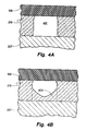
- FIGs. 4A and 4B are cross sectional elevation views of an ink feed channel which illustrate the effect of barrier layer bridging.
- FIG. 1 A typical inkjet cartridge is shown in FIG. 1, in which a cartridge body member 101 houses a supply of ink and routes the ink to a printhead 103 via ink conduits. Visible at the outer surface of the printhead are a plurality of orifices 105 through which ink is selectively expelled upon commands of the printer (not shown), which commands are communicated to the printhead 103 through electrical connections 107 and associated conductive traces (not shown).
- the printhead is constructed from a semiconductor substrate, including their film heater resistors disposed on or in the substrate, a photo definable barrier and adhesive layer, and a foraminous orifice plate which has a plurality of orifices extending entirely through the orifice plate and exemplified by orifice 105.
- Physical and electrical connections are made to a flexible polymer tape 109 by way of beam lead bonding or similar semiconductor technology which is subsequently secured by an epoxy-like material for physical strength and fluid rejection.
- the polymer tape 109 may be formed of KaptonTM, commercially available from 3M Corporation, or similar material which may be photoablated or chemically etched to produce openings and other desirable characteristics. Copper or other conductive traces are deposited or otherwise secured on one side of the tape so that electrical interconnections 107 can be contacted with the printer and routed to the substrate.
- the tape is typically bent around an edge of the print cartridge as shown and secured.
- FIG. 2 A cross section of the printhead is shown in FIG. 2 and is taken from part of the section A-A shown in FIG. 1.
- a portion of the body 201 of the cartridge 101 is shown where it is secured to the printhead by an adhesive in association with pressure.
- ink is supplied to the printhead by way of a common ink plenum 205 and through a slot 206 in the printhead substrate 207. (Alternatively, the ink may be supplied along the sides of the substrate).
- Heater resistors and their associated orifices are conventionally arranged in two essentially parallel rows near the inlet of ink from the ink plenum.
- the heater resistors and orifices are arranged in a staggered configuration in each row and, in the preferred embodiment, the heater resistors are located on opposite sides of the slot 206 of the substrate 207, as exemplified by heater resistors 209 and 211 in FIG. 2.
- the orifice plate 203 is produced by electrodepositing nickel on a mandrel having pegs and dikes with appropriate dimensions and suitable draft angles in the form of a couplement of the features desired in the orifice plate so that upon completion of a predetermined amount of time a thickness of nickel has been deposited.
- the resultant nickel film is removed after cooling and then mechanically planarized and treated for subsequent use.
- the nickel orifice plate is thn coated with a precious metal such as gold, paladium, or rhodium to resist corrosion. Following its fabrication, the orifice plate is affixed to the semiconductor substrate 207 with a barrier layer 213.
- the orifices created by the electrodeposition on the mandrel extend from the outside surface of the orifice plate 109 through the material to the inside surface, the surface which forms one of the walls of the ink firing chamber.
- an orifice is aligned directly over the heater resistor so that ink may be expelled from the orifice without a trajectory error introduced by an offset.
- the substrate 207 and orifice plate 109 are affixed together by a barrier layer material 213.
- the barrier layer material 213 is disposed on the substrate 207 in a pattemed formation such that firing chambers 215 and 217 are created in areas around the heater resistors.
- the barrier layer material is also pattemed so that ink is supplied independently to the firing chambers by one or more ink feed channels. Ink drops 219 are selectively ejected upon the rapid heating of a heater resistor upon command by the printer.
- the substrate having the barrier layer affixed to one surface is then positioned with respect to the orifice plate such that the orifices are precisely aligned with the heater resistors of the substrate.
- the barrier layer 213, in the preferred embodiment, utilizes a polymeric photodefinable material such as ParadTM, VacrelTM, IJ5000, or other materials which are a film negative photosensitive, multi-component, polymeric dry film which polymerizes with exposure to light or similar electromagnetic radiation. Materials of this sort are available from DuPont of Wilmington, Delaware.
- the barrier layer is first applied as a continuous layer upon the substrate 207 with the application of sufficient pressure and heat suitable for the particular material selected. Generally, the barrier layer film sandwiched between protective sheets of mylar. One sheet is removed to enable lamination of the barrier layer to the substrate. The other mylar sheet is left in place until the barrier layer is exposed.
- the photolithographic layer is exposed through a negative mask to ultraviolet light (preferably in the range of wavelengths of 440-340nm) to polymerize the barrier layer material.
- the exposed barrier layer is then subjected to a chemical wash using a developer solvent of a 74:26 w/w% mixture of N-methyl-2-pyrrolidone and diethylene glycol so that the unexposed areas of the barrier layer are removed by chemical action.
- the remaining areas of barrier layer form the walls of each ink firing chamber around each heater resistor.
- the remaining areas of barrier layer form the walls of ink feed channels which lead from the ink firing chamber to a source of ink (such as the ink plenum 205 by way of the slot as shown in FIG. 2).
- ink feed channels enable the initial fill of the ink firing chamber with ink and provide a continuous refill of the firing chamber after each expulsion of ink from the chamber.
- the rate at which ink can enter and fill the ink firing chamber is a significant factor in determining the highest speed at which the printer can print.
- two ink feed channels are created in the barrier layer to couple the ink plenum to the ink firing chamber so that a redundant supply of ink is maintained to the chamber and that a high rate of refill can be realized without having a significant part of the energy created for the ink bubble vaporization being lost from the ink feed channels.
- a lamination of orifice plate to the barrier layer is accomplished with the application of heat (approximately 200°) and pressure (between 50 and 250 psi.) for a period of time up to 15 minutes in the preferred embodiment.
- Adhesion promoters such as those disclosed in the U.S. Patentent Application No. 08/742,118, filed on behalf of Garold Radke et al. On October 1, 1996, may be employed to enhance the bond between the orifice plate and barrier layer.
- a final set-up of the polymer and cure of the bond is then accomplished with a thermal soak at approximately 220° for approximately 30 minutes.
- barrier layer of the preferred embodiment At the entrance to each ink feed channel there is disposed a plurality of barrier layer islands 301 such as shown in the isometric plan view of the surface of the substrate (with the orifice plate removed) of FIG. 3.
- Each barrier island is composed of barrier material and extends the full thickness of the barrier layer 213 from the substrate 207 to the orifice plate.
- each barrier island offers an area of adhesion of approximately 200 ⁇ m 2 to each surface.
- the major purpose of these barrier islands is to prevent particles and contaminants from the ink from reaching the ink feed channels and the orifice of each firing chamber.
- the dimensions of many of the elements of the printhead have been made significantly smaller than previously known designs to produce a high quality of ink printing by using small ink drops.
- the nominal ink drop weight is approximately 10 ng for ejection from an orifice having a bore diameter of 18 ⁇ m ( ⁇ 2 ⁇ m).
- two offset ink feed channels 303, 305 are employed to provide redundant ink refill capability.
- Each ink feed channel has a channel width W of 17 ⁇ m ( ⁇ 2 ⁇ m) and a channel length of approximately 30 ⁇ m.
- Channels and orifices of these dimensions present a greater challenge to the filtering of contaminants than previously undertaken in that particles the size of human skin cells will block an ink feed channel or orifice. Since particles of this size include some beiological cells which are non-rigid, the filter pore size must be less than the smallest operational dimension of the printhead to trap the potentially blocking particle. Depending upon the particular application, the smallest operational dimension is either the ink feed channel, w, of 17 ⁇ m ( ⁇ 2 ⁇ m) or the orifice bore diameter of approximately 18 ⁇ m. In the preferred embodiment, the spacing (S) between each island is 12 ⁇ m ( ⁇ 0.5 ⁇ m). The thickness of the barrier layer is 14 ⁇ m ( ⁇ 1.5 ⁇ m).
- Negative photoresists are well-known for resolution limitations primarily due to swelling during the materila photo development process. It is known that any feature defined in the barrier layer, or the space between any such feature, should have dimensions which exceed the thickness dimension of the barrier layer. See, Weiss, "Photoresist Technology Update", Semiconductor Intemational, April 1983, which states that negative photoresist materials are limited to layer thickness to feature dimensions of 1:2 or 1:3 ratios while positive resists were capable of 1:1 ratios.
- An example of a desired ink feed channel cross section is shown in FIG. 4A.
- the substrate 207 has the barrier layer 213 disposed on its surface. Orifice plate 109 is secured to the barrier layer 213.
- the barrier layer has had a channel 401 photodefined and developed into the barrier layer so that an ink feed channel has been created by the sandwich of substrate, barrier layer, and orifice plate.
- a bridge 403 of barrier layer remains across the narrow channel as shown in FIG. 4B. This bridge occludes the channel and reduces the volume of ink flow to the ink firing chamber.
- the barrier layer thickness is greater than the width of the feature being developed and the feature is in close proximity to a large volume of barrier material, bridging of the feature is expected to occur.
- the feature has a width dimension less than the barrier layer thickness but is at a distance from large volumes of barrier material, bridging does not occur for widths less than the barrier thickness but greater than 0.6 the barrier layer thickness at the exposure energy used for defining the rest of the pattern. The distance the feature must be separated from the large volume of exposedmaterial by a factor of 2 to 5 the barrier layer thickness depending upon the acutal size of the large volume of exposed material.
- the islands 301 are spaced apart from the nearest volume of barrier layer by a distance (D) of 10 ⁇ m ( ⁇ 0.25 ⁇ m).
- D the dimensions for the barrier layer features are given as the dimensions of the photo-resist mask.
- the spacings between barrier layer walls, spacings such as 5, the barrier island spacing, and w, the ink feed channel width, are expected to become between 1 and 2 ⁇ m larger than the photoresist mask dimensions.
- the placement of islands of barrier layer between the ink supply and the ink feed channels to the firing chamber and separated by a distance smaller than the width of the ink feed channel or the diameter of the orifice bore will diminish the blocking of the ink feed channel or the orifice bore by contaminants in the ink.
- the dimensions of the spaces between the islands is less than the thickness of the barrier layer, bridging between the islands is precluded by spacing the islands away from the rest of the barrier layer material.
Abstract
Description
- The present invention is generally related to a printhead for an inkjet printer and more particularly related to a printhead employing a particle tolerant ink feed filter of small dimensions to reduce particle blockages while maintaining a high rate of ink filling.
- Inkjet printers operate by expelling a small volume of ink through a plurality of small orifices in a surface held in proximity to a medium upon which marks or printing is to be placed. These orifices are arranged in a fashion in the surface such that the expulsion of a drop of ink from a selected number of orifices relative to a particular position of the medium results in the production of a portion of a desired character or image. Controlled repositioning of the orifice-bearing surface or the medium followed by another expulsion of ink drops results in the creation of more segments of the desired character or image. Furthermore, inks of various colors may be coupled to individual arrangements of orifices so that selected firing of the orifices can produce a multicolored image by the inkjet printer.
- Several mechanisms have been employed to create the force necessary to expel an ink drop from a printhead, among which are thermal, piezoelectric, and electrostatic mechanisms. While the following explanation is made with reference to the thermal ink expulsion mechanism, the present invention has application for the other ink expulsion mechanisms as well.
- Expulsion of the ink drop in a conventional thermal inkjet printer is a result of rapid thermal heating of the ink to a temperature which exceeds the boiling point of the ink solvent to create a vapor phase bubble of ink. Rapid heating of the ink is generally achieved by passing a pulse of electric current through an ink ejector which is an individually addressable heater resistor, typically for 1 to 3 microseconds, and the heat generated thereby is coupled to a small volume of ink held in an enclosed area which is generally referred to as a firing chamber. One of the enclosing walls of the firing chamber is formed by the surface which is penetrated by the plurality of orifices. One of the orifices in this orifice plate is arranged in relation to the heater resistor in a manner which enables ink to be expelled from the orifice. As the ink vapor bubble nucleates at the heater resistor and expands, it displaces a volume of ink which forces an equivalent volume of ink out of the orifice for deposition on the medium. The bubble then collapses and the displaced volume of ink is replenished from a larger ink reservoir by way of an ink feed channel in one of the walls of the firing chamber.
- It is desirable to have the ink refill the chamber as quickly as possible, thereby enabling very rapid firing of the orifices of the printhead. Rapid firing of the orifices results in the ability to achieve high-speed printing in an inkjet printer. Before the next firing of the heater resistor, the ink must have sufficient time to refill the chamber so that an undesirable variation in the size of the ink drop will not occur. Thus, one limitation on the speed at which printing may occur is related to the speed at which the firing chamber is refilled.
- A problem that occasionally manifests itself in inkjet printheads is that of blockage occurring in an ink feed channel or in the orifice of the printhead. Microscopic particles can become lodged in the channel leading to the ink firing chamber thereby causing premature failure of the heater resistor, misdirection of ink drops, or diminished ink supply to the firing chamber resulting in greatly diminished ink drop size. A single orifice which does not fire an ink drop when it is commanded to do so leaves a missing portion from a printed character or creates a band of missing drops from a printed image. The end result is perceived as a poorer quality of printed matter, a highly undesirable characteristic for an inkjet printer. To resolve this undesirable result, others have suggested using spare or redundant orifices to eject ink in place of defective ink ejectors (see, for example, U.S. Patent Nos. 4,963,882 and 5,640,183) or multiple inlets to the ink firing chamber.
- Ink for inkjet printing is conventionally stored in a reservoir associated with the printhead mechanism. The apparatus for storing ink, such as a porous foam material or a sealed container, is known to shed particles, which can plug ink feed channels or ejection orifices. It has been observed that many of the particles are elongate, fibrous particles which are undesired products of the manufacturing process. The fibrous particles occasionally disengage from the ink containment apparatus and are carried by the ink to the printhead despite special cleaning processes and ink filtering which occurs prior to the ink entering the printhead (such as that described in U.S. Patent Nos. 4,771,295 and 5,025,271). The filtering of elongate particles has been addressed in U.S. Patent Application No. 08/500,796, "Particle Tolerant Inkjet Printhead Architecture", filed on behalf of Timothy Weber et al. on July 11, 1995, in which a plurality of outer barrier islands prevent elongate particles from reaching the ink feed channels or the ink firing chamber. Ink filtering has also been disclosed in U.S. Patent No. 5,463,413 in which a plurality of pillars is arranged between the ink reservoir and the firing chamber, each pillar associated with the entrance to a firing chamber. The pillars are spaced apart by a distance less than or equal to the smallest dimension of the system, and are placed as close as possible to a common ink source to prevent particles from entering the firing chamber. The smallest dimension of the system is likely to be either the orifice bore diameter or the width of the passageway connecting the source of ink to the firing chamber.
- As the dimensions of the orifices, firing chambers, and ink feed channels are reduced in order to provide improved printing characteristics, the size of the particles which, because of their small size, have passed through the ink feed channels and have been expelled from the orifices of previous designs, can now clog the printhead. In a design which employs orifices or ink feed channels having dimensions smaller than 20 µm, particles and contaminants such as skin cells become candidates for lodging in the ink feed channel or orifice. Furthermore, particles such as skin and other biological cells are not rigid and therefore can deform and pass through a filter having a pore size equal to the smallest dimension in the printhead. Previous attempts to control and filter particles, while well suited for larger particles, do not solve the problem of clogging of the smaller passageways by the smaller particles.
- A printhead which ejects ink from at least one firing chamber for an inkjet printer includes a substrate with an ink ejector disposed thereon. A barrier layer is disposed on at least a portion of the substrate, has a thickness of a first dimension, has at least one ink feed channel which couples ink from a source of ink to the firing chamber. The ink feed channel has walls that are formed by an elongated separation of the barrier layer, the substrate and an orifice plate. The elongated separation is defined by a width of a second dimension. The barrier layer includes a plurality of islands, each spaced apart from an adjacent island by no more than a third dimension and disposed between the source of ink and the at least one ink feed channel. The second dimension is equal to or greater than the first dimension and the third dimension is less than the first dimension.
- FIG. 1 is an isometric view of an inkjet printer printhead.
- FIG. 2 is a cross sectional elevation view of the printhead which may be employed in the inkjet print cartridge of FIG. 1.
- FIG. 3 is an isometric plan view of the barrier layer and substrate of a printhead which may employ the present invention.
- FIGs. 4A and 4B are cross sectional elevation views of an ink feed channel which illustrate the effect of barrier layer bridging.
- A typical inkjet cartridge is shown in FIG. 1, in which a
cartridge body member 101 houses a supply of ink and routes the ink to aprinthead 103 via ink conduits. Visible at the outer surface of the printhead are a plurality oforifices 105 through which ink is selectively expelled upon commands of the printer (not shown), which commands are communicated to theprinthead 103 throughelectrical connections 107 and associated conductive traces (not shown). In one implementation of an inkjet print cartridge, the printhead is constructed from a semiconductor substrate, including their film heater resistors disposed on or in the substrate, a photo definable barrier and adhesive layer, and a foraminous orifice plate which has a plurality of orifices extending entirely through the orifice plate and exemplified byorifice 105. Physical and electrical connections are made to aflexible polymer tape 109 by way of beam lead bonding or similar semiconductor technology which is subsequently secured by an epoxy-like material for physical strength and fluid rejection. Thepolymer tape 109 may be formed of Kapton™, commercially available from 3M Corporation, or similar material which may be photoablated or chemically etched to produce openings and other desirable characteristics. Copper or other conductive traces are deposited or otherwise secured on one side of the tape so thatelectrical interconnections 107 can be contacted with the printer and routed to the substrate. The tape is typically bent around an edge of the print cartridge as shown and secured. - A cross section of the printhead is shown in FIG. 2 and is taken from part of the section A-A shown in FIG. 1. A portion of the
body 201 of thecartridge 101 is shown where it is secured to the printhead by an adhesive in association with pressure. In the preferred embodiment, ink is supplied to the printhead by way of acommon ink plenum 205 and through aslot 206 in theprinthead substrate 207. (Alternatively, the ink may be supplied along the sides of the substrate). Heater resistors and their associated orifices are conventionally arranged in two essentially parallel rows near the inlet of ink from the ink plenum. In many instances the heater resistors and orifices are arranged in a staggered configuration in each row and, in the preferred embodiment, the heater resistors are located on opposite sides of theslot 206 of thesubstrate 207, as exemplified byheater resistors - The
orifice plate 203 is produced by electrodepositing nickel on a mandrel having pegs and dikes with appropriate dimensions and suitable draft angles in the form of a couplement of the features desired in the orifice plate so that upon completion of a predetermined amount of time a thickness of nickel has been deposited. The resultant nickel film is removed after cooling and then mechanically planarized and treated for subsequent use. The nickel orifice plate is thn coated with a precious metal such as gold, paladium, or rhodium to resist corrosion. Following its fabrication, the orifice plate is affixed to thesemiconductor substrate 207 with abarrier layer 213. The orifices created by the electrodeposition on the mandrel extend from the outside surface of theorifice plate 109 through the material to the inside surface, the surface which forms one of the walls of the ink firing chamber. Usually, an orifice is aligned directly over the heater resistor so that ink may be expelled from the orifice without a trajectory error introduced by an offset. - The
substrate 207 andorifice plate 109 are affixed together by abarrier layer material 213. In the preferred embodiment, thebarrier layer material 213 is disposed on thesubstrate 207 in a pattemed formation such that firingchambers - The
barrier layer 213, in the preferred embodiment, utilizes a polymeric photodefinable material such as Parad™, Vacrel™, IJ5000, or other materials which are a film negative photosensitive, multi-component, polymeric dry film which polymerizes with exposure to light or similar electromagnetic radiation. Materials of this sort are available from DuPont of Wilmington, Delaware. The barrier layer is first applied as a continuous layer upon thesubstrate 207 with the application of sufficient pressure and heat suitable for the particular material selected. Generally, the barrier layer film sandwiched between protective sheets of mylar. One sheet is removed to enable lamination of the barrier layer to the substrate. The other mylar sheet is left in place until the barrier layer is exposed. The photolithographic layer is exposed through a negative mask to ultraviolet light (preferably in the range of wavelengths of 440-340nm) to polymerize the barrier layer material. The exposed barrier layer is then subjected to a chemical wash using a developer solvent of a 74:26 w/w% mixture of N-methyl-2-pyrrolidone and diethylene glycol so that the unexposed areas of the barrier layer are removed by chemical action. The remaining areas of barrier layer form the walls of each ink firing chamber around each heater resistor. Also, the remaining areas of barrier layer form the walls of ink feed channels which lead from the ink firing chamber to a source of ink (such as theink plenum 205 by way of the slot as shown in FIG. 2). These ink feed channels enable the initial fill of the ink firing chamber with ink and provide a continuous refill of the firing chamber after each expulsion of ink from the chamber. The rate at which ink can enter and fill the ink firing chamber is a significant factor in determining the highest speed at which the printer can print. In the preferred embodiment, two ink feed channels are created in the barrier layer to couple the ink plenum to the ink firing chamber so that a redundant supply of ink is maintained to the chamber and that a high rate of refill can be realized without having a significant part of the energy created for the ink bubble vaporization being lost from the ink feed channels. - A lamination of orifice plate to the barrier layer is accomplished with the application of heat (approximately 200°) and pressure (between 50 and 250 psi.) for a period of time up to 15 minutes in the preferred embodiment. Adhesion promoters, such as those disclosed in the U.S. Patentent Application No. 08/742,118, filed on behalf of Garold Radke et al. On October 1, 1996, may be employed to enhance the bond between the orifice plate and barrier layer. A final set-up of the polymer and cure of the bond is then accomplished with a thermal soak at approximately 220° for approximately 30 minutes.
- One additional feature is created in the barrier layer of the preferred embodiment. At the entrance to each ink feed channel there is disposed a plurality of
barrier layer islands 301 such as shown in the isometric plan view of the surface of the substrate (with the orifice plate removed) of FIG. 3. Each barrier island is composed of barrier material and extends the full thickness of thebarrier layer 213 from thesubstrate 207 to the orifice plate. In order to avoid delamination of the islands from either the orifice plate or the substrate, each barrier island offers an area of adhesion of approximately 200 µm2 to each surface. The major purpose of these barrier islands is to prevent particles and contaminants from the ink from reaching the ink feed channels and the orifice of each firing chamber. In order to function properly, this filter requires that the spaces (S) between each island (the equivalent of filter pores) be smaller than the channel width (W) of each firing chamber and smaller than the diameter of the orifice bore. Thus, any contaminant which could lodge in the ink feed channel or in the orifice is blocked from these critical areas. As a result of a number of islands (and spaces between), the blockage of any one of the spaces between the islands does not seriously impede the flow of ink to each ink feed channel and the likelihood of occlusion of an ink firing chamber is considerably reduced filter. Experiments with various spacing dimensions (S=10, 12, and 14µm) has demonstrated that at high rates of ink firing chamber refill, the performance of the printhead is unaffected by this range of dimensions. - In the preferred embodiment, the dimensions of many of the elements of the printhead have been made significantly smaller than previously known designs to produce a high quality of ink printing by using small ink drops. The nominal ink drop weight is approximately 10 ng for ejection from an orifice having a bore diameter of 18 µm (±2µm). In order to achieve an ink firing chamber refill rate supportive of a 15KHz frequency of operation, two offset
ink feed channels - Negative photoresists are well-known for resolution limitations primarily due to swelling during the materila photo development process. It is known that any feature defined in the barrier layer, or the space between any such feature, should have dimensions which exceed the thickness dimension of the barrier layer. See, Weiss, "Photoresist Technology Update", Semiconductor Intemational, April 1983, which states that negative photoresist materials are limited to layer thickness to feature dimensions of 1:2 or 1:3 ratios while positive resists were capable of 1:1 ratios. An example of a desired ink feed channel cross section is shown in FIG. 4A. The
substrate 207 has thebarrier layer 213 disposed on its surface.Orifice plate 109 is secured to thebarrier layer 213. The barrier layer has had achannel 401 photodefined and developed into the barrier layer so that an ink feed channel has been created by the sandwich of substrate, barrier layer, and orifice plate. When the width dimension of the channel is less than the thickness dimension of the barrier layer, incomplete development occurs and abridge 403 of barrier layer remains across the narrow channel as shown in FIG. 4B. This bridge occludes the channel and reduces the volume of ink flow to the ink firing chamber. - It has been determined that the depletion of dissolved oxygen during exposure limits the channel width that can be defined between large features. For a given barrier thickness, exposure dose, dose rate, temperature, and oxygen availability at the barrier surface, oxygen diffusion is believed to be limited to a finite distance. When barrier thickness is such that a channel is defined within this distance, the oxygen diffusion proximity effect becomes more important than swelling in limiting aspect ratio.
- When an area of barrier layer material is exposed to ionizing ratiation, chemical reactions are induced in the barrier film that form free radicals such as peroxy radicals. Theres free radicals combine to form crosslinking reactions that make exposed areas immune to the developer solvent and thus define the desired image; however, in a usual manufacturing environment, diatomic oxygen from the air is in equilibrium with the other components in the barrier layer film. Before the crosslinking reactions may ensue, the oxygen molecules - which are much more reactive to free radicals - must first be quenched. Once the amount of radiation required to react with the immedicately-available oxygen is exceeded, further radiation cross-links the material.
- The proximity effect that caused "incomplete development" (or "bridging") occurs at the interface between the exposed and unexposed areas of barrier: the exposed side has been dpleted of oxygen molecules; the unexposed side still has the equilibrium concentration. Thus, because the barrier layer film is separated from the oxygen in the air by its mylar cover film, an instanteous concentration gradient forces migration of oxygen molecules into the exposed area from the adjacent unexposed barrier in order to equalize the distribution of oxygen. Oxygen migration out of the unexposed channel then lowers the amount of radiation required to expose the barrier because there are fewer oxygen molecules to quench before the onset of crosslinking, thus allowing the masked channel to be undesirably exposed by radiation scattered from the unmasked area. Thus, in an inkjet printhead, when the barrier layer thickness is greater than the width of the feature being developed and the feature is in close proximity to a large volume of barrier material, bridging of the feature is expected to occur. However, when the feature has a width dimension less than the barrier layer thickness but is at a distance from large volumes of barrier material, bridging does not occur for widths less than the barrier thickness but greater than 0.6 the barrier layer thickness at the exposure energy used for defining the rest of the pattern. The distance the feature must be separated from the large volume of exposedmaterial by a factor of 2 to 5 the barrier layer thickness depending upon the acutal size of the large volume of exposed material. Accordingly, in the preferred embodiment of the present invention, the
islands 301 are spaced apart from the nearest volume of barrier layer by a distance (D) of 10 µm (±0.25µm). It should be noted that the dimensions for the barrier layer features are given as the dimensions of the photo-resist mask. The spacings between barrier layer walls, spacings such as 5, the barrier island spacing, and w, the ink feed channel width, are expected to become between 1 and 2µm larger than the photoresist mask dimensions. - Thus, the placement of islands of barrier layer between the ink supply and the ink feed channels to the firing chamber and separated by a distance smaller than the width of the ink feed channel or the diameter of the orifice bore will diminish the blocking of the ink feed channel or the orifice bore by contaminants in the ink. When the dimensions of the spaces between the islands is less than the thickness of the barrier layer, bridging between the islands is precluded by spacing the islands away from the rest of the barrier layer material.
Claims (6)
- A printhead which ejects ink from at least one firing chamber for an inkjet printer comprising:a substrate (207) having an ink ejector (209, 211) disposed thereon;a barrier layer (213) disposed on at least a portion of said substrate, said barrier layer including:a layer thickness of a first dimension,at least one ink feed channel (303, 305) by which ink is coupled from a source of ink to the firing chamber, said at least one ink feed channel having walls formed by an elongated separation of said barrier layer, said substrate, and an orifice plate (203), said elongated separation defined by a width (w) of a second dimension, anda plurality of islands (301), each island of said plurality of islands spaced apart from an adjacent island by no more than a third dimension (S) and disposed between said source of ink and said at least one ink feed channel; andwherein said second dimension is equal to or greater than said first dimension and said third dimension is less than said first dimension.
- A printhead in accordance with claim 1 wherein said orifice plate is disposed on said barrier layer and has an orifice (215, 217) therethrough, extending from a surface of said orifice plate nearest barrier layer to an external surface of said orifice plate and positioned relative to said ink ejector whereby ink may be expelled by said ink ejector.
- A printhead in accordance with claim 2 wherein said orifice plate further comprises said orifice having a minimum bore dimension greater than said first dimension.
- A method of manufacture of a printhead which ejects ink from at least one firing chamber for an inkjet printer, comprising the steps of:disposing a barrier layer (213) having a thickness of a first dimension on a portion on a substrate (207);exposing a predetermined portion of said barrier layer to electromagnetic radiation, said predetermined portion including walls of an ink feed channel (303, 305) which couples ink from a source of ink to the firing chamber and spaced apart from each other by a second dimension (w), and a plurality of islands (301), each island of siad plurality of islands spaced apart from an adjacent island of said plurality of islands by no more than a third dimension (S) and disposed between said souce of ink and said ink feed channel, said second dimension being equal to or greater than said first dimension and said third dimension being less than said first dimension; anddeveloping said barrier layer to remove portions of said barrier layer not exposed to electromagnetic radiation.
- A method in accordance with the method of claim 4 further comprising the steps of:creating at least one orifice (215, 217) in an orifice plate (203), said orifice extending from a first surface of said orifice plate to a second surface of said orifice plate and having a bore of a fourth dimension; anddisposing said orifice plate on said barrier layer, whereby ink may be expelled by said ink ejector through said created orifice.
- A method in accordance with the method of claim 5 further comprising the step of creating said bore fourth dimension greater than said first dimension.
Applications Claiming Priority (2)
| Application Number | Priority Date | Filing Date | Title |
|---|---|---|---|
| US904060 | 1997-07-31 | ||
| US08/904,060 US6007188A (en) | 1997-07-31 | 1997-07-31 | Particle tolerant printhead |
Publications (3)
| Publication Number | Publication Date |
|---|---|
| EP0894626A2 true EP0894626A2 (en) | 1999-02-03 |
| EP0894626A3 EP0894626A3 (en) | 1999-09-01 |
| EP0894626B1 EP0894626B1 (en) | 2002-03-13 |
Family
ID=25418478
Family Applications (1)
| Application Number | Title | Priority Date | Filing Date |
|---|---|---|---|
| EP98305718A Expired - Lifetime EP0894626B1 (en) | 1997-07-31 | 1998-07-17 | Printhead with a particle tolerant filter |
Country Status (5)
| Country | Link |
|---|---|
| US (1) | US6007188A (en) |
| EP (1) | EP0894626B1 (en) |
| KR (1) | KR100491934B1 (en) |
| DE (1) | DE69804171T2 (en) |
| TW (1) | TW442400B (en) |
Cited By (1)
| Publication number | Priority date | Publication date | Assignee | Title |
|---|---|---|---|---|
| WO2012134781A1 (en) * | 2011-03-30 | 2012-10-04 | Eastman Kodak Company | Inkjet chamber and inlets for circulating flow |
Families Citing this family (25)
| Publication number | Priority date | Publication date | Assignee | Title |
|---|---|---|---|---|
| US6145963A (en) * | 1997-08-29 | 2000-11-14 | Hewlett-Packard Company | Reduced size printhead for an inkjet printer |
| US6293654B1 (en) * | 1998-04-22 | 2001-09-25 | Hewlett-Packard Company | Printhead apparatus |
| US6161923A (en) * | 1998-07-22 | 2000-12-19 | Hewlett-Packard Company | Fine detail photoresist barrier |
| RU2146621C1 (en) * | 1998-11-03 | 2000-03-20 | Самсунг Электроникс Ко., Лтд | Microinjector |
| US6331049B1 (en) | 1999-03-12 | 2001-12-18 | Hewlett-Packard Company | Printhead having varied thickness passivation layer and method of making same |
| US6270201B1 (en) * | 1999-04-30 | 2001-08-07 | Hewlett-Packard Company | Ink jet drop generator and ink composition printing system for producing low ink drop weight with high frequency operation |
| US6294317B1 (en) * | 1999-07-14 | 2001-09-25 | Xerox Corporation | Patterned photoresist structures having features with high aspect ratios and method of forming such structures |
| US6557971B1 (en) | 2000-08-22 | 2003-05-06 | Hewlett-Packard Company | Method for servicing an inkjet printhead |
| US6502927B2 (en) * | 2000-12-28 | 2003-01-07 | Canon Kabushiki Kaisha | Ink jet recording head having two or more pillars for each nozzle |
| US6666947B2 (en) * | 2001-01-31 | 2003-12-23 | Hewlett-Packard Development Company, L.P. | Method for producing an inkjet printhead element; and an inkjet printhead element |
| US6350018B1 (en) * | 2001-02-23 | 2002-02-26 | Hewlett-Packard Company | Ink jet drop ejection architecture for improved damping and process yield |
| US6364467B1 (en) | 2001-05-04 | 2002-04-02 | Hewlett-Packard Company | Barrier island stagger compensation |
| US7025894B2 (en) * | 2001-10-16 | 2006-04-11 | Hewlett-Packard Development Company, L.P. | Fluid-ejection devices and a deposition method for layers thereof |
| US6464343B1 (en) * | 2001-10-31 | 2002-10-15 | Hewlett-Packard Company | Ink jet printhead having thin film structures for improving barrier island adhesion |
| KR100446634B1 (en) * | 2002-10-15 | 2004-09-04 | 삼성전자주식회사 | Inkjet printhead and manufacturing method thereof |
| US7387370B2 (en) * | 2004-04-29 | 2008-06-17 | Hewlett-Packard Development Company, L.P. | Microfluidic architecture |
| US7293359B2 (en) * | 2004-04-29 | 2007-11-13 | Hewlett-Packard Development Company, L.P. | Method for manufacturing a fluid ejection device |
| US8043517B2 (en) * | 2005-09-19 | 2011-10-25 | Hewlett-Packard Development Company, L.P. | Method of forming openings in substrates and inkjet printheads fabricated thereby |
| US20090027457A1 (en) * | 2007-07-25 | 2009-01-29 | Clark Garrett E | Fluid ejection device |
| JP5294884B2 (en) * | 2008-02-08 | 2013-09-18 | キヤノン株式会社 | Liquid discharge head |
| US8371683B2 (en) | 2010-12-23 | 2013-02-12 | Palo Alto Research Center Incorporated | Particle removal device for ink jet printer |
| CN104470724B (en) * | 2012-07-24 | 2016-04-27 | 惠普发展公司,有限责任合伙企业 | There is the fluid ejection apparatus of particle tolerance film extension |
| WO2015116121A1 (en) * | 2014-01-31 | 2015-08-06 | Hewlett-Packard Development Company, L.P. | Ink property sensing on a printhead |
| KR102193259B1 (en) | 2015-02-27 | 2020-12-22 | 휴렛-팩커드 디벨롭먼트 컴퍼니, 엘.피. | Fluid ejection device with fluid feed holes |
| US10632747B2 (en) | 2016-10-14 | 2020-04-28 | Hewlett-Packard Development Company, L.P. | Fluid ejection device |
Citations (6)
| Publication number | Priority date | Publication date | Assignee | Title |
|---|---|---|---|---|
| US4771295A (en) | 1986-07-01 | 1988-09-13 | Hewlett-Packard Company | Thermal ink jet pen body construction having improved ink storage and feed capability |
| US4963882A (en) | 1988-12-27 | 1990-10-16 | Hewlett-Packard Company | Printing of pixel locations by an ink jet printer using multiple nozzles for each pixel or pixel row |
| US5025271A (en) | 1986-07-01 | 1991-06-18 | Hewlett-Packard Company | Thin film resistor type thermal ink pen using a form storage ink supply |
| US5463413A (en) | 1993-06-03 | 1995-10-31 | Hewlett-Packard Company | Internal support for top-shooter thermal ink-jet printhead |
| US5640183A (en) | 1994-07-20 | 1997-06-17 | Hewlett-Packard Company | Redundant nozzle dot matrix printheads and method of use |
| US5734399A (en) | 1995-07-11 | 1998-03-31 | Hewlett-Packard Company | Particle tolerant inkjet printhead architecture |
Family Cites Families (14)
| Publication number | Priority date | Publication date | Assignee | Title |
|---|---|---|---|---|
| US4394670A (en) * | 1981-01-09 | 1983-07-19 | Canon Kabushiki Kaisha | Ink jet head and method for fabrication thereof |
| US4502060A (en) * | 1983-05-02 | 1985-02-26 | Hewlett-Packard Company | Barriers for thermal ink jet printers |
| JP2656481B2 (en) * | 1987-02-13 | 1997-09-24 | キヤノン株式会社 | Inkjet recording head |
| CA1300974C (en) * | 1987-10-30 | 1992-05-19 | Kenneth E. Trueba | Hydraulically tuned channel architecture |
| US5291226A (en) * | 1990-08-16 | 1994-03-01 | Hewlett-Packard Company | Nozzle member including ink flow channels |
| EP0500068B1 (en) * | 1991-02-20 | 1996-10-16 | Canon Kabushiki Kaisha | Ink jet recording head, recording apparatus using same and method for manufacturing same |
| US5194877A (en) * | 1991-05-24 | 1993-03-16 | Hewlett-Packard Company | Process for manufacturing thermal ink jet printheads having metal substrates and printheads manufactured thereby |
| US5189787A (en) * | 1991-07-30 | 1993-03-02 | Hewlett-Packard Company | Attachment of a flexible circuit to an ink-jet pen |
| IT1250371B (en) * | 1991-12-24 | 1995-04-07 | Olivetti & Co Spa | PERFECTED INK JET PRINT HEAD. |
| US5278584A (en) * | 1992-04-02 | 1994-01-11 | Hewlett-Packard Company | Ink delivery system for an inkjet printhead |
| US5450109A (en) * | 1993-03-24 | 1995-09-12 | Hewlett-Packard Company | Barrier alignment and process monitor for TIJ printheads |
| JPH07164639A (en) * | 1993-12-14 | 1995-06-27 | Canon Inc | Ink jet recording head, manufacture thereof and recorder with the recording head |
| US5666143A (en) * | 1994-07-29 | 1997-09-09 | Hewlett-Packard Company | Inkjet printhead with tuned firing chambers and multiple inlets |
| JPH09164696A (en) * | 1995-10-31 | 1997-06-24 | Hewlett Packard Co <Hp> | Ink-jet printing cartridge |
-
1997
- 1997-07-31 US US08/904,060 patent/US6007188A/en not_active Expired - Lifetime
-
1998
- 1998-07-17 EP EP98305718A patent/EP0894626B1/en not_active Expired - Lifetime
- 1998-07-17 DE DE69804171T patent/DE69804171T2/en not_active Expired - Lifetime
- 1998-07-30 KR KR10-1998-0030825A patent/KR100491934B1/en not_active IP Right Cessation
- 1998-07-30 TW TW087112579A patent/TW442400B/en not_active IP Right Cessation
Patent Citations (8)
| Publication number | Priority date | Publication date | Assignee | Title |
|---|---|---|---|---|
| US4771295A (en) | 1986-07-01 | 1988-09-13 | Hewlett-Packard Company | Thermal ink jet pen body construction having improved ink storage and feed capability |
| US5025271A (en) | 1986-07-01 | 1991-06-18 | Hewlett-Packard Company | Thin film resistor type thermal ink pen using a form storage ink supply |
| US4771295B1 (en) | 1986-07-01 | 1995-08-01 | Hewlett Packard Co | Thermal ink jet pen body construction having improved ink storage and feed capability |
| US4963882A (en) | 1988-12-27 | 1990-10-16 | Hewlett-Packard Company | Printing of pixel locations by an ink jet printer using multiple nozzles for each pixel or pixel row |
| US4963882B1 (en) | 1988-12-27 | 1996-10-29 | Hewlett Packard Co | Printing of pixel locations by an ink jet printer using multiple nozzles for each pixel or pixel row |
| US5463413A (en) | 1993-06-03 | 1995-10-31 | Hewlett-Packard Company | Internal support for top-shooter thermal ink-jet printhead |
| US5640183A (en) | 1994-07-20 | 1997-06-17 | Hewlett-Packard Company | Redundant nozzle dot matrix printheads and method of use |
| US5734399A (en) | 1995-07-11 | 1998-03-31 | Hewlett-Packard Company | Particle tolerant inkjet printhead architecture |
Cited By (2)
| Publication number | Priority date | Publication date | Assignee | Title |
|---|---|---|---|---|
| WO2012134781A1 (en) * | 2011-03-30 | 2012-10-04 | Eastman Kodak Company | Inkjet chamber and inlets for circulating flow |
| US8449086B2 (en) | 2011-03-30 | 2013-05-28 | Eastman Kodak Company | Inkjet chamber and inlets for circulating flow |
Also Published As
| Publication number | Publication date |
|---|---|
| US6007188A (en) | 1999-12-28 |
| EP0894626A3 (en) | 1999-09-01 |
| DE69804171D1 (en) | 2002-04-18 |
| EP0894626B1 (en) | 2002-03-13 |
| KR100491934B1 (en) | 2005-08-04 |
| KR19990014299A (en) | 1999-02-25 |
| DE69804171T2 (en) | 2002-08-29 |
| TW442400B (en) | 2001-06-23 |
Similar Documents
| Publication | Publication Date | Title |
|---|---|---|
| EP0894626B1 (en) | Printhead with a particle tolerant filter | |
| US6264309B1 (en) | Filter formed as part of a heater chip for removing contaminants from a fluid and a method for forming same | |
| US6146915A (en) | Reduced size printhead for an inkjet printer | |
| US5734399A (en) | Particle tolerant inkjet printhead architecture | |
| EP0940257B1 (en) | Direct imaging polymer fluid jet orifice | |
| EP0895866B1 (en) | Forming refill slot for monolithic ink jet printhead | |
| EP2046582B1 (en) | Fluid ejection devices and methods of fabrication | |
| US6267251B1 (en) | Filter assembly for a print cartridge container for removing contaminants from a fluid | |
| JP4590451B2 (en) | Elongated filter assembly | |
| US6951383B2 (en) | Fluid ejection device having a substrate to filter fluid and method of manufacture | |
| US6161923A (en) | Fine detail photoresist barrier | |
| JPH068445A (en) | Ink jet printer printing head, method for forming ink jet printer printing head, and component assembling method therefor | |
| JP2002192723A (en) | Printer, method for forming the same, and printing method | |
| US6669336B1 (en) | Ink jet printhead having an integral internal filter | |
| US20020071006A1 (en) | Direct imaging polymer fluid jet orifice | |
| US6402296B1 (en) | High resolution inkjet printer | |
| CN113272146B (en) | Fluid feed hole port size |
Legal Events
| Date | Code | Title | Description |
|---|---|---|---|
| PUAI | Public reference made under article 153(3) epc to a published international application that has entered the european phase |
Free format text: ORIGINAL CODE: 0009012 |
|
| AK | Designated contracting states |
Kind code of ref document: A2 Designated state(s): DE FR GB |
|
| AX | Request for extension of the european patent |
Free format text: AL;LT;LV;MK;RO;SI |
|
| RIN1 | Information on inventor provided before grant (corrected) |
Inventor name: STOUT, JOE E. Inventor name: PIDWERBECKI, DAVID Inventor name: SMYTH, JOHN B. Inventor name: MACLEOD, CHERYL A. |
|
| PUAL | Search report despatched |
Free format text: ORIGINAL CODE: 0009013 |
|
| AK | Designated contracting states |
Kind code of ref document: A3 Designated state(s): AT BE CH CY DE DK ES FI FR GB GR IE IT LI LU MC NL PT SE |
|
| AX | Request for extension of the european patent |
Free format text: AL;LT;LV;MK;RO;SI |
|
| 17P | Request for examination filed |
Effective date: 19991028 |
|
| AKX | Designation fees paid |
Free format text: DE FR GB |
|
| GRAG | Despatch of communication of intention to grant |
Free format text: ORIGINAL CODE: EPIDOS AGRA |
|
| 17Q | First examination report despatched |
Effective date: 20010315 |
|
| RAP1 | Party data changed (applicant data changed or rights of an application transferred) |
Owner name: HEWLETT-PACKARD COMPANY, A DELAWARE CORPORATION |
|
| GRAG | Despatch of communication of intention to grant |
Free format text: ORIGINAL CODE: EPIDOS AGRA |
|
| GRAH | Despatch of communication of intention to grant a patent |
Free format text: ORIGINAL CODE: EPIDOS IGRA |
|
| GRAH | Despatch of communication of intention to grant a patent |
Free format text: ORIGINAL CODE: EPIDOS IGRA |
|
| REG | Reference to a national code |
Ref country code: GB Ref legal event code: IF02 |
|
| GRAA | (expected) grant |
Free format text: ORIGINAL CODE: 0009210 |
|
| AK | Designated contracting states |
Kind code of ref document: B1 Designated state(s): DE FR GB |
|
| REF | Corresponds to: |
Ref document number: 69804171 Country of ref document: DE Date of ref document: 20020418 |
|
| ET | Fr: translation filed | ||
| PLBE | No opposition filed within time limit |
Free format text: ORIGINAL CODE: 0009261 |
|
| STAA | Information on the status of an ep patent application or granted ep patent |
Free format text: STATUS: NO OPPOSITION FILED WITHIN TIME LIMIT |
|
| 26N | No opposition filed |
Effective date: 20021216 |
|
| REG | Reference to a national code |
Ref country code: GB Ref legal event code: 732E Free format text: REGISTERED BETWEEN 20120329 AND 20120404 |
|
| PGFP | Annual fee paid to national office [announced via postgrant information from national office to epo] |
Ref country code: FR Payment date: 20120731 Year of fee payment: 15 |
|
| PGFP | Annual fee paid to national office [announced via postgrant information from national office to epo] |
Ref country code: GB Payment date: 20130626 Year of fee payment: 16 |
|
| PGFP | Annual fee paid to national office [announced via postgrant information from national office to epo] |
Ref country code: DE Payment date: 20130621 Year of fee payment: 16 |
|
| REG | Reference to a national code |
Ref country code: FR Ref legal event code: ST Effective date: 20140331 |
|
| PG25 | Lapsed in a contracting state [announced via postgrant information from national office to epo] |
Ref country code: FR Free format text: LAPSE BECAUSE OF NON-PAYMENT OF DUE FEES Effective date: 20130731 |
|
| REG | Reference to a national code |
Ref country code: DE Ref legal event code: R119 Ref document number: 69804171 Country of ref document: DE |
|
| GBPC | Gb: european patent ceased through non-payment of renewal fee |
Effective date: 20140717 |
|
| PG25 | Lapsed in a contracting state [announced via postgrant information from national office to epo] |
Ref country code: DE Free format text: LAPSE BECAUSE OF NON-PAYMENT OF DUE FEES Effective date: 20150203 |
|
| REG | Reference to a national code |
Ref country code: DE Ref legal event code: R119 Ref document number: 69804171 Country of ref document: DE Effective date: 20150203 |
|
| PG25 | Lapsed in a contracting state [announced via postgrant information from national office to epo] |
Ref country code: GB Free format text: LAPSE BECAUSE OF NON-PAYMENT OF DUE FEES Effective date: 20140717 |