EP0889252A2 - An elongate element for transmitting forces - Google Patents
An elongate element for transmitting forces Download PDFInfo
- Publication number
- EP0889252A2 EP0889252A2 EP98109610A EP98109610A EP0889252A2 EP 0889252 A2 EP0889252 A2 EP 0889252A2 EP 98109610 A EP98109610 A EP 98109610A EP 98109610 A EP98109610 A EP 98109610A EP 0889252 A2 EP0889252 A2 EP 0889252A2
- Authority
- EP
- European Patent Office
- Prior art keywords
- transmitting forces
- forces according
- slot
- openings
- tube
- Prior art date
- Legal status (The legal status is an assumption and is not a legal conclusion. Google has not performed a legal analysis and makes no representation as to the accuracy of the status listed.)
- Granted
Links
Images
Classifications
-
- F—MECHANICAL ENGINEERING; LIGHTING; HEATING; WEAPONS; BLASTING
- F16—ENGINEERING ELEMENTS AND UNITS; GENERAL MEASURES FOR PRODUCING AND MAINTAINING EFFECTIVE FUNCTIONING OF MACHINES OR INSTALLATIONS; THERMAL INSULATION IN GENERAL
- F16C—SHAFTS; FLEXIBLE SHAFTS; ELEMENTS OR CRANKSHAFT MECHANISMS; ROTARY BODIES OTHER THAN GEARING ELEMENTS; BEARINGS
- F16C1/00—Flexible shafts; Mechanical means for transmitting movement in a flexible sheathing
-
- A—HUMAN NECESSITIES
- A61—MEDICAL OR VETERINARY SCIENCE; HYGIENE
- A61B—DIAGNOSIS; SURGERY; IDENTIFICATION
- A61B17/00—Surgical instruments, devices or methods, e.g. tourniquets
- A61B17/16—Bone cutting, breaking or removal means other than saws, e.g. Osteoclasts; Drills or chisels for bones; Trepans
- A61B17/1613—Component parts
- A61B17/1631—Special drive shafts, e.g. flexible shafts
-
- A—HUMAN NECESSITIES
- A61—MEDICAL OR VETERINARY SCIENCE; HYGIENE
- A61B—DIAGNOSIS; SURGERY; IDENTIFICATION
- A61B17/00—Surgical instruments, devices or methods, e.g. tourniquets
- A61B17/56—Surgical instruments or methods for treatment of bones or joints; Devices specially adapted therefor
- A61B17/58—Surgical instruments or methods for treatment of bones or joints; Devices specially adapted therefor for osteosynthesis, e.g. bone plates, screws, setting implements or the like
- A61B17/68—Internal fixation devices, including fasteners and spinal fixators, even if a part thereof projects from the skin
- A61B17/72—Intramedullary pins, nails or other devices
-
- F—MECHANICAL ENGINEERING; LIGHTING; HEATING; WEAPONS; BLASTING
- F16—ENGINEERING ELEMENTS AND UNITS; GENERAL MEASURES FOR PRODUCING AND MAINTAINING EFFECTIVE FUNCTIONING OF MACHINES OR INSTALLATIONS; THERMAL INSULATION IN GENERAL
- F16C—SHAFTS; FLEXIBLE SHAFTS; ELEMENTS OR CRANKSHAFT MECHANISMS; ROTARY BODIES OTHER THAN GEARING ELEMENTS; BEARINGS
- F16C1/00—Flexible shafts; Mechanical means for transmitting movement in a flexible sheathing
- F16C1/02—Flexible shafts; Mechanical means for transmitting movement in a flexible sheathing for conveying rotary movements
-
- A—HUMAN NECESSITIES
- A61—MEDICAL OR VETERINARY SCIENCE; HYGIENE
- A61B—DIAGNOSIS; SURGERY; IDENTIFICATION
- A61B17/00—Surgical instruments, devices or methods, e.g. tourniquets
- A61B17/00234—Surgical instruments, devices or methods, e.g. tourniquets for minimally invasive surgery
- A61B2017/00292—Surgical instruments, devices or methods, e.g. tourniquets for minimally invasive surgery mounted on or guided by flexible, e.g. catheter-like, means
- A61B2017/003—Steerable
- A61B2017/00305—Constructional details of the flexible means
- A61B2017/00309—Cut-outs or slits
-
- F—MECHANICAL ENGINEERING; LIGHTING; HEATING; WEAPONS; BLASTING
- F16—ENGINEERING ELEMENTS AND UNITS; GENERAL MEASURES FOR PRODUCING AND MAINTAINING EFFECTIVE FUNCTIONING OF MACHINES OR INSTALLATIONS; THERMAL INSULATION IN GENERAL
- F16C—SHAFTS; FLEXIBLE SHAFTS; ELEMENTS OR CRANKSHAFT MECHANISMS; ROTARY BODIES OTHER THAN GEARING ELEMENTS; BEARINGS
- F16C2316/00—Apparatus in health or amusement
- F16C2316/10—Apparatus in health or amusement in medical appliances, e.g. in diagnosis, dentistry, instruments, prostheses, medical imaging appliances
-
- Y—GENERAL TAGGING OF NEW TECHNOLOGICAL DEVELOPMENTS; GENERAL TAGGING OF CROSS-SECTIONAL TECHNOLOGIES SPANNING OVER SEVERAL SECTIONS OF THE IPC; TECHNICAL SUBJECTS COVERED BY FORMER USPC CROSS-REFERENCE ART COLLECTIONS [XRACs] AND DIGESTS
- Y10—TECHNICAL SUBJECTS COVERED BY FORMER USPC
- Y10T—TECHNICAL SUBJECTS COVERED BY FORMER US CLASSIFICATION
- Y10T428/00—Stock material or miscellaneous articles
- Y10T428/12—All metal or with adjacent metals
- Y10T428/12201—Width or thickness variation or marginal cuts repeating longitudinally
-
- Y—GENERAL TAGGING OF NEW TECHNOLOGICAL DEVELOPMENTS; GENERAL TAGGING OF CROSS-SECTIONAL TECHNOLOGIES SPANNING OVER SEVERAL SECTIONS OF THE IPC; TECHNICAL SUBJECTS COVERED BY FORMER USPC CROSS-REFERENCE ART COLLECTIONS [XRACs] AND DIGESTS
- Y10—TECHNICAL SUBJECTS COVERED BY FORMER USPC
- Y10T—TECHNICAL SUBJECTS COVERED BY FORMER US CLASSIFICATION
- Y10T428/00—Stock material or miscellaneous articles
- Y10T428/12—All metal or with adjacent metals
- Y10T428/12361—All metal or with adjacent metals having aperture or cut
Definitions
- the invention relates to an elongate element for transmitting forces, according to claim 1.
- a cable transmits tensile force (as a rubber cable or rubber band in an elastic manner) but not compressive force, transverse force, torsion and bending moments.
- a rigid beam transmits all known forces and moments, but however with respect to the cable does not for example offer the free deformability transversely to the extension direction, thus offer e.g. the possibility of changing the transmitted tensile force in its direction by way of redirecting via a roller.
- Elongate elements for transmitting forces in technical systems are used in a static or dynamic function: a shaft for example is per se a rotating, thus dynamically applied elongate element for transmitting torsional force.
- the already mentioned beam as part of a rod framework, for example in a scaffolding, is a statically applied elongate element which in particular transmits tensile and compressive force, but also accommodates bending moments in order to prevent buckling.
- Known elongate elements for transmitting forces in various spacial directions are essentially completely rigid or "slack", but only in a few embodiment forms are of a certain desired flexibility or elasticity (stiffness).
- this are the rubber cable already mentioned, which in its longitudinal direction has a certain rubber elasticity and in all other directions is slack.
- a further example is a so-called bending shaft which elastically accommodates bending moments about any axis perpendicular to its longitudinal axis and transmits torsion force about its longitudinal axis essentially rigidly.
- Bendable shafts are usually wound from wire and may be coated in order to keep the wire winding in its shape. In order to transmit torsional forces in both directions, it usually requires second oppositely wound wire layers.
- Such bendable shafts are accordingly manufactured from several parts, but are therefore expensive in their manufacture and furthermore are of a relatively small load capacity and life expectancy.
- a hollow elongate element for transmitting forces is of elastic material.
- the walling of the elongate element comprises openings in an arrangement which reduce the bending resistance moment of the element.
- the openings in the walling of the element are arranged such that the torsion resistance moment of the element remains essentially unchanged.
- the element may be cylindrical, preferably tubular. It permits as a one-piece design element a simple manufacture. It requires no lubrication or regular maintenance since there are no different parts which are mounted to one another or rub against one another.
- the openings may be arranged in a pattern recurrent in the longitudinal direction of the element. This is preferably spiral-shaped.
- a preferred embodiment form of the invention provides slots as openings which in each case extend transversally into the elongate element.
- the element with a cylindrical, preferably tubular cross section is transversally notched by each slot, wherein a region near to the edge, preferably a region of the tube walling of each notched cross section is not cut through by the slot.
- the slots are so displaced in the circumferential direction that the regions which are not cut through are arranged in the longitudinal direction of the element in a helical manner.
- each slot does not cut through only one web of the tube walling.
- the width of the slot dependent of the depth of the slot is preferably formed larger than the tubular wall thickness.
- the bending resistance moment of the element about this web of a larger width than height is smallest about that axis which lies parallel to the width of the web.
- the principle tension lines run spiral-shaped about the torsional axis.
- the openings are arranged in a pattern helical-shaped in the longitudinal direction of the element, also the webs which have not been cut through are arranged helical-shaped and form a helical-shaped uninterrupted material region which is in the position of transmitting principle torsional tensions without being weakened.
- the element preferably consists of a metallic material. Due to the variety of application possibilities in surgical technology, for example as an implant for the marrow nailing of the upper arm or as a bendable shaft for a marrow space drill, the element preferably consists of biocompatible material, in particular implant steel or titanium.
- Tension and compressive forces can be transmitted essentially rigidly on account of the one-pieced form of the element.
- the safety of the element against buckling may be set.
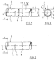
- an elongate element 2 for transmitting forces is formed as a tube with a tube outer diameter D and a tube thickness S.
- the walling 4 of the element 2 comprises slots 6 which with a width B and a depth T in each case transversally extend into the element 2. With this each slot 6 leaves a region 8 of the element, near to the edge, which is not cut through in the respective transversal cross section.
- the slots 6 are arranged next to one another at a distance to one another.
- each slot 6b is formed displaced to the neighbouring slot at an angle of 90° about the longitudinal axis 10 of the tube.
- the angle is 180°.
- the element 2 according to Fig. 1 is bendable about two axes which lie at right angles to the longitudinal axis 10 of the element 2 as well as at right angles to one another.
- the element 2 according to Fig. 2 is only bendable about one axis which lies at right angles to the longitudinal axis 19 of element 2.
- Both elements 2 according to Fig. 1 and 2 are for example the implant for bone marrow nailing the upper arm in that on introduction into the drilled out marrow space of the upper arm bone it may follow the curvature of this bone, which is determined by the anatomy.
- the element 2 may be proportioned as follows: the slots 6 have a distance A to one another of >5% and ⁇ 40% of the tube outer diameter D.
- the slots 6 have a width B of >20% and ⁇ 80% of the distance A to the neighbouring slot.
- the slots 6 are displaced to the neighbouring slot about an angle >20° and ⁇ 180° about the longitudinal axis 10 of the tube.
- Each slot 6 extends with a depth T of ⁇ 90% of the tube outer diameter D transversally into the element 2.
- the wall thickness S of the tubular element 2 is >5% of the tube outer diameter D.
Abstract
Description
- Fig. 1
- shows a lateral view of a cutout of an element for transmitting forces according to the invention.
- Fig. 2
- shows a lateral view of a cutout of a further element for transmitting forces.
- Fig. 3
- shows a section along the line X-Y through the elements in Fig. 1 and 2.
Claims (9)
- A hollow elongate element (2) of elastic material for transmitting forces wherein the wall (4) comprises openings (6) which reduce the bending resistance moment and are arranged such that the torsion resistance moment of the element is essentially maintained.
- The element for transmitting forces according to claim 1, wherein the element is cylindrical.
- The element for transmitting forces according to claim 1 or 2, wherein the element is tubular.
- The element for transmitting forces according to claim 1, wherein the openings (6) are arranged in a pattern recurrent in the longitudinal direction of the element (2).
- The element for transmitting forces according to claim 1, wherein the openings (6) are arranged in a pattern helical-shaped in the longitudinal direction of the element (2).
- The element for transmitting forces according to claim 1, wherein the openings are slots (6) which each extend transversally into the element (2) and of which each slot does not cut through a region (8) of the element, which is near to the edge, in the respective transversal cross section, and wherein the slots are formed offset to one another such that the regions (8) near to the edge are arranged helix-shaped in the longitudinal direction of the element (2).
- The element for transmitting forces according to claim 6, wherein the element (2) is tubular and has a tube wall thickness (S) >5% of the tube outer diameter (D) and wherein each slot is formed offset to the neighbouring slot at a distance (A) of >5% and <40% of the tube outer diameter (D) and about an angle >20° and ≤180° about the longitudinal axis 10 of the tube and extends transversally into the element (2) with a depth (T) of <90% of the tube outer diameter (D) and with a width (B) of >20% and <80% of the distance (A) to the neighbouring slot.
- The element for transmitting forces according to claim 1, wherein the element (2) consists of a metallic material.
- The element for transmitting forces according to claim 1, wherein the element (2) consists of a biocompatible material, in particular implant steel or titanium.
Applications Claiming Priority (2)
| Application Number | Priority Date | Filing Date | Title |
|---|---|---|---|
| DE29711559U DE29711559U1 (en) | 1997-07-02 | 1997-07-02 | Elongated element for the transmission of forces |
| DE29711559U | 1997-07-02 |
Publications (3)
| Publication Number | Publication Date |
|---|---|
| EP0889252A2 true EP0889252A2 (en) | 1999-01-07 |
| EP0889252A3 EP0889252A3 (en) | 1999-04-07 |
| EP0889252B1 EP0889252B1 (en) | 2003-04-02 |
Family
ID=8042480
Family Applications (1)
| Application Number | Title | Priority Date | Filing Date |
|---|---|---|---|
| EP98109610A Expired - Lifetime EP0889252B1 (en) | 1997-07-02 | 1998-05-27 | An elongate element for transmitting forces |
Country Status (7)
| Country | Link |
|---|---|
| US (1) | US6337142B2 (en) |
| EP (1) | EP0889252B1 (en) |
| JP (1) | JPH1176261A (en) |
| AT (1) | ATE236358T1 (en) |
| CA (1) | CA2240207C (en) |
| DE (2) | DE29711559U1 (en) |
| ES (1) | ES2194251T3 (en) |
Cited By (4)
| Publication number | Priority date | Publication date | Assignee | Title |
|---|---|---|---|---|
| DE10016633A1 (en) * | 2000-04-04 | 2001-10-11 | Alexander Joist | Semi-flexible shaft has a series of rigid sections linked by ball and socket joints with shoulder interface |
| US6337142B2 (en) | 1997-07-02 | 2002-01-08 | Stryker Trauma Gmbh | Elongate element for transmitting forces |
| WO2004057136A1 (en) * | 2002-12-19 | 2004-07-08 | Huf Hülsbeck & Fürst Gmbh & Co. Kg | Operating device for a lock for doors or bonnets on a motor vehicle |
| WO2013188133A1 (en) * | 2012-06-15 | 2013-12-19 | Trivascular, Inc. | Endovascular delivery system with flexible and torqueable hypotube |
Families Citing this family (74)
| Publication number | Priority date | Publication date | Assignee | Title |
|---|---|---|---|---|
| FR2812185B1 (en) * | 2000-07-25 | 2003-02-28 | Spine Next Sa | SEMI-RIGID CONNECTION PIECE FOR RACHIS STABILIZATION |
| FR2812186B1 (en) * | 2000-07-25 | 2003-02-28 | Spine Next Sa | FLEXIBLE CONNECTION PIECE FOR SPINAL STABILIZATION |
| US7882162B2 (en) * | 2002-08-08 | 2011-02-01 | Hewlett-Packard Development Company, L.P. | Rapid access to data on a powered down personal computer |
| DE10246501A1 (en) * | 2002-10-04 | 2004-04-15 | Dr.Ing.H.C. F. Porsche Ag | Door lock of a motor vehicle |
| US20050165366A1 (en) | 2004-01-28 | 2005-07-28 | Brustad John R. | Medical tubing having variable characteristics and method of making same |
| US20050004515A1 (en) * | 2002-11-15 | 2005-01-06 | Hart Charles C. | Steerable kink resistant sheath |
| DE20219683U1 (en) * | 2002-12-19 | 2004-04-29 | Stryker Trauma Gmbh | osteosynthesis |
| US20050015072A1 (en) * | 2003-07-15 | 2005-01-20 | Medtronic, Inc. | Cannula having buckle resistant apertures |
| US7763052B2 (en) * | 2003-12-05 | 2010-07-27 | N Spine, Inc. | Method and apparatus for flexible fixation of a spine |
| US20050203513A1 (en) * | 2003-09-24 | 2005-09-15 | Tae-Ahn Jahng | Spinal stabilization device |
| US7815665B2 (en) * | 2003-09-24 | 2010-10-19 | N Spine, Inc. | Adjustable spinal stabilization system |
| US8979900B2 (en) * | 2003-09-24 | 2015-03-17 | DePuy Synthes Products, LLC | Spinal stabilization device |
| US20050065516A1 (en) * | 2003-09-24 | 2005-03-24 | Tae-Ahn Jahng | Method and apparatus for flexible fixation of a spine |
| DE10348329B3 (en) * | 2003-10-17 | 2005-02-17 | Biedermann Motech Gmbh | Rod-shaped element used in spinal column and accident surgery for connecting two bone-anchoring elements comprises a rigid section and an elastic section that are made in one piece |
| US8632570B2 (en) | 2003-11-07 | 2014-01-21 | Biedermann Technologies Gmbh & Co. Kg | Stabilization device for bones comprising a spring element and manufacturing method for said spring element |
| KR101280591B1 (en) * | 2003-11-07 | 2013-07-02 | 비이더만 테크놀로지스 게엠베하 & 코. 카게 | Spring Element for a Bone Stabilizing Device, and Method for the Production of said Spring Element |
| EP1532931A1 (en) * | 2003-11-24 | 2005-05-25 | Stryker Trauma GmbH | Screwdriver with flexible shaft for bone screws |
| DE20318703U1 (en) * | 2003-11-24 | 2004-02-19 | Stryker Trauma Gmbh | Screwdriver for bone screws, in particular, compression and locking screws comprises a shaft which has a flexible section covered by a protective hose |
| US7909873B2 (en) * | 2006-12-15 | 2011-03-22 | Soteira, Inc. | Delivery apparatus and methods for vertebrostenting |
| FR2870718B1 (en) * | 2004-05-25 | 2006-09-22 | Spine Next Sa | TREATMENT ASSEMBLY FOR THE DEGENERATION OF AN INTERVERTEBRAL DISC |
| DE102004047805A1 (en) * | 2004-09-29 | 2006-03-30 | Altratec Montagesysteme Gmbh | Extruded aluminum or plastic profile has bendable zones with transverse slits which reduce their rigidity |
| DE102004048938B4 (en) * | 2004-10-07 | 2015-04-02 | Synthes Gmbh | Device for the dynamic stabilization of vertebral bodies |
| US20060276247A1 (en) * | 2005-06-03 | 2006-12-07 | Martinez Jaime E | Flexible shaft |
| US20070016190A1 (en) * | 2005-07-14 | 2007-01-18 | Medical Device Concepts Llc | Dynamic spinal stabilization system |
| US20070016204A1 (en) * | 2005-07-14 | 2007-01-18 | Medical Device Concepts Llc. | Spinal buttress device and method |
| US8083727B2 (en) | 2005-09-12 | 2011-12-27 | Bridgepoint Medical, Inc. | Endovascular devices and methods for exploiting intramural space |
| EP1924315B1 (en) | 2005-09-12 | 2019-12-04 | Bridgepoint Medical, Inc. | Endovascular devices |
| US7918870B2 (en) | 2005-09-12 | 2011-04-05 | Bridgepoint Medical, Inc. | Endovascular devices and methods |
| US8025655B2 (en) | 2005-09-12 | 2011-09-27 | Bridgepoint Medical, Inc. | Endovascular devices and methods |
| US11020141B2 (en) | 2005-09-12 | 2021-06-01 | Bridgepoint Medical, Inc. | Endovascular devices and methods |
| WO2007137184A2 (en) * | 2006-05-18 | 2007-11-29 | Applied Medical Resources Corporation | Method of making medical tubing having variable characteristics using thermal winding |
| WO2008003047A2 (en) * | 2006-06-28 | 2008-01-03 | Synthes (U.S.A.) | Dynamic fixation system |
| US10888354B2 (en) | 2006-11-21 | 2021-01-12 | Bridgepoint Medical, Inc. | Endovascular devices and methods for exploiting intramural space |
| US11298511B2 (en) | 2006-11-21 | 2022-04-12 | Bridgepoint Medical, Inc. | Endovascular devices and methods for exploiting intramural space |
| US9060802B2 (en) | 2006-11-21 | 2015-06-23 | Bridgepoint Medical, Inc. | Endovascular devices and methods for exploiting intramural space |
| US9480485B2 (en) | 2006-12-15 | 2016-11-01 | Globus Medical, Inc. | Devices and methods for vertebrostenting |
| US20080262626A1 (en) * | 2007-04-18 | 2008-10-23 | Howmedica Osteonics Corp. | Femoral sleeve for hip resurfacing |
| US20080287958A1 (en) | 2007-05-14 | 2008-11-20 | Howmedica Osteonics Corp. | Flexible intramedullary rod |
| US20080312694A1 (en) * | 2007-06-15 | 2008-12-18 | Peterman Marc M | Dynamic stabilization rod for spinal implants and methods for manufacturing the same |
| EP2178451A2 (en) * | 2007-08-07 | 2010-04-28 | Synthes GmbH | Dynamic cable system |
| US20090093843A1 (en) * | 2007-10-05 | 2009-04-09 | Lemoine Jeremy J | Dynamic spine stabilization system |
| WO2009047767A1 (en) * | 2007-10-11 | 2009-04-16 | Tavor [I.T.N] Ltd. | Ligament and tendon prosthesis |
| EP3659664A1 (en) | 2007-10-22 | 2020-06-03 | Bridgepoint Medical, Inc. | Devices for crossing chronic total occlusions |
| CN102626338B (en) | 2008-01-14 | 2014-11-26 | 康文图斯整形外科公司 | Apparatus and methods for fracture repair |
| JP5631744B2 (en) | 2008-02-05 | 2014-11-26 | ブリッジポイント、メディカル、インコーポレイテッドBridgepoint Medical, Inc. | Crossing occluded parts in blood vessels |
| US8337425B2 (en) | 2008-02-05 | 2012-12-25 | Bridgepoint Medical, Inc. | Endovascular device with a tissue piercing distal probe and associated methods |
| US8394116B2 (en) * | 2008-04-15 | 2013-03-12 | The Regents Of The University Of Michigan | Surgical tools and components thereof |
| WO2009134346A2 (en) | 2008-04-28 | 2009-11-05 | David Bryan Robinson | Methods and apparatus for crossing occlusions in blood vessels |
| WO2009155319A1 (en) | 2008-06-17 | 2009-12-23 | Soteira, Inc. | Devices and methods for fracture reduction |
| EP3649969A1 (en) | 2008-06-26 | 2020-05-13 | Smart Medical Devices, Inc. | Depth controllable and measurable medical driver devices |
| US20100114165A1 (en) * | 2008-11-04 | 2010-05-06 | Abbott Spine, Inc. | Posterior dynamic stabilization system with pivoting collars |
| US8992576B2 (en) * | 2008-12-17 | 2015-03-31 | DePuy Synthes Products, LLC | Posterior spine dynamic stabilizer |
| US20100160968A1 (en) * | 2008-12-19 | 2010-06-24 | Abbott Spine Inc. | Systems and methods for pedicle screw-based spine stabilization using flexible bands |
| US8479811B2 (en) * | 2009-03-31 | 2013-07-09 | Conocophillips Company | Compaction tolerant basepipe for hydrocarbon production |
| US8449548B2 (en) * | 2009-12-22 | 2013-05-28 | Howmedica Osteonics Corp. | Broach handle with flexure spring |
| WO2011088172A1 (en) * | 2010-01-15 | 2011-07-21 | Brenzel Michael P | Rotary-rigid orthopaedic rod |
| WO2011091052A1 (en) | 2010-01-20 | 2011-07-28 | Kyle Taylor | Apparatus and methods for bone access and cavity preparation |
| US8906022B2 (en) | 2010-03-08 | 2014-12-09 | Conventus Orthopaedics, Inc. | Apparatus and methods for securing a bone implant |
| WO2011123703A1 (en) | 2010-03-31 | 2011-10-06 | Smart Medical Devices, Inc. | Depth controllable and measurable medical driver devices |
| US9119639B2 (en) | 2011-08-09 | 2015-09-01 | DePuy Synthes Products, Inc. | Articulated cavity creator |
| US9439693B2 (en) | 2013-02-01 | 2016-09-13 | DePuy Synthes Products, Inc. | Steerable needle assembly for use in vertebral body augmentation |
| US9474541B2 (en) * | 2013-03-13 | 2016-10-25 | John R Zider | Surgical devices |
| DE102013012765A1 (en) * | 2013-07-30 | 2015-02-05 | Schuster Maschinenbau Gmbh | Spindle unit for a machining device with a spindle lock |
| US10022132B2 (en) | 2013-12-12 | 2018-07-17 | Conventus Orthopaedics, Inc. | Tissue displacement tools and methods |
| US20150374398A1 (en) * | 2014-06-26 | 2015-12-31 | Leadr Medical Ltd | Lead extraction |
| JP2019509788A (en) | 2016-02-12 | 2019-04-11 | スマート・メディカル・デバイシーズ・インコーポレイテッドSmart Medical Devices, Inc. | Driving apparatus and method for determining material strength in real time |
| US10426535B2 (en) | 2017-01-05 | 2019-10-01 | Stryker European Holdings I, Llc | Self-holding screw head |
| US10631881B2 (en) | 2017-03-09 | 2020-04-28 | Flower Orthopedics Corporation | Plating depth gauge and countersink instrument |
| JP7191844B2 (en) * | 2017-03-10 | 2022-12-19 | ジョージア テック リサーチ コーポレイション | Systems and methods for steering a guidewire |
| CN107061474A (en) * | 2017-04-06 | 2017-08-18 | 桐乡市洲泉振兴五金塑料制品厂 | A kind of skeleton of motorcycle brake bracing wire |
| CN107044476A (en) * | 2017-04-06 | 2017-08-15 | 桐乡市洲泉振兴五金塑料制品厂 | A kind of motorcycle brake bracing wire |
| WO2019010252A2 (en) | 2017-07-04 | 2019-01-10 | Conventus Orthopaedics, Inc. | Apparatus and methods for treatment of a bone |
| US11123085B2 (en) | 2018-04-11 | 2021-09-21 | Howmedica Osteonics Corp. | Cutting tool positioned by flexible rod for revision surgery |
| CN113228422A (en) * | 2018-11-30 | 2021-08-06 | 康宁光电通信Rf有限责任公司 | Compressible electrical contact with bifurcated cutting section |
Citations (5)
| Publication number | Priority date | Publication date | Assignee | Title |
|---|---|---|---|---|
| US4328593A (en) * | 1979-12-22 | 1982-05-11 | Institut Straumann Ag | Universal joint prosthesis with cap |
| EP0271355A2 (en) * | 1986-12-12 | 1988-06-15 | Everett Harrow Schwartzman | Improved integral spring flexure for use with high speed rotating shafts |
| EP0393834A2 (en) * | 1989-03-16 | 1990-10-24 | Samuel Shiber | Rotary catheter for atherectomy system |
| US5284128A (en) * | 1992-01-24 | 1994-02-08 | Applied Medical Resources Corporation | Surgical manipulator |
| EP0669105A2 (en) * | 1994-02-23 | 1995-08-30 | SMITH & NEPHEW DYONICS INC | Endoscopic resection instrument |
Family Cites Families (25)
| Publication number | Priority date | Publication date | Assignee | Title |
|---|---|---|---|---|
| US2515365A (en) * | 1947-03-31 | 1950-07-18 | Edward Adolphus Zublin | Flexible drill pipe |
| FR1280241A (en) | 1961-02-03 | 1961-12-29 | Nourrisson Laurent Ets | Development of tungsten carbide pellet drilling tools |
| US3081635A (en) | 1961-04-21 | 1963-03-19 | Nathan A Bowers | Boring tool |
| US3180379A (en) | 1961-05-22 | 1965-04-27 | Arthur H Stewart | Bit assembly and chip ejector means therefor |
| NL7312639A (en) | 1971-08-10 | 1975-03-17 | Ir Ferdinand Hubert Franciscus | BOX CONSTRUCTION. |
| AU531769B2 (en) * | 1978-12-22 | 1983-09-08 | Rodgers, Frank Arthur | Structural member |
| US4390599A (en) * | 1980-07-31 | 1983-06-28 | Raychem Corporation | Enhanced recovery memory metal device |
| SE442963B (en) * | 1984-05-07 | 1986-02-10 | Atlas Copco Ab | VIBRATION-INSULATING HANDLE |
| US4979939A (en) | 1984-05-14 | 1990-12-25 | Surgical Systems & Instruments, Inc. | Atherectomy system with a guide wire |
| US5443443A (en) | 1984-05-14 | 1995-08-22 | Surgical Systems & Instruments, Inc. | Atherectomy system |
| US5653696A (en) | 1984-05-14 | 1997-08-05 | Surgical Systems & Instruments, Inc. | Stent unclogging method |
| US4913605A (en) | 1984-07-30 | 1990-04-03 | Schwartzman Everett H | Integral spring flexure for use with high speed rotating shafts |
| US4706659A (en) * | 1984-12-05 | 1987-11-17 | Regents Of The University Of Michigan | Flexible connecting shaft for intramedullary reamer |
| DD248972A1 (en) * | 1986-05-09 | 1987-08-26 | Oppach Schaltelektronik | HIGH-KIT REMOVABLE SHEET OR PROFILE |
| US4751922A (en) | 1986-06-27 | 1988-06-21 | Dipietropolo Al | Flexible medullary reamer |
| GB9026592D0 (en) * | 1990-12-06 | 1991-01-23 | Meswania Jayantilal M | Surgical instrument |
| US5833692A (en) | 1993-01-29 | 1998-11-10 | Smith & Nephew, Inc. | Surgical instrument |
| US5620447A (en) | 1993-01-29 | 1997-04-15 | Smith & Nephew Dyonics Inc. | Surgical instrument |
| DE4314868C2 (en) | 1993-05-05 | 2002-05-16 | Hawera Probst Kg Hartmetall | drilling |
| US5488761A (en) * | 1994-07-28 | 1996-02-06 | Leone; Ronald P. | Flexible shaft and method for manufacturing same |
| DE19509116C2 (en) * | 1995-03-16 | 2000-01-05 | Deutsch Zentr Luft & Raumfahrt | Flexible structure |
| WO1997003611A1 (en) * | 1995-07-18 | 1997-02-06 | Edwards, Garland, U. | Flexible shaft |
| US5851208A (en) * | 1996-10-15 | 1998-12-22 | Linvatec Corporation | Rotatable surgical burr |
| US5964287A (en) * | 1997-04-04 | 1999-10-12 | Dresser Industries, Inc. | Window assembly for multiple wellbore completions |
| DE29711559U1 (en) | 1997-07-02 | 1997-08-21 | Howmedica Gmbh | Elongated element for the transmission of forces |
-
1997
- 1997-07-02 DE DE29711559U patent/DE29711559U1/en not_active Expired - Lifetime
-
1998
- 1998-05-27 AT AT98109610T patent/ATE236358T1/en not_active IP Right Cessation
- 1998-05-27 ES ES98109610T patent/ES2194251T3/en not_active Expired - Lifetime
- 1998-05-27 EP EP98109610A patent/EP0889252B1/en not_active Expired - Lifetime
- 1998-05-27 DE DE69812775T patent/DE69812775T2/en not_active Expired - Lifetime
- 1998-06-09 CA CA002240207A patent/CA2240207C/en not_active Expired - Fee Related
- 1998-06-22 US US09/102,300 patent/US6337142B2/en not_active Expired - Lifetime
- 1998-06-29 JP JP10181761A patent/JPH1176261A/en active Pending
Patent Citations (5)
| Publication number | Priority date | Publication date | Assignee | Title |
|---|---|---|---|---|
| US4328593A (en) * | 1979-12-22 | 1982-05-11 | Institut Straumann Ag | Universal joint prosthesis with cap |
| EP0271355A2 (en) * | 1986-12-12 | 1988-06-15 | Everett Harrow Schwartzman | Improved integral spring flexure for use with high speed rotating shafts |
| EP0393834A2 (en) * | 1989-03-16 | 1990-10-24 | Samuel Shiber | Rotary catheter for atherectomy system |
| US5284128A (en) * | 1992-01-24 | 1994-02-08 | Applied Medical Resources Corporation | Surgical manipulator |
| EP0669105A2 (en) * | 1994-02-23 | 1995-08-30 | SMITH & NEPHEW DYONICS INC | Endoscopic resection instrument |
Cited By (6)
| Publication number | Priority date | Publication date | Assignee | Title |
|---|---|---|---|---|
| US6337142B2 (en) | 1997-07-02 | 2002-01-08 | Stryker Trauma Gmbh | Elongate element for transmitting forces |
| DE10016633A1 (en) * | 2000-04-04 | 2001-10-11 | Alexander Joist | Semi-flexible shaft has a series of rigid sections linked by ball and socket joints with shoulder interface |
| WO2004057136A1 (en) * | 2002-12-19 | 2004-07-08 | Huf Hülsbeck & Fürst Gmbh & Co. Kg | Operating device for a lock for doors or bonnets on a motor vehicle |
| KR100923184B1 (en) * | 2002-12-19 | 2009-10-22 | 후프 휠스벡 운트 퓌르스트 게엠베하 운트 콤파니 카게 | Operating device for a lock for doors or bonnets on a motor vehicle |
| WO2013188133A1 (en) * | 2012-06-15 | 2013-12-19 | Trivascular, Inc. | Endovascular delivery system with flexible and torqueable hypotube |
| US9066828B2 (en) | 2012-06-15 | 2015-06-30 | Trivascular, Inc. | Endovascular delivery system with flexible and torqueable hypotube |
Also Published As
| Publication number | Publication date |
|---|---|
| EP0889252B1 (en) | 2003-04-02 |
| DE69812775D1 (en) | 2003-05-08 |
| DE29711559U1 (en) | 1997-08-21 |
| US6337142B2 (en) | 2002-01-08 |
| ATE236358T1 (en) | 2003-04-15 |
| CA2240207A1 (en) | 1999-01-02 |
| DE69812775T2 (en) | 2004-03-04 |
| ES2194251T3 (en) | 2003-11-16 |
| JPH1176261A (en) | 1999-03-23 |
| EP0889252A3 (en) | 1999-04-07 |
| US20010008704A1 (en) | 2001-07-19 |
| CA2240207C (en) | 2003-09-23 |
Similar Documents
| Publication | Publication Date | Title |
|---|---|---|
| EP0889252B1 (en) | An elongate element for transmitting forces | |
| EP2298199B1 (en) | Rod-shaped implant, in particular for the dynamic stabilization of the spine | |
| JP5060041B2 (en) | FLEXIBLE ELEMENT AND STABILIZING DEVICE USED IN STABILIZING DEVICE FOR BONE OR VERTEB | |
| EP1810624B1 (en) | Connecting rod with external adjustment element | |
| EP0840572B1 (en) | Flexible shaft | |
| US20100318130A1 (en) | Flexible rod assembly for spinal fixation | |
| RU2158702C2 (en) | Transmission for motion of solar-battery panels on spacecraft | |
| EP2047810A1 (en) | Rod assembly and modular rod system for spinal stabilization | |
| EP2106487B1 (en) | Profile element as carrier structure for the construction of walls | |
| US20110204190A1 (en) | Elongated structure for movable section | |
| US20120130173A1 (en) | Control device | |
| US20040199051A1 (en) | Articulating shaft | |
| KR900007560B1 (en) | An improved flexible elongate | |
| JP2012527916A (en) | Surgical instruments | |
| CA2247678A1 (en) | Ribbon optical cable having improved strength | |
| WO2010125070A1 (en) | Micromechanical sensor | |
| US7631384B2 (en) | Device for damping vibrations of a guy-cable array for an engineering construction and corresponding damping method | |
| US20210330174A1 (en) | A joint | |
| EP1137139B1 (en) | Highly flexible endpiece of a protective sleeve | |
| US10842535B2 (en) | Flexible spine components having multiple slots | |
| EP1338553A3 (en) | Torsion spring for mems structure | |
| WO2010125071A1 (en) | Micromechanical sensor | |
| EP0932723A1 (en) | A roller for guiding movable web | |
| EP1228993B1 (en) | Roller for winding a material web | |
| WO1999032795A1 (en) | A joint device |
Legal Events
| Date | Code | Title | Description |
|---|---|---|---|
| PUAI | Public reference made under article 153(3) epc to a published international application that has entered the european phase |
Free format text: ORIGINAL CODE: 0009012 |
|
| AK | Designated contracting states |
Kind code of ref document: A2 Designated state(s): AT BE CH DE DK ES FR GB GR IE IT LI LU NL PT SE |
|
| AX | Request for extension of the european patent |
Free format text: AL;LT;LV;MK;RO;SI |
|
| PUAL | Search report despatched |
Free format text: ORIGINAL CODE: 0009013 |
|
| AK | Designated contracting states |
Kind code of ref document: A3 Designated state(s): AT BE CH CY DE DK ES FI FR GB GR IE IT LI LU MC NL PT SE |
|
| AX | Request for extension of the european patent |
Free format text: AL;LT;LV;MK;RO;SI |
|
| RHK1 | Main classification (correction) |
Ipc: F16C 1/00 |
|
| 17P | Request for examination filed |
Effective date: 19990925 |
|
| 17Q | First examination report despatched |
Effective date: 19991029 |
|
| AKX | Designation fees paid |
Free format text: AT BE CH DE DK ES FR GB GR IE IT LI LU NL PT SE |
|
| RAP1 | Party data changed (applicant data changed or rights of an application transferred) |
Owner name: STRYKER TRAUMA GMBH |
|
| GRAH | Despatch of communication of intention to grant a patent |
Free format text: ORIGINAL CODE: EPIDOS IGRA |
|
| GRAH | Despatch of communication of intention to grant a patent |
Free format text: ORIGINAL CODE: EPIDOS IGRA |
|
| GRAA | (expected) grant |
Free format text: ORIGINAL CODE: 0009210 |
|
| STAA | Information on the status of an ep patent application or granted ep patent |
Free format text: STATUS: THE PATENT HAS BEEN GRANTED |
|
| AK | Designated contracting states |
Designated state(s): AT BE CH DE DK ES FR GB GR IE IT LI LU NL PT SE |
|
| PG25 | Lapsed in a contracting state [announced via postgrant information from national office to epo] |
Ref country code: NL Free format text: LAPSE BECAUSE OF FAILURE TO SUBMIT A TRANSLATION OF THE DESCRIPTION OR TO PAY THE FEE WITHIN THE PRESCRIBED TIME-LIMIT Effective date: 20030402 Ref country code: BE Free format text: LAPSE BECAUSE OF FAILURE TO SUBMIT A TRANSLATION OF THE DESCRIPTION OR TO PAY THE FEE WITHIN THE PRESCRIBED TIME-LIMIT Effective date: 20030402 Ref country code: AT Free format text: LAPSE BECAUSE OF FAILURE TO SUBMIT A TRANSLATION OF THE DESCRIPTION OR TO PAY THE FEE WITHIN THE PRESCRIBED TIME-LIMIT Effective date: 20030402 |
|
| REG | Reference to a national code |
Ref country code: GB Ref legal event code: FG4D |
|
| REG | Reference to a national code |
Ref country code: CH Ref legal event code: NV Representative=s name: ISLER & PEDRAZZINI AG Ref country code: CH Ref legal event code: EP |
|
| REG | Reference to a national code |
Ref country code: IE Ref legal event code: FG4D |
|
| REF | Corresponds to: |
Ref document number: 69812775 Country of ref document: DE Date of ref document: 20030508 Kind code of ref document: P |
|
| PG25 | Lapsed in a contracting state [announced via postgrant information from national office to epo] |
Ref country code: LU Free format text: LAPSE BECAUSE OF NON-PAYMENT OF DUE FEES Effective date: 20030527 Ref country code: IE Free format text: LAPSE BECAUSE OF NON-PAYMENT OF DUE FEES Effective date: 20030527 |
|
| REG | Reference to a national code |
Ref country code: SE Ref legal event code: TRGR |
|
| PG25 | Lapsed in a contracting state [announced via postgrant information from national office to epo] |
Ref country code: PT Free format text: LAPSE BECAUSE OF FAILURE TO SUBMIT A TRANSLATION OF THE DESCRIPTION OR TO PAY THE FEE WITHIN THE PRESCRIBED TIME-LIMIT Effective date: 20030702 Ref country code: GR Free format text: LAPSE BECAUSE OF FAILURE TO SUBMIT A TRANSLATION OF THE DESCRIPTION OR TO PAY THE FEE WITHIN THE PRESCRIBED TIME-LIMIT Effective date: 20030702 Ref country code: DK Free format text: LAPSE BECAUSE OF FAILURE TO SUBMIT A TRANSLATION OF THE DESCRIPTION OR TO PAY THE FEE WITHIN THE PRESCRIBED TIME-LIMIT Effective date: 20030702 |
|
| NLV1 | Nl: lapsed or annulled due to failure to fulfill the requirements of art. 29p and 29m of the patents act | ||
| REG | Reference to a national code |
Ref country code: ES Ref legal event code: FG2A Ref document number: 2194251 Country of ref document: ES Kind code of ref document: T3 |
|
| ET | Fr: translation filed | ||
| PLBE | No opposition filed within time limit |
Free format text: ORIGINAL CODE: 0009261 |
|
| REG | Reference to a national code |
Ref country code: IE Ref legal event code: MM4A |
|
| 26N | No opposition filed |
Effective date: 20040105 |
|
| PGFP | Annual fee paid to national office [announced via postgrant information from national office to epo] |
Ref country code: SE Payment date: 20070515 Year of fee payment: 10 |
|
| REG | Reference to a national code |
Ref country code: CH Ref legal event code: PCAR Free format text: ISLER & PEDRAZZINI AG;POSTFACH 1772;8027 ZUERICH (CH) |
|
| PG25 | Lapsed in a contracting state [announced via postgrant information from national office to epo] |
Ref country code: SE Free format text: LAPSE BECAUSE OF NON-PAYMENT OF DUE FEES Effective date: 20080528 |
|
| REG | Reference to a national code |
Ref country code: FR Ref legal event code: PLFP Year of fee payment: 19 |
|
| REG | Reference to a national code |
Ref country code: CH Ref legal event code: PUE Owner name: STRYKER EUROPEAN HOLDINGS VI, LLC, US Free format text: FORMER OWNER: STRYKER TRAUMA GMBH, DE Ref country code: CH Ref legal event code: PUE Owner name: STRYKER EUROPEAN HOLDINGS I, LLC, US Free format text: FORMER OWNER: STRYKER EUROPEAN HOLDINGS VI, LLC, US |
|
| REG | Reference to a national code |
Ref country code: DE Ref legal event code: R082 Ref document number: 69812775 Country of ref document: DE Representative=s name: MAIWALD GMBH, DE Ref country code: DE Ref legal event code: R081 Ref document number: 69812775 Country of ref document: DE Owner name: STRYKER EUROPEAN HOLDINGS I, LLC (N.D. GES. D., US Free format text: FORMER OWNER: STRYKER TRAUMA GMBH, 24232 SCHOENKIRCHEN, DE Ref country code: DE Ref legal event code: R081 Ref document number: 69812775 Country of ref document: DE Owner name: STRYKER EUROPEAN HOLDINGS I, LLC (N.D. GES. D., US Free format text: FORMER OWNER: STRYKER EUROPEAN HOLDINGS VI, LLC (N.D. GES. D. STAATES DELAWARE), KALAMAZOO, MICH., US |
|
| PGFP | Annual fee paid to national office [announced via postgrant information from national office to epo] |
Ref country code: DE Payment date: 20160524 Year of fee payment: 19 Ref country code: ES Payment date: 20160414 Year of fee payment: 19 Ref country code: GB Payment date: 20160525 Year of fee payment: 19 Ref country code: CH Payment date: 20160511 Year of fee payment: 19 |
|
| PGFP | Annual fee paid to national office [announced via postgrant information from national office to epo] |
Ref country code: FR Payment date: 20160412 Year of fee payment: 19 Ref country code: IT Payment date: 20160524 Year of fee payment: 19 |
|
| REG | Reference to a national code |
Ref country code: GB Ref legal event code: 732E Free format text: REGISTERED BETWEEN 20161006 AND 20161012 |
|
| REG | Reference to a national code |
Ref country code: GB Ref legal event code: 732E Free format text: REGISTERED BETWEEN 20161013 AND 20161019 |
|
| REG | Reference to a national code |
Ref country code: ES Ref legal event code: PC2A Owner name: STRYKER EUROPEAN HOLDINGS I, LLC Effective date: 20161115 |
|
| REG | Reference to a national code |
Ref country code: FR Ref legal event code: TP Owner name: STRYKER EUROPEAN HOLDINGS I, LLC, US Effective date: 20161108 |
|
| REG | Reference to a national code |
Ref country code: DE Ref legal event code: R119 Ref document number: 69812775 Country of ref document: DE |
|
| REG | Reference to a national code |
Ref country code: CH Ref legal event code: PL |
|
| GBPC | Gb: european patent ceased through non-payment of renewal fee |
Effective date: 20170527 |
|
| PG25 | Lapsed in a contracting state [announced via postgrant information from national office to epo] |
Ref country code: CH Free format text: LAPSE BECAUSE OF NON-PAYMENT OF DUE FEES Effective date: 20170531 Ref country code: LI Free format text: LAPSE BECAUSE OF NON-PAYMENT OF DUE FEES Effective date: 20170531 |
|
| REG | Reference to a national code |
Ref country code: FR Ref legal event code: ST Effective date: 20180131 |
|
| PG25 | Lapsed in a contracting state [announced via postgrant information from national office to epo] |
Ref country code: GB Free format text: LAPSE BECAUSE OF NON-PAYMENT OF DUE FEES Effective date: 20170527 Ref country code: DE Free format text: LAPSE BECAUSE OF NON-PAYMENT OF DUE FEES Effective date: 20171201 |
|
| PG25 | Lapsed in a contracting state [announced via postgrant information from national office to epo] |
Ref country code: FR Free format text: LAPSE BECAUSE OF NON-PAYMENT OF DUE FEES Effective date: 20170531 Ref country code: IT Free format text: LAPSE BECAUSE OF NON-PAYMENT OF DUE FEES Effective date: 20170527 |
|
| REG | Reference to a national code |
Ref country code: ES Ref legal event code: FD2A Effective date: 20180621 |
|
| PG25 | Lapsed in a contracting state [announced via postgrant information from national office to epo] |
Ref country code: ES Free format text: LAPSE BECAUSE OF NON-PAYMENT OF DUE FEES Effective date: 20170528 |