EP0887251B1 - Bicycle computer - Google Patents
Bicycle computer Download PDFInfo
- Publication number
- EP0887251B1 EP0887251B1 EP98111009A EP98111009A EP0887251B1 EP 0887251 B1 EP0887251 B1 EP 0887251B1 EP 98111009 A EP98111009 A EP 98111009A EP 98111009 A EP98111009 A EP 98111009A EP 0887251 B1 EP0887251 B1 EP 0887251B1
- Authority
- EP
- European Patent Office
- Prior art keywords
- processing unit
- sensor
- bicycle
- main unit
- data
- Prior art date
- Legal status (The legal status is an assumption and is not a legal conclusion. Google has not performed a legal analysis and makes no representation as to the accuracy of the status listed.)
- Expired - Lifetime
Links
Images


Classifications
-
- G—PHYSICS
- G01—MEASURING; TESTING
- G01D—MEASURING NOT SPECIALLY ADAPTED FOR A SPECIFIC VARIABLE; ARRANGEMENTS FOR MEASURING TWO OR MORE VARIABLES NOT COVERED IN A SINGLE OTHER SUBCLASS; TARIFF METERING APPARATUS; MEASURING OR TESTING NOT OTHERWISE PROVIDED FOR
- G01D21/00—Measuring or testing not otherwise provided for
- G01D21/02—Measuring two or more variables by means not covered by a single other subclass
-
- B—PERFORMING OPERATIONS; TRANSPORTING
- B62—LAND VEHICLES FOR TRAVELLING OTHERWISE THAN ON RAILS
- B62J—CYCLE SADDLES OR SEATS; AUXILIARY DEVICES OR ACCESSORIES SPECIALLY ADAPTED TO CYCLES AND NOT OTHERWISE PROVIDED FOR, e.g. ARTICLE CARRIERS OR CYCLE PROTECTORS
- B62J45/00—Electrical equipment arrangements specially adapted for use as accessories on cycles, not otherwise provided for
- B62J45/20—Cycle computers as cycle accessories
-
- B—PERFORMING OPERATIONS; TRANSPORTING
- B62—LAND VEHICLES FOR TRAVELLING OTHERWISE THAN ON RAILS
- B62J—CYCLE SADDLES OR SEATS; AUXILIARY DEVICES OR ACCESSORIES SPECIALLY ADAPTED TO CYCLES AND NOT OTHERWISE PROVIDED FOR, e.g. ARTICLE CARRIERS OR CYCLE PROTECTORS
- B62J50/00—Arrangements specially adapted for use on cycles not provided for in main groups B62J1/00 - B62J45/00
- B62J50/20—Information-providing devices
- B62J50/21—Information-providing devices intended to provide information to rider or passenger
- B62J50/22—Information-providing devices intended to provide information to rider or passenger electronic, e.g. displays
-
- G—PHYSICS
- G01—MEASURING; TESTING
- G01P—MEASURING LINEAR OR ANGULAR SPEED, ACCELERATION, DECELERATION, OR SHOCK; INDICATING PRESENCE, ABSENCE, OR DIRECTION, OF MOVEMENT
- G01P1/00—Details of instruments
- G01P1/07—Indicating devices, e.g. for remote indication
Definitions
- the present invention relates to a bicycle cycle computer for displaying various kinds of information regarding the speed, the pedal revolution per minute (rpm), the gear in operation, the pulse of the rider, the ambient temperature, the geographical height and the like.
- a bicycle cycle computer since a bicycle cycle computer is mounted on a bicycle and mainly used outdoors, it is required to be not only compact but also waterproof, shockproof and weatherproof.
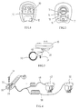
- a conventional, commercially available bicycle cycle computer comprises a main unit 10, and a display 20 for displaying data, such as the speed, the distance traveled, the time and the pedal rpm, is provided on the front surface of the main unit 10.
- a mode button 12 for selecting different displaying modes is provided below the display 20.
- Figure 2 shows the back of the main unit 10.
- reference numeral 13 denotes a battery cap for covering a battery accommodating chamber
- 14 denotes a set button for switching among different data setting modes
- 15 and 16 denote metal contacts for transmitting respective signals representing the detected speed and the detected pedal rpm (which will be described later) to a microprocessor (not shown) installed inside the main unit 10
- 17 denotes a metal contact as a common ground.
- the main unit 10 is preferably made to be detachable from the bicycle and portable.
- a conventional cycle computer is usually equipped with a bracket 30, as shown in Figure 3, which is mounted on a handlebar 90 of a bicycle by means of a screw 31.
- the main unit 10 can be inserted in the direction indicated by the arrow A as shown in Figure 3 so as to be detachably mounted onto the bracket 30.
- the rider can easily remove the main unit 10 from the bracket 30 whenever the bicycle is not in use, and mount the main unit 10 again later.
- Figure 4 shows the connection between the bracket 30 as shown in Figure 3 and two sensors 42 and 52 via cables 46 and 56.
- Figure 5 shows the position relationship between a magnet 44 mounted on one spoke 92 of the front wheel and the sensor 42 of Figure 4 mounted on the inside of the fork 94, facing the magnet 44, and
- Figure 6 shows the position relationship between a magnet 54 mounted on the inside of the crank 95 and the sensor 52 of Figure 4 mounted on the chain stay 96, facing the magnet 54.
- the signals are then transmitted to the microprocessor (not shown) in the main unit 10 through metal contacts 35 and 36 provided on the bracket 30 which are in electrical connection with the contacts 15 and 16 on the back of the main unit 10 when the main unit 10 is mounted on the bracket 30.
- the microprocessor performs, for example, identification, counting and calculation, on the supplied wheel rpm and pedal rpm data, and the processed data are then displayed on the display 20.
- the microprocessor of the main unit 10 calculates the speed by multiplying the wheel rpm with the circumferential length of the front wheel and calculates the distance traveled based on the calculated speed.
- the current pedal rpm or the average pedal rpm can be displayed to facilitate the rider's adjustment.
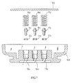
- Waterproof O-rings 15b, 16b and 17b are disposed in the holes 15a, 16a and 17a, respectively.
- Contact pins 15c, 16c and 17c are inserted to pass through the respective O-rings and protrude from the respective holes.
- Springs 15d, 16d and 17d for biasing the respective contact pins 15c, 16c and 17c outwards are provided between the pins and the printed circuit board 102. It is apparent that the waterproof arrangement for the contact is relatively complicated and the manufacturing cost therefore is high.
- a bicycle computer for a bicycle comprising: a first processing unit structured for mounting to the bicycle, a sensor or a plurality of sensors, each sensor providing sensor data to the first processing unit, wherein the first processing unit receives the sensor data from the sensor or the plurality of sensors and outputs serial format data corresponding to the sensor data, a main unit housing including a second processing unit and a display, whereby the second processing receives the serial format data from the first processing unit and outputs display data to the display of a personal computer.
- FIG 8 is a block diagram showing a cycle computer.
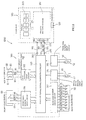
- a cycle computer 1000 comprises a main unit 100 and a bracket 300.
- the main unit 100 is detachably mounted on the bracket 300 as described above in reference to Figure 3.
- the main unit 100 is provided with a primary microprocessor 110 and a display 200 for displaying various data processed by and supplied from the primary microprocessor 110.
- a mode button 120 for selecting different displaying modes is provided on the front surface of the main unit 100.
- Three metal contacts 170, 180 and 190 which are connected to the primary microprocessor 110 via signal transmission lines 171, 181 and 191, respectively, are provided on the back of the main unit 100.
- the contact 170 serves as a ground terminal, while the contact 180 is an input terminal for receiving a synchronous clock signal and the contact 190 is an input terminal for receiving a serial data signal (described in detail later).
- a waterproof arrangement as shown in Figure 7 is provided for each of the contacts 170, 180 and 190.
- the shape of the bracket 300 is substantially the same as that of the conventional bracket 30 as shown in Figures 3 and 4.
- a secondary microprocessor 310 is built in the bracket 300.
- Three metal contacts 370, 380 and 390 are provided on the surface of the bracket 300, and when the main unit 100 is mounted on the bracket 300, the contacts 170, 180 and 190 of the main unit 100 are brought into contact with the contacts 370, 380 and 390 of the bracket 300, respectively.
- the contacts 370, 380 and 390 are connected via signal transmission lines 371, 381 and 391 to three output terminals of a one-way parallel/serial signal converting circuit 320 (described in detail later) in the secondary microprocessor 310.
- the contact 370 serves as a ground terminal for the circuit 320.
- the contact 380 is used as a synchronous clock signal output terminal for the circuit 320 and the contact 390 is a serial data signal output terminal for the circuit 320.
- the secondary microprocessor 310 further comprises a wheel speed sensor input circuit 314, a pedal rpm sensor input circuit 315, a front gear sensor input circuit 316, a rear gear sensor input circuit 317, and a key buttons input circuit 318. Output signals from these circuits 314, 315, 316, 317 and 318 are transmitted to the one-way parallel/serial signal converting circuit 320.
- a wheel speed sensor 42 mounted as shown in Figure 5 is connected to the wheel speed sensor input circuit 314 via two signal transmission lines 46, and a pedal rpm sensor 52 mounted as shown in Figure 6 is connected to the pedal rpm sensor input circuit 315 via two signal transmission lines 56.
- a front gear sensor 60 mounted near one end of the bicycle handlebar is a three-position rotary switch which is connected to the front gear sensor input circuit 316 via three signal transmission lines 66, 67 and 68 and a ground wire 69.
- the front gear sensor 60 is coupled to a front gear shifting device (not shown) in order to detect the front gear in operation and supply the detected signal to the circuit 316.
- a rear gear sensor 70 mounted near the other end of the bicycle handlebar is a nine-position rotary switch which is connected to the rear gear sensor input circuit 317 via nine signal transmission lines 71 to 79 and a ground wire 79'.
- the rear gear sensor 70 is provided to detect the rear gear in operation and supply the detected signal to the circuit 317.
- a key buttons box 80 provided near one end of the handlebar has two remote key buttons 81 and 82.
- the first key button 81 is provided for selecting the displaying mode of the display 200 and the second key button 82 is a start/stop key button for starting or stopping a function of the main unit 100.
- the key buttons box 80 is connected to the key buttons input circuit 318 via two lines 83 and 84 and a ground wire 85.
- the contacts 170, 180 and 190 on the back of the main unit 100 are brought into contact with the contacts 370, 380 and 390 on the bracket 300, respectively, thereby making the primary microprocessor 110 in the main unit 100 and the secondary microprocessor 310 built in the bracket 300 electrically connected.
- a wheel speed signal detected by the wheel speed sensor 42 is transmitted to the wheel speed sensor input circuit 314 via lines 46 and then to the one-way parallel/serial signal converting circuit 320.
- a pedal rpm signal detected by the pedal rpm sensor 52 is supplied to the pedal rpm sensor input circuit 315 via lines 56 and then to the one-way parallel/serial signal converting circuit 320.
- a front gear shifting signal detected by the front gear sensor 60 coupled to the front gear shifting device is transmitted to the front gear sensor input circuit 316 and then to the converting circuit 320.
- a rear gear shifting signal detected by the rear gear sensor 70 coupled to the rear gear shifting device is transmitted to the rear gear sensor input circuit 317 and then to the converting circuit 320.
- a mode selecting signal is transmitted to the key buttons input circuit 318 and then to the converting circuit 320 if the key button 81 of the key buttons box 80 is pressed.
- a start/stop signal is outputted from the key buttons box 80 and transmitted to the key buttons input circuit 318 and then to the converting circuit 320.
- the one-way parallel/serial signal converting circuit 320 receives parallel input signals from the wheel speed sensor 42, the pedal rpm sensor 52, the front gear sensor 60, the rear gear sensor 70 and the key buttons box 80, and then converts the received parallel signals into a serial signal by means of parallel/serial signal conversion.
- the serial signal obtained after the conversion is transmitted from the secondary microprocessor 310 to the primary microprocessor 100 through the serial signal output terminal 390 of the former and the serial signal input terminal 190 of the later.
- the one-way parallel/serial signal converting circuit 320 generates a synchronous clock signal which is transmitted to the primary microprocessor 100 through the synchronous clock signal output terminal 380 and the synchronous clock signal input terminal 180.
- the signals transmitted from the converting circuit 320 of the secondary microprocessor 310 to the primary microprocessor 110 are shown in Figure 9.
- the serial signal comprises a set of data including, for example, BIT1 representing wheel speed data obtained from the wheel speed sensor 42, BIT2 representing pedal rpm data obtained from the pedal rpm sensor 52, BIT3 representing control data transmitted from the key buttons box 80, BIT4 representing front gear data obtained from the front gear sensor 60, BITS representing rear gear data obtained from the rear gear sensor 70, and so on.
- the primary microprocessor 110 performs identification, counting, calculation and other processes on the received data as shown in Figure 9, and displays the processed data requested by the rider on the display 200 of the main unit 100. Two or more kinds of data can be displayed on the display 200 simultaneously.
- the cycle computer comprises more sensors and hence provides more data when compared with the conventional cycle computer without increasing the number of contacts on the back of the main unit. Consequently, the construction of the main unit remains compact and simple.
- the rider can select the displaying mode without moving his hands away from the handlebar.
- a torque sensor is used to detect the torque exerted on the crank shaft and a microprocessor is used to determine whether the detected torque is higher than a predetermined value. If the detected torque is higher than the predetermined value, it indicates that the torque exerted on the crank shaft is too large, and hence a gearing-up is desired in order to reduce the load of the rider. Accordingly, a control signal for gearing-up is outputted from the microprocessor and transmitted to the electronic automatic gear shifting device for performing the gearing-up operation. On the other hand, if the detected torque is lower than the predetermined value, then a gearing-down is desired. Similarly, a control signal for gearing-down is transmitted from the microprocessor to the electronic automatic gear shifting device for performing the gearing-down operation.
- the aforementioned electronic automatic gear shifting device has been practically used, and the microprocessor in such a device can be integrated with the primary microprocessor in the main unit of the cycle computer according to the invention.
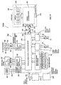
- FIG 10 is a block diagram showing such a cycle computer.
- the cycle computer 1000B comprises a torque sensor 150 for detecting the torque exerted on the crank shaft.
- the detected signal outputted from the torque sensor 150 is transmitted to a torque sensor input circuit 350 via lines 156, and then to a two-way parallel/serial signal converting circuit 330 in the secondary microprocessor 310 built in the bracket 300.
- the signal from the torque sensor 150 is converted together with signals from other sensors (42, 52, 60, 70) into a serial signal which is transmitted from the two-way parallel/serial signal converting circuit 330 to the primary microprocessor 110 in the main unit 100 through the serial signal output terminal 390.
- the primary microprocessor 110 determines whether the torque exerted on the crank shaft is higher or lower than a predetermined value based on the signal obtained from the torque sensor 150. If it is determined that the torque is higher than the predetermined value, then the torque exerted on the crank shaft is too large, and hence a gearing-up is desired. Accordingly, a control signal is outputted from the primary microprocessor 110 and transmitted to the secondary microprocessor 310 which then outputs a control signal OP for gearing-up to a gear shifting mechanism 450 of an electronic automatic gear shifting device 400 for performing the gearing-up operation through signal transmission lines 336 and 456. On the other hand, if the torque is lower than the predetermined value, it indicates that a gearing-down is desired. Therefore, the primary microprocessor 110 outputs a control signal for gearing-down which is then transmitted to the gear shifting mechanism 450 of the electronic automatic gear shifting device 400 for performing the gearing-down operation.
- control signals for gearing-up and gearing-down outputted from the primary microprocessor 110 are transmitted to the secondary microprocessor 310 via the existing lines 191 and 391 and the metal contacts 190 and 390.
- the cycle computer 1000B according to the invention can share the same microprocessor with an existing electronic automatic gear shifting device, thereby increasing the function of the cycle computer.
- sensors for detecting the physiological conditions of the rider and sensors for detecting the ambient conditions such as the temperature and the pressure are not incorporated therein, the addition of these sensors and other sensors becomes apparent for those skilled in the same field in the light of the teaching disclosed above.
Description
- The present invention relates to a bicycle cycle computer for displaying various kinds of information regarding the speed, the pedal revolution per minute (rpm), the gear in operation, the pulse of the rider, the ambient temperature, the geographical height and the like.
- Generally speaking, since a bicycle cycle computer is mounted on a bicycle and mainly used outdoors, it is required to be not only compact but also waterproof, shockproof and weatherproof. As shown in Figure 1, a conventional, commercially available bicycle cycle computer comprises a
main unit 10, and adisplay 20 for displaying data, such as the speed, the distance traveled, the time and the pedal rpm, is provided on the front surface of themain unit 10. Amode button 12 for selecting different displaying modes is provided below thedisplay 20. Figure 2 shows the back of themain unit 10. In Figure 2,reference numeral 13 denotes a battery cap for covering a battery accommodating chamber, 14 denotes a set button for switching among different data setting modes, 15 and 16 denote metal contacts for transmitting respective signals representing the detected speed and the detected pedal rpm (which will be described later) to a microprocessor (not shown) installed inside themain unit - In addition, in order to prevent the
main unit 10 from being stolen, themain unit 10 is preferably made to be detachable from the bicycle and portable. For this purpose, a conventional cycle computer is usually equipped with abracket 30, as shown in Figure 3, which is mounted on ahandlebar 90 of a bicycle by means of ascrew 31. Themain unit 10 can be inserted in the direction indicated by the arrow A as shown in Figure 3 so as to be detachably mounted onto thebracket 30. Thus, the rider can easily remove themain unit 10 from thebracket 30 whenever the bicycle is not in use, and mount themain unit 10 again later. - Figure 4 shows the connection between the
bracket 30 as shown in Figure 3 and twosensors cables sensor 42 of Figure 4 mounted on the inside of thefork 94, facing the magnet 44, and Figure 6 shows the position relationship between amagnet 54 mounted on the inside of thecrank 95 and thesensor 52 of Figure 4 mounted on thechain stay 96, facing themagnet 54. - Among various data which can be displayed on the
display 20 of themain unit 10, except the time data which is provided by a clock circuit built in themain unit 10, all the other data including the speed, the distance, the pedal rpm, etc., are obtained from signals supplied by thesensors fork 94 and thechain stay 96, respectively. Thesensors pedal crank 95 by sensing theassociated magnets 44 and 54. Thesensors cables bracket 30. The signals are then transmitted to the microprocessor (not shown) in themain unit 10 throughmetal contacts bracket 30 which are in electrical connection with thecontacts main unit 10 when themain unit 10 is mounted on thebracket 30. The microprocessor performs, for example, identification, counting and calculation, on the supplied wheel rpm and pedal rpm data, and the processed data are then displayed on thedisplay 20. - For example, the microprocessor of the
main unit 10 calculates the speed by multiplying the wheel rpm with the circumferential length of the front wheel and calculates the distance traveled based on the calculated speed. In addition, the current pedal rpm or the average pedal rpm can be displayed to facilitate the rider's adjustment. - Therefore, as far as the
main unit 10 of a cycle computer having twosensors contacts main unit 10 and acontact 17 for a common ground. That is, it is necessary to provide at least three contacts on the back of the main unit. Each of thesecontacts main unit 10 with a waterproof arrangement in order to prevent water from leaking into the interior of themain unit 10 to thereby result in a short circuit phenomenon. A typical waterproof arrangement for the contact is shown in Figure 7.Holes 15a, 16a and 17a are provided at the bottom of a lower case 10a of themain unit 10. Waterproof O-rings holes 15a, 16a and 17a, respectively. Contactpins respective contact pins circuit board 102. It is apparent that the waterproof arrangement for the contact is relatively complicated and the manufacturing cost therefore is high. - Recently, following the development of the handlebar-type gear shifting device and the electronic gear shifting device, there is a demand for a new generation cycle computer which in addition to display the aforementioned data concerning the speed, the distance, the time and the pedal rpm, is also capable of displaying data concerning the gear in operation, the torque exerted on the crank shaft, the ambient temperature, the geographical height and even the pulse of the rider. This means a significant increase in the number of the sensors and hence the metal contacts on the back of the main unit and the corresponding metal contacts on the bracket. Due to the significantly increased number of the metal contacts, it is difficult to keep the main unit compact. In addition, it is necessary to provide a waterproof arrangement for each of the contacts, thereby resulting in a very complicated structure and an increased manufacturing cost.
- Furthermore from DE-U-2 96 04 853 a bicycle computer for a bicycle is known, comprising: a first processing unit structured for mounting to the bicycle, a sensor or a plurality of sensors, each sensor providing sensor data to the first processing unit, wherein the first processing unit receives the sensor data from the sensor or the plurality of sensors and outputs serial format data corresponding to the sensor data, a main unit housing including a second processing unit and a display, whereby the second processing receives the serial format data from the first processing unit and outputs display data to the display of a personal computer.
- These above mentioned features are forming the preamble of
claim 1 of the application. This known bicycle computer is also not suitable for solving all the before mentioned demands. - Documents DE 34 45 617 A1 and JP-58 132 807 refer to the conversion of parallel sensor data into serial data. Also these documents cannot contribute to simplificate the known bicycle computers.
- Document US-5 261 858 refers to a system for computer controlled shifting of a bicycle. This document discloses a bicycle computer without any separate main unit housing or mounting bracket for mounting the computer to the bicycle. Thus this document is also not suitable for a further development of the known bicycle computers to solve the before mentioned demands.
- In view of the aforementioned problem, it is therefore an object of the invention to provide a bicycle cycle computer which is capable of displaying more kinds of information when compared with conventional cycle computers without increasing the number of contacts on the main unit thereof.
- In order to achieve the above object, according to the invention, there is provided a bicycle cycle computer according to the characterizing features of
claim 1. Advantageous embodiments of the invention are forming the characterizing features of the dependent claims. -
- Figure 1 is a front view showing a main unit of a conventional bicycle cycle computer;
- Figure 2 is rear view showing the main unit of the conventional cycle computer of Figure 1;
- Figure 3 is a side view showing the state of the main unit of Figure 1 mounted on a bracket;
- Figure 4 is a perspective view showing the connection between the bracket of Figure 3 and two sensors;
- Figure 5 is a side view showing the mounting manner of a wheel speed sensor and a wheel magnet;
- Figure 6 is a perspective view showing the mounting manner of a pedal rpm sensor and a pedal magnet;
- Figure 7 is a sectional view showing water-scaled arrangements for metal contacts of the main unit;
- Figure 8 is a block diagram showing a bicycle cycle computer;
- Figure 9 is a wave form diagram showing a serial data signal and a synchronous clock signal;
- Figure 10 is a block diagram showing a cycle computer according to the invention.
-
- Figure 8 is a block diagram showing a cycle computer. As shown in Figure 8, a
cycle computer 1000 comprises amain unit 100 and abracket 300. Themain unit 100 is detachably mounted on thebracket 300 as described above in reference to Figure 3. Similar to the conventionalmain unit 10 shown in Figures 1 and 2, themain unit 100 is provided with aprimary microprocessor 110 and adisplay 200 for displaying various data processed by and supplied from theprimary microprocessor 110. In addition, amode button 120 for selecting different displaying modes is provided on the front surface of themain unit 100. Threemetal contacts primary microprocessor 110 viasignal transmission lines main unit 100. Thecontact 170 serves as a ground terminal, while thecontact 180 is an input terminal for receiving a synchronous clock signal and thecontact 190 is an input terminal for receiving a serial data signal (described in detail later). A waterproof arrangement as shown in Figure 7 is provided for each of thecontacts - The shape of the
bracket 300 is substantially the same as that of theconventional bracket 30 as shown in Figures 3 and 4. However, according to the invention, asecondary microprocessor 310 is built in thebracket 300. Threemetal contacts bracket 300, and when themain unit 100 is mounted on thebracket 300, thecontacts main unit 100 are brought into contact with thecontacts bracket 300, respectively. Thecontacts signal transmission lines secondary microprocessor 310. The contact 370 serves as a ground terminal for thecircuit 320. Thecontact 380 is used as a synchronous clock signal output terminal for thecircuit 320 and thecontact 390 is a serial data signal output terminal for thecircuit 320. - As shown in Figure 8, in addition to the one-way parallel/serial
signal converting circuit 320, thesecondary microprocessor 310 further comprises a wheel speedsensor input circuit 314, a pedal rpmsensor input circuit 315, a front gearsensor input circuit 316, a rear gearsensor input circuit 317, and a keybuttons input circuit 318. Output signals from thesecircuits signal converting circuit 320. - A
wheel speed sensor 42 mounted as shown in Figure 5 is connected to the wheel speedsensor input circuit 314 via twosignal transmission lines 46, and apedal rpm sensor 52 mounted as shown in Figure 6 is connected to the pedal rpmsensor input circuit 315 via twosignal transmission lines 56. - A
front gear sensor 60 mounted near one end of the bicycle handlebar is a three-position rotary switch which is connected to the front gearsensor input circuit 316 via threesignal transmission lines ground wire 69. Thefront gear sensor 60 is coupled to a front gear shifting device (not shown) in order to detect the front gear in operation and supply the detected signal to thecircuit 316. - A
rear gear sensor 70 mounted near the other end of the bicycle handlebar is a nine-position rotary switch which is connected to the rear gearsensor input circuit 317 via ninesignal transmission lines 71 to 79 and a ground wire 79'. Therear gear sensor 70 is provided to detect the rear gear in operation and supply the detected signal to thecircuit 317. - A
key buttons box 80 provided near one end of the handlebar has two remotekey buttons key button 81 is provided for selecting the displaying mode of thedisplay 200 and the secondkey button 82 is a start/stop key button for starting or stopping a function of themain unit 100. Thekey buttons box 80 is connected to the keybuttons input circuit 318 via twolines ground wire 85. - Next, the operation of the cycle computer comprising the above components will be described in the following.
- When the
main unit 100 is mounted on thebracket 300, thecontacts main unit 100 are brought into contact with thecontacts bracket 300, respectively, thereby making theprimary microprocessor 110 in themain unit 100 and thesecondary microprocessor 310 built in thebracket 300 electrically connected. - When a rider is riding a bicycle equipped with the cycle computer according to the invention described above, a wheel speed signal detected by the
wheel speed sensor 42 is transmitted to the wheel speedsensor input circuit 314 vialines 46 and then to the one-way parallel/serialsignal converting circuit 320. Similarly, a pedal rpm signal detected by thepedal rpm sensor 52 is supplied to the pedal rpmsensor input circuit 315 vialines 56 and then to the one-way parallel/serialsignal converting circuit 320. - In addition, a front gear shifting signal detected by the
front gear sensor 60 coupled to the front gear shifting device is transmitted to the front gearsensor input circuit 316 and then to the convertingcircuit 320. Likewise, a rear gear shifting signal detected by therear gear sensor 70 coupled to the rear gear shifting device is transmitted to the rear gearsensor input circuit 317 and then to the convertingcircuit 320. - A mode selecting signal is transmitted to the key
buttons input circuit 318 and then to the convertingcircuit 320 if thekey button 81 of thekey buttons box 80 is pressed. On the other hand, if thekey button 82 is pressed, a start/stop signal is outputted from thekey buttons box 80 and transmitted to the keybuttons input circuit 318 and then to the convertingcircuit 320. - Therefore, the one-way parallel/serial
signal converting circuit 320 receives parallel input signals from thewheel speed sensor 42, thepedal rpm sensor 52, thefront gear sensor 60, therear gear sensor 70 and thekey buttons box 80, and then converts the received parallel signals into a serial signal by means of parallel/serial signal conversion. The serial signal obtained after the conversion is transmitted from thesecondary microprocessor 310 to theprimary microprocessor 100 through the serialsignal output terminal 390 of the former and the serialsignal input terminal 190 of the later. At the same time, the one-way parallel/serialsignal converting circuit 320 generates a synchronous clock signal which is transmitted to theprimary microprocessor 100 through the synchronous clocksignal output terminal 380 and the synchronous clocksignal input terminal 180. - The signals transmitted from the converting
circuit 320 of thesecondary microprocessor 310 to theprimary microprocessor 110 are shown in Figure 9. The serial signal comprises a set of data including, for example, BIT1 representing wheel speed data obtained from thewheel speed sensor 42, BIT2 representing pedal rpm data obtained from thepedal rpm sensor 52, BIT3 representing control data transmitted from thekey buttons box 80, BIT4 representing front gear data obtained from thefront gear sensor 60, BITS representing rear gear data obtained from therear gear sensor 70, and so on. - The
primary microprocessor 110 performs identification, counting, calculation and other processes on the received data as shown in Figure 9, and displays the processed data requested by the rider on thedisplay 200 of themain unit 100. Two or more kinds of data can be displayed on thedisplay 200 simultaneously. - Since the signals supplied from the
sensors key buttons box 80 are converted into a serial signal as shown in Figure 9 by the one-way parallel/serialsignal converting circuit 320 in thesecondary microprocessor 310 built in thebracket 300 before transmitted to theprimary microprocessor 110 in themain unit 100, only three pairs of contacts are needed for the electrical connection between thebracket 300 and themain unit 100, that is, the pair ofcontacts contacts contacts 370 and 170 for the ground wire. In other words, themain unit 100 is provided with only threecontacts - In addition, with the separated key buttons box provided near the handlebar of the bicycle and connected to the secondary microprocessor, the rider can select the displaying mode without moving his hands away from the handlebar.
- Recently, electronic automatic gear shifting devices have been developed. In such a device, a torque sensor is used to detect the torque exerted on the crank shaft and a microprocessor is used to determine whether the detected torque is higher than a predetermined value. If the detected torque is higher than the predetermined value, it indicates that the torque exerted on the crank shaft is too large, and hence a gearing-up is desired in order to reduce the load of the rider. Accordingly, a control signal for gearing-up is outputted from the microprocessor and transmitted to the electronic automatic gear shifting device for performing the gearing-up operation. On the other hand, if the detected torque is lower than the predetermined value, then a gearing-down is desired. Similarly, a control signal for gearing-down is transmitted from the microprocessor to the electronic automatic gear shifting device for performing the gearing-down operation.
- The aforementioned electronic automatic gear shifting device has been practically used, and the microprocessor in such a device can be integrated with the primary microprocessor in the main unit of the cycle computer according to the invention.
- Figure 10 is a block diagram showing such a cycle computer. In addition to the sensors described in figure 8, as shown in Figure 10, the cycle computer 1000B comprises a
torque sensor 150 for detecting the torque exerted on the crank shaft. The detected signal outputted from thetorque sensor 150 is transmitted to a torquesensor input circuit 350 vialines 156, and then to a two-way parallel/serialsignal converting circuit 330 in thesecondary microprocessor 310 built in thebracket 300. The signal from thetorque sensor 150 is converted together with signals from other sensors (42, 52, 60, 70) into a serial signal which is transmitted from the two-way parallel/serialsignal converting circuit 330 to theprimary microprocessor 110 in themain unit 100 through the serialsignal output terminal 390. Theprimary microprocessor 110 determines whether the torque exerted on the crank shaft is higher or lower than a predetermined value based on the signal obtained from thetorque sensor 150. If it is determined that the torque is higher than the predetermined value, then the torque exerted on the crank shaft is too large, and hence a gearing-up is desired. Accordingly, a control signal is outputted from theprimary microprocessor 110 and transmitted to thesecondary microprocessor 310 which then outputs a control signal OP for gearing-up to agear shifting mechanism 450 of an electronic automaticgear shifting device 400 for performing the gearing-up operation throughsignal transmission lines 336 and 456. On the other hand, if the torque is lower than the predetermined value, it indicates that a gearing-down is desired. Therefore, theprimary microprocessor 110 outputs a control signal for gearing-down which is then transmitted to thegear shifting mechanism 450 of the electronic automaticgear shifting device 400 for performing the gearing-down operation. - In this case, the control signals for gearing-up and gearing-down outputted from the
primary microprocessor 110 are transmitted to thesecondary microprocessor 310 via the existinglines metal contacts - The cycle computer 1000B according to the invention can share the same microprocessor with an existing electronic automatic gear shifting device, thereby increasing the function of the cycle computer.
- Although in the embodiments described above, sensors for detecting the physiological conditions of the rider and sensors for detecting the ambient conditions such as the temperature and the pressure are not incorporated therein, the addition of these sensors and other sensors becomes apparent for those skilled in the same field in the light of the teaching disclosed above.
- While the present invention has been described above in detail in connection with its preferred embodiments, it is to be understood that the present invention is not limited to the details of the illustrated embodiments, but may have various changes, modifications and improvements, which may occur to those skilled in the art, without departing from the wording of the claims.
Claims (9)
- A bicycle computer for a bicycle comprising:wherein the first processing unit (310) receives the sensor data from the sensor or the plurality of sensors (42, 52, 60, 70) and outputs serial format data corresponding to the sensor data,a first processing unit (310) structured for mounting to the bicycle,a sensor or a plurality of sensors (42, 52, 60, 70, 80), each sensor providing sensor data to the first processing unit (310),
a main unit housing including a second processing unit (110) and a display (200), whereby
the second processing unit (110) receives the serial format data from the first processing unit (310) and outputs display data to the display (200),
characterized in that
each sensor or the plurality of sensors (42, 52, 60, 70, 80) provides sensor data in parallel format to the first processing unit (310),
the main unit housing is detachably mountable to the bicycle and
the main unit (100) is connected over signal transmission lines to the first processing unit,
the first processing unit (310) and the main unit (100) each having contacts for connection to said transmission lines,
wherein the first processing unit (310) includes a command output terminal (336) for controlling a gear shift mechanism. - A bicycle computer according to claim 1, wherein the first processing unit (310) communicates the serial format data to the second processing unit (110) via a first contact provided on the main unit housing.
- A bicycle computer according to claim 1 or 2, wherein only a single first contact communicates the serial format data from the first processing unit (310) to the second processing unit (110).
- A bicycle computer according to any of the preceding claims, wherein the second processing unit (110) communicates control information for outputting the control command via the first contact to the first processing unit (310).
- A bicycle computer according to any of the preceding claims, wherein the first processing unit (310) generates a synchronous clock signal which is communicated to the second processing unit (110) via a second contact provided on the main unit housing.
- A bicycle computer according to claim 5, wherein only a single second contact communicates the clock signal form the first processing unit (310) to the second processing unit (110).
- A bicycle computer according to any of the preceding claims, wherein a third contact is provided on the main unit housing for communicating a ground signal from the first processing unit (310) to the second processing unit (110).
- A bicycle computer according to any of the preceding claims, wherein the first processing unit (310) is arranged for connection with sensors which include a wheel speed sensor or/and a pedal rpm sensor or/and a front gear sensor or/and a rear gear sensor or/and a least a sensor which is attached to a rider's body for detecting various physiological conditions of the rider.
- A bicycle computer for a bicycle according to any of the preceding claims, wherein exactly three communication paths communicate signals from the first processing unit (310) to the second processing unit (110).
Applications Claiming Priority (2)
| Application Number | Priority Date | Filing Date | Title |
|---|---|---|---|
| US08/896,309 US6192300B1 (en) | 1997-06-27 | 1997-06-27 | Bicycle computer |
| US896309 | 1997-06-27 |
Publications (2)
| Publication Number | Publication Date |
|---|---|
| EP0887251A1 EP0887251A1 (en) | 1998-12-30 |
| EP0887251B1 true EP0887251B1 (en) | 2003-02-12 |
Family
ID=25405988
Family Applications (1)
| Application Number | Title | Priority Date | Filing Date |
|---|---|---|---|
| EP98111009A Expired - Lifetime EP0887251B1 (en) | 1997-06-27 | 1998-06-16 | Bicycle computer |
Country Status (7)
| Country | Link |
|---|---|
| US (1) | US6192300B1 (en) |
| EP (1) | EP0887251B1 (en) |
| CN (1) | CN1086807C (en) |
| CZ (1) | CZ297059B6 (en) |
| DE (1) | DE69811295T2 (en) |
| PL (1) | PL188812B1 (en) |
| SK (1) | SK86698A3 (en) |
Families Citing this family (50)
| Publication number | Priority date | Publication date | Assignee | Title |
|---|---|---|---|---|
| IT1310144B1 (en) * | 1999-08-24 | 2002-02-11 | Ferrero Spa | SYSTEM AND PROCEDURE FOR THE CONTROL OF TRANSMISSIONS WITH VARIABLE RATIO |
| US6543799B2 (en) | 2000-01-13 | 2003-04-08 | Shimano Inc. | Bicycle suspension |
| IT1320286B1 (en) * | 2000-03-29 | 2003-11-26 | Campagnolo Srl | MULTIPROCESSOR CONTROL SYSTEM FOR CYCLES, FOR EXAMPLE COMPETITION BICYCLES. |
| IT1320285B1 (en) | 2000-03-29 | 2003-11-26 | Campagnolo Srl | PROCEDURE FOR CHECKING THE SPEED CHANGE IN A CYCLE, ITS SYSTEM AND ITS COMPONENTS. |
| IT1320289B1 (en) | 2000-03-29 | 2003-11-26 | Campagnolo Srl | SYSTEM FOR THE TRANSFER OF DATA, FOR EXAMPLE FOR QUALIFYING CYCLES FOR COMPETITION. |
| US6836711B2 (en) | 2002-04-05 | 2004-12-28 | Michael Leonard Gentilcore | Bicycle data acquisition |
| US7015598B2 (en) * | 2002-04-23 | 2006-03-21 | Shimano, Inc. | Power control apparatus for a bicycle |
| US6741045B2 (en) * | 2002-04-23 | 2004-05-25 | Shimano, Inc. | Bicycle control apparatus that communicates power and data over a single transmission path |
| US7116008B2 (en) * | 2002-04-23 | 2006-10-03 | Shimano, Inc. | Electrical communication system for a bicycle |
| JP3635306B2 (en) * | 2002-06-11 | 2005-04-06 | 株式会社キャットアイ | Handle stem and speed indicator |
| US6724299B2 (en) * | 2002-06-27 | 2004-04-20 | Shimano, Inc. | Bicycle data communication method and apparatus |
| US6781510B2 (en) * | 2002-07-24 | 2004-08-24 | Shimano, Inc. | Bicycle computer control arrangement and method |
| JP2004110628A (en) | 2002-09-20 | 2004-04-08 | Shimano Inc | Bicycle user's information management device and cycle computer |
| US7006901B2 (en) * | 2002-11-18 | 2006-02-28 | Wang Everett X | Computerized automated dynamic control system for single-track vehicles |
| JP2004256047A (en) * | 2003-02-27 | 2004-09-16 | Shimano Inc | Distance display system for bicycle and its device |
| JP3717076B2 (en) * | 2003-03-11 | 2005-11-16 | 株式会社シマノ | Shift control device for motorcycle |
| JP3777360B2 (en) * | 2003-03-27 | 2006-05-24 | 株式会社シマノ | Bicycle information processing device |
| JP3953990B2 (en) * | 2003-08-22 | 2007-08-08 | 株式会社キャットアイ | Measuring device and sensor device |
| JP2005104258A (en) * | 2003-09-30 | 2005-04-21 | Shimano Inc | Electrical instrument holder for bicycle |
| US7612759B2 (en) * | 2004-05-12 | 2009-11-03 | Shimano Inc. | Cycle computer display apparatus |
| DE102004041832B3 (en) * | 2004-08-27 | 2005-12-08 | Cycle Parts Gmbh | Magnetic pulse generator |
| US7740115B2 (en) * | 2004-11-24 | 2010-06-22 | Shimano Inc. | Bicycle sensor unit |
| DE102005039615B4 (en) * | 2005-08-19 | 2007-05-03 | Sigma-Elektro Gmbh | Device for adjusting the wheel size of a bicycle on a bicycle computer |
| DE602005021896D1 (en) * | 2005-12-02 | 2010-07-29 | Campagnolo Srl | Crankset for the bottom bracket, the drive shaft and the pedal crank of a bicycle |
| EP1820726B1 (en) * | 2006-02-20 | 2011-09-14 | Campagnolo S.r.l. | Bicycle bottom bracket assembly |
| ATE495090T1 (en) * | 2006-03-03 | 2011-01-15 | Campagnolo Srl | BICYCLE CRANK BEARING ARRANGEMENT AND AN ADAPTER FOR SUCH ARRANGEMENT |
| CA2647839A1 (en) * | 2006-03-31 | 2007-10-11 | 1531073 Ontario Inc. | Bicycle head tube mount for electronic peripheral devices |
| JP2007297040A (en) | 2006-05-04 | 2007-11-15 | Campagnolo Spa | Crank arm assembly for bicycle |
| ITMI20070140A1 (en) * | 2007-01-30 | 2008-07-31 | Campagnolo Srl | MAN-BICYCLE INTERACTION DEVICE |
| ITMI20070737A1 (en) * | 2007-04-12 | 2008-10-13 | Campagnolo Srl | EQUIPMENT AND ELECTRONIC SYSTEM FOR BICYCLE AND RELATIVE METHODS |
| US7878521B2 (en) * | 2007-04-16 | 2011-02-01 | Trek Bicycle Corporation | Bicycle frame with device cavity |
| US20090088934A1 (en) * | 2007-09-28 | 2009-04-02 | Shimano Inc. | Bicycle control system |
| US7902967B2 (en) * | 2007-10-23 | 2011-03-08 | Shimano Inc. | Bicycle control system |
| ITMI20070406U1 (en) * | 2007-12-05 | 2009-06-06 | Campagnolo Srl | ASSEMBLY OF CENTRAL MOVEMENT OF BICYCLE AND TREE FOR A SUCH ASSEMBLY |
| ITMI20072407A1 (en) * | 2007-12-20 | 2009-06-21 | Campagnolo Srl | ELECTRONIC EQUIPMENT FOR BICYCLE |
| JP5046909B2 (en) * | 2007-12-21 | 2012-10-10 | 株式会社日本マイクロニクス | Contact for electrical test, electrical connection device using the contact, and method for manufacturing contact |
| EP2757030B1 (en) * | 2008-01-24 | 2015-12-23 | Cycling Sports Group, Inc. | Bicycle user interface system and method of operation thereof |
| US20100010709A1 (en) * | 2008-01-24 | 2010-01-14 | Cannondale Bicycle Corporation | Bicycle distributed computing arrangement and method of operation |
| US8213794B2 (en) * | 2008-02-12 | 2012-07-03 | Nec Laboratories America, Inc. | Programmable optical network architecture |
| US7761212B2 (en) * | 2008-03-24 | 2010-07-20 | Shimano Inc. | Wireless communication apparatus |
| EP2110301B1 (en) * | 2008-04-17 | 2014-12-24 | CAMPAGNOLO S.r.l. | Assembly of bicycle components in mutual rotation and bicycle comprising such an assembly |
| US8643722B2 (en) * | 2008-10-08 | 2014-02-04 | Cerevellum Design, Llc | Rear-view display system for a bicycle |
| US20100123402A1 (en) * | 2008-11-19 | 2010-05-20 | Yi-Lun Chen | Bicycle control device |
| AR076221A1 (en) * | 2009-04-09 | 2011-05-26 | Astrazeneca Ab | DERIVED FROM PIRAZOL [4,5-E] PYRIMIDINE AND ITS USE TO TREAT DIABETES AND OBESITY |
| FI20095888A0 (en) * | 2009-08-28 | 2009-08-28 | Polar Electro Oy | The cycling computer |
| US9702937B2 (en) * | 2015-02-17 | 2017-07-11 | Lg Chem, Ltd. | Contactor control system |
| CN105015664A (en) * | 2015-07-30 | 2015-11-04 | 徐开友 | Touch display screen bicycle speed meter and manufacturing method thereof |
| CN105903154A (en) * | 2016-05-16 | 2016-08-31 | 胡亚洲 | Active bodybuilding bicycle |
| CN107438768B (en) * | 2016-09-30 | 2020-05-19 | 深圳博芯科技股份有限公司 | 2.4GHz wireless code meter circuit |
| JP1619067S (en) * | 2017-11-13 | 2018-11-26 |
Family Cites Families (26)
| Publication number | Priority date | Publication date | Assignee | Title |
|---|---|---|---|---|
| FR2308910A1 (en) * | 1975-04-21 | 1976-11-19 | Genzling Claude | INTEGRATED COUNTER-TACHOMETER DEVICE FOR BICYCLES |
| JPS58132807A (en) * | 1982-01-30 | 1983-08-08 | Hino Motors Ltd | Control data display for car engine controller |
| JPS5992812A (en) | 1982-11-13 | 1984-05-29 | Masaki Date | Material feeding device of press machine |
| JPS60118711U (en) * | 1984-01-20 | 1985-08-10 | 株式会社キャットアイ | Bicycle riding data display device |
| DE3445617A1 (en) | 1984-07-13 | 1985-07-04 | Max Stegmann GmbH, Uhren- und Elektroapparatefabrik, 7710 Donaueschingen | Method and arrangement for the serial transmission of the digital measurement values of a measurement transducer |
| JPS62237895A (en) | 1986-04-09 | 1987-10-17 | Nippon Denso Co Ltd | On-vihicle communication equipment |
| US4828257A (en) * | 1986-05-20 | 1989-05-09 | Powercise International Corporation | Electronically controlled exercise system |
| US5059158A (en) * | 1990-05-08 | 1991-10-22 | E.B.T., Inc. | Electronic transmission control system for a bicycle |
| JPH04104088A (en) | 1990-08-23 | 1992-04-06 | Toshiba Corp | Apparatus for shutting down nuclear reactor |
| US5177432A (en) * | 1991-05-31 | 1993-01-05 | Ppg Industries, Inc. | Wireless velocity detector for a bicycle having a rotating AC magnetic field and receiver coils |
| JPH0516041A (en) | 1991-07-08 | 1993-01-26 | Sekisui Chem Co Ltd | Work instruction system in assembly line |
| DE4212319A1 (en) | 1992-04-13 | 1993-10-14 | Fichtel & Sachs Ag | control device |
| DE4212320A1 (en) | 1992-04-13 | 1993-10-14 | Fichtel & Sachs Ag | Electric actuator |
| US5261858A (en) | 1992-06-19 | 1993-11-16 | Browning Automatic Transmission | Method and system for computer-controlled bicycle gear shifting |
| JPH0635573A (en) | 1992-07-20 | 1994-02-10 | Citizen Watch Co Ltd | Power circuit device |
| JPH06203287A (en) | 1992-12-30 | 1994-07-22 | Casio Comput Co Ltd | Radio type measuring instrument |
| JPH06317601A (en) | 1993-04-30 | 1994-11-15 | Sanyo Electric Co Ltd | Speedometer for bicycle |
| JPH0717461A (en) | 1993-06-30 | 1995-01-20 | Casio Comput Co Ltd | Optimum momentum setting device |
| JP3475458B2 (en) | 1993-09-28 | 2003-12-08 | カシオ計算機株式会社 | Running state detecting device and running state detecting receiver |
| JPH07282905A (en) | 1994-04-04 | 1995-10-27 | Casio Comput Co Ltd | Electronic equipment provided with external connection terminal and connection structure thereof |
| JP2629609B2 (en) | 1994-08-23 | 1997-07-09 | 株式会社デンソー | Control system data output method |
| JPH08133165A (en) | 1994-11-09 | 1996-05-28 | Yamaha Motor Co Ltd | Abnormality supervising device for motor assisted bicycle |
| US5644511A (en) * | 1995-04-26 | 1997-07-01 | Mcwhorter; Gary T. | Cyclometer computer |
| DE29604853U1 (en) | 1996-03-15 | 1996-05-23 | Poellmann Norbert | Device for recording tours |
| US5737247A (en) * | 1996-04-04 | 1998-04-07 | Phil Orbanes Productions, Inc. | Bicycle accessory with voice synthesis capability |
| JP3088661B2 (en) | 1996-07-23 | 2000-09-18 | 株式会社シマノ | Method and apparatus for transmitting detection signal in bicycle |
-
1997
- 1997-06-27 US US08/896,309 patent/US6192300B1/en not_active Expired - Lifetime
-
1998
- 1998-06-16 EP EP98111009A patent/EP0887251B1/en not_active Expired - Lifetime
- 1998-06-16 DE DE69811295T patent/DE69811295T2/en not_active Expired - Lifetime
- 1998-06-19 SK SK866-98A patent/SK86698A3/en unknown
- 1998-06-24 CZ CZ0201598A patent/CZ297059B6/en not_active IP Right Cessation
- 1998-06-25 PL PL98327025A patent/PL188812B1/en not_active IP Right Cessation
- 1998-06-26 CN CN98115508A patent/CN1086807C/en not_active Expired - Fee Related
Also Published As
| Publication number | Publication date |
|---|---|
| SK86698A3 (en) | 2000-02-14 |
| CZ9802015A3 (en) | 1999-01-13 |
| EP0887251A1 (en) | 1998-12-30 |
| CZ297059B6 (en) | 2006-08-16 |
| PL327025A1 (en) | 1999-01-04 |
| DE69811295T2 (en) | 2003-09-11 |
| PL188812B1 (en) | 2005-04-29 |
| US6192300B1 (en) | 2001-02-20 |
| CN1086807C (en) | 2002-06-26 |
| CN1212361A (en) | 1999-03-31 |
| DE69811295D1 (en) | 2003-03-20 |
Similar Documents
| Publication | Publication Date | Title |
|---|---|---|
| EP0887251B1 (en) | Bicycle computer | |
| US6204752B1 (en) | Bicycle display unit with backlight | |
| EP1693292B1 (en) | Bicycle control apparatus | |
| US7253610B2 (en) | Self-powered bicycle signal output device and display apparatus using same | |
| EP1693290A2 (en) | Apparatus for mounting an electrical component to a bicycle | |
| EP1357678B1 (en) | Bicycle control apparatus that communicates power and data over a single transmission path | |
| JP3231018B2 (en) | Bicycle computer | |
| CN101417689A (en) | Bicycle control system | |
| EP3828071A1 (en) | Interface for electric assist bicycle | |
| EP1693291A2 (en) | Water resisting apparatus for a bicycle electrical component | |
| US6084506A (en) | Display apparatus for a bicycle | |
| US20070270719A1 (en) | Automatic speed setting system for bicycle use | |
| EP1520777B1 (en) | Electronic control device for bicycle | |
| EP1693289B1 (en) | Electrical connector apparatus for a bicycle | |
| RU2253896C2 (en) | Bicycle computer (variants) | |
| CN209870655U (en) | Bicycle brake handle | |
| NZ333459A (en) | Electronic module for conventional parking meter | |
| CN217496432U (en) | Electric scooter control system | |
| CN215682297U (en) | Wireless image transmission frequency matching device | |
| EP1594723A2 (en) | Combination switch module | |
| CN216388434U (en) | Driving simulator and in-loop hardware testing system | |
| TW201836912A (en) | Bicycle drive system, bicycle drive unit, and bicycle battery unit | |
| CN115123436A (en) | Electric scooter control system | |
| CA2545891A1 (en) | Automatic speed setting system for bicycle use | |
| GB2439090A (en) | Bicycle with automatic speed setting in response to physiological parameters |
Legal Events
| Date | Code | Title | Description |
|---|---|---|---|
| PUAI | Public reference made under article 153(3) epc to a published international application that has entered the european phase |
Free format text: ORIGINAL CODE: 0009012 |
|
| AK | Designated contracting states |
Kind code of ref document: A1 Designated state(s): DE FR IT |
|
| AX | Request for extension of the european patent |
Free format text: AL;LT;LV;MK;RO;SI |
|
| 17P | Request for examination filed |
Effective date: 19990125 |
|
| AKX | Designation fees paid |
Free format text: DE FR IT |
|
| 17Q | First examination report despatched |
Effective date: 19990927 |
|
| GRAH | Despatch of communication of intention to grant a patent |
Free format text: ORIGINAL CODE: EPIDOS IGRA |
|
| GRAH | Despatch of communication of intention to grant a patent |
Free format text: ORIGINAL CODE: EPIDOS IGRA |
|
| GRAA | (expected) grant |
Free format text: ORIGINAL CODE: 0009210 |
|
| AK | Designated contracting states |
Designated state(s): DE FR IT |
|
| REF | Corresponds to: |
Ref document number: 69811295 Country of ref document: DE Date of ref document: 20030320 Kind code of ref document: P |
|
| RAP2 | Party data changed (patent owner data changed or rights of a patent transferred) |
Owner name: ECHOWELL ELECTRONIC CO. LTD. Owner name: SHIMANO INC. |
|
| ET | Fr: translation filed | ||
| PLBE | No opposition filed within time limit |
Free format text: ORIGINAL CODE: 0009261 |
|
| STAA | Information on the status of an ep patent application or granted ep patent |
Free format text: STATUS: NO OPPOSITION FILED WITHIN TIME LIMIT |
|
| 26N | No opposition filed |
Effective date: 20031113 |
|
| PGFP | Annual fee paid to national office [announced via postgrant information from national office to epo] |
Ref country code: IT Payment date: 20130620 Year of fee payment: 16 Ref country code: FR Payment date: 20130624 Year of fee payment: 16 |
|
| REG | Reference to a national code |
Ref country code: FR Ref legal event code: ST Effective date: 20150227 |
|
| PG25 | Lapsed in a contracting state [announced via postgrant information from national office to epo] |
Ref country code: IT Free format text: LAPSE BECAUSE OF NON-PAYMENT OF DUE FEES Effective date: 20140616 |
|
| PG25 | Lapsed in a contracting state [announced via postgrant information from national office to epo] |
Ref country code: FR Free format text: LAPSE BECAUSE OF NON-PAYMENT OF DUE FEES Effective date: 20140630 |
|
| PGFP | Annual fee paid to national office [announced via postgrant information from national office to epo] |
Ref country code: DE Payment date: 20150609 Year of fee payment: 18 |
|
| REG | Reference to a national code |
Ref country code: DE Ref legal event code: R119 Ref document number: 69811295 Country of ref document: DE |
|
| PG25 | Lapsed in a contracting state [announced via postgrant information from national office to epo] |
Ref country code: DE Free format text: LAPSE BECAUSE OF NON-PAYMENT OF DUE FEES Effective date: 20170103 |