EP0884614A1 - Optical fiber - Google Patents
Optical fiber Download PDFInfo
- Publication number
- EP0884614A1 EP0884614A1 EP98110647A EP98110647A EP0884614A1 EP 0884614 A1 EP0884614 A1 EP 0884614A1 EP 98110647 A EP98110647 A EP 98110647A EP 98110647 A EP98110647 A EP 98110647A EP 0884614 A1 EP0884614 A1 EP 0884614A1
- Authority
- EP
- European Patent Office
- Prior art keywords
- optical fiber
- refractive index
- core
- inner core
- diameter
- Prior art date
- Legal status (The legal status is an assumption and is not a legal conclusion. Google has not performed a legal analysis and makes no representation as to the accuracy of the status listed.)
- Withdrawn
Links
Images


Classifications
-
- G—PHYSICS
- G02—OPTICS
- G02B—OPTICAL ELEMENTS, SYSTEMS OR APPARATUS
- G02B6/00—Light guides; Structural details of arrangements comprising light guides and other optical elements, e.g. couplings
- G02B6/02—Optical fibres with cladding with or without a coating
- G02B6/02033—Core or cladding made from organic material, e.g. polymeric material
- G02B6/02038—Core or cladding made from organic material, e.g. polymeric material with core or cladding having graded refractive index
-
- G—PHYSICS
- G02—OPTICS
- G02B—OPTICAL ELEMENTS, SYSTEMS OR APPARATUS
- G02B1/00—Optical elements characterised by the material of which they are made; Optical coatings for optical elements
- G02B1/04—Optical elements characterised by the material of which they are made; Optical coatings for optical elements made of organic materials, e.g. plastics
- G02B1/045—Light guides
- G02B1/046—Light guides characterised by the core material
-
- G—PHYSICS
- G02—OPTICS
- G02B—OPTICAL ELEMENTS, SYSTEMS OR APPARATUS
- G02B1/00—Optical elements characterised by the material of which they are made; Optical coatings for optical elements
- G02B1/04—Optical elements characterised by the material of which they are made; Optical coatings for optical elements made of organic materials, e.g. plastics
- G02B1/045—Light guides
- G02B1/048—Light guides characterised by the cladding material
-
- G—PHYSICS
- G02—OPTICS
- G02B—OPTICAL ELEMENTS, SYSTEMS OR APPARATUS
- G02B6/00—Light guides; Structural details of arrangements comprising light guides and other optical elements, e.g. couplings
- G02B6/02—Optical fibres with cladding with or without a coating
- G02B6/02042—Multicore optical fibres
-
- G—PHYSICS
- G02—OPTICS
- G02B—OPTICAL ELEMENTS, SYSTEMS OR APPARATUS
- G02B6/00—Light guides; Structural details of arrangements comprising light guides and other optical elements, e.g. couplings
- G02B6/02—Optical fibres with cladding with or without a coating
- G02B6/036—Optical fibres with cladding with or without a coating core or cladding comprising multiple layers
- G02B6/03616—Optical fibres characterised both by the number of different refractive index layers around the central core segment, i.e. around the innermost high index core layer, and their relative refractive index difference
- G02B6/03622—Optical fibres characterised both by the number of different refractive index layers around the central core segment, i.e. around the innermost high index core layer, and their relative refractive index difference having 2 layers only
- G02B6/03633—Optical fibres characterised both by the number of different refractive index layers around the central core segment, i.e. around the innermost high index core layer, and their relative refractive index difference having 2 layers only arranged - -
-
- G—PHYSICS
- G02—OPTICS
- G02B—OPTICAL ELEMENTS, SYSTEMS OR APPARATUS
- G02B6/00—Light guides; Structural details of arrangements comprising light guides and other optical elements, e.g. couplings
- G02B6/02—Optical fibres with cladding with or without a coating
- G02B6/02214—Optical fibres with cladding with or without a coating tailored to obtain the desired dispersion, e.g. dispersion shifted, dispersion flattened
- G02B6/02219—Characterised by the wavelength dispersion properties in the silica low loss window around 1550 nm, i.e. S, C, L and U bands from 1460-1675 nm
- G02B6/02276—Dispersion shifted fibres, i.e. zero dispersion at 1550 nm
Definitions
- the present invention relates to an optical fiber and, more particularly, to a large-diameter optical fiber having the core diameter of not less than 100 ⁇ m.
- Typical causes of the optical loss in the optical fiber are bending, and modal dispersion in the case of large-diameter optical fibers having the core diameter of not less than 100 ⁇ m. It is thus important to reduce these losses.
- optical fiber is disclosed in Japanese Laid-open Patent Application No. 7-218734.
- This optical fiber has a core made of silica or optical glass, and a cladding made of a cured resin composition.
- this optical fiber 100 has a core 101, which contains a glass base material and in which a refractive index profile of a parabolic profile type is formed across the whole core diameter, and a cladding 102, which is made of a plastic material having a constant index of refraction smaller than those of the core 101.
- the refractive index profile of the core 101 is established by a concentration distribution of a dopant, such as Ge, added into the core 101.
- the refractive index of the cladding 102 is not less than 0.97 and not more than 0.985 times that of the outer peripheral portion of the core 101, and a difference is made in the refractive index at the border between the core 101 and the cladding 102, thereby attaining a high numerical aperture (NA).
- NA numerical aperture
- Japanese Patent Publication No. Hei 3-18161 discloses the optical fiber having a center core, a low index core disposed outside thereof and having a smaller refractive index than that of the center core, and a cladding region disposed further outside thereof.
- This optical fiber has zero dispersion in the 1.5 ⁇ m band and is thus a single-mode optical fiber therein. Further, the relative index difference thereof is more than 0.004 but not more than 0.014.
- the optical fiber disclosed in Japanese Laid-open Patent Application No. 7-218734 has the core made of one kind of material and having the constant refractive index, the optical fiber, if having a large diameter causes the modal dispersion, so that a transmitted signal band becomes narrow.
- the index profile of the parabolic profile type is formed across the whole core diameter, if the core diameter of the optical fiber 100 is not less than 100 ⁇ m, an amount of the dopant added is large, so as to increase the production cost. Since the dopant in glass is distributed across the whole core diameter upon synthesis of the core 101, it is hard to precisely control the distribution of the dopant if the core diameter of the optical fiber is large, and thus productivity of optical fiber cannot be improved well.
- the optical fiber disclosed in Japanese Patent Publication No. Hei 3-18161 is the single-mode optical fiber and has considerably small relative index difference. Therefore, this optical fiber has the low numerical aperture (NA), and the loss due to bending thus increases.
- NA numerical aperture
- An optical fiber of the present invention comprises an inner core having a refractive index profile in which refractive indices increase toward the center axis thereof, an outer core provided outside of the inner core and having a constant refractive index not more than the minimum refractive index of the inner core, and a cladding provided outside of the outer core and containing a plastic material having a smaller refractive index than that of the outer core, wherein total refractive index difference ( ⁇ n total ), defined as the difference between the maximum refractive index of the inner core and the refractive index of the cladding, is not less than 0.015 and not more than 0.1; and a outside core diameter of the outer core (d 1 ) is not less than 100 ⁇ m and not more than 500 ⁇ m.
- the optical fiber of the present invention has the refractive index profile with increasing refractive indices toward the center axis only in the inner core, which has a smaller diameter than that of the outer core.
- the cladding of the optical fiber of the present invention contains the plastic material, it becomes possible to set the total refractive index difference ( ⁇ n total ) larger than that of the optical fiber where the cladding contains a glass material.
- ⁇ n total when the value of ⁇ n total is less than 0.015, the bending loss increases; when the value of ⁇ n total is over 0.1, fabrication of the optical fiber becomes difficult and its cost increases.
- the outside core diameter of the outer core (d 1 ) is less than 100 ⁇ m, it is necessary to use a precise and expensive optical connector for coupling with this optical fiber; when the outside core diameter of the outer core (d 1 ) is over 500 ⁇ m, the volume of the fiber increases, so as to increase the production cost and the stiffness of the optical fiber. Thus handing of the fiber becomes difficult.
- Fig. 1 is a drawing to show the relation between an optical fiber of the present invention and the refractive index profile along the diameter corresponding to this optical fiber.
- the optical fiber 10 has an inner core 1, an outer core 2 provided outside of this inner core 1 and having a constant refractive index not more than the minimum refractive index of the inner core 1, and a cladding 3 provided outside of the outer core 2 and having a constant refractive index smaller than that of the outer core 2.
- the inner core 1 contains a material that can sufficiently decrease the loss of light propagating inside thereof, for example silica glass.
- the inner core 1 contains a dopant for increasing the refractive index, added in the silica glass.
- examples of the dopant are Ge, Ti, P, B, F, Al, and so on. Concentrations of the dopant continuously increase with nearing the center axis A of the inner core 1. Therefore, the refractive indices increase toward the center axis A.
- This refractive index profile is, for example, a refractive index profile of the ⁇ th power profile type. Namely, the refractive indices are proportional to the ⁇ th power of distance along the diameter from the center axis A. Reasons why the refractive index profile of the ⁇ th power profile type is employed are to decrease the effect of the modal dispersion in the optical fiber 10 and to broaden the bandwidth.
- Values for ⁇ are preferably 1.5-5. If the value of ⁇ is off the above range, there will appear such tendencies that it becomes harder to produce the desired refractive index profile and that, even if the refractive index profile is produced, the core becomes more fragile and the bandwidth of the optical fiber 10 becomes narrower. It is noted that ⁇ does not have to be constant as long as the refractive index profile has the refractive indices increasing toward the center axis A. Namely, ⁇ may take different values between in a portion near the center axis A and in a portion apart therefrom.
- the maximum refractive index of the inner core 1 is preferably 1.450-1.500.
- a doping amount of the dopant is 1-20 wt% per silica glass 100 wt%.
- the core diameter of the inner core 1 (d 2 ) is preferably 150-300 ⁇ m.
- the outer core 2 is preferably made of a material that can sufficiently decrease the loss of light passing inside thereof, similar to the inner core 1.
- the refractive index of the outer core 2 is preferably 1.400-1.480.
- a typical example of the material for making this outer core 2 is silica glass.
- the outside core diameter of the outer core 2 (d 1 ) is 100-500 ⁇ m. When d 1 is less than 100 ⁇ m, high molding accuracy is required for production of a connector for this optical fiber, which increases the production cost. When d 1 is over 500 ⁇ m, the fiber volume increases, so as to increase the production cost and the stiffness of the optical fiber 10, thus making handling thereof difficult. In addition, the doping amount of the dopant needs to be increased, which increases the production cost.
- the inner core portion and the outer core portion are preferably fabricated together in terms of decreasing the optical return loss in the border portion between the inner core 1 and the outer core 2.
- the ratio (d 2 /d 1 ) of the core diameter of the inner core 1 (d 2 ) to the outside core diameter of the outer core 2 (d 1 ) is preferably 0.3-0.95 and more preferably 0.5-0.9.
- the ratio (d 2 /d 1 ) is less than 0.3, the percentage of the core diameter of the inner core 1 (d 2 ) tends to become smaller over the core diameter of the outer core 2 (d 1 ), so that the area of the refractive index profile of the ⁇ th power profile type becomes narrower. This narrows the bandwidth.
- the cladding 3 contains a plastic material in order to make a difference in the refractive index between the outer core 2 and the cladding 3, so as to increase NA of the optical fiber 10. In this case, therefore, the optical coupling efficiency increases between the optical fiber 10 and a light source (not illustrated) and the bending loss of the optical fiber 10 decreases.
- the plastic material is selected, for example, from cyclic perfluororesin, photo-curing acrylic fluoride resin, and so on, and preferably, from the photo-curing acrylic fluoride resin in terms of improvement in productivity.
- a photopolymerization initiator, and a coupling agent for forming chemical bonds with glass are added to the photo-curing acrylic fluoride resin.
- the photopolymerization initiator is selected, for example, from benzophenone, acetophenone, benzyl benzoin, benzoyl peroxide, ⁇ , ⁇ '-azobisisobutyronitrile, 2-hydroxy-2-methyl-1-phenylpropan-1-one, and so on.
- the coupling agent is selected, for example, from trimethoxyvinylsilane, methacryloxypropyltrimethoxysilane, dimethylethoxyvinylsilane, and so on.
- the refractive index of the cladding 3 is preferably 1.30-1.45.
- the outside diameter of the cladding 3 is preferably 170-350 ⁇ m.
- the ratio (d 1 /d clad ) of the outside core diameter of the outer core 2 (d 1 ) to the outside diameter of the above cladding 3 (d clad ) is preferably 0.8-0.95.
- the ratio (d 1 /d clad ) is less than 0.8, the optical coupling efficiency decreases between the optical fiber 10 and another optical fiber or a light source to be coupled therewith.
- the ratio (d 1 /d clad ) is over 0.95, the percentage of the cladding 3 containing the plastic material becomes smaller, so that the optical fiber 10 tends to become harder to bend.
- the total refractive index difference (hereinafter referred to as ⁇ n total ), defined as the difference between the maximum refractive index of the inner core 1 and the refractive index of the cladding 3, is 0.015-0.1.
- ⁇ n total is less than 0.015, the bending loss increases and the problem of eye-safety occurs.
- ⁇ n total is over 0.1, fabrication of the optical fiber 10 becomes difficult and costs high, and the transmission characteristics (particularly the bandwidth) degrade.
- the ratio ( ⁇ n 2 / ⁇ n total ) is preferably 0.2-0.9 and more preferably 0.5-0.85, ⁇ n 2 being defined as the difference between the maximum refractive index and the minimum refractive index in the inner core 1.
- ⁇ n 2 being defined as the difference between the maximum refractive index and the minimum refractive index in the inner core 1.
- the core portion to become the inner core 1 and outer core 2 of the optical fiber 10 is produced in the following manner, using the VAD process. Specifically, a glass rod of silica is first prepared. Then this glass rod is kept standing vertically. Then flame is ejected from a burner for the inner core to the central part at the bottom end of the glass rod and from a burner for the outer core to the peripheral part. The temperatures of the bottom end of the glass rod are 600-800 °C in the central part and 300-600 °C in the peripheral part. In this case, SiCl 4 gas, GeCl 4 gas, hydrogen gas, and oxygen gas are simultaneously fed to the inner core burner and SiCl 4 gas, hydrogen gas, and oxygen gas are simultaneously fed to the outer core burner.
- silica particles are deposited on the central part at the bottom end of the glass rod and germanium is taken in this central part.
- the nearer to the center axis A the larger concentrations of germanium; the farther from the center axis A, the smaller the concentrations of germanium.
- the glass rod is pulled up with being rotated so that the position of the bottom surface is always constant.
- a porous glass deposit is formed by heating with the burners. This glass deposit is sintered through a carbon heater of a ring shape while being pulled up, thus obtaining the core portion comprised of the inner core portion expected to be the inner core 1 and the outer core portion expected to be the outer core 2.
- the core portion thus obtained is set in a cylindrical drawing furnace and then drawing is conducted with heating the bottom end of the core portion, thus forming the core consisting of the inner core 1 and the outer core 2. Then this core is allowed to pass through a die charged with the material for formation of the cladding containing the photo-curing acrylic fluoride resin as the plastic material, the photopolymerization initiator, and the coupling agent, thereby coating the outside of the core with the clad-forming material. Then this clad-forming material is exposed to ultraviolet rays, so as to cure the clad-forming material, thereby obtaining the optical fiber 10 having the outside diameter of 100-500 ⁇ m.
- the aforementioned optical fiber 10 has the refractive index profile with increasing refractive indices toward the center axis A only in the inner core 1, which has the smaller diameter than that of the outer core 2. Accordingly, in comparison to optical fibers having the above refractive index profile across the whole core diameter, the doping amount of the expensive dopant such as Ge can be smaller in this structure in optical fiber 10 having outer core 2 with a large diameter. The production cost of the optical fiber 10 can be decreased accordingly. It also becomes easier to precisely control the dopant concentration distribution, so that the refractive index profile in the inner core 1 can be accurately controlled in the ideal ⁇ th power profile type. This results in improving the productivity of optical fiber 10.
- the optical fiber 10 can increase the optical coupling efficiency between the optical fiber 10 and the light source and can sufficiently decrease the bending loss of the optical fiber 10.
- the optical fiber 10 can be formed with the bandwidth of 500 MHz ⁇ 100 m or more at either wavelength in the range between 570 nm inclusive and 850 nm inclusive by adjusting the ratio (d 2 /d 1 ) of the core diameter of the inner core 1 (d 2 ) to the core diameter of the outer core 2 (d 1 ), and ( ⁇ n 2 / ⁇ n total ).
- the bandwidth of 500-3000 MHz can be attained with the optical fiber 10 by suitably adjusting the ratio (d 2 /d 1 ) and ( ⁇ n 2 / ⁇ n total ).
- a represents an area of the bandwidth 2500-3000 (MHz ⁇ 100 m)
- b an area of the bandwidth 2000-2500 (MH ⁇ 100 m)
- c an area of the bandwidth 1500-2000 (MHz ⁇ 100 m)
- d an area of the bandwidth 1000-1500 (MH ⁇ 100 m)
- e an area of the bandwidth 500-1000 (MHz ⁇ 100 m)
- f an area of the bandwidth 0-500 (MH ⁇ 100 m).
- the inner core 1 and outer core 2 may contain a plastic material, in the optical fiber 10.
- the optical fiber 10 may be made in the structure wherein the inner core 1 contains the silica glass while the outer core 2 contains the plastic material; or, conversely, in the structure wherein the inner core 1 contains the plastic material while the outer core 2 contains the silica glass.
- the core portion that will become the outer core 2 and the inner core 1 is made together using the VAD process, but the core portion may be formed in two steps by a method of forming the inner core portion by the VAD process, thereafter inserting the inner core portion into a hollow outer core portion made separately from the inner core portion, and collapsing the outer core portion.
- the refractive index profile in the inner core 1 smoothly changes toward the center axis, but the profile may also change stepwise along a second power (parabolic) profile curve C indicated by a dashed line, as shown in Fig. 3.
- the second power profile curve C passes middle points of respective steps.
- the core with the inner core 1 and outer core 2 made of the base material of silica glass having the refractive index of 1.458 wherein Ge (additive amount: 8.2 wt%) was added per SiO 2 100 wt% in the inner core 1.
- the core having the outside diameter of 200 ⁇ m was obtained by first preparing the core portion to become the core by the VAD process and then drawing the core portion. Further, the outside of the core was coated with the material for forming the cladding as follows.
- the optical fiber was produced in this way.
- the refractive index profile was measured using a preform analyzer (P104 refractive index profile measuring apparatus available from Seiko Denshi Kogyo). The result was shown in Fig. 4. This optical fiber was evaluated as to the transmission bandwidth and the loss due to bending of the optical fiber. The results were shown in Table 1.
- the evaluation of the bending loss is based on the following criteria; “1” stands for the case where the bending loss was less than 0.05 dB; “2” for the case where the bending loss was not less than 0.05 dB and not more than 0.08 dB; “3” for the case where the bending loss was over 0.08 dB; "unmeasurable” for the case where the bending loss was unable to be measured.
- numeral 11 designates LD of the wavelength 650 nm, 12 lenses, 13 XYZ stage, 14 a mandrel of the diameter 20 mm, and 15 a sensor adapter. For the measurement, ten windings of the optical fiber 10 were made around the mandrel 14.
- Example 1 An optical fiber was produced in the same manner as in Example 1 except that the core diameter of the inner core 1 (d 2 ) was decreased, and the transmission bandwidth and bending loss were measured for this optical fiber in the same manner as in Example 1. As apparent from the results shown in Table 1, the transmission bandwidth was smaller than that of the optical fiber of Example 1 but was still sufficiently wide. The bending loss was nearly equal to that of the optical fiber of Example 1.
- Example 1 An optical fiber was produced in the same manner as in Example 1 except that the core diameter of the inner core 1 (d 2 ) was decreased, and the transmission bandwidth and bending loss were measured for this optical fiber in the same manner as in Example 1. As apparent from the results shown in Table 1, the transmission bandwidth was smaller than that of the optical fiber of Example 1 but larger than that of the optical fiber of Example 2, and was still sufficiently wide. The bending loss was nearly equal to that of the optical fiber of Example 1.
- Example 2 An optical fiber was produced in the same manner as in Example 1 except that the core diameter of the inner core 1 (d 2 ) was increased, and the transmission bandwidth and bending loss were measured for this optical fiber in the same manner as in Example 1. As apparent from the results shown in Table 1, the transmission bandwidth was considerably greater than that of the optical fiber of Example 1 and was over 2 GHz ⁇ 100m. The bending loss was nearly equal to that of the optical fiber of Example 1.
- the transmission bandwidth was smaller than that of the optical fiber of Example 1 but was still sufficiently wide.
- the bending loss was nearly equal to that of the optical fiber of Example 1.
- the transmission bandwidth was a little larger than that of the optical fiber of Example 1.
- the bending loss was nearly equal to that of the optical fiber of Example 1.
- the transmission bandwidth was smaller than that of the optical fiber of Example 1 but was still sufficiently wide.
- the bending loss was good as being less than that of the optical fiber of Example 1.
- Example 1 An optical fiber was produced in the same manner as in Example 1 except that the outside diameter of the cladding 3 was decreased, and the transmission bandwidth and bending loss were measured for this optical fiber in the same manner as in Example 1. As apparent from the results shown in Table 1, the transmission bandwidth and bending loss were both nearly equal to those of the optical fiber of Example 1.
- Example 1 An optical fiber was produced in the same manner as in Example 1 except that the outside diameter of the cladding 3 was increased, and the transmission bandwidth and bending loss were measured for this optical fiber in the same manner as in Example 1. As apparent from the results shown in Table 1, the transmission bandwidth and bending loss were both nearly equal to those of the optical fiber of Example 1.
- Example 1 An optical fiber was produced in the same manner as in Example 1 except that d 1 , d 2 , and d clad were decreased, and the transmission bandwidth and bending loss were measured for this optical fiber in the same manner as in Example 1. As apparent from the results shown in Table 1, the transmission bandwidth and bending loss were both nearly equal to those of the optical fiber of Example 1.
- Example 1 An optical fiber was produced in the same manner as in Example 1 except that d 1 , d 2 , and d clad were increased, and the transmission bandwidth and bending loss were measured for this optical fiber in the same manner as in Example 1. As apparent from the results shown in Table 1, the transmission bandwidth and bending loss were both nearly equal to those of the optical fiber of Example 1.
- Example 5 An optical fiber was produced in the same manner as in Example 5 except that ⁇ n 2 and ⁇ n total were decreased, and the transmission bandwidth and bending loss were measured for this optical fiber in the same manner as in Example 1. As apparent from the results shown in Table 1, the bandwidth was a little narrower than that of the optical fiber of Example 5, but was still sufficiently wide. The bending loss was nearly equal to that of the optical fiber of Example 1.
- Example 2 As shown in Table 2, the bending loss was nearly equal to that of Example 1, but the transmission bandwidth was considerably smaller than that of the optical fiber of Example 1.
- Table 2 As shown in Table 2, the transmission bandwidth was over 2 GHz ⁇ 100 m, sufficiently greater than that of the optical fiber of Example 1, but the bending loss was not sufficient, considerably larger than that of the optical fiber of Example 1. Since Ge was distributed throughout the whole core, the production cost was higher than that of the optical fiber of Example 1.
- An optical fiber was produced in the same manner as in Example 1 except that ⁇ n 2 and ⁇ n total were decreased and that the cladding was made of silica glass of the refractive index 1.453, and the transmission bandwidth and bending loss were measured for this optical fiber in the same manner as in Example 1. The results were shown in Table 2. As shown in Table 2, the transmission bandwidth was greater than that of the optical fiber of Example 1, but the bending loss was greater than that of the optical fiber of Example 1 and not sufficient.
- Example 2 An optical fiber was produced in the same manner as in Example 1 except that d 1 and d 2 were decreased, and the transmission bandwidth and bending loss were measured for this optical fiber in the same manner as in Example 1. The results were shown in Table 2. As shown in Table 2, neither the transmission bandwidth nor the bending loss was able to be measured, because the intensity of emitted light was not stable.
- Example 2 An optical fiber was produced in the same manner as in Example 1 except that d 1 and d 2 were increased, and the transmission bandwidth and bending loss were measured for this optical fiber in the same manner as in Example 1. The results were shown in Table 2. As shown in Table 2, the transmission bandwidth was nearly equal to that of the optical fiber of Example 1, but the bending loss was unable to be measured, because the optical fiber was broken when bent.
- the present invention makes it easier in the case where the outer core has a large diameter, to precisely control the refractive index profile of the inner core and in turn to form the desired index profile in the inner core, than in the case where the refractive index profile is formed with increasing refractive indices toward the center axis across the whole core diameter.
- This increases the productivity of optical fiber. Since the cladding contains the plastic material, the total refractive index difference ( ⁇ n total ) can be set large, whereby the optical coupling efficiency can be increased between the optical fiber and the light source to be coupled therewith and whereby the bending loss of optical fiber can be decreased.
Abstract
This invention concerns a large-diameter optical
fiber (10) that is improved in the bandwidth and bending
loss and that can be produced at low cost with higher
productivity. The optical fiber (10) comprises an inner
core (1) having a refractive index profile in which
refractive indices increase toward the center axis
thereof, an outer core (2) provided outside the inner core (1)
and having a constant refractive index not more than
the minimum refractive index of the inner core, and a
cladding (3) provided outside the outer core (2) and
containing a plastic material having a refractive
index lower than that of the outer core. In the
optical fiber (10), total refractive index difference
(Δntotal), defined as the difference between the maximum
refractive index of the inner core (1) and the refractive
index of the cladding (3), is not less than 0.015 and not
more than 0.1; and an outside core diameter (d1) of the
outer core (2) is not less than 100µm and not more than 500µm.
Description
The present invention relates to an optical
fiber and, more particularly, to a large-diameter
optical fiber having the core diameter of not less
than 100 µm.
There are a variety of causes of optical loss in
an optical fiber. Typical causes of the optical loss
in the optical fiber are bending, and modal dispersion
in the case of large-diameter optical fibers having
the core diameter of not less than 100 µm. It is thus
important to reduce these losses.
Incidentally, an example of the optical fiber is
disclosed in Japanese Laid-open Patent Application No.
7-218734. This optical fiber has a core made of silica
or optical glass, and a cladding made of a cured resin
composition.
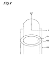
Another example of the optical fiber is
disclosed in Japanese Laid-open Patent Application No.
3-245108. As shown in Fig. 7, this optical fiber 100
has a core 101, which contains a glass base material
and in which a refractive index profile of a parabolic
profile type is formed across the whole core diameter,
and a cladding 102, which is made of a plastic
material having a constant index of refraction smaller
than those of the core 101. The refractive index
profile of the core 101 is established by a
concentration distribution of a dopant, such as Ge,
added into the core 101. The refractive index of the
cladding 102 is not less than 0.97 and not more than
0.985 times that of the outer peripheral portion of
the core 101, and a difference is made in the
refractive index at the border between the core 101
and the cladding 102, thereby attaining a high
numerical aperture (NA).
Further, Japanese Patent Publication No. Hei 3-18161
discloses the optical fiber having a center core,
a low index core disposed outside thereof and having a
smaller refractive index than that of the center core,
and a cladding region disposed further outside thereof.
This optical fiber has zero dispersion in the 1.5 µm
band and is thus a single-mode optical fiber therein.
Further, the relative index difference thereof is more
than 0.004 but not more than 0.014.
Having studied the above-mentioned conventional
optical fibers, the inventors have found the following
problems.
Namely, since the optical fiber disclosed in
Japanese Laid-open Patent Application No. 7-218734 has
the core made of one kind of material and having the
constant refractive index, the optical fiber, if
having a large diameter causes the modal dispersion,
so that a transmitted signal band becomes narrow.
Also, since in the optical fiber 100 disclosed
in Japanese Laid-open Patent Application No. 3-245108
the index profile of the parabolic profile type is
formed across the whole core diameter, if the core
diameter of the optical fiber 100 is not less than 100
µm, an amount of the dopant added is large, so as to
increase the production cost. Since the dopant in
glass is distributed across the whole core diameter
upon synthesis of the core 101, it is hard to
precisely control the distribution of the dopant if
the core diameter of the optical fiber is large, and
thus productivity of optical fiber cannot be improved
well.
Further, the optical fiber disclosed in Japanese
Patent Publication No. Hei 3-18161 is the single-mode
optical fiber and has considerably small relative
index difference. Therefore, this optical fiber has
the low numerical aperture (NA), and the loss due to
bending thus increases.
It is an object of the present invention to
provide a large-diameter optical fiber having a wide
bandwidth and a small bending loss and being produced
at low cost with high productivity.
An optical fiber of the present invention
comprises an inner core having a refractive index
profile in which refractive indices increase toward
the center axis thereof, an outer core provided
outside of the inner core and having a constant
refractive index not more than the minimum refractive
index of the inner core, and a cladding provided
outside of the outer core and containing a plastic
material having a smaller refractive index than that
of the outer core, wherein total refractive index
difference (Δntotal), defined as the difference between
the maximum refractive index of the inner core and the
refractive index of the cladding, is not less than
0.015 and not more than 0.1; and a outside core
diameter of the outer core (d1) is not less than 100 µm
and not more than 500 µm.
Thus, the optical fiber of the present invention
has the refractive index profile with increasing
refractive indices toward the center axis only in the
inner core, which has a smaller diameter than that of
the outer core. In comparison to optical fibers having
the above refractive index profile across the whole
core diameter, it is easier to precisely control the
index profile and obtain the desired refractive index
profile in optical fibers of the present invention
having an outer core with a large diameter. Also,
since the cladding of the optical fiber of the present
invention contains the plastic material, it becomes
possible to set the total refractive index difference
(Δntotal) larger than that of the optical fiber where
the cladding contains a glass material. Further, when
the value of Δntotal is less than 0.015, the bending
loss increases; when the value of Δntotal is over 0.1,
fabrication of the optical fiber becomes difficult and
its cost increases. When the outside core diameter of
the outer core (d1) is less than 100 µm, it is
necessary to use a precise and expensive optical
connector for coupling with this optical fiber; when
the outside core diameter of the outer core (d1) is
over 500 µm, the volume of the fiber increases, so as
to increase the production cost and the stiffness of
the optical fiber. Thus handing of the fiber becomes
difficult.
The present invention will be more fully
understood from the detailed description given
hereinbelow and the accompanying drawings, which are
given by way of illustration only and are not to be
considered as limiting the present invention.
Further scope of applicability of the present
invention will become apparent from the detailed
description given hereinafter. However, it should be
understood that the detailed description and specific
examples, while indicating preferred embodiments of the
invention, are given by way of illustration only, since
various changes and modifications within the spirit and
scope of the invention will be apparent to those
skilled in the art from this detailed description.
The preferred embodiments of the optical fiber
according to the present invention will be described
in detail by reference to Fig. 1 to Fig. 3. Fig. 1 is
a drawing to show the relation between an optical
fiber of the present invention and the refractive
index profile along the diameter corresponding to this
optical fiber.
As shown in Fig. 1, the optical fiber 10 has an
inner core 1, an outer core 2 provided outside of this
inner core 1 and having a constant refractive index
not more than the minimum refractive index of the
inner core 1, and a cladding 3 provided outside of the
outer core 2 and having a constant refractive index
smaller than that of the outer core 2.
The inner core 1 contains a material that can
sufficiently decrease the loss of light propagating
inside thereof, for example silica glass. The inner
core 1 contains a dopant for increasing the refractive
index, added in the silica glass. Examples of the
dopant are Ge, Ti, P, B, F, Al, and so on.
Concentrations of the dopant continuously increase
with nearing the center axis A of the inner core 1.
Therefore, the refractive indices increase toward the
center axis A. This refractive index profile is, for
example, a refractive index profile of the αth power
profile type. Namely, the refractive indices are
proportional to the αth power of distance along the
diameter from the center axis A. Reasons why the
refractive index profile of the αth power profile type
is employed are to decrease the effect of the modal
dispersion in the optical fiber 10 and to broaden the
bandwidth.
Values for α are preferably 1.5-5. If the value
of α is off the above range, there will appear such
tendencies that it becomes harder to produce the
desired refractive index profile and that, even if the
refractive index profile is produced, the core becomes
more fragile and the bandwidth of the optical fiber 10
becomes narrower. It is noted that α does not have to
be constant as long as the refractive index profile
has the refractive indices increasing toward the
center axis A. Namely, α may take different values
between in a portion near the center axis A and in a
portion apart therefrom.
The maximum refractive index of the inner core 1
is preferably 1.450-1.500. In this case, a doping
amount of the dopant is 1-20 wt% per silica glass 100
wt%. The core diameter of the inner core 1 (d2) is
preferably 150-300 µm.
The outer core 2 is preferably made of a
material that can sufficiently decrease the loss of
light passing inside thereof, similar to the inner
core 1. The refractive index of the outer core 2 is
preferably 1.400-1.480. A typical example of the
material for making this outer core 2 is silica glass.
The outside core diameter of the outer core 2 (d1) is
100-500 µm. When d1 is less than 100 µm, high molding
accuracy is required for production of a connector for
this optical fiber, which increases the production
cost. When d1 is over 500 µm, the fiber volume
increases, so as to increase the production cost and
the stiffness of the optical fiber 10, thus making
handling thereof difficult. In addition, the doping
amount of the dopant needs to be increased, which
increases the production cost. For fabrication of the
core portion comprised of an outer core portion that
will become the outer core 2 and an inner core portion
that will become the inner core 1, the inner core
portion and the outer core portion are preferably
fabricated together in terms of decreasing the optical
return loss in the border portion between the inner
core 1 and the outer core 2.
The ratio (d2/d1) of the core diameter of the
inner core 1 (d2) to the outside core diameter of the
outer core 2 (d1) is preferably 0.3-0.95 and more
preferably 0.5-0.9. When the ratio (d2/d1) is less
than 0.3, the percentage of the core diameter of the
inner core 1 (d2) tends to become smaller over the core
diameter of the outer core 2 (d1), so that the area of
the refractive index profile of the αth power profile
type becomes narrower. This narrows the bandwidth.
When the ratio (d2/d1) is over 0.95, the percentage of
the core diameter of the inner core 1 (d2) tends to
become larger over the outside core diameter of the
outer core 2 (d1), so as to increase the doping amount
of the dopant, which thus increases the production
cost.
The cladding 3 contains a plastic material in
order to make a difference in the refractive index
between the outer core 2 and the cladding 3, so as to
increase NA of the optical fiber 10. In this case,
therefore, the optical coupling efficiency increases
between the optical fiber 10 and a light source (not
illustrated) and the bending loss of the optical fiber
10 decreases. The plastic material is selected, for
example, from cyclic perfluororesin, photo-curing
acrylic fluoride resin, and so on, and preferably,
from the photo-curing acrylic fluoride resin in terms
of improvement in productivity. A photopolymerization
initiator, and a coupling agent for forming chemical
bonds with glass are added to the photo-curing acrylic
fluoride resin. The photopolymerization initiator is
selected, for example, from benzophenone, acetophenone,
benzyl benzoin, benzoyl peroxide, α,α'-azobisisobutyronitrile,
2-hydroxy-2-methyl-1-phenylpropan-1-one,
and so on. The coupling agent is
selected, for example, from trimethoxyvinylsilane,
methacryloxypropyltrimethoxysilane,
dimethylethoxyvinylsilane, and so on. The refractive
index of the cladding 3 is preferably 1.30-1.45. The
outside diameter of the cladding 3 is preferably 170-350
µm.
The ratio (d1/dclad) of the outside core diameter
of the outer core 2 (d1) to the outside diameter of the
above cladding 3 (dclad) is preferably 0.8-0.95. When
the ratio (d1/dclad) is less than 0.8, the optical
coupling efficiency decreases between the optical
fiber 10 and another optical fiber or a light source
to be coupled therewith. When the ratio (d1/dclad) is
over 0.95, the percentage of the cladding 3 containing
the plastic material becomes smaller, so that the
optical fiber 10 tends to become harder to bend.
The total refractive index difference
(hereinafter referred to as Δntotal), defined as the
difference between the maximum refractive index of the
inner core 1 and the refractive index of the cladding
3, is 0.015-0.1. When Δntotal is less than 0.015, the
bending loss increases and the problem of eye-safety
occurs. When Δntotal is over 0.1, fabrication of the
optical fiber 10 becomes difficult and costs high, and
the transmission characteristics (particularly the
bandwidth) degrade.
The ratio (Δn2/Δntotal) is preferably 0.2-0.9 and
more preferably 0.5-0.85, Δn2 being defined as the
difference between the maximum refractive index and
the minimum refractive index in the inner core 1. When
(Δn2/Δntotal) is less than 0.2, the area of the index
profile of the αth power profile type becomes narrower
and thus there is a tendency that the bandwidth cannot
be widened. When (Δn2/Δntotal) is over 0.9, in the case
where the inner core 1 is made by addition of a fixed
amount of the dopant, the difference in the refractive
index of the cladding 3 and the outer core 2 is small,
so that the effective NA decreases and the bending
loss increases; in the case where the doping amount of
the dopant is increased in order to increase Δn2 (or
the maximum refractive index of the inner core 1), the
core portion that will become the inner core 1 and
outer core 2 tends to become more fragile.
Next described is an example of a method for
fabricating the optical fiber 10 having the above
structure.
First, the core portion to become the inner core
1 and outer core 2 of the optical fiber 10 is produced
in the following manner, using the VAD process.
Specifically, a glass rod of silica is first prepared.
Then this glass rod is kept standing vertically. Then
flame is ejected from a burner for the inner core to
the central part at the bottom end of the glass rod
and from a burner for the outer core to the peripheral
part. The temperatures of the bottom end of the glass
rod are 600-800 °C in the central part and 300-600 °C
in the peripheral part. In this case, SiCl4 gas, GeCl4
gas, hydrogen gas, and oxygen gas are simultaneously
fed to the inner core burner and SiCl4 gas, hydrogen
gas, and oxygen gas are simultaneously fed to the
outer core burner. As a result, silica particles are
deposited on the central part at the bottom end of the
glass rod and germanium is taken in this central part.
The nearer to the center axis A, the larger
concentrations of germanium; the farther from the
center axis A, the smaller the concentrations of
germanium.
At this time, the glass rod is pulled up with
being rotated so that the position of the bottom
surface is always constant. At the bottom end of the
glass rod a porous glass deposit is formed by heating
with the burners. This glass deposit is sintered
through a carbon heater of a ring shape while being
pulled up, thus obtaining the core portion comprised
of the inner core portion expected to be the inner
core 1 and the outer core portion expected to be the
outer core 2.
Then the core portion thus obtained is set in a
cylindrical drawing furnace and then drawing is
conducted with heating the bottom end of the core
portion, thus forming the core consisting of the inner
core 1 and the outer core 2. Then this core is allowed
to pass through a die charged with the material for
formation of the cladding containing the photo-curing
acrylic fluoride resin as the plastic material, the
photopolymerization initiator, and the coupling agent,
thereby coating the outside of the core with the clad-forming
material. Then this clad-forming material is
exposed to ultraviolet rays, so as to cure the clad-forming
material, thereby obtaining the optical fiber
10 having the outside diameter of 100-500 µm.
The aforementioned optical fiber 10 has the
refractive index profile with increasing refractive
indices toward the center axis A only in the inner
core 1, which has the smaller diameter than that of
the outer core 2. Accordingly, in comparison to
optical fibers having the above refractive index
profile across the whole core diameter, the doping
amount of the expensive dopant such as Ge can be
smaller in this structure in optical fiber 10 having
outer core 2 with a large diameter. The production
cost of the optical fiber 10 can be decreased
accordingly. It also becomes easier to precisely
control the dopant concentration distribution, so that
the refractive index profile in the inner core 1 can
be accurately controlled in the ideal αth power
profile type. This results in improving the
productivity of optical fiber 10. Also, since the
cladding 3 contains the plastic material, the total
refractive index difference (Δntotal) can be larger than
in the case where the cladding 3 contains the glass
material, and thus NA of the optical fiber 10 can be
greater. Therefore, the optical fiber 10 can increase
the optical coupling efficiency between the optical
fiber 10 and the light source and can sufficiently
decrease the bending loss of the optical fiber 10.
Further, the optical fiber 10 can be formed with
the bandwidth of 500 MHz·100 m or more at either
wavelength in the range between 570 nm inclusive and
850 nm inclusive by adjusting the ratio (d2/d1) of the
core diameter of the inner core 1 (d2) to the core
diameter of the outer core 2 (d1), and (Δn2/Δntotal). For
example, at the wavelength of 650 nm, as shown in Fig.
2, the bandwidth of 500-3000 MHz can be attained with
the optical fiber 10 by suitably adjusting the ratio
(d2/d1) and (Δn2/Δntotal). In Fig. 2, "a" represents an
area of the bandwidth 2500-3000 (MHz·100 m), "b" an
area of the bandwidth 2000-2500 (MH·100 m), "c" an
area of the bandwidth 1500-2000 (MHz·100 m), "d" an
area of the bandwidth 1000-1500 (MH·100 m), "e" an
area of the bandwidth 500-1000 (MHz·100 m), and "f" an
area of the bandwidth 0-500 (MH·100 m).
It is noted that the present invention is by no
means limited to the embodiment described above. For
example, the inner core 1 and outer core 2 may contain
a plastic material, in the optical fiber 10. The
optical fiber 10 may be made in the structure wherein
the inner core 1 contains the silica glass while the
outer core 2 contains the plastic material; or,
conversely, in the structure wherein the inner core 1
contains the plastic material while the outer core 2
contains the silica glass.
In the above production of the optical fiber 10
the core portion that will become the outer core 2 and
the inner core 1 is made together using the VAD
process, but the core portion may be formed in two
steps by a method of forming the inner core portion by
the VAD process, thereafter inserting the inner core
portion into a hollow outer core portion made
separately from the inner core portion, and collapsing
the outer core portion.
In the above embodiment the refractive index
profile in the inner core 1 smoothly changes toward
the center axis, but the profile may also change
stepwise along a second power (parabolic) profile
curve C indicated by a dashed line, as shown in Fig. 3.
In this case the second power profile curve C passes
middle points of respective steps.
The present invention will be described more
specifically with examples, but it should be noted
that the present invention is not intended to be
limited thereby.
Prepared was the core with the inner core 1 and
outer core 2 made of the base material of silica glass
having the refractive index of 1.458 wherein Ge
(additive amount: 8.2 wt%) was added per SiO 2 100 wt%
in the inner core 1. The core having the outside
diameter of 200 µm was obtained by first preparing the
core portion to become the core by the VAD process and
then drawing the core portion. Further, the outside of
the core was coated with the material for forming the
cladding as follows. This clad-forming material was a
mixture of compounds represented by the following
chemical formulas (1)-(4):
 and
and
the photopolymerization initiator (2-hydroxy-2-methyl-1-phenylpropan-1-one) and the coupling agent (dimethylethoxyvinylsilane) (5);
wherein the mixture (the refractive index 1.423) had the following composition (weight ratio):
(1):(2):(3):(4):(5) = 10:52:15:18:5.
The optical fiber was produced in this way. For this optical fiber, the refractive index profile was measured using a preform analyzer (P104 refractive index profile measuring apparatus available from Seiko Denshi Kogyo). The result was shown in Fig. 4. This optical fiber was evaluated as to the transmission bandwidth and the loss due to bending of the optical fiber. The results were shown in Table 1.
In Table 1, the evaluation of the bending loss is
based on the following criteria; "1" stands for the
case where the bending loss was less than 0.05 dB; "2"
for the case where the bending loss was not less than
0.05 dB and not more than 0.08 dB; "3" for the case
where the bending loss was over 0.08 dB;
"unmeasurable" for the case where the bending loss was
unable to be measured.
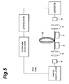
The transmission bandwidths were measured by the
frequency sweep method using the apparatus shown in
Fig. 5. In Fig. 5, numeral 4 designates LD (NA = 0.3)
of the wavelength 650 nm, 5, 8 lenses, 6, 7 XYZ stage,
and 9 APD (the diameter of the light receiving surface
thereof is 0.2 mm).
The bending losses were measured using the
apparatus shown in Fig. 6. In Fig. 6, numeral 11
designates LD of the wavelength 650 nm, 12 lenses, 13
XYZ stage, 14 a mandrel of the diameter 20 mm, and 15
a sensor adapter. For the measurement, ten windings of
the optical fiber 10 were made around the mandrel 14.
An optical fiber was produced in the same manner
as in Example 1 except that the core diameter of the
inner core 1 (d2) was decreased, and the transmission
bandwidth and bending loss were measured for this
optical fiber in the same manner as in Example 1. As
apparent from the results shown in Table 1, the
transmission bandwidth was smaller than that of the
optical fiber of Example 1 but was still sufficiently
wide. The bending loss was nearly equal to that of the
optical fiber of Example 1.
An optical fiber was produced in the same manner
as in Example 1 except that the core diameter of the
inner core 1 (d2) was decreased, and the transmission
bandwidth and bending loss were measured for this
optical fiber in the same manner as in Example 1. As
apparent from the results shown in Table 1, the
transmission bandwidth was smaller than that of the
optical fiber of Example 1 but larger than that of the
optical fiber of Example 2, and was still sufficiently
wide. The bending loss was nearly equal to that of the
optical fiber of Example 1.
An optical fiber was produced in the same manner
as in Example 1 except that the core diameter of the
inner core 1 (d2) was increased, and the transmission
bandwidth and bending loss were measured for this
optical fiber in the same manner as in Example 1. As
apparent from the results shown in Table 1, the
transmission bandwidth was considerably greater than
that of the optical fiber of Example 1 and was over 2
GHz·100m. The bending loss was nearly equal to that of
the optical fiber of Example 1.
An optical fiber was produced in the same manner
as in Example 1 except that the cladding was made of a
mixture (the refractive index 1.418) of the compounds
(1)-(5) in Example 1 in the following composition
(weight ratio):
(1):(2):(3):(4):(5) = 10:60:10:15:5
and that Δn2 was decreased, and the transmission bandwidth and bending loss were measured for this optical fiber in the same manner as in Example 1. As apparent from the results shown in Table 1, the transmission bandwidth was smaller than that of the optical fiber of Example 1 but was still sufficiently wide. The bending loss was nearly equal to that of the optical fiber of Example 1.
An optical fiber was produced in the same manner
as in Example 1 except that the cladding was made of a
mixture (the refractive index 1.438) of the compounds
(1)-(5) in Example 1 in the following composition
(weight ratio)
(1):(2):(3):(4):(5) = 10:40:15:30:5
and that Δn2 was increased, and the transmission bandwidth and bending loss were measured for this optical fiber in the same manner as in Example 1. As apparent from the results shown in Table 1, the transmission bandwidth was a little larger than that of the optical fiber of Example 1. The bending loss was nearly equal to that of the optical fiber of Example 1.
An optical fiber was produced in the same manner
as in Example 1 except that the cladding was made of a
mixture (the refractive index 1.394) of the compounds
(1)-(5) in Example 1 in the following composition
(weight ratio)
(1):(2):(3):(4):(5) = 10:75:5:5:5,
that Δn2 was decreased, and that Δntotal was increased, and the transmission bandwidth and bending loss were measured for this optical fiber in the same manner as in Example 1. As apparent from the results shown in Table 1, the transmission bandwidth was smaller than that of the optical fiber of Example 1 but was still sufficiently wide. The bending loss was good as being less than that of the optical fiber of Example 1.
An optical fiber was produced in the same manner
as in Example 1 except that the refractive index
profile of the inner core 1 was a 1.5th power profile
(α = 1.5), and the transmission bandwidth and bending
loss were measured for this optical fiber in the same
manner as in Example 1. As apparent from the results
shown in Table 1, the transmission bandwidth was
smaller than that of the optical fiber of Example 1
but was still sufficiently wide. The bending loss was
nearly equal to that of the optical fiber of Example 1.
An optical fiber was produced in the same manner
as in Example 1 except that the refractive index
profile of the inner core 1 was a third power profile
(α = 3), and the transmission bandwidth and bending
loss were measured for this optical fiber in the same
manner as in Example 1. As apparent from the results
shown in Table 1, the transmission bandwidth was
smaller than that of the optical fiber of Example 1
but was still sufficiently wide. The bending loss was
nearly equal to that of the optical fiber of Example 1.
An optical fiber was produced in the same manner
as in Example 1 except that the refractive index
profile of the inner core 1 was a fifth power profile
(α = 5), and the transmission bandwidth and bending
loss were measured for this optical fiber in the same
manner as in Example 1. As apparent from the results
shown in Table 1, the transmission bandwidth was
smaller than that of the optical fiber of Example 1
but was still sufficiently wide. The bending loss was
nearly equal to that of the optical fiber of Example 1.
An optical fiber was produced in the same manner
as in Example 1 except that the outside diameter of
the cladding 3 was decreased, and the transmission
bandwidth and bending loss were measured for this
optical fiber in the same manner as in Example 1. As
apparent from the results shown in Table 1, the
transmission bandwidth and bending loss were both
nearly equal to those of the optical fiber of Example
1.
An optical fiber was produced in the same manner
as in Example 1 except that the outside diameter of
the cladding 3 was increased, and the transmission
bandwidth and bending loss were measured for this
optical fiber in the same manner as in Example 1. As
apparent from the results shown in Table 1, the
transmission bandwidth and bending loss were both
nearly equal to those of the optical fiber of Example
1.
An optical fiber was produced in the same manner
as in Example 1 except that d1, d2, and dclad were
decreased, and the transmission bandwidth and bending
loss were measured for this optical fiber in the same
manner as in Example 1. As apparent from the results
shown in Table 1, the transmission bandwidth and
bending loss were both nearly equal to those of the
optical fiber of Example 1.
An optical fiber was produced in the same manner
as in Example 1 except that d1, d2, and dclad were
increased, and the transmission bandwidth and bending
loss were measured for this optical fiber in the same
manner as in Example 1. As apparent from the results
shown in Table 1, the transmission bandwidth and
bending loss were both nearly equal to those of the
optical fiber of Example 1.
An optical fiber was produced in the same manner
as in Example 5 except that Δn2 and Δntotal were
decreased, and the transmission bandwidth and bending
loss were measured for this optical fiber in the same
manner as in Example 1. As apparent from the results
shown in Table 1, the bandwidth was a little narrower
than that of the optical fiber of Example 5, but was
still sufficiently wide. The bending loss was nearly
equal to that of the optical fiber of Example 1.
An optical fiber was produced so as to have the
cladding (the refractive index 1.408) made of a
mixture of the compounds (1)-(5) in Example 1 in the
following composition (weight ratio):
(1):(2):(3):(4):(5) = 10:68:5:12:5;
and the core (the refractive index 1.423) in which the refractive index profile of the step index type was formed, made of a mixture of the compounds (1)-(5) in Example 1 in the following composition (weight ratio):
(1):(2):(3):(4):(5) = 10:52:15:18:5,
and the transmission bandwidth and bending loss were measured for this optical fiber in the same manner as in Example 1. The results were shown in Table 2.
As shown in Table 2, the bending loss was nearly
equal to that of Example 1, but the transmission
bandwidth was considerably smaller than that of the
optical fiber of Example 1.
An optical fiber was produced so as to have the
cladding (the refractive index 1.502) made of a
mixture of the compounds (1)-(5) in Example 1 in the
following composition (weight ratio):
(1):(2):(3):(4):(5) = 0:0:25:70:5;
and the core in which Ge (the doping amount: 8.2 wt%) was distributed throughout the whole diameter in silica glass having the refractive index of 1.502, and the transmission bandwidth and bending loss were measured for this optical fiber in the same manner as in Example 1. The results were shown in Table 2. As shown in Table 2, the transmission bandwidth was over 2 GHz·100 m, sufficiently greater than that of the optical fiber of Example 1, but the bending loss was not sufficient, considerably larger than that of the optical fiber of Example 1. Since Ge was distributed throughout the whole core, the production cost was higher than that of the optical fiber of Example 1.
An optical fiber was produced in the same manner
as in Comparative Example 2 except that Δn2 and Δntotal
were increased, and the transmission bandwidth and
bending loss were measured for this optical fiber in
the same manner as in Example 1. The results were
shown in Table 2. As shown in Table 2, the
transmission bandwidth was over 2 GHz·100 m,
sufficiently greater than that of the optical fiber of
Example 1, but the bending loss was considerably
larger than that of the optical fiber of Example 1 and
thus not sufficient. Since Ge was distributed
throughout the whole core, the production cost was
higher than that of the optical fiber of Example 1.
An optical fiber was produced in the same manner
as in Example 1 except that Δn2 and Δntotal were
decreased and that the cladding was made of silica
glass of the refractive index 1.453, and the
transmission bandwidth and bending loss were measured
for this optical fiber in the same manner as in
Example 1. The results were shown in Table 2. As
shown in Table 2, the transmission bandwidth was
greater than that of the optical fiber of Example 1,
but the bending loss was greater than that of the
optical fiber of Example 1 and not sufficient.
An optical fiber was produced in the same manner
as in Example 1 except that d1 and d2 were decreased,
and the transmission bandwidth and bending loss were
measured for this optical fiber in the same manner as
in Example 1. The results were shown in Table 2. As
shown in Table 2, neither the transmission bandwidth
nor the bending loss was able to be measured, because
the intensity of emitted light was not stable.
An optical fiber was produced in the same manner
as in Example 1 except that d1 and d2 were increased,
and the transmission bandwidth and bending loss were
measured for this optical fiber in the same manner as
in Example 1. The results were shown in Table 2. As
shown in Table 2, the transmission bandwidth was
nearly equal to that of the optical fiber of Example 1,
but the bending loss was unable to be measured,
because the optical fiber was broken when bent.
As detailed above, the present invention makes
it easier in the case where the outer core has a large
diameter, to precisely control the refractive index
profile of the inner core and in turn to form the
desired index profile in the inner core, than in the
case where the refractive index profile is formed with
increasing refractive indices toward the center axis
across the whole core diameter. This increases the
productivity of optical fiber. Since the cladding
contains the plastic material, the total refractive
index difference (Δntotal) can be set large, whereby the
optical coupling efficiency can be increased between
the optical fiber and the light source to be coupled
therewith and whereby the bending loss of optical
fiber can be decreased.
From the invention thus described, it will be
obvious that the invention may be varied in many ways.
Such variations are not to be regarded as a departure
from the spirit and scope of the invention, and all
such modifications as would be obvious to one skilled
in the art are intended for inclusion within the scope
of the following claims.
Claims (5)
- An optical fiber comprising:an inner core having a refractive index profile in which refractive indices increase toward the center axis thereof;an outer core provided outside of said inner core and having a constant refractive index not more than the minimum refractive index of said inner core; anda cladding provided outside of said outer core and having a refractive index smaller than said constant refractive index of said outer core;
wherein total refractive index difference (Δntotal), defined as the difference between the maximum refractive index of said inner core and the refractive index of said cladding, is not less than 0.015 and not more than 0.1; and a outside core diameter (d1) of said outer core is not less than 100 µm and not more than 500 µm. - The optical fiber according to Claim 1, wherein the ratio (d2/d1) of the core diameter of the inner core (d2) to the outside core diameter of the outer core (d1) is not less than 0.3 and not more than 0.95 and the ratio (Δn2/Δntotal) is not less than 0.2 and not more than 0.9, Δn2 being defined as the difference between the maximum refractive index and the minimum refractive index in said inner core.
- The optical fiber according to Claim 1, wherein the refractive index profile in said inner core is an αth power profile, where α has a value of not less than 1.5 and not more than 5.
- The optical fiber according to Claim 1, wherein the ratio (d1/dclad) of the core diameter of said outer core (d1) to the outside diameter of said cladding (dclad) is not less than 0.8 and not more than 0.95.
- The optical fiber according to Claim 1, wherein said inner core and said outer core contain silica glass.
Applications Claiming Priority (2)
| Application Number | Priority Date | Filing Date | Title |
|---|---|---|---|
| JP157030/97 | 1997-06-13 | ||
| JP15703097 | 1997-06-13 |
Publications (1)
| Publication Number | Publication Date |
|---|---|
| EP0884614A1 true EP0884614A1 (en) | 1998-12-16 |
Family
ID=15640660
Family Applications (1)
| Application Number | Title | Priority Date | Filing Date |
|---|---|---|---|
| EP98110647A Withdrawn EP0884614A1 (en) | 1997-06-13 | 1998-06-10 | Optical fiber |
Country Status (2)
| Country | Link |
|---|---|
| US (1) | US6078715A (en) |
| EP (1) | EP0884614A1 (en) |
Cited By (6)
| Publication number | Priority date | Publication date | Assignee | Title |
|---|---|---|---|---|
| WO2001040835A3 (en) * | 1999-12-06 | 2002-03-07 | Cidra Corp | Large diameter optical waveguide, grating, and laser |
| US6621957B1 (en) | 2000-03-16 | 2003-09-16 | Cidra Corporation | Temperature compensated optical device |
| EP1412786A1 (en) * | 2001-02-06 | 2004-04-28 | Phonon Technologies Corporation | Low loss isotopic optical waveguides |
| US6810178B2 (en) | 1998-12-04 | 2004-10-26 | Cidra Corporation | Large diameter optical waveguide having blazed grating therein |
| US6996316B2 (en) | 1999-09-20 | 2006-02-07 | Cidra Corporation | Large diameter D-shaped optical waveguide and coupler |
| CN104316993A (en) * | 2014-10-29 | 2015-01-28 | 长飞光纤光缆股份有限公司 | Energy transmission optical fiber with large core diameter |
Families Citing this family (15)
| Publication number | Priority date | Publication date | Assignee | Title |
|---|---|---|---|---|
| US6292612B1 (en) * | 1999-06-07 | 2001-09-18 | Lucent Technologies Inc. | Multi-mode optical fiber having improved refractive index profile and devices comprising same |
| US6490396B1 (en) | 1999-09-29 | 2002-12-03 | Corning Incorporated | Optical waveguide fiber |
| US6512871B2 (en) * | 2001-02-12 | 2003-01-28 | Gazillion Bits, Inc. | Dispersion compensating fiber with void pattern in secondary core |
| US6959022B2 (en) * | 2003-01-27 | 2005-10-25 | Ceramoptec Gmbh | Multi-clad optical fiber lasers and their manufacture |
| US6952519B2 (en) * | 2003-05-02 | 2005-10-04 | Corning Incorporated | Large effective area high SBS threshold optical fiber |
| US7590319B2 (en) * | 2004-02-06 | 2009-09-15 | Fujifilm Corporation | Preform for plastic optical material, production method thereof, optical coupling method of plastic optical fiber and connector used for optical coupling |
| KR100594062B1 (en) * | 2004-02-13 | 2006-06-30 | 삼성전자주식회사 | Optical fiber having the low discontinuity of the residual stress |
| US7082243B2 (en) * | 2004-04-05 | 2006-07-25 | Corning Incorporated | Large effective area high SBS threshold optical fiber |
| WO2006022357A1 (en) * | 2004-08-23 | 2006-03-02 | Fujifilm Corporation | Optical connection method and optical transmission apparatus |
| CN101558338B (en) * | 2007-03-16 | 2011-01-19 | 株式会社藤仓 | Polymer-clad optical fiber |
| EP2161601B1 (en) | 2007-06-26 | 2018-05-30 | Fujikura Ltd. | Plastic glass optical fiber |
| US20100154478A1 (en) * | 2008-12-01 | 2010-06-24 | Panduit Corp. | Multimode fiber having improved index profile |
| EP2534511A4 (en) * | 2010-02-09 | 2017-12-27 | OFS Fitel, LLC | Improvement of dmd performance in bend optimized multimode fiber |
| WO2012142187A2 (en) * | 2011-04-11 | 2012-10-18 | The Regents Of The University Of California | Systems and methods for fiber optic parametric amplification and nonlinear optical fiber for use therein |
| US10983267B2 (en) | 2018-03-08 | 2021-04-20 | Corning Incorporated | Quasi-single-mode optical fiber |
Citations (4)
| Publication number | Priority date | Publication date | Assignee | Title |
|---|---|---|---|---|
| GB1475478A (en) * | 1975-11-28 | 1977-06-01 | Jenaer Glaswerk Schott & Gen | Multimode light guide |
| GB2185331A (en) * | 1985-09-02 | 1987-07-15 | Nippon Telegraph & Telephone | Single mode optical fibre |
| DE3804152A1 (en) * | 1988-02-11 | 1989-08-24 | Rheydt Kabelwerk Ag | OPTICAL FIBER |
| EP0689068A1 (en) * | 1994-06-24 | 1995-12-27 | Sumitomo Electric Industries, Ltd. | Single mode optical fiber |
Family Cites Families (7)
| Publication number | Priority date | Publication date | Assignee | Title |
|---|---|---|---|---|
| JPH0318161A (en) * | 1989-06-15 | 1991-01-25 | Toshiba Corp | Telephone set |
| JP3132729B2 (en) * | 1990-02-23 | 2001-02-05 | 住友電気工業株式会社 | Broadband high NA optical fiber |
| JP3134648B2 (en) * | 1994-01-28 | 2001-02-13 | 住友電気工業株式会社 | Plastic clad optical fiber |
| FR2724022B1 (en) * | 1994-08-25 | 1996-09-20 | Alcatel Fibres Optiques | OPTICAL FIBER COMPRISING A PROTECTIVE LAYER, AND METHOD FOR MANUFACTURING SUCH FIBER |
| KR0162604B1 (en) * | 1994-10-07 | 1999-04-15 | 김광호 | Optical fiber preform making method |
| WO1997008791A1 (en) * | 1995-08-31 | 1997-03-06 | Sdl, Inc. | Optical fibre for improved power coupling |
| US5841926A (en) * | 1996-01-04 | 1998-11-24 | Nippon Telegraph And Telephone Corporation | Optical fibers for optical attenuation |
-
1998
- 1998-06-10 EP EP98110647A patent/EP0884614A1/en not_active Withdrawn
- 1998-06-12 US US09/096,743 patent/US6078715A/en not_active Expired - Fee Related
Patent Citations (4)
| Publication number | Priority date | Publication date | Assignee | Title |
|---|---|---|---|---|
| GB1475478A (en) * | 1975-11-28 | 1977-06-01 | Jenaer Glaswerk Schott & Gen | Multimode light guide |
| GB2185331A (en) * | 1985-09-02 | 1987-07-15 | Nippon Telegraph & Telephone | Single mode optical fibre |
| DE3804152A1 (en) * | 1988-02-11 | 1989-08-24 | Rheydt Kabelwerk Ag | OPTICAL FIBER |
| EP0689068A1 (en) * | 1994-06-24 | 1995-12-27 | Sumitomo Electric Industries, Ltd. | Single mode optical fiber |
Cited By (10)
| Publication number | Priority date | Publication date | Assignee | Title |
|---|---|---|---|---|
| US6810178B2 (en) | 1998-12-04 | 2004-10-26 | Cidra Corporation | Large diameter optical waveguide having blazed grating therein |
| US6996316B2 (en) | 1999-09-20 | 2006-02-07 | Cidra Corporation | Large diameter D-shaped optical waveguide and coupler |
| WO2001040835A3 (en) * | 1999-12-06 | 2002-03-07 | Cidra Corp | Large diameter optical waveguide, grating, and laser |
| US6982996B1 (en) | 1999-12-06 | 2006-01-03 | Weatherford/Lamb, Inc. | Large diameter optical waveguide, grating, and laser |
| US7437043B2 (en) | 1999-12-06 | 2008-10-14 | Weatherford/Lamb, Inc. | Large diameter optical waveguide, grating and laser |
| US8111963B2 (en) | 1999-12-06 | 2012-02-07 | Weatherford/Lamb, Inc. | Large diameter optical waveguide, grating and laser |
| US8244088B2 (en) | 1999-12-06 | 2012-08-14 | Weatherford/Lamb, Inc. | Large diameter optical waveguide, grating and laser |
| US6621957B1 (en) | 2000-03-16 | 2003-09-16 | Cidra Corporation | Temperature compensated optical device |
| EP1412786A1 (en) * | 2001-02-06 | 2004-04-28 | Phonon Technologies Corporation | Low loss isotopic optical waveguides |
| CN104316993A (en) * | 2014-10-29 | 2015-01-28 | 长飞光纤光缆股份有限公司 | Energy transmission optical fiber with large core diameter |
Also Published As
| Publication number | Publication date |
|---|---|
| US6078715A (en) | 2000-06-20 |
Similar Documents
| Publication | Publication Date | Title |
|---|---|---|
| US6078715A (en) | Optical fiber | |
| US9796618B2 (en) | Multi-core optical fiber ribbons and methods for making the same | |
| JP5687355B2 (en) | Multimode optical fiber with bending resistance, large core diameter and high numerical aperture | |
| JP5636151B2 (en) | Multi-wavelength, multimode optical fiber | |
| US7702204B2 (en) | Method for manufacturing an optical fiber preform | |
| AU648181B2 (en) | Method of making polarization retaining fiber | |
| US10775558B2 (en) | Low loss wide bandwidth optical fiber | |
| US6205279B1 (en) | Single mode optical fiber having multi-step core structure and method of fabricating the same | |
| EP2426533B1 (en) | Method of fabricating an optical fiber preform | |
| JP2007011366A (en) | Low loss optical fiber and manufacturing method thereof | |
| JPH1164665A (en) | Optical fiber | |
| US20070204657A1 (en) | Manufacture of depressed index optical fibers | |
| CN106371167A (en) | High-bandwidth multi-mode fiber | |
| JP2001235648A (en) | Preform for multimode fiber and multimode fiber | |
| US11579355B2 (en) | Low cross-talk multicore optical fiber for single mode operation | |
| US20220066090A1 (en) | Multicore optical fiber with depressed index common cladding | |
| EP0083843B1 (en) | Low dispersion, low-loss single-mode optical waveguide | |
| US7046890B2 (en) | Optical fiber with low taper induced loss | |
| US5683486A (en) | Method of forming a fiber preform to minimize shifts of the zero-dispersion wavelength | |
| CN1300607C (en) | Bending insensitive optical fiber and preparing method thereof | |
| CA1122079A (en) | Manufacture of monomode fibers | |
| US7013678B2 (en) | Method of fabricating graded-index optical fiber lenses | |
| JPH07230015A (en) | Dispersion shift type single-mode optical fiber, and preform for the same and its manufacture | |
| CN110873925A (en) | 980 optical fiber for thin-diameter coupler | |
| GB1593488A (en) | Low loss high n a plastic clad optical fibres |
Legal Events
| Date | Code | Title | Description |
|---|---|---|---|
| PUAI | Public reference made under article 153(3) epc to a published international application that has entered the european phase |
Free format text: ORIGINAL CODE: 0009012 |
|
| AK | Designated contracting states |
Kind code of ref document: A1 Designated state(s): DE GB |
|
| AX | Request for extension of the european patent |
Free format text: AL;LT;LV;MK;RO;SI |
|
| 17P | Request for examination filed |
Effective date: 19990216 |
|
| AKX | Designation fees paid |
Free format text: DE GB |
|
| STAA | Information on the status of an ep patent application or granted ep patent |
Free format text: STATUS: THE APPLICATION HAS BEEN WITHDRAWN |
|
| 18W | Application withdrawn |
Effective date: 20060222 |