EP0881044A1 - Robot controller - Google Patents
Robot controller Download PDFInfo
- Publication number
- EP0881044A1 EP0881044A1 EP96929577A EP96929577A EP0881044A1 EP 0881044 A1 EP0881044 A1 EP 0881044A1 EP 96929577 A EP96929577 A EP 96929577A EP 96929577 A EP96929577 A EP 96929577A EP 0881044 A1 EP0881044 A1 EP 0881044A1
- Authority
- EP
- European Patent Office
- Prior art keywords
- robot
- control
- value
- flexible
- torque
- Prior art date
- Legal status (The legal status is an assumption and is not a legal conclusion. Google has not performed a legal analysis and makes no representation as to the accuracy of the status listed.)
- Granted
Links
Images


Classifications
-
- B—PERFORMING OPERATIONS; TRANSPORTING
- B25—HAND TOOLS; PORTABLE POWER-DRIVEN TOOLS; MANIPULATORS
- B25J—MANIPULATORS; CHAMBERS PROVIDED WITH MANIPULATION DEVICES
- B25J13/00—Controls for manipulators
-
- B—PERFORMING OPERATIONS; TRANSPORTING
- B25—HAND TOOLS; PORTABLE POWER-DRIVEN TOOLS; MANIPULATORS
- B25J—MANIPULATORS; CHAMBERS PROVIDED WITH MANIPULATION DEVICES
- B25J9/00—Programme-controlled manipulators
- B25J9/16—Programme controls
- B25J9/1628—Programme controls characterised by the control loop
- B25J9/1633—Programme controls characterised by the control loop compliant, force, torque control, e.g. combined with position control
-
- G—PHYSICS
- G05—CONTROLLING; REGULATING
- G05B—CONTROL OR REGULATING SYSTEMS IN GENERAL; FUNCTIONAL ELEMENTS OF SUCH SYSTEMS; MONITORING OR TESTING ARRANGEMENTS FOR SUCH SYSTEMS OR ELEMENTS
- G05B2219/00—Program-control systems
- G05B2219/30—Nc systems
- G05B2219/42—Servomotor, servo controller kind till VSS
- G05B2219/42123—Position loop then force, current loop
Definitions
- the present invention relates to a control apparatus for a robot which executes operations while switching between a position control and a flexible control.
- the present invention relates to a flexible control apparatus for a robot and the like, more particularly to a flexible control apparatus for a robot which is capable of limiting a developing force of a servo motor for driving joints based on set values for a force and a torque at an operation coordinate system. More particularly, the present invention relates to a flexible control apparatus for a robot which is capable of flexibly following an external force when it is applied thereto, by limiting a gain of a position speed control system or by limiting a developing force of a servo motor for driving joints based on a torque limitation value.
- the present invention relates to a flexible control apparatus which controls a gain of a position speed control system or limits a developing force of a servo motor for controlling joints by torque control, whereby changing a flexibility of a flexible control system in an instrument for controlling the robot for an external force. Furthermore, the present invention relates to a flexible control apparatus of a robot of a servo control which is capable of monitoring a servo deviation during flexible control of a robot and interrupting an operation or changing the kind of an operation to another when the operation is not performed normally.
- Fig. 1 illustrates a position/speed control system of a motor which has been widely used in controlling joints of a robot.
- Reference symbol s denotes a Laplace operator.
- a speed control loop gain Kv111 and a position loop gain Kp110 is set to be as high as possible, in order to perform a positioning in opposition to friction and external force. Furthermore, an integrator 113 is arranged in parallel with a proportional operator 112 whereby control is performed so as to improve its characteristics. With such a control system, the tip of the robot can be accurately positioned at their target positions even under conditions of external force.
- the foregoing robot has no ability to cope with usage for performing an operation while absorbing a strong force applied from the outside.
- the conventional position control robot aims to work in operations to flexibly receive the force applied from an external machine and in the usage of holding and pushing of parts by the robot, the accomplishment of the operations will be difficult.
- the prior art No. 2 concerns a flexible servo control method which moves a driven body by means of human power, the driven body being driven by a servo motor and is kept away from obstacles.
- the position gain Kp110a and the proportional gain Kv112a of the speed control loop are lowered in accordance with the degree of setting flexibility.
- the output from the integrator 113 of the speed control loop is limited to the value of a setting clamp.
- the torque reference will not have a specially large value in spite of an increase in the position deviation, so that the driven body to be driven by the servo motor can be moved by the human power.
- the prior art No. 2 is a technology which is capable of moving the driven body while avoiding an obstacle by human power, in the case when an obstacle is in the movement path of the driven body.
- the prior art No. 3 concerns a flexible servo control method which is capable of changing the gain of the servo system of the robot built in each of the coordinate axes by setting the flexibility on the operation coordinates.
- the prior art No. 3 is a technology in which the flexibility designated on the operation coordinates where the servo motor is positioned is converted to the servo gains Kp110a and Kv112a of the servo motor on each of the coordinate axes, the servo motor is driven by the servo gains Kp and Kv converted by the flexibility, and the body to be driven by the servo motor can be moved by human power.
- the robot when transition from the position control to the flexible control is made, the robot is affected greatly by a force acting statistically to it, particularly, by gravity. Specifically, when the flexible function starts to operate, the robot arm drops in the direction of the gravity due to the action of the gravity, so that the robot changes greatly in posture, making execution of operations difficult. Moreover, when transition from the flexible control to the position control is made, there are problems that the robot arm drops in the direction of gravity or the response is unstable for a period during which values are accumulated in the integrator of the speed control system. Moreover, during flexible control, the value of the position instruction often does not accord with the present position of the robot.
- the robot has the following problems.
- the first object of the present invention is to provide a control apparatus of a robot which is capable of achieving a smooth switching between the position control and the flexible control during the operation of the robot without being significantly affected by gravity.
- the second object of the present invention is to provide a flexible control apparatus of a robot which is capable of performing a flexibility setting for plus and minus variables with one degree of freedom and making a displacement by a large stroke, and, in addition, of performing flexible control in an operation coordinate system by a simple coordinate conversion.
- the third object of the present invention is to provide a flexible control apparatus of a robot which is capable of obtaining more flexibility in the flexible control of the robot which follows an external force applied to it, either by limiting gains of the position and speed control systems or by limiting a generation force of the servo motor for driving joints based on a torque limitation value.
- the fourth object of the present invention is to provide a flexible control apparatus of a robot which is capable of following an external force flexibly upon its application, particularly, to provide means which limits a generation force of the servo motor to drive joints by limiting gains of the position and speed control systems or a torque thereof, forces the robot to be flexibly controlled for an external force, and monitors whether operations are performed normally with safety.
- the fifth object of the present invention is to provide a flexible control apparatus of a robot which is capable of securing the safety of the operator and the robot, even when the operator contacts with the operating robot during flexible control, the operator is caught between the arms of the robot, or the robot contacts with other bodies.
- the present invention is constituted of the following means for solving the above described problems.
- a robot comprising means for switching between position control and flexible control during the operation of the robot, wherein when the transition from the position control to the flexible control is made, an integration operation of the speed control system is stopped, an integration value of the speed control system is subsequently stored in a memory and, at the same time, and the integration value is added to a torque reference or a gravity compensation value computed based on a joint angle of a robot arm, a link mass of the robot and the center of gravity thereof is added to the torque reference.
- the control apparatus of a robot is characterized in that in the operation of the robot to hold a workpiece, a mass of the workpiece is added to the foregoing gravity compensation value.
- control apparatus of a robot is characterized in that when a transition from the flexible control to the position control is made, a present position is handled as an instruction position.
- control apparatus of a robot is characterized in that when the transition from the flexible control to the position control is made, either a gravity compensation value computed based on a link mass of the robot and a position of a center of gravity thereof or an integration value of the speed control system stored in the foregoing memory is set as a new integration value of the foregoing speed control system.
- the control apparatus of a robot is characterized in that the switching between the foregoing position control and the foregoing flexible control is also performed by limiting an output value of the speed control system, that is, the torque reference value.
- a flexible control apparatus of a robot of the present invention comprises means for controlling a torque of a servo motor which drives a joint portion of the robot; means for measuring a joint angle; means for computing a very small displacement relation between coordinate systems, which are generally called Jacobian, based on information of the measured joint angle; means for converting either a force set in an operation coordinate system or a limitation value of the torque to a joint torque limitation value by use of a Jacobian's by a force acting from the outside; and means for limiting an output torque of the robot by use of the torque limitation value, wherein a flexibility setting for plus and minus variables with one degree of freedom can be performed, a displacement of a large stroke is possible, and a flexible control at an operation coordinate system with a simple coordinate conversion can be performed.
- means which is capable of varying position and speed control gains in a control system of a servo motor and feedback control means is provided, which limits an output of an integrator at a proportional integration control of a speed control loop, adds an acceleration of the servo motor multiplied by a constant to a torque reference which is a rear stage of a speed control gain multiplier, and produces an output therefrom as a new torque reference; means for limiting the foregoing torque reference to a predetermined value is provided and feedback control means is provided, which multiplies the acceleration of the servo motor by a constant to output a new torque reference.
- a flexible control apparatus of a robot comprises means for comparing a deviation between an angle reference value and a present angle in a position control system with a setting value to stop a servo motor based on the comparing result, for outputting a signal to the outside, for changing an operation schedule of a servo system, for obtaining a deviation in an operation coordinate system, for changing a flexibility of a flexible coordinate system, and for equalizing an operation coordinate system to a coordinate system of a setting value to be compared so that the setting value can be easily set.
- means which is capable of varying a position control gain and a speed control gain; means is provided which is capable of varying the position control gain and the speed control gain to other states based on reference information and detection information concerning position, speed and direction, and a computation result using the foregoing information; means is provided which limits a torque reference that is an addition result obtained by adding a proportional control to an output of an integrator; and means is provided which is capable of varying the foregoing torque limitation based on the instruction information and the detection information concerning the position, the speed and the direction, and the computation result using the foregoing information.
- a flexible control apparatus recited in claim 8 of the present invention comprises means for controlling a torque of a servo motor which drives a joint portion of the robot; means for measuring a joint angle of the foregoing joint portion; means for computing a very small displacement relation between coordinate systems based on information of the foregoing joint angle obtained by the foregoing measurement; means for converting a limitation value of either a force or a torque set in an operation coordinate system to a joint torque limitation value by use of a correspondence relation of the foregoing very small displacement; and means for limiting an output torque of the robot using the foregoing joint torque limitation value, wherein the force and torque in the operation coordinate system are converted to a limitation value of a torque in a joint coordinate system, thereby obtaining a function of the flexible control apparatus of the robot to perform a flexible movement for a force in the operation coordinate system, applied from the outside, greater than a limitation value.
- the invention recited in claim 9 of the present invention is a flexible control apparatus of a robot according to claim 8, which obtains the foregoing very small correspondence relation between the foregoing operation coordinate system and the joint coordinate system, using a reference value of the foregoing joint angle of a control system of the servo motor driving a joint portion of the robot, thereby achieving a function to make it possible to perform flexible control in the operation coordinate system with simple coordinate conversion using information of a position of the foregoing joint angle.
- the invention recited in claim 10 of the present invention is the flexible control apparatus of a robot which comprises means for varying a position control gain and a speed control gain; means for limiting an output of an integrator at a proportional integration control in the foregoing speed control loop; means for obtaining a rotation acceleration of the servo motor either by detection or by computation; and feedback control means for multiplying an acceleration of the foregoing servo motor by a constant at a rear stage of the foregoing speed control gain multiplication.
- the invention recited in claim 10 has a function in which when an external force acts on a robot in a first method, the posture of a robot begins to deviate from a position reference so that position and speed deviations will be created.
- outputs of a position control gain, a speed control gain and an integrator are so small that a torque reference is forced to be low, thereby moving a robot arm in a direction of an external force.
- the invention recited in claim 11 of the present invention is a flexible control apparatus of a robot which comprises means for controling an output of an integrator in a proportional integration control in the foregoing speed control loop; a torque limiter for limiting a torque reference that is an addition result obtained by adding an output of the foregoing integrator and that of a proportional control; means for obtaining a rotation acceleration of the foregoing motor, either by detection or by computation; and feedback control means to multiply an acceleration of the foregoing servo motor by a constant in a rear stage of the foregoing torque control limiter, and flexibility of the robot is increased.
- the invention recited in claim 12 of the present invention is a flexible control apparatus of a robot according to claim 10, which comprises means for compensating gravity or friction torque in a rear stage of adding means of a speed control and an integration control, wherein dropping in the gravity direction never occurs in spite of various changes in the posture of the robot, thereby increasing the flexibility.
- the invention recited in claim 13 of the present invention is a flexible control apparatus according to claim 11, which comprises means for compensating gravity or friction torque in a rear stage of adding means of a speed control and an integration control, wherein dropping in the gravity direction never occurs in spite of various changes in the posture of the robot, thereby increasing the flexibility.
- the invention recited in claim 14 of the present invention is a flexible control apparatus of a robot which comprises means for comparing a setting value with a difference between a target angle of a position and a present angle of the foregoing servo motor; and means for stopping a movement of the foregoing servo motor based on the comparison result.
- the invention recited in claim 14 has a function in which when a value of a position deviation is larger than a setting value, it is not judged that the present state is safe, and the robot is forced to stop the movement urgently.
- the invention recited in claim 15 of the present invention is a flexible control apparatus of a robot which comprises means for comparing a setting value with a difference between a target angle of a position and a present angle of the foregoing servo motor; and means for stopping a movement of the foregoing servo motor based on the comparison result, wherein when a value of a position deviation is larger than a setting value, a signal is sent to an external instrument using an input/output contact to stop an external instrument, for example.
- the invention recited in claim 16 of the present invention is a flexible control apparatus of a robot which comprises means for comparing a setting value with a difference between a target angle of a position and a present angle of the foregoing servo motor; and means for changing a processing of a servo control based on the comparison result, wherein branching of a condition for robot software is performed based on information of a position deviation.
- the invention recited in claim 17 of the present invention is a flexible control apparatus of a robot which comprises means for comparing a setting value with a difference between a target value in an operation coordinate system and a present value in the operation coordinate system obtained form a present value of the foregoing servo motor; and means for stopping a movement of the foregoing servo motor based on the comparison result, wherein the servo motor can be stopped based on a present position in the operation coordinate system.
- the invention recited in claim 18 of the present invention is a flexible control apparatus of a robot which comprises means for comparing a setting value with a difference between a target value in an operation coordinate system and a present value in the operation coordinate system obtained from a present value of the servo motor; and means for outputting the comparison result from a servo instrument to an external instrument, wherein when a value of a position deviation is larger than the setting value in the control system comprising the plurality of position control loops and speed control loops, a signal is sent to an external instrument using an input/output contact to stop an external instrument, for example.
- the invention recited in claim 19 of the present invention is a flexible control apparatus of a robot which comprises means for comparing a setting value with a difference between a target value in an operation coordinate system and a present value in the operation coordinate system obtained from a present value of the servo motor; and means for changing a processing of a servo control based on the computation result, wherein even in the control system comprising the plurality of position control loops and speed control loops, branching of a condition for a robot software is performed based on information of a position deviation.
- the invention recited in claim 20 of the present invention is a flexible control apparatus of a robot which comprises means for changing a position control gain and a speed control gain; and means for converting the foregoing position control gain and the foregoing control gain to other states based on reference information concerning a position, a speed and a direction, detection information, and a computation result using the foregoing information, wherein the safety of an operator and the robot is secured.
- the invention recited in claim 21 of the present invention is a flexible control apparatus of a robot which comprises means for limiting a torque reference that is a addition result of outputs of a proportional control and an integrator; and means for changing the means for limiting the foregoing torque instruction based on a computing result using instruction information concerning a position, a speed and a direction, detection information and the foregoing information, wherein the torque reference is further controlled to be lower by changing the foregoing position control gain and the foregoing speed control gain from the computing result using the reference information, the detection information and the foregoing information, thereby securing the safety of an operator and the robot.
- the invention recited in claim 22 of the present invention is a flexible control apparatus of a robot according to claim 20, which comprises means for compensating either a gravity or a friction torque after adding means for adding a proportional control and an integration control in the foregoing speed control loop, wherein dropping in the gravity direction is prevented in spite of various changes of a posture of the robot by compensating either a gravity or a friction torque, and the safety of an operator and the robot can be secured collectively by changing the foregoing torque control, when the operator contacts with other bodies or is caught between arms of the robot or when the robot contacts with other bodies.
- the invention recited in claim 23 of the present invention is a flexible control apparatus of a robot according to claim 21, which comprises means for compensating either a gravity or a friction torque after adding means of proportional control and integration control in the foregoing speed control loop, wherein dropping in the gravity direction is prevented in spite of various changes of the posture of a robot by compensating either a gravity or a friction torque, and the safety of an operator and the robot can be secured collectively by changing the foregoing torque control, when the operator contacts with other bodies or is caught between arms of the robot or when the robot contacts with other bodies.
- Fig. 1 is a block diagram showing a circuit constitution of a prior art No. 1.
- Fig. 2 is a block diagram showing a circuit constitution of a prior art No. 2.
- Fig. 3 is a block diagram showing a circuit constitution of a prior art No. 4.
- Fig. 4 is a block diagram showing a circuit constitution of a prior art No. 5.
- Fig. 5 is a block diagram showing a concrete circuit constitution in an embodiment No. 1 of the present invention.
- Fig. 6 is a drawing for explaining an operation in the embodiment No. 1 of the present invention.
- Fig. 7 is a block diagram showing a concrete circuit constitution in an embodiment No. 2 of the present invention.
- Fig. 8 is a drawing showing a circuit constitution which illustrates one concept for an operation in an embodiment No. 2 of the present invention.
- Fig. 9 is a drawing showing a circuit constitution which illustrates another concept in the embodiment No. 2 of the present invention.
- Fig. 10 is a block diagram showing a concrete circuit constitution in the embodiment No. 2 of the present invention.
- Fig. 11 is a block diagram showing a fundamental constitution in an embodiment No. 4 of the present invention.
- Fig. 12 is a block diagram showing one concrete circuit constitution in the embodiment No. 4 of the present invention.
- Fig. 13 is a block diagram showing another concrete circuit constitution in the embodiment No. 4 of the present invention.
- Fig. 14 is a block diagram for explaining a function in an embodiment No. 5 of the present invention.
- Fig. 15 is a block diagram showing a concrete circuit constitution in the embodiment No. 5 of the present invention.
- Fig. 16 is a flow chart showing an operation of the concrete circuit constitution in the embodiment No. 5 of the present invention.
- Fig. 17 is a block diagram showing a fundamental constitution in an embodiment No. 6 of the present invention.
- Fig. 18 is a block diagram showing one concrete circuit constitution in the embodiment No. 6 of the present invention.
- Fig. 19 is a block diagram showing another concrete circuit constitution in the embodiment No. 6 of the present invention.
- Fig. 20 is a flow chart showing a judgment for conditions in the embodiment No. 6 of the present invention.
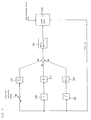
- Fig. 5 shows a first embodiment of the present invention.
- reference numeral 1 denotes a position reference preparation section; 2, a position loop gain; 3, a speed loop gain; 4, an operator; 5, an integrator; 6, a memory; 7, a limiter; 8, a torque reference; 9, an amplifier; 10, a motor for driving each joint portion; 11, a motor position; 12, a differentiator; 13, a motor speed; and 14 to 16, a switch.
- a value stored in the integrator 5 is equal to a force steadily acting on an arm. Therefore, in a control system of a robot arm which makes no rapid movement, a value of the integrator 5 is equal to that obtained by adding a friction force and the gravity. Accordingly, in the case where a transition from the position control to a flexible control is made, the transition can be done with a flexible characteristic and continuity while keeping a gravity balance, by storing this value in the memory 6 and by separately compensating it as a compensation torque of the flexible control.
- control is conducted in a state where the switch 14 is opened and the switch 15 is closed.
- a torque limit is reduced, whereby a flexible characteristic can be brought about for an external force.
- the well known gain may be reduced instead of reducing the torque limit.
- the gravity is compensated by the value stored in the memory.
- the value of the memory 6 having been stored at the time of the switching to the flexible control is set as an initial value of the integrator 5.
- the integration value change is small, so that the transition to the position control is made smoothly.
- the present invention has a feature in that by remaking also the position reference with the present value simultaneously, that is, by closing the switch 16, the transition between both controls can be performed stably without a rapid movement of the robot.
- Fig. 6 shows a positional relation between the robot and a body applying a force on the robot and a control method of the robot.
- a symbol 1 ⁇ denotes an operation state in the position control; a symbol 2 ⁇ , a state where a transition from the position control to the flexible control is made; a symbol 3 ⁇ , a state where the body collides with the robot during the flexible control; a symbol 4 ⁇ , a state where the robot is pushed by the body during the flexible control; a symbol 5 ⁇ , a state where a transition from the flexible control to the position control is made; and a symbol 6 ⁇ , a state where the robot is moved during the position control.
- the speed control system executes an ordinary proportional integration control (state 1 ⁇ ).
- the integration value is stored in the memory so that the integrator is made ineffective, thereby switching the limiter to be a low level state (state 2 ⁇ ).
- the value stored in the memory is set as an initial value of the integration, and, at the same time, a present value of an encoder is replaced with a reference value.
- the continuous transition to the position control can be performed in the state where the body is in contact with the arm.
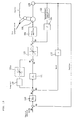
- a second embodiment for compensating the gravity by a computation actively is shown in Fig. 7.
- reference numeral 17 denotes a gravity computation section
- a reference numeral 18 denotes a gravity parameter section.
- the gravity is previously obtained by measurements, and it is computed from the gravity parameter stored in the gravity parameter section 18 (a link mass of the robot and a position of a center of gravity) and the measurement value of the present joint angle of the robot arm, by means of the gravity computation section 17.
- the switch 14 is opened and the switch 15 is closed, thereby transition from the integration compensation to the compensation of the gravity computation value is made.
- the compensation value is fixed.
- the compensation value changes according to the present joint angle of the robot arm so that accuracy is increased.
- the gravity computation value at that time is set as an initial value of the integrator 5.
- the position reference value is remade by the present value by closing the switch 16 similar to the case of the embodiment No. 1 so that the transition to the position control is made smoothly.
- the embodiment No. 3 concerns means for computing a very small movement relation between the joint coordinate system and the operation coordinate system, from the measurement information of the joint angle of the robot, and for obtaining the joint torque limitation value from the force limitation setting value of the operation coordinates.
- Fig. 8 shows a circuit constitution illustrating one concept of an operation in the embodiment No. 3 of the present invention.
- Fig. 9 shows a circuit constitution illustrating another concept in the embodiment No. 3 of the present invention.
- reference numeral 100 denotes a first axis control system; 200, a second axis control system; 300, a third axis control system; n00, a n-th axis control system; 101a, a torque reference; 101b, a position reference; 102, a torque limiter; 103, an amended torque reference; 104, a servo amplifier (torque control); 105, a servo motor; 106, a position detector; 107, operation coordinate force/torque limitation setting means; and 108, computation means for Jacobian's transposed matrix.
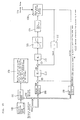
- Fig. 10 is a block diagram illustrating a concrete circuit constitution.
- reference numeral 110 denotes a position control gain [Kp] circuit; 111, a speed control gain [Kv] circuit; 116, a torque limiter; 117, a gravity compensator; 118, a torque conversion constant circuit; 119, a robot (J: an inertia, s: a Laplacian, and D: a dynamic friction coefficient ); and 120, an integration circuit which shows a speed and a speed relation.
- Fig. 10 in this embodiment No. 3 shows a control block diagram when the flexible control system is applied to the conventional control system (the prior art No.1 of Fig. 1).
- a proportional integration control is usually performed, and the force such as the gravity constantly acting on the robot shall be compensated by a static force compensation element.
- the movement by a force acting from the outside has no tendency to occur by operations of the position control loop and the speed control loop. This is because the deviation from the reference value is multiplied by the force applied from the outside by a large gain which is set to be large, thereby generating a motor torque.
- a limitation to the generation torque is made at the stage of the torque reference, whereby the robot can operate flexibly for the force acting from the outside. Specifically, when a torque larger than that limited is applied from the outside, the joint of the robot will begin to move. Moreover, the limitation value of the torque set in this stage is the limitation value of the torque at the joint coordinate system. Therefore, the limitation to the force at the operation position on the top changes based on the posture of the robot.
- the present state of the robot is detected, the correspondence relation between the very small displacements of the joint coordinate system generally called Jacobean and the operation coordinate system is obtained, thereby computing the transposed matrix.
- Jacobean the correspondence relation between the very small displacements of the joint coordinate system generally called Jacobean and the operation coordinate system is obtained, thereby computing the transposed matrix.
- the Jacobian's transposed computation formula and the like in the robot of 6 degrees of freedom is expressed by the (1) to (4) formulas shown by the following equations 1.
- J T denotes a Jacobian's transposed matrix (correspondence relation of a very small displacement between an operation coordinate system and a joint coordinate system); 0 S 1 , a rotation direction vector of first joint coordinates (using a base coordinate system as a reference); 0 P 1 , a first joint position vector (using base coordinates as a reference); ⁇ , a vector product; and r, a tip effect device.
- F lim [Fx, Fy, Fz, ⁇ x , ⁇ y , ⁇ z ] T
- F lim denotes a force and torque limitation vector
- F a force in the operation coordinate system
- ⁇ a torque around the operation coordinate system
- a limitation value in the joint control system is expressed by the following formula (3).
- ⁇ lim [ ⁇ 1 , ⁇ 2 , ⁇ 3 , ⁇ 4 , ⁇ 5 , ⁇ 6 ] T
- ⁇ lim denotes a torque limitation vector of a joint angle
- ⁇ i denotes a torque of the joint coordinate system in an i-th axis (i: an arbitrary positive integer).
- the formula (1) is a value changed by the posture of the robot, and it may change rapidly near a particular point.
- the values of elements change slowly compared to a sampling speed of a CPU which performs a computation for the servo. Therefore, it is possible to suppress a computation load of the formula (1) to be small, and to perform a real time computation accompanied with the posture change of the robot.
- the flexibility in the operation coordinate system is determined only by the limitation value of the formula (2). Specifically, the flexibility can be controlled by determining two variables of plus and minus for the one degree of freedom. Moreover, the force and torque exerted by the robot are never in proportion to the displacement, so that the robot can changes flexibly in case where strokes of machinery acting from the outside is large.
- the embodiment No. 4 of the present invention concerns a system in which an acceleration control loop is added to the conventional flexible control system.
- the flexible control system as the embodiment No. 4 is a flexible control system in which an acceleration control loop is added to the prior art No. 2 shown in Fig. 2 or the prior art No. 4 shown in Fig. 3.
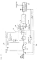
- Fig. 11 is a block diagram showing a summarized circuit constitution in the first means in the embodiment No. 4.
- reference numeral 20 denotes a flexible control system (position/speed control system); 114, an external force; 119a, a robot; 120 and 120a, an integration circuit; 122, an acceleration detection (computation) circuit; 124, a rotation acceleration feedback gain [J'] circuit; 125, a speed detection (computation) circuit; and 126, a position detection circuit.
- the first means comprises means which is capable of changing a position control gain and a speed control gain in a control system of the motor, and feedback control means which limits the output of the integrator during the proportional integration control in the speed control loop and adds the acceleration of the motor multiplied by a constant to a torque reference located at rear stage of the speed control gain multiplier, and output therefrom is used as a torque reference.
- the second means in the control system of the motor constituting the control loop similar to the first means, provided is means which controls the torque reference at the rear stage of the speed controller to a constant value, and provided is feedback control means which multiplies the acceleration of the motor by a constant. The output therefrom is used as a new torque reference.
- reference numeral 115 denotes a differentiater [speed detection means]; 121 and 121a; a torque limiter; 127, an acceleration detector; and 128, an encoder.
- the acceleration can be detected directly by the detector or can be obtained by a difference of the position detector such as an encoder.
- the gravity torque is computed by a computation using parameters such as the mass and the position of a center of gravity of the robot, and added to the torque reference to be output to the amplifier, whereby the gravity torque is compensated.
- Figs. 12 and 13 illustrate concrete embodiment of a second method.
- Fig. 12 shows a case where the rotation acceleration detector of the motor shaft is used as detection means for the acceleration and Fig. 13 shows means for computing the acceleration from the position detector by a computation.
- the robot is applied to the first axis of the scalar type robot operating in a horizontal direction of two degrees of freedom. It should be noted that the same control system can be constituted for the second axis.
- an apparent inertia is reduced more than the inherent inertia by an external force. It should be noted that although delays of the acceleration detection section and the amplification section shall be ignored, a little delay has no great effect on the inertia variation.
- the movement of the second axis changes the inertia viewed from the first axis.
- the value of the real inertia J of the first axis will change, and the reduction quantity of the inertial by the control will be equal to the value determined by the feedback gain of the acceleration, so that a suitable value is determined considering the inertia variation of the movable range of the robot.
- the inertia J' will be determined so that J-J' has no negative value and the loop gain of the speed control loop makes as little variation as possible.
- J' is changed in accordance with the movement of the robot, whereby the apparent inertia can keep the constant value.
- the apparent inertia in case of an external force can be controlled to be small, thereby greatly increasing the flexibility compared to the case of the conventional flexibility control.
- the fact that the apparent inertia can be controlled to be small implies that the action force is made small when the robot would collide with a body around it. For this reason, the safety at the time of robot control can be enhanced.
- control system since the structure of the control system is not fundamentally different from the conventional position/speed control system, it is not necessary to modify the structure of the control system when the transitions from the flexibility control system to the position control system and from the position control system to the flexible control system are conducted.
- control quantity is changed continuously even when the transition of the control system is conducted, whereby the movement of the robot arm is not rapid and discontinuous.
- a detection method of the acceleration will be described.
- a rotation acceleration sensor directly connected to the motor is mentioned as a direct detection method as shown in Fig. 12.
- the example in which the robot of the scalar type moving in the horizontal direction is employed.
- the component in the gravity is compensated by a computation as shown in Fig. 11 and the friction is compensated by detecting the speed, whereby the flexible control system can be constituted.
- This embodiment No. 5 concerns means which monitors a deviation of the position in the flexible control, and is capable of performing an emergency stop for the robot, of outputting information to an exterior instrument, of avoiding a danger based on an operation schedule change, and of monitoring an external force.
- Fig. 14 is a block diagram illustrating a circuit diagram which shows a portion of one axis of the control system of the motor or one direction of the operation coordinate system thereof.
- reference numeral 129 denotes a position deviation
- 130 an operation coordinate system setting value
- 131 comparison means
- 132 means for performing a brake circuit, an external output and an operation schedule judgment.
- Kp and Kv that are a position control gain and a speed control gain shall be reduced or the torque limitation shall be executed.
- the robot makes a posture change in accordance with the force from the load side on the robot. This implies that the robot assumes the posture which is deviated from a position reference of the control system. Therefore, the deviation quantity can be obtained from the deviation between each of the servo motor angles and the reference value.
- the judgment whether a safe operation is being performed is conducted.
- the operation state is not judged to be safe, and any of the following processings are executed.
- the processings are different based on the kinds of operations.
- the following processings are conducted. Specifically, an emergency stop of the robot is conducted, a signal is sent to an external instrument using an input/output contact of the robot (the external instrument is stopped), and condition branching of robot software is performed depending information of the deviation.
- the transition to the normal operation is made when no problem occurs.
- the following processings are conducted in accordance with the external force. Specifically, the force acting on the top of the robot is estimated based on the information of the deviation, and the selection of the body held is performed, and the operation pattern of the robot is changed by the body held.
- FIG. 15 One example of a circuit constitution of a control system which is applied to a robot of multi-degrees of freedom to monitor the deviation of a plurality of coordinates in the operation coordinate system is shown in Fig. 15.
- reference numeral 133 denotes a reverse conversion circuit
- 134 information concerning angles or positions from other axes
- Fig. 15 illustrating another example of the embodiment No. 5 of the present invention constitutes a servo system of an operation coordinate system, and the method to obtain the deviation can be constituted most simply.
- a constitution of an industrial robot which utilizes a joint position servo system used therein most generally is shown in Fig. 15.
- the operation coordinate position reference is usually taken on the Cartesian coordinate system based on the base of the robot, and some deviations of the parallel quantity and the posture quantity are compared with the setting value.
- Fig. 16 shows an example when the operation schedule is changed by the software.
- step 1 After the operation is performed in the position control [step 1], the transition to the flexible control is made [steps 2 and 3], and the servo deviation during the flexible control is monitored [step 4].
- step 5 When the operation is performed normally [step 5], specifically, when an excessive deviation is not produced [step 5], the process advances to the scheduled operation [steps 6 and 7].
- the embodiment No. 6 concerns means for detecting an abnormal state such as contacting and nipping of the robot from the control state quantity, in the flexible control of the robot, changing and lowering the control gain and the torque limitation value to facilitate the escape by a human power, thereby compensating the gravity and the friction.
- Fig. 17 is a block diagram showing a fundamental constitution in the embodiment No. 6 of the present invention.
- reference numeral 11 denotes a position detection value; 20, a flexible control system (position/speed control loop); 21, a control state quantity; 30, state judgment means; 31, a flexibility setting value; 117a, a gravity compensation value; and 117b, a friction compensation value.
- Fig. 18 shows an apparatus using means for changing a position control gain and a speed control gain in the flexible control system.
- Fig. 19 shows a system using means for controlling a torque reference as the flexible control.
- the torque reference (generation torque) of the motor in the flexible control system 20 is computed based on the position detection value and the speed detection value 11 via the differentiator 115.
- reference numeral 22a denotes a flexibility setter; 136, a gravity compensator; and 137, a friction compensator.
- the minimum position control gain setting value and a minimum speed control gain setting value are computed in the flexibility setter 22a, which are necessary to normally operate the arm of the robot, thereby setting them to a variable position control gain 111a and a variable speed control gain 111a.
- the torque reference output from the flexible control system can be made smaller.
- the torque reference after being subjected to the adding processing is amplified by the servo amplifier 104, thereby driving the robot 105.
- the differentiation value of the position deviation, the speed detection value, and the speed deviation that are the control state quantities within the flexible control system 20 are continuously monitored by the flexiblity setter 22a.
- the position control gain setting value and the speed control gain setting value are made minimum or zero, thereby setting them to the variable position control gain 111a and the variable speed control gain 111b.
- the external force acts on the robot 105 so that the robot 105 starts to change its posture from the position reference.
- the position deviation increases [step A]
- the speed detection value reduces [step B]
- a sign of the differentiation value (acceleration) of the speed deviation becomes negative [step C]
- the position control gain setting value and the speed control gain setting value are made minimum or zero so as to reduce the flexibility of the flexible control system, thereby setting them to the variable position control gain 111a and the variable speed control gain 111a.
- the torque reference of the motor from the flexible control system becomes minimum or zero, and the robot becomes stationary keeping the posture at the time when the judgment for the abnormal state is made.
- adding the gravity torque and the friction torque to the torque reference whereby the robot 105 never falls down from gravity, and the operator can operate the robot 105 by human power after the robot becomes stationary.
- the second embodiment No. 2 concerns means which comprises a fundamental conception of the flexible control of the robot facing the prior art No. 2 [Japanese Patent Application Laid Open No. 6-332538], the embodiment No. 4 is applicable to the embodiment No. 3 and the prior art No. 2, the embodiment No. 5 is applicable to the second embodiments No. 2 to No. 4, and the embodiment No. 6 is applicable to the embodiments No. 3 to No. 5 and the prior art No. 2.
- the present invention exhibits effects making the flexible control in the operation coordinate system possible with simple coordinate conversion using the information of the position of the joint angle.
- the two variables of positive and negative can be set with one degree of freedom. Because of the simplicity of the conversion equation itself, the computation load is small, and the computation of the operation coordinate system can be performed in real time fashion.
- the stroke can be set to be large.
- control system of the present invention keeps the fundamental constitution of the conventional one, the transition between the position control and the flexible control will be performed smoothly.
- the robot of the present invention exhibits characteristics possessed by no conventional robot.
- the robot can be moved easily by a force from machinery or by hand.
- the robot never applies a large force to the body.
- the state change of the robot operation is judged from the control state quantity during the flexible control, and the flexibility of the flexible control system is changed. Therefore, even when the operator is caught, the robot stops immediately, and the force generated by the motor disappears. Thus, the robot secures the safety of the operator and the robot.
Abstract
Description
wherein when the transition from the position control to the flexible control is made, an integration operation of the speed control system is stopped, an integration value of the speed control system is subsequently stored in a memory and, at the same time, and the integration value is added to a torque reference or a gravity compensation value computed based on a joint angle of a robot arm, a link mass of the robot and the center of gravity thereof is added to the torque reference.
since the position reference in the state 1) is the value before the force acts on the robot, the robot approaches to the position where the robot exists before the external force acts on it and stops there, by the deviation from the present value. However, the robot is in a rest state with a considerable deviation due to the friction force in an ordinary control state. Therefore, by regenerating the present value of the encoder as the reference value, the smooth transition to the position control can be performed without the rapid movement of the arm.

Also by using
Claims (23)
- A control apparatus of a robot comprising:means for switching between a position control and a flexible control during an operation of the robot;
wherein when a transition from the position control to the flexible control is made, an integration operation of a speed control loop is stopped, an integration value of the speed control loop is subsequently stored in a memory and, at the same time, the integration value of the speed control loop is added to a torque reference, or a gravity compensation value computed based on a joint angle of a robot arm, a link mass of the robot and a center of gravity thereof is added to the torque reference. - The control apparatus of a robot according to claim 1, wherein in case of an operation of the robot to hold a workpiece, a mass of the workpiece is added to said gravity compensation value.
- A control apparatus of a robot comprising:means for switching between a position control and a flexible control during an operation of the robot;
wherein when the control is restored to the position control from the flexible control, a present position is handled as an instruction position. - The control apparatus of a robot which comprises means for switching between the position control and the flexible control during the operation of the robot according to claim 2, wherein when the control is restored from the flexible control to the position control, either a gravity compensation value computed based on an actual joint angle of a robot arm, a link mass of the robot and a position of a center of gravity thereof, or an integration value of the speed control loop stored in said memory is set as a new integration value of said speed control loop.
- The control apparatus of a robot according to claim 1, wherein the switching between said position control and said flexible control is performed by limiting an output value of the speed control loop, that is, a torque reference value.
- The control apparatus of a robot according to claim 2, wherein the switching between said position control and said flexible control is performed by limiting an output value of the speed control loop, that is, a torque reference value.
- The control apparatus of a robot according to claim 3, wherein the switching between said position control and said flexible control is performed by limiting an output value of the speed control loop, that is, a torque reference value.
- A flexible control apparatus of a robot comprising:means for controlling a torque of a servo motor which drives a joint portion of the robot;means for measuring a joint angle of said joint portion;means for computing a very small displacement relation between coordinate systems, based on information of said joint angle obtained by said measuring;means for converting either a force set in an operation coordinate system or a limitation value of the torque to a joint torque limitation value by using said very small displacement relation ; andmeans for limiting an output torque of the robot using said joint torque limitation value.
- The flexible control apparatus of a robot according to claim 8, wherein by using a reference value of said joint angle of the control system of the servo motor which drives the joint portion of the robot, said very small correspondence relation between said operation coordinate system and a joint coordinate system is obtained.
- A flexible control apparatus of a robot which comprises a control system of a servo motor to drive a joint portion of the robot having a position control loop and a speed control loop, comprising:means which is capable of varying position and speed control gains;means for limiting an integration value at an integrator in said speed control loop;means for obtaining a rotation acceleration of said servo motor either by detecting or by computing; andfeedback control means for multiplying the acceleration of said servo motor by a constant at a rear stage of speed control gain multiplication.
- A flexible control apparatus of a robot which comprises a control system of a servo motor to drive a joint portion of the robot having a position control loop and a speed control loop, comprising:means for limiting an integration value at an integrator in said speed control loop;a torque limiter which limits a torque reference that is a result obtained by adding the output of said integrator and a proportional control;means for obtaining a rotation acceleration of said motor either by detecting or by computing; andfeedback control means for multiplying an acceleration of said servo motor by a constant at a rear stage of said torque limiter.
- The flexible control apparatus of a robot according to claim 10, further comprising:means for compensating either a gravity or a friction torque at a rear stage of adding means for adding a speed controller and an integration control.
- The flexible control apparatus of a robot according to claim 11, further comprising:means for compensating either a gravity or a friction torque at a rear stage of adding means for adding a speed controller and an integration control.
- A flexible control apparatus of a robot which comprises a control system of a servo motor of the robot having a position control loop and a speed control loop, comprising:means for comparing a difference between a target angle of a position and a present angle of a servo motor with a setting value; andmeans for stopping a movement of said servo motor based on a comparing result.
- A flexible control apparatus of a robot which comprises a control system of a servo motor of the robot having a position control loop and a speed control loop, comprising:means for comparing a difference between a target angle of a position and a present angle of a servo motor with a setting value; andmeans for outputting a comparing result from a servo instrument to an external instrument.
- A flexible control apparatus of a robot which comprises a control system of a servo motor of the robot having a position control loop and a speed control loop, comprising:means for comparing a difference between a target angle of a position and a present angle of a servo motor with a setting value; andmeans for changing a processing of a servo control based on a comparison result.
- A flexible control apparatus of a robot which comprises a control system of a servo motor of the robot having a plurality of position
control loops and speed control loops, comprising:means for comparing a setting value with a difference between a target value in an operation coordinate system and a present value in an operation coordinate system obtained from a present value of said servo motor; andmeans for stopping a movement of said servo motor based on a comparing result. - A flexible control apparatus of a robot which comprises a control system of a servo motor of a robot having a plurality of position control loops and speed control loops, comprising:means for comparing a setting value with a difference between a target value in an operation coordinate system and a present value in an operation coordinate system obtained from a present value of said servo motor; andmeans for outputting a comparison result to an external instrument from a servo apparatus.
- A flexible control apparatus of a robot which comprises a control system of a servo motor of a robot having a plurality of position control loops and speed control loops, comprising:means for comparing a setting value with a difference between a target value in an operation coordinate system and a present value in an operation coordinate system obtained from a present value of said servo motor; andmeans for changing a processing of a servo control based on a comparison result.
- A flexible control apparatus of a robot which comprises a control
system of a servo motor to drive a joint portion of the robot having a position control loop and a speed control loop, comprising:means for changing a position control gain and a speed control gain; andmeans for converting said position control gain and said speed control gain to other states based on reference information concerning a position, a speed and a direction, detection information, and a computation result using said information. - A flexible control apparatus of a robot which comprises a control system of a servo motor to drive a joint portion of the robot having a position control loop and a speed control loop, comprising:means for limiting a torque reference that is an addition result of outputs of a proportional control and an integrator; andmeans for changing the means for limiting said torque reference based on instruction information concerning a position, a speed and a direction, detection information, and a computing result using said information.
- A flexible control apparatus of a robot according to claim 20, further comprising:means for compensating either a gravity or a friction torque after adding a proportional control and an integration control in said speed control loop.
- A flexible control apparatus of a robot according to claim 21, further comprising:means for compensating either a gravity or a friction torque after adding a proportional control and an integration control in said speed control loop.
Priority Applications (1)
| Application Number | Priority Date | Filing Date | Title |
|---|---|---|---|
| EP20030029866 EP1418026A1 (en) | 1995-09-11 | 1996-09-10 | Control apparatus for robot |
Applications Claiming Priority (5)
| Application Number | Priority Date | Filing Date | Title |
|---|---|---|---|
| JP25923195A JP3460761B2 (en) | 1995-09-11 | 1995-09-11 | Robot control device |
| JP259231/95 | 1995-09-11 | ||
| JP35057095A JP3286842B2 (en) | 1995-12-23 | 1995-12-23 | Flexible control device for robot |
| JP350570/95 | 1995-12-23 | ||
| PCT/JP1996/002574 WO1997010081A1 (en) | 1995-09-11 | 1996-09-10 | Robot controller |
Related Child Applications (1)
| Application Number | Title | Priority Date | Filing Date |
|---|---|---|---|
| EP20030029866 Division EP1418026A1 (en) | 1995-09-11 | 1996-09-10 | Control apparatus for robot |
Publications (3)
| Publication Number | Publication Date |
|---|---|
| EP0881044A1 true EP0881044A1 (en) | 1998-12-02 |
| EP0881044A4 EP0881044A4 (en) | 2002-05-02 |
| EP0881044B1 EP0881044B1 (en) | 2006-06-07 |
Family
ID=26544033
Family Applications (2)
| Application Number | Title | Priority Date | Filing Date |
|---|---|---|---|
| EP20030029866 Withdrawn EP1418026A1 (en) | 1995-09-11 | 1996-09-10 | Control apparatus for robot |
| EP96929577A Expired - Lifetime EP0881044B1 (en) | 1995-09-11 | 1996-09-10 | Robot controller |
Family Applications Before (1)
| Application Number | Title | Priority Date | Filing Date |
|---|---|---|---|
| EP20030029866 Withdrawn EP1418026A1 (en) | 1995-09-11 | 1996-09-10 | Control apparatus for robot |
Country Status (6)
| Country | Link |
|---|---|
| US (1) | US5994864A (en) |
| EP (2) | EP1418026A1 (en) |
| KR (1) | KR100439466B1 (en) |
| CN (2) | CN1067001C (en) |
| DE (1) | DE69636230T2 (en) |
| WO (1) | WO1997010081A1 (en) |
Cited By (12)
| Publication number | Priority date | Publication date | Assignee | Title |
|---|---|---|---|---|
| DE10342471A1 (en) * | 2003-09-15 | 2005-04-14 | Dürr Systems GmbH | Control device for a multi-axis robot |
| EP1750641A2 (en) * | 2004-04-13 | 2007-02-14 | HONDA MOTOR CO., Ltd. | Gravity compensation control system and method using multiple feasibility parameters |
| EP1878542A1 (en) * | 2006-07-07 | 2008-01-16 | Abb Research Ltd. | A control system and a method for controlling one or several industrial robots |
| EP1854584A3 (en) * | 1999-03-16 | 2008-11-05 | National Optronics, Inc. | Tracer, clamp, and object engager for lens mount of an eyeglass frame. |
| EP1422128A3 (en) * | 2002-09-23 | 2008-12-17 | Honda Giken Kogyo Kabushiki Kaisha | Gravity compensation method in a human assist system and a human assist system with gravity compensation control |
| DE102010004474A1 (en) * | 2010-01-13 | 2011-07-14 | KUKA Laboratories GmbH, 86165 | Control for a manipulator |
| EP2380710A1 (en) * | 2003-07-29 | 2011-10-26 | Panasonic Corporation | Robot arm control method and control device |
| CN102837314A (en) * | 2011-06-24 | 2012-12-26 | 镇江华扬信息科技有限公司 | Force/position mixed control method of open type robot controller |
| EP2361736A3 (en) * | 2010-02-23 | 2017-11-29 | Canon Kabushiki Kaisha | Rotary drive device |
| EP2492062B1 (en) | 2011-02-02 | 2018-10-31 | KUKA Deutschland GmbH | Industrial robot |
| EP3280569A4 (en) * | 2015-04-07 | 2019-01-23 | Mobile Tool Management, Inc. | System and method for adjusting end-effector actuation based on relative position with respect to gravitational force |
| EP3439168A4 (en) * | 2016-03-29 | 2019-03-13 | Panasonic Intellectual Property Management Co., Ltd. | Motor control device |
Families Citing this family (138)
| Publication number | Priority date | Publication date | Assignee | Title |
|---|---|---|---|---|
| JPH11277468A (en) * | 1998-03-30 | 1999-10-12 | Denso Corp | Control device for robot |
| US6278906B1 (en) * | 1999-01-29 | 2001-08-21 | Georgia Tech Research Corporation | Uncalibrated dynamic mechanical system controller |
| SG84531A1 (en) * | 1999-05-20 | 2001-11-20 | Univ Singapore | Disturbance attenuation in a precision servomechanism by a frequency-separated acceleration soft sensor |
| EP1184766B1 (en) * | 1999-06-04 | 2003-11-19 | Kabushiki Kaisha Yaskawa Denki Seisakusho | Position controller for motor |
| JP3473834B2 (en) * | 1999-11-29 | 2003-12-08 | 株式会社安川電機 | Robot control device |
| KR100367486B1 (en) * | 2001-02-26 | 2003-01-10 | 삼성테크윈 주식회사 | Method for controlling home position of servo-moter |
| JP4628602B2 (en) * | 2001-04-05 | 2011-02-09 | ナブテスコ株式会社 | Robot arm |
| KR100805242B1 (en) * | 2001-07-06 | 2008-02-21 | 삼성전자주식회사 | Controlling system and method for servomotor |
| US7068002B2 (en) * | 2002-04-05 | 2006-06-27 | Mitsubishi Denki Kabushiki Kaisha | Motor control device |
| JP4043996B2 (en) * | 2003-01-20 | 2008-02-06 | ファナック株式会社 | Servo motor drive control device |
| JP4367058B2 (en) * | 2003-09-04 | 2009-11-18 | 株式会社安川電機 | Motor control device |
| JP4536349B2 (en) * | 2003-09-22 | 2010-09-01 | パナソニック株式会社 | Multi-degree-of-freedom robot arm control apparatus and control method using elastic actuator |
| US8000837B2 (en) | 2004-10-05 | 2011-08-16 | J&L Group International, Llc | Programmable load forming system, components thereof, and methods of use |
| JP4281696B2 (en) * | 2005-03-14 | 2009-06-17 | セイコーエプソン株式会社 | Acceleration / deceleration control method and apparatus, and acceleration / deceleration control method program |
| US7211979B2 (en) * | 2005-04-13 | 2007-05-01 | The Broad Of Trustees Of The Leland Stanford Junior University | Torque-position transformer for task control of position controlled robots |
| JP4202365B2 (en) * | 2006-03-07 | 2008-12-24 | ファナック株式会社 | Force control device |
| US7453228B2 (en) * | 2006-04-07 | 2008-11-18 | Asml Netherlands B.V. | Method for controlling a positioning device, positioning device, and lithographic apparatus provided with a positioning device |
| US8849457B2 (en) * | 2006-07-17 | 2014-09-30 | Raytheon Company | Contact displacement actuator system |
| JP4267027B2 (en) * | 2006-12-07 | 2009-05-27 | ファナック株式会社 | Robot controller |
| JP4836872B2 (en) * | 2007-05-31 | 2011-12-14 | 株式会社東芝 | Control device, control method, program, and robot |
| CN102248537B (en) * | 2007-06-27 | 2013-12-04 | 松下电器产业株式会社 | Apparatus and method for controlling robot arm, and robot |
| WO2009027673A1 (en) | 2007-08-28 | 2009-03-05 | The University Of Surrey | Inverse kinematics |
| WO2009088828A1 (en) * | 2007-12-31 | 2009-07-16 | Abb Research Ltd. | Method and apparatus using a force sensor to provide load compensation for a robot |
| JP5202136B2 (en) * | 2008-07-02 | 2013-06-05 | 株式会社日立ハイテクノロジーズ | Charged particle beam equipment |
| US8239063B2 (en) * | 2008-07-29 | 2012-08-07 | Fanuc Robotics America, Inc. | Servo motor monitoring and hood/deck exchange to enhance the interior coating process |
| KR101474765B1 (en) * | 2008-12-05 | 2014-12-22 | 삼성전자 주식회사 | Robot arm and control method thereof |
| CN102483625B (en) | 2009-08-14 | 2015-09-09 | Abb技术有限公司 | The method of industrial robot and adjustment robot program |
| KR20110017500A (en) * | 2009-08-14 | 2011-02-22 | 삼성전자주식회사 | Control device for legged mobile robot and control method thereof |
| DE112010005024B4 (en) * | 2009-12-28 | 2016-05-25 | Honda Motor Co., Ltd. | Robot controller |
| JP5689704B2 (en) * | 2010-08-08 | 2015-03-25 | 日本電産サンキョー株式会社 | Motor control device and motor control method |
| US8650965B2 (en) * | 2010-08-31 | 2014-02-18 | Kabushiki Kaisha Yaskawa Denki | Robot, robot system, robot control device, and state determining method |
| US8483877B2 (en) | 2010-09-03 | 2013-07-09 | GM Global Technology Operations LLC | Workspace safe operation of a force- or impedance-controlled robot |
| KR101871212B1 (en) * | 2010-11-26 | 2018-06-27 | 로제 가부시키가이샤 | Robot control device and control method |
| WO2012077335A1 (en) * | 2010-12-08 | 2012-06-14 | パナソニック株式会社 | Control device and control method for robot, robot, and control program |
| US9314921B2 (en) | 2011-03-17 | 2016-04-19 | Sarcos Lc | Robotic lift device with human interface operation |
| US9789603B2 (en) | 2011-04-29 | 2017-10-17 | Sarcos Lc | Teleoperated robotic system |
| US8942846B2 (en) | 2011-04-29 | 2015-01-27 | Raytheon Company | System and method for controlling a teleoperated robotic agile lift system |
| US8892258B2 (en) | 2011-04-29 | 2014-11-18 | Raytheon Company | Variable strength magnetic end effector for lift systems |
| US8977388B2 (en) | 2011-04-29 | 2015-03-10 | Sarcos Lc | Platform perturbation compensation |
| US9566710B2 (en) | 2011-06-02 | 2017-02-14 | Brain Corporation | Apparatus and methods for operating robotic devices using selective state space training |
| JP5907678B2 (en) * | 2011-07-20 | 2016-04-26 | オリンパス株式会社 | Medical operating mechanism and manipulator |
| JP5962659B2 (en) * | 2011-09-13 | 2016-08-03 | 株式会社安川電機 | Self-propelled robot and self-propelled cart |
| JP5399593B2 (en) * | 2011-11-10 | 2014-01-29 | パナソニック株式会社 | ROBOT, ROBOT CONTROL DEVICE, CONTROL METHOD, AND CONTROL PROGRAM |
| KR101292550B1 (en) * | 2011-12-16 | 2013-08-12 | 한국과학기술연구원 | Balance control device and method of ball-on-plate system |
| CN102554930A (en) * | 2012-01-11 | 2012-07-11 | 成都市新筑路桥机械股份有限公司 | Mechanical arm control system and control method |
| US20130197672A1 (en) * | 2012-01-26 | 2013-08-01 | Intuitive Surgical Operations, Inc. | Pass-Through Controller for Cascaded Proportional-Integral-Derivative Control Loops |
| US9616580B2 (en) | 2012-05-14 | 2017-04-11 | Sarcos Lc | End effector for a robotic arm |
| CN104379308B (en) * | 2012-06-29 | 2016-05-18 | 三菱电机株式会社 | Robot controller and robot control method |
| JP6312264B2 (en) * | 2012-09-17 | 2018-04-18 | リシンク ロボティクス インコーポレイテッド | Constraints on robot manipulators with redundant degrees of freedom |
| KR102023910B1 (en) | 2012-11-23 | 2019-09-23 | 삼성전자주식회사 | Robot and friction compensation method for the robot |
| CN103056872B (en) * | 2013-01-15 | 2014-10-29 | 西北工业大学 | Space manipulator teleoperation instruction safety detection and correction method |
| EP2952414B1 (en) * | 2013-01-29 | 2018-03-07 | NSK Ltd. | Electric power steering device |
| US9764468B2 (en) | 2013-03-15 | 2017-09-19 | Brain Corporation | Adaptive predictor apparatus and methods |
| JP5741618B2 (en) * | 2013-03-19 | 2015-07-01 | 株式会社安川電機 | Workpiece assembly apparatus and assembly method |
| JP5616478B1 (en) * | 2013-04-18 | 2014-10-29 | ファナック株式会社 | Robot system equipped with a robot for transporting workpieces |
| US9242372B2 (en) | 2013-05-31 | 2016-01-26 | Brain Corporation | Adaptive robotic interface apparatus and methods |
| US9314924B1 (en) | 2013-06-14 | 2016-04-19 | Brain Corporation | Predictive robotic controller apparatus and methods |
| US9384443B2 (en) | 2013-06-14 | 2016-07-05 | Brain Corporation | Robotic training apparatus and methods |
| US9792546B2 (en) | 2013-06-14 | 2017-10-17 | Brain Corporation | Hierarchical robotic controller apparatus and methods |
| US9579789B2 (en) | 2013-09-27 | 2017-02-28 | Brain Corporation | Apparatus and methods for training of robotic control arbitration |
| US9597797B2 (en) | 2013-11-01 | 2017-03-21 | Brain Corporation | Apparatus and methods for haptic training of robots |
| US9463571B2 (en) | 2013-11-01 | 2016-10-11 | Brian Corporation | Apparatus and methods for online training of robots |
| JP5746308B2 (en) * | 2013-11-26 | 2015-07-08 | ファナック株式会社 | Servo control device with a function to reduce the brake fall amount |
| JP5813746B2 (en) * | 2013-12-26 | 2015-11-17 | 川崎重工業株式会社 | Robot control system |
| US9358685B2 (en) * | 2014-02-03 | 2016-06-07 | Brain Corporation | Apparatus and methods for control of robot actions based on corrective user inputs |
| FR3019279B1 (en) | 2014-03-28 | 2018-06-22 | Safran Electronics & Defense | OPTRONIC ARMY TURTLE |
| US9346167B2 (en) | 2014-04-29 | 2016-05-24 | Brain Corporation | Trainable convolutional network apparatus and methods for operating a robotic vehicle |
| JP5845311B2 (en) | 2014-04-30 | 2016-01-20 | ファナック株式会社 | Control device for flexible control of robots |
| US10766133B2 (en) | 2014-05-06 | 2020-09-08 | Sarcos Lc | Legged robotic device utilizing modifiable linkage mechanism |
| JP2016064479A (en) * | 2014-09-25 | 2016-04-28 | ファナック株式会社 | Robot control device |
| US9630318B2 (en) | 2014-10-02 | 2017-04-25 | Brain Corporation | Feature detection apparatus and methods for training of robotic navigation |
| KR20230129615A (en) | 2014-10-27 | 2023-09-08 | 인튜어티브 서지컬 오퍼레이션즈 인코포레이티드 | System and method for instrument disturbance compensation |
| KR20230096131A (en) | 2014-10-27 | 2023-06-29 | 인튜어티브 서지컬 오퍼레이션즈 인코포레이티드 | System and method for integrated surgical table |
| WO2016069661A1 (en) | 2014-10-27 | 2016-05-06 | Intuitive Surgical Operations, Inc. | Medical device with active brake release control |
| KR20240013853A (en) | 2014-10-27 | 2024-01-30 | 인튜어티브 서지컬 오퍼레이션즈 인코포레이티드 | System and method for monitoring control points during reactive motion |
| KR102617042B1 (en) | 2014-10-27 | 2023-12-27 | 인튜어티브 서지컬 오퍼레이션즈 인코포레이티드 | System and method for registering to a surgical table |
| EP3212151B1 (en) | 2014-10-27 | 2020-07-29 | Intuitive Surgical Operations, Inc. | System for integrated surgical table motion |
| JP6774404B2 (en) | 2014-10-27 | 2020-10-21 | インテュイティブ サージカル オペレーションズ, インコーポレイテッド | Systems and methods for integrated operating table icons |
| US9717387B1 (en) | 2015-02-26 | 2017-08-01 | Brain Corporation | Apparatus and methods for programming and training of robotic household appliances |
| US9505132B1 (en) * | 2015-03-30 | 2016-11-29 | X Development Llc | Methods and systems for calibrating a sensor of a robotic device |
| KR102086504B1 (en) * | 2015-05-15 | 2020-03-09 | 인튜어티브 서지컬 오퍼레이션즈 인코포레이티드 | System and method for compensating force or torque limits |
| JP6077592B2 (en) * | 2015-05-29 | 2017-02-08 | ファナック株式会社 | Motor control system and brake abnormality detection method having function of detecting brake abnormality |
| CN106301094A (en) * | 2015-06-05 | 2017-01-04 | 唐山开诚电控设备集团有限公司 | Mine belt conveyor drives motor multi-machine interaction method for controlling power balance |
| DE102015008144B4 (en) | 2015-06-24 | 2024-01-18 | Kuka Roboter Gmbh | Switching a control of a robot to a hand-held operating mode |
| JP6699843B2 (en) * | 2015-07-04 | 2020-05-27 | 学校法人早稲田大学 | Robot arm control system |
| JP6581833B2 (en) * | 2015-07-30 | 2019-09-25 | アズビル株式会社 | Actuator failure detection device, control device and method |
| US10350766B2 (en) * | 2015-09-21 | 2019-07-16 | GM Global Technology Operations LLC | Extended-reach assist device for performing assembly tasks |
| US10471594B2 (en) * | 2015-12-01 | 2019-11-12 | Kindred Systems Inc. | Systems, devices, and methods for the distribution and collection of multimodal data associated with robots |
| DE102017000063B4 (en) * | 2016-01-14 | 2019-10-31 | Fanuc Corporation | Robot device with learning function |
| CN107322591B (en) * | 2016-04-29 | 2020-05-08 | 上银科技股份有限公司 | Movement control method of endoscope driven by mechanical arm |
| US10241514B2 (en) | 2016-05-11 | 2019-03-26 | Brain Corporation | Systems and methods for initializing a robot to autonomously travel a trained route |
| DE102016210060A1 (en) * | 2016-06-08 | 2017-12-14 | Kuka Roboter Gmbh | Method for safely stopping a manipulator |
| US9987752B2 (en) | 2016-06-10 | 2018-06-05 | Brain Corporation | Systems and methods for automatic detection of spills |
| US10282849B2 (en) | 2016-06-17 | 2019-05-07 | Brain Corporation | Systems and methods for predictive/reconstructive visual object tracker |
| US10016896B2 (en) | 2016-06-30 | 2018-07-10 | Brain Corporation | Systems and methods for robotic behavior around moving bodies |
| JP6711536B2 (en) * | 2016-10-28 | 2020-06-17 | アズビル株式会社 | External force detection method |
| US10274325B2 (en) | 2016-11-01 | 2019-04-30 | Brain Corporation | Systems and methods for robotic mapping |
| US10001780B2 (en) | 2016-11-02 | 2018-06-19 | Brain Corporation | Systems and methods for dynamic route planning in autonomous navigation |
| US10919161B2 (en) | 2016-11-11 | 2021-02-16 | Sarcos Corp. | Clutched joint modules for a robotic system |
| US10828767B2 (en) | 2016-11-11 | 2020-11-10 | Sarcos Corp. | Tunable actuator joint modules having energy recovering quasi-passive elastic actuators with internal valve arrangements |
| US10821614B2 (en) | 2016-11-11 | 2020-11-03 | Sarcos Corp. | Clutched joint modules having a quasi-passive elastic actuator for a robotic assembly |
| US10765537B2 (en) | 2016-11-11 | 2020-09-08 | Sarcos Corp. | Tunable actuator joint modules having energy recovering quasi-passive elastic actuators for use within a robotic system |
| US10723018B2 (en) | 2016-11-28 | 2020-07-28 | Brain Corporation | Systems and methods for remote operating and/or monitoring of a robot |
| CN106716282B (en) * | 2016-12-17 | 2019-06-11 | 深圳前海达闼云端智能科技有限公司 | Method, control device and the control equipment that a kind of pair of target is controlled |
| CN106730638B (en) * | 2016-12-21 | 2018-11-02 | 华中科技大学 | The control method of the drive lacking healing robot of motion intention is identified based on reciprocal force |
| US10377040B2 (en) | 2017-02-02 | 2019-08-13 | Brain Corporation | Systems and methods for assisting a robotic apparatus |
| US10852730B2 (en) | 2017-02-08 | 2020-12-01 | Brain Corporation | Systems and methods for robotic mobile platforms |
| US10293485B2 (en) | 2017-03-30 | 2019-05-21 | Brain Corporation | Systems and methods for robotic path planning |
| US10173323B2 (en) | 2017-06-09 | 2019-01-08 | Precise Automation, Inc. | Collaborative robot |
| US10252420B2 (en) * | 2017-06-09 | 2019-04-09 | Precise Automation, Inc. | Collaborative robot |
| CN107443379A (en) * | 2017-08-21 | 2017-12-08 | 北京精密机电控制设备研究所 | A kind of mechanical arm motion control method based on emulation data |
| CN107577168A (en) * | 2017-09-08 | 2018-01-12 | 国机智能技术研究院有限公司 | A kind of robot control system and method |
| US10843330B2 (en) | 2017-12-07 | 2020-11-24 | Sarcos Corp. | Resistance-based joint constraint for a master robotic system |
| US11331809B2 (en) | 2017-12-18 | 2022-05-17 | Sarcos Corp. | Dynamically controlled robotic stiffening element |
| CN108107788B (en) * | 2017-12-26 | 2019-11-05 | 广东美的安川服务机器人有限公司 | The mode switching method and device of recovery exercising robot |
| CN108189036B (en) * | 2018-01-17 | 2021-08-13 | 广州视源电子科技股份有限公司 | Torque control method and device, robot and storage medium |
| CN112368116A (en) * | 2018-06-15 | 2021-02-12 | 优傲机器人公司 | Estimation of payload attached to a robotic arm |
| CN109371557B (en) * | 2018-11-21 | 2024-02-20 | 杭州之山智控技术有限公司 | Flat knitting machine lifting plate control system and method thereof |
| CN109352661B (en) * | 2018-12-11 | 2022-01-18 | 上海辛格林纳新时达电机有限公司 | Control method of robot joint, servo driving device and storable medium |
| CN109773781B (en) * | 2018-12-26 | 2021-05-25 | 南京埃斯顿机器人工程有限公司 | Linear soft floating control method of industrial robot without sensor |
| US11351675B2 (en) | 2018-12-31 | 2022-06-07 | Sarcos Corp. | Robotic end-effector having dynamic stiffening elements for conforming object interaction |
| US10906191B2 (en) | 2018-12-31 | 2021-02-02 | Sarcos Corp. | Hybrid robotic end effector |
| US11241801B2 (en) | 2018-12-31 | 2022-02-08 | Sarcos Corp. | Robotic end effector with dorsally supported actuation mechanism |
| CN109732605B (en) * | 2019-01-21 | 2021-02-26 | 厦门大学 | Robot joint friction torque compensation method and system |
| CN110142762B (en) * | 2019-05-10 | 2022-02-01 | 武汉库柏特科技有限公司 | Robot joint position control method and device and robot |
| JP7283994B2 (en) * | 2019-06-21 | 2023-05-30 | ファナック株式会社 | Robot controller and programming device |
| CN114126811A (en) * | 2019-07-18 | 2022-03-01 | 株式会社安川电机 | Robot system, robot control method, and servo system |
| CN114127659B (en) | 2019-07-18 | 2024-02-27 | 株式会社安川电机 | Control system, control method, and nonvolatile memory device |
| CN110815217B (en) * | 2019-10-29 | 2022-11-04 | 中科新松有限公司 | Robot servo torque control method based on speed control mode |
| CN111416561B (en) * | 2020-03-09 | 2022-05-31 | 埃夫特智能装备股份有限公司 | Improved three-ring control method for motor |
| CN112008718B (en) * | 2020-06-12 | 2022-04-05 | 特斯联科技集团有限公司 | Robot control method, system, storage medium and intelligent robot |
| US11833676B2 (en) | 2020-12-07 | 2023-12-05 | Sarcos Corp. | Combining sensor output data to prevent unsafe operation of an exoskeleton |
| US11794345B2 (en) | 2020-12-31 | 2023-10-24 | Sarcos Corp. | Unified robotic vehicle systems and methods of control |
| CN113961020B (en) * | 2021-12-22 | 2022-04-08 | 普宙科技(深圳)有限公司 | Unmanned aerial vehicle three-dimensional space motion control method and system |
| US11826907B1 (en) | 2022-08-17 | 2023-11-28 | Sarcos Corp. | Robotic joint system with length adapter |
| US11717956B1 (en) | 2022-08-29 | 2023-08-08 | Sarcos Corp. | Robotic joint system with integrated safety |
| US11897132B1 (en) | 2022-11-17 | 2024-02-13 | Sarcos Corp. | Systems and methods for redundant network communication in a robot |
| US11924023B1 (en) | 2022-11-17 | 2024-03-05 | Sarcos Corp. | Systems and methods for redundant network communication in a robot |
Citations (9)
| Publication number | Priority date | Publication date | Assignee | Title |
|---|---|---|---|---|
| US4682089A (en) * | 1984-12-17 | 1987-07-21 | Kabushiki Kaisha Toshiba | Robot control system |
| US4807153A (en) * | 1986-11-20 | 1989-02-21 | Unimation Inc. | Multiaxis digital robot control having a backup velocity monitor and protection system |
| US4868474A (en) * | 1986-11-20 | 1989-09-19 | Westinghouse Electric Corp. | Multiprocessor position/velocity servo control for multiaxis digital robot control system |
| US4893068A (en) * | 1988-11-15 | 1990-01-09 | Hughes Aircraft Company | Digital servo employing switch mode lead/lag integrator |
| US4925312A (en) * | 1988-03-21 | 1990-05-15 | Staubli International Ag | Robot control system having adaptive feedforward torque control for improved accuracy |
| US4985668A (en) * | 1989-09-19 | 1991-01-15 | Kabushiki Kaisha Kobe Seiko Sho | Robot controller |
| US5180956A (en) * | 1990-03-30 | 1993-01-19 | Kabushiki Kaisha Toshiba | Adaptability controller for robots |
| US5430643A (en) * | 1992-03-11 | 1995-07-04 | The United States Of America As Represented By The Administrator Of The National Aeronautics And Space Administration | Configuration control of seven degree of freedom arms |
| EP0661615A1 (en) * | 1993-05-19 | 1995-07-05 | Fanuc Ltd. | Method for controlling servo mechanism flexibly |
Family Cites Families (11)
| Publication number | Priority date | Publication date | Assignee | Title |
|---|---|---|---|---|
| DE1906836C3 (en) * | 1969-02-12 | 1975-01-02 | Siemens Ag, 1000 Berlin Und 8000 Muenchen | Adaptive control device for a control loop |
| JPS57113117A (en) * | 1980-12-30 | 1982-07-14 | Fanuc Ltd | Robot control system |
| JPS58139201A (en) * | 1982-02-12 | 1983-08-18 | Toyota Central Res & Dev Lab Inc | Failure detector for servo system |
| JPH0738070B2 (en) * | 1986-07-25 | 1995-04-26 | 富士写真フイルム株式会社 | Silver halide photographic light-sensitive material |
| JPH06100935B2 (en) * | 1986-10-15 | 1994-12-12 | 日本電信電話株式会社 | Load weight compensation control method for manipulator |
| JPH01230107A (en) * | 1988-03-10 | 1989-09-13 | Fanuc Ltd | Method for detecting collision of body to be driven by servomotor |
| JPH04104315U (en) * | 1991-02-21 | 1992-09-08 | エヌオーケー株式会社 | Compliance control parameter change device |
| GB2256290B (en) * | 1991-05-27 | 1994-07-20 | Honda Motor Co Ltd | Servomotor control system for multi-axes |
| JP2604929B2 (en) * | 1991-12-03 | 1997-04-30 | 山武ハネウエル株式会社 | Robot control device |
| JPH0639760A (en) * | 1992-07-23 | 1994-02-15 | Hitachi Ltd | Control device for robot |
| JP3283650B2 (en) | 1993-07-05 | 2002-05-20 | ファナック株式会社 | Robot controller |
-
1996
- 1996-09-10 KR KR10-1998-0701823A patent/KR100439466B1/en not_active IP Right Cessation
- 1996-09-10 US US09/029,735 patent/US5994864A/en not_active Expired - Lifetime
- 1996-09-10 WO PCT/JP1996/002574 patent/WO1997010081A1/en active IP Right Grant
- 1996-09-10 EP EP20030029866 patent/EP1418026A1/en not_active Withdrawn
- 1996-09-10 DE DE69636230T patent/DE69636230T2/en not_active Expired - Lifetime
- 1996-09-10 EP EP96929577A patent/EP0881044B1/en not_active Expired - Lifetime
- 1996-09-10 CN CN96197955A patent/CN1067001C/en not_active Expired - Lifetime
-
2000
- 2000-02-16 CN CN00102622A patent/CN1131766C/en not_active Expired - Lifetime
Patent Citations (9)
| Publication number | Priority date | Publication date | Assignee | Title |
|---|---|---|---|---|
| US4682089A (en) * | 1984-12-17 | 1987-07-21 | Kabushiki Kaisha Toshiba | Robot control system |
| US4807153A (en) * | 1986-11-20 | 1989-02-21 | Unimation Inc. | Multiaxis digital robot control having a backup velocity monitor and protection system |
| US4868474A (en) * | 1986-11-20 | 1989-09-19 | Westinghouse Electric Corp. | Multiprocessor position/velocity servo control for multiaxis digital robot control system |
| US4925312A (en) * | 1988-03-21 | 1990-05-15 | Staubli International Ag | Robot control system having adaptive feedforward torque control for improved accuracy |
| US4893068A (en) * | 1988-11-15 | 1990-01-09 | Hughes Aircraft Company | Digital servo employing switch mode lead/lag integrator |
| US4985668A (en) * | 1989-09-19 | 1991-01-15 | Kabushiki Kaisha Kobe Seiko Sho | Robot controller |
| US5180956A (en) * | 1990-03-30 | 1993-01-19 | Kabushiki Kaisha Toshiba | Adaptability controller for robots |
| US5430643A (en) * | 1992-03-11 | 1995-07-04 | The United States Of America As Represented By The Administrator Of The National Aeronautics And Space Administration | Configuration control of seven degree of freedom arms |
| EP0661615A1 (en) * | 1993-05-19 | 1995-07-05 | Fanuc Ltd. | Method for controlling servo mechanism flexibly |
Non-Patent Citations (1)
| Title |
|---|
| See also references of WO9710081A1 * |
Cited By (15)
| Publication number | Priority date | Publication date | Assignee | Title |
|---|---|---|---|---|
| EP1854584A3 (en) * | 1999-03-16 | 2008-11-05 | National Optronics, Inc. | Tracer, clamp, and object engager for lens mount of an eyeglass frame. |
| EP1422128A3 (en) * | 2002-09-23 | 2008-12-17 | Honda Giken Kogyo Kabushiki Kaisha | Gravity compensation method in a human assist system and a human assist system with gravity compensation control |
| EP2380710A1 (en) * | 2003-07-29 | 2011-10-26 | Panasonic Corporation | Robot arm control method and control device |
| DE10342471B4 (en) * | 2003-09-15 | 2007-08-16 | Dürr Systems GmbH | Control device for a multi-axis robot |
| DE10342471A1 (en) * | 2003-09-15 | 2005-04-14 | Dürr Systems GmbH | Control device for a multi-axis robot |
| EP1750641A2 (en) * | 2004-04-13 | 2007-02-14 | HONDA MOTOR CO., Ltd. | Gravity compensation control system and method using multiple feasibility parameters |
| EP1750641A4 (en) * | 2004-04-13 | 2010-01-27 | Honda Motor Co Ltd | Gravity compensation control system and method using multiple feasibility parameters |
| EP1878542A1 (en) * | 2006-07-07 | 2008-01-16 | Abb Research Ltd. | A control system and a method for controlling one or several industrial robots |
| DE102010004474A1 (en) * | 2010-01-13 | 2011-07-14 | KUKA Laboratories GmbH, 86165 | Control for a manipulator |
| EP2361736A3 (en) * | 2010-02-23 | 2017-11-29 | Canon Kabushiki Kaisha | Rotary drive device |
| EP2492062B1 (en) | 2011-02-02 | 2018-10-31 | KUKA Deutschland GmbH | Industrial robot |
| CN102837314A (en) * | 2011-06-24 | 2012-12-26 | 镇江华扬信息科技有限公司 | Force/position mixed control method of open type robot controller |
| EP3280569A4 (en) * | 2015-04-07 | 2019-01-23 | Mobile Tool Management, Inc. | System and method for adjusting end-effector actuation based on relative position with respect to gravitational force |
| EP3439168A4 (en) * | 2016-03-29 | 2019-03-13 | Panasonic Intellectual Property Management Co., Ltd. | Motor control device |
| US10644619B2 (en) | 2016-03-29 | 2020-05-05 | Panasonic Intellectual Property Management Co., Ltd. | Motor control device |
Also Published As
| Publication number | Publication date |
|---|---|
| CN1200692A (en) | 1998-12-02 |
| KR100439466B1 (en) | 2004-09-18 |
| EP0881044A4 (en) | 2002-05-02 |
| CN1275470A (en) | 2000-12-06 |
| EP1418026A1 (en) | 2004-05-12 |
| DE69636230D1 (en) | 2006-07-20 |
| CN1131766C (en) | 2003-12-24 |
| KR19990044574A (en) | 1999-06-25 |
| CN1067001C (en) | 2001-06-13 |
| US5994864A (en) | 1999-11-30 |
| EP0881044B1 (en) | 2006-06-07 |
| WO1997010081A1 (en) | 1997-03-20 |
| DE69636230T2 (en) | 2007-04-12 |
Similar Documents
| Publication | Publication Date | Title |
|---|---|---|
| US5994864A (en) | Robot controller | |
| US7212886B2 (en) | Robot control apparatus and method | |
| EP0280324B1 (en) | Nonlinear control unit for a multi-degree-of freedom manipulator | |
| US8335591B2 (en) | Robot apparatus and method of controlling the same | |
| US5049797A (en) | Device and method for control of flexible link robot manipulators | |
| US5056038A (en) | Apparatus for effecting coordinated position/force control for a manipulator | |
| US5627440A (en) | Method of computing drive pattern for suppressing vibration of industrial robot | |
| Murakami et al. | Force sensorless impedance control by disturbance observer | |
| EP0129245A1 (en) | Method and apparatus for controlling a robot | |
| EP1505463B1 (en) | Position control device and position control method for machine tools | |
| EP1023973B1 (en) | Robot control method and device | |
| JP3286842B2 (en) | Flexible control device for robot | |
| JPH07104856A (en) | Vibration control method | |
| JP2604929B2 (en) | Robot control device | |
| JP4055090B2 (en) | Robot control device | |
| JP2619227B2 (en) | Robot control method and device | |
| JP3460761B2 (en) | Robot control device | |
| EP0386791B1 (en) | Apparatus for and method of controlling positioning of movable member | |
| JP4134369B2 (en) | Robot control device | |
| JPH03110606A (en) | Servo controller | |
| Surdilovic | Contact transition stability in the impedance control | |
| JP6711536B2 (en) | External force detection method | |
| JP2000099105A (en) | Control method for load machine | |
| JP7182952B2 (en) | CONTROL METHOD, CONTROL PROGRAM, RECORDING MEDIUM, CONTROL DEVICE, ROBOT SYSTEM, AND PRODUCT MANUFACTURING METHOD | |
| JP2798518B2 (en) | Manipulator control device |
Legal Events
| Date | Code | Title | Description |
|---|---|---|---|
| PUAI | Public reference made under article 153(3) epc to a published international application that has entered the european phase |
Free format text: ORIGINAL CODE: 0009012 |
|
| 17P | Request for examination filed |
Effective date: 19980408 |
|
| AK | Designated contracting states |
Kind code of ref document: A1 Designated state(s): DE FR GB SE |
|
| RIC1 | Information provided on ipc code assigned before grant |
Free format text: 7B 25J 13/00 A, 7B 25J 9/16 B, 7G 05B 19/23 B |
|
| A4 | Supplementary search report drawn up and despatched |
Effective date: 20020314 |
|
| AK | Designated contracting states |
Kind code of ref document: A4 Designated state(s): DE FR GB SE |
|
| 17Q | First examination report despatched |
Effective date: 20030620 |
|
| GRAP | Despatch of communication of intention to grant a patent |
Free format text: ORIGINAL CODE: EPIDOSNIGR1 |
|
| GRAC | Information related to communication of intention to grant a patent modified |
Free format text: ORIGINAL CODE: EPIDOSCIGR1 |
|
| GRAS | Grant fee paid |
Free format text: ORIGINAL CODE: EPIDOSNIGR3 |
|
| GRAA | (expected) grant |
Free format text: ORIGINAL CODE: 0009210 |
|
| AK | Designated contracting states |
Kind code of ref document: B1 Designated state(s): DE FR GB SE |
|
| REG | Reference to a national code |
Ref country code: GB Ref legal event code: FG4D |
|
| REF | Corresponds to: |
Ref document number: 69636230 Country of ref document: DE Date of ref document: 20060720 Kind code of ref document: P |
|
| REG | Reference to a national code |
Ref country code: SE Ref legal event code: TRGR |
|
| ET | Fr: translation filed | ||
| PLBE | No opposition filed within time limit |
Free format text: ORIGINAL CODE: 0009261 |
|
| STAA | Information on the status of an ep patent application or granted ep patent |
Free format text: STATUS: NO OPPOSITION FILED WITHIN TIME LIMIT |
|
| 26N | No opposition filed |
Effective date: 20070308 |
|
| PGFP | Annual fee paid to national office [announced via postgrant information from national office to epo] |
Ref country code: FR Payment date: 20080915 Year of fee payment: 13 |
|
| PGFP | Annual fee paid to national office [announced via postgrant information from national office to epo] |
Ref country code: GB Payment date: 20080910 Year of fee payment: 13 |
|
| GBPC | Gb: european patent ceased through non-payment of renewal fee |
Effective date: 20090910 |
|
| REG | Reference to a national code |
Ref country code: FR Ref legal event code: ST Effective date: 20100531 |
|
| PG25 | Lapsed in a contracting state [announced via postgrant information from national office to epo] |
Ref country code: FR Free format text: LAPSE BECAUSE OF NON-PAYMENT OF DUE FEES Effective date: 20090930 |
|
| PG25 | Lapsed in a contracting state [announced via postgrant information from national office to epo] |
Ref country code: GB Free format text: LAPSE BECAUSE OF NON-PAYMENT OF DUE FEES Effective date: 20090910 |
|
| REG | Reference to a national code |
Ref country code: DE Ref legal event code: R082 Ref document number: 69636230 Country of ref document: DE Representative=s name: MAI DOERR BESIER PATENTANWAELTE, DE |
|
| PGFP | Annual fee paid to national office [announced via postgrant information from national office to epo] |
Ref country code: DE Payment date: 20150902 Year of fee payment: 20 |
|
| PGFP | Annual fee paid to national office [announced via postgrant information from national office to epo] |
Ref country code: SE Payment date: 20150911 Year of fee payment: 20 |
|
| REG | Reference to a national code |
Ref country code: DE Ref legal event code: R071 Ref document number: 69636230 Country of ref document: DE |
|
| REG | Reference to a national code |
Ref country code: SE Ref legal event code: EUG |