EP0878177A2 - Tibial component of a knee prosthesis - Google Patents
Tibial component of a knee prosthesis Download PDFInfo
- Publication number
- EP0878177A2 EP0878177A2 EP98303098A EP98303098A EP0878177A2 EP 0878177 A2 EP0878177 A2 EP 0878177A2 EP 98303098 A EP98303098 A EP 98303098A EP 98303098 A EP98303098 A EP 98303098A EP 0878177 A2 EP0878177 A2 EP 0878177A2
- Authority
- EP
- European Patent Office
- Prior art keywords
- screw receiving
- support member
- receiving hole
- upstanding
- proximal
- Prior art date
- Legal status (The legal status is an assumption and is not a legal conclusion. Google has not performed a legal analysis and makes no representation as to the accuracy of the status listed.)
- Withdrawn
Links
- 210000003127 knee Anatomy 0.000 title description 7
- 230000008878 coupling Effects 0.000 claims abstract description 40
- 238000010168 coupling process Methods 0.000 claims abstract description 40
- 238000005859 coupling reaction Methods 0.000 claims abstract description 40
- 239000003381 stabilizer Substances 0.000 claims description 38
- 238000000034 method Methods 0.000 claims description 6
- 239000004033 plastic Substances 0.000 description 13
- 229920003023 plastic Polymers 0.000 description 13
- 230000033001 locomotion Effects 0.000 description 8
- 210000000629 knee joint Anatomy 0.000 description 5
- 239000004699 Ultra-high molecular weight polyethylene Substances 0.000 description 4
- 229910052751 metal Inorganic materials 0.000 description 4
- 239000002184 metal Substances 0.000 description 4
- 229920000785 ultra high molecular weight polyethylene Polymers 0.000 description 4
- 229910000684 Cobalt-chrome Inorganic materials 0.000 description 3
- 229910045601 alloy Inorganic materials 0.000 description 3
- 239000000956 alloy Substances 0.000 description 3
- 210000000988 bone and bone Anatomy 0.000 description 3
- 239000010952 cobalt-chrome Substances 0.000 description 3
- 230000014759 maintenance of location Effects 0.000 description 3
- 239000000463 material Substances 0.000 description 3
- 230000008901 benefit Effects 0.000 description 2
- 230000013011 mating Effects 0.000 description 2
- 230000007246 mechanism Effects 0.000 description 2
- 230000002093 peripheral effect Effects 0.000 description 2
- 210000002967 posterior cruciate ligament Anatomy 0.000 description 2
- 230000002028 premature Effects 0.000 description 2
- 230000002787 reinforcement Effects 0.000 description 2
- 238000010008 shearing Methods 0.000 description 2
- 230000000087 stabilizing effect Effects 0.000 description 2
- 210000000689 upper leg Anatomy 0.000 description 2
- 239000004698 Polyethylene Substances 0.000 description 1
- 229910001069 Ti alloy Inorganic materials 0.000 description 1
- 229910000771 Vitallium Inorganic materials 0.000 description 1
- 210000003484 anatomy Anatomy 0.000 description 1
- 230000001010 compromised effect Effects 0.000 description 1
- 238000010276 construction Methods 0.000 description 1
- 238000002513 implantation Methods 0.000 description 1
- 230000003993 interaction Effects 0.000 description 1
- 229910001092 metal group alloy Inorganic materials 0.000 description 1
- 238000012986 modification Methods 0.000 description 1
- 230000004048 modification Effects 0.000 description 1
- 210000003205 muscle Anatomy 0.000 description 1
- 230000000399 orthopedic effect Effects 0.000 description 1
- 210000004417 patella Anatomy 0.000 description 1
- -1 polyethylene Polymers 0.000 description 1
- 229920000573 polyethylene Polymers 0.000 description 1
- 230000008569 process Effects 0.000 description 1
- 230000003014 reinforcing effect Effects 0.000 description 1
- 238000002271 resection Methods 0.000 description 1
- 230000000717 retained effect Effects 0.000 description 1
- 210000004872 soft tissue Anatomy 0.000 description 1
- 238000001356 surgical procedure Methods 0.000 description 1
- 210000002303 tibia Anatomy 0.000 description 1
- 210000001519 tissue Anatomy 0.000 description 1
- 239000000602 vitallium Substances 0.000 description 1
Images


Classifications
-
- A—HUMAN NECESSITIES
- A61—MEDICAL OR VETERINARY SCIENCE; HYGIENE
- A61F—FILTERS IMPLANTABLE INTO BLOOD VESSELS; PROSTHESES; DEVICES PROVIDING PATENCY TO, OR PREVENTING COLLAPSING OF, TUBULAR STRUCTURES OF THE BODY, e.g. STENTS; ORTHOPAEDIC, NURSING OR CONTRACEPTIVE DEVICES; FOMENTATION; TREATMENT OR PROTECTION OF EYES OR EARS; BANDAGES, DRESSINGS OR ABSORBENT PADS; FIRST-AID KITS
- A61F2/00—Filters implantable into blood vessels; Prostheses, i.e. artificial substitutes or replacements for parts of the body; Appliances for connecting them with the body; Devices providing patency to, or preventing collapsing of, tubular structures of the body, e.g. stents
- A61F2/02—Prostheses implantable into the body
- A61F2/30—Joints
- A61F2/38—Joints for elbows or knees
- A61F2/389—Tibial components
-
- A—HUMAN NECESSITIES
- A61—MEDICAL OR VETERINARY SCIENCE; HYGIENE
- A61F—FILTERS IMPLANTABLE INTO BLOOD VESSELS; PROSTHESES; DEVICES PROVIDING PATENCY TO, OR PREVENTING COLLAPSING OF, TUBULAR STRUCTURES OF THE BODY, e.g. STENTS; ORTHOPAEDIC, NURSING OR CONTRACEPTIVE DEVICES; FOMENTATION; TREATMENT OR PROTECTION OF EYES OR EARS; BANDAGES, DRESSINGS OR ABSORBENT PADS; FIRST-AID KITS
- A61F2/00—Filters implantable into blood vessels; Prostheses, i.e. artificial substitutes or replacements for parts of the body; Appliances for connecting them with the body; Devices providing patency to, or preventing collapsing of, tubular structures of the body, e.g. stents
- A61F2/02—Prostheses implantable into the body
- A61F2/30—Joints
- A61F2/38—Joints for elbows or knees
- A61F2/3886—Joints for elbows or knees for stabilising knees against anterior or lateral dislocations
Definitions
- the invention relates to prosthetic devices for replacing the proximal tibial surface of a knee joint. More particularly, the invention relates to a tibial baseplate, a tibial insert, an insert support, and a support screw.
- knee prostheses There are several types of knee prostheses known in the art. One type is sometimes referred to as a "resurfacing type". In these prostheses, the articular surface of the distal femur and proximal tibia are "resurfaced" with respective metal and plastic condylar-type articular bearing components. These knee prostheses provide adequate rotational and translational freedom and require minimal bone resection to accommodate the components within the boundaries of the available joint space.
- the patellafemoral joint may also be resurfaced by a third prosthetic component as well.
- the femoral, tibial and patella prosthetic resurfacing components are affixed to respective, surgically prepared adjacent bone structure by a cementing or by a biological bone ingrowth fixation means.
- the femoral component is a metallic alloy construction (cobalt-chrome alloy or 6A14V titanium alloy) and provides medial and lateral condylar bearing surfaces of multi-radius design of similar shape and geometry as the natural distal femur or femoral-side of the knee joint.
- the tibial component usually includes a distal metal base component and a proximal interlocking plastic, e.g. UHMWPE (ultra high molecular weight polyethylene), component or insert.
- UHMWPE ultra high molecular weight polyethylene
- the plastic tibial plateau bearing surfaces are of concave multi-radius geometry to more or less match the articular geometry of the mating femoral condyles.
- both the femoral and tibial components are positioned on the respective side of the knee joint and are not mechanically connected or linked together.
- the tibial plateau bearing surface geometry can assume a variety of configurations, depending upon the desired extent of articular contact congruency and associated translational (medial-lateral and anterior-posterior) and rotational (axial and varas-valgus) secondary femoro-tibial motions. These various secondary motions allow the resurfaced knee to function in a natural biomechanical manner in conjunction with the surrounding ligamentous and muscle structures about the knee joint.
- the viable soft tissue structures functionally maintain the femoral and tibial bearing surfaces in contact, provide the necessary levels of constraining force to achieve knee joint stability, and decelerate the principal motion in flexion-extension and secondary motions, such as axial rotation, etc. in a controlled manner.
- this functional interaction between the surrounding tissue structures and the implanted knee prosthesis minimizes abrupt motion stoppage or impact loading of properly designed prosthetic articular surfaces, and thus prevents over stressing at the component fixation interface. Nevertheless, the tibial plateau bearing surface must be sufficiently dimensioned to resist wear and stress. Premature polyethylene wear requires additional surgery and can also result in a fracture of the metallic base plate.
- the UHMWPE tibial bearing component includes an upwardly extending post-like structure, which is positioned between the plateau bearing surfaces, slightly anterior of the component mid-line. This structure serves as a posterior cruciate ligament substitute to constrain translational movement of the femoral component and is subject to anterior and posterior loading.
- the post-like structure is formed as a hollowed extension of the bearing component and a metal insert support is placed in the hollowed extension.
- the plastic bearing component must be securely attached to the metallic base component and, when used, the metal insert must also be attached to the base component in such a manner to resist shearing stresses.
- the assembly requirements are of particular concern with "modular tibial prostheses".
- Modular prostheses are now widely available for use by orthopedic surgeons.
- the modular prostheses allow the surgeon to customize the prosthetic device to suit the anatomy of an individual patient.
- these modular systems usually provide several different types and sizes of base components and several different types and sizes of plastic bearing components.
- the prosthesis is assembled by the surgeon just prior to implantation. Therefore, it is important that the prosthesis be easy to assembly without compromising any of the dimensional and mechanical aspects of the prosthesis.
- U.S. Patent Number 5,405,396 to Heldreth et al. discloses a modular tibial prosthesis wherein the plastic bearing member is attached to the metallic base member via a posterior tongue and groove as well as a "dovetail mechanism".
- a posterior portion of the base member is provided with a groove and a posterior portion of the bearing member is provided with a tongue.
- the dovetail mechanism consists of a centrally located substantially V-shaped flared projection on the base member and a centrally located substantially V-shaped flared recess on the bottom of the plastic bearing member.
- the bearing member is thus attached to the base member by placing the bearing member over the base member and slightly anterior relative the midpoint of the base member, then sliding the bearing member posteriorly and downward until the tongue engages the groove and the V-shaped projection engages the V-shaped recess. While this arrangement may provide adequate coupling of the bearing member to the base member in some situations, the engaging surfaces are relatively small. In the case of relatively small prostheses, this configuration will not provide sufficient coupling strength and the bearing member is likely to become detached from the base member.
- Heldreth et al. also discloses a screw-hole which is centrally located anterior of the V-shaped projection in the base member. The screw-hole is used to receive a screw for fastening a reinforcing component and for attaching a stem extension. However, the location and configuration of the screw and screw-hole subject the screw to shearing strain and posterior loading.
- U.S. Patent Number 4,963,152 to Hofmann et al. discloses an asymmetric prosthetic tibial component wherein the plastic bearing member is coupled to the metallic base member via a pair of posterior tongue and groove couplings and a single central anterior snap lock. This configuration appears to provide even less coupling strength than the configuration disclosed in Heldreth et al.
- U.S. Patent Number 5,358,527 to Forte discloses a total knee prostheses which includes many embodiments.
- Forte shows a coupling between a plastic bearing member and a metallic base member which consists of a dovetail type coupling.
- the base member is provided with a centrally located V-shaped flared projection which widens in the posterior portion and turns outward to form a pair of posterior lips which continue along the medial and lateral edges of the base member.
- the plastic bearing member is provided with a mating central recess and peripheral flared edges.
- the flared projection in the base member has an anterior screw hole and the bearing member has a corresponding hole for receiving as screw which further secures the bearing member to the base member.
- the coupling arrangement shown by Forte would appear to provide a strong coupling between the bearing member and the base member, but it has some disadvantages.
- the peripheral lip requires that the thickness of the plastic bearing member be reduced at its edges thereby risking premature wear and subsequent fracture of the base member.
- the V-shape of the central dovetail will allow for some torsional movement of the bearing member relative to the base member if the screw is not sufficiently tightened or if the screw becomes loose.
- Still another object of the invention is to provide a coupling arrangement for a tibial base plate and insert wherein the thickness of the bearing portions of the insert is not compromised by the coupling arrangement.
- the tibial prosthesis of the present invention includes a metallic base support member (base plate), a plastic bearing surface member (insert), a stabilizer insert support, and a shoulder screw.
- the base plate has a centrally located proximally flared protrusion or rail which extends substantially from the anterior edge of the base plate to the posterior edge of the base plate and defines a pair of substantially parallel dovetail coupling edges.
- An upstanding posterior stop is positioned in the upper surface of the rail adjacent its posterior edge and a posteriorly angled screw hole is provided in an anterior portion of the rail.
- the bearing member has a lower distally tapered recess or groove, dimensioned to receive the rail on the base plate, as well as a posterior stop receiving recess for permitting the posterior stop on the base plate rail to engage the insert support.
- a hollow upstanding stabilizer is formed on a central portion of the insert and a screw receiving hole is provided in the insert anterior of the stabilizer.
- the stabilizer insert support is generally L-shaped and dimensioned to fit inside the hollow stabilizer portion of the insert.
- the base of the support is provided with a counterbored hole to be engaged by the shoulder screw which is placed through the screw receiving holes of the insert and the base plate and engaged by threads in the base plate.
- the tibial prosthesis is assembled by inserting the stabilizer support into the hollow stabilizer of the insert (typically a preassembled subassembly) so that the hole in the support aligns with the hole in the insert, sliding the insert posteriorly onto the rail of the base plate until the support engages the stop on the rail, inserting the shouldered screw through the holes in the insert and the support, and threading the screw into the threads in the base plate.
- the insert typically a preassembled subassembly
- tibial prostheses according to the invention may be made in a variety of sizes and thicknesses and may be as small as 9mm (the thickness of the bearing surfaces). Additional objects and advantages of the invention will become apparent to those skilled in the art upon reference to the detailed description taken in conjunction with the provided figures.
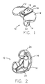
- a tibial base plate or support member 10 generally includes a top or proximal symmetrical supporting surface 12 and a lower or distal mounting stem 14.
- the upper surface 12 is substantially bisected by a proximally flared protrusion or rail 16 which extends substantially the entire anterior-posterior width of the base plate and, as will be described in more detail below, forms the first part of a dovetail coupling.
- the rail 16 is provided with a posterior upstanding stop 18 and a posteriorly angled (approximately 121 ⁇ 2) anterior counterbored screw hole 20.
- the stem 14 is angled posteriorly (approximately 31 ⁇ 2) and is buttressed by posteriorly angled (approximately 251 ⁇ 2) fins 22, 24.
- the support member 10 is preferably made of a cobalt chrome (Vitallium) alloy.
- a stabilizer tibial insert (bearing support member) 30 is a symmetrical plastic (UHMWPE) member having two upper or proximal bearing support surfaces 32, 34 which conform to the distal condyles of a femoral member (not shown), and a centrally located upstanding hollow stabilizer 36 which is dimensioned to serve as a substitute for the posterior cruciate ligament.
- a screw receiving hole is provided anterior of the stabilizer 36.
- the lower or distal surface 40 of the insert 30 is substantially bisected by a distally tapered groove 42 which is dimensioned to mate with the proximally flared rail 16 of the base plate 10 described above, and which forms the second part of a dovetail coupling.
- a posterior portion of the groove 42 is provided with a stop receiving slot 44 which allows the insert 30 to pass over the stop 18 on the baseplate 10 (( Figure 1) as will be described in more detail below.
- an insert support receiving well 46 is provided in an area of the groove 42 surrounding the lower hollow access to the stabilizer 36 and the screw hole 38. As will be described in more detail below, this well 46 is dimensioned to receive the base portion of the metallic stabilizer support member.
- the stabilizer insert 30 is intended to be used with a metallic (preferably cobalt chrome alloy) support member.
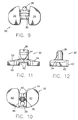
- Figures 13-16 illustrate a support member 50 according to the invention.
- the support member 50 is substantially L-shaped having a base portion 52 and a posterior upstanding portion 54.
- the base portion 52 is provided with a shouldered posteriorly angled (approximately 121 ⁇ 2) anterior screw hole 56.
- the base portion 52 is dimensioned to fit within the well 46 of the insert 30 ( Figure 8) with the upstanding portion 54 extending into the hollow stabilizer 36 and the hole 56 aligned with the hole 38.
- the aforedescribed components are easily assembled to form a tibial prosthesis 100 which is shown in Figures 17-22.
- the first step in the assembly is to place the upstanding portion 54 of the support 50 into the hollow stabilizer 36 of the insert 30 so that the base portion 52 of the support 50 is received in the well 46 of the insert 30 and the hole 56 in the support 50 aligns with the hole 38 in the insert 30.
- the subassembly resulting from the first step in the assembly process being described is generally made available as a preassembly.
- the insert 30, carrying the support 50 is positioned so that its posterior end faces the anterior end of the baseplate 10 and the groove 42 in the insert 30 is aligned with the rail 16 on the baseplate 10.
- the insert 30 is pushed posteriorly so that the rail 16 is embraced by the groove 42 and the base portion 52 of the support 50 abuts the stop 18 on the baseplate rail 16.
- the stop 18 prevents further posterior movement of the insert 30 and stops the insert 30 at a location where the hole 38 in the insert and the hole 56 in the support 50 are aligned with the hole 20 in the baseplate 10.
- a hexagon socket head shoulder screw 60 is inserted into the holes 38, 56, 20 and is screwed into threaded engagement with the baseplate 10.
- the hole 20 in the baseplate 10 has a broad unthreaded upper or proximal portion 20a which receives the shoulder of the screw 60, and a lower or distal narrow threaded portion 20b which receives and engages the threaded portion of the screw 60.
- the stem 14 of the baseplate 10 is provided with a threaded stem cap 70. This cap may be removed so that a stem extension can be added to stem 14.
- the central dovetail coupling of the insert 30 to the baseplate 10 will provide excellent torsional as well as vertical retention of the insert.
- the use of the shoulder screw 60, rather than a conventional socket head screw, provides an added benefit that, in addition to anterior-posterior retention of the insert, the screw is highly resistant to posteriorly applied shear loading.
- the increased resistance to shear loading is achieved by the larger diameter shoulder portion of the screw 60 and the lack of stress risers which are found in conventional screws due to their thread configuration.
- the prosthesis 100 is very easy to assemble and does not require very careful positioning of the components at the time of the assembly. Assembly does not require deformation of the insert as is required in many of the prior art devices.
- the coupling of the insert to the base plate also does not interfere with the thickness of the bearing portions of the insert.
- the tibial prosthesis of the invention may be made in several different sizes.
- the baseplate 10 has a medial-lateral width of approximately 2.44 inches and an anterior-posterior width of approximately 1.44 inches.
- the thickness of the base plate at the supporting surface 12 is approximately .117 inches
- the height of the rail 16 is approximately .173 inches
- the height of the stop 18 is approximately .286 inches relative to the supporting surface 12.
- the angle of the flare in the rail 16 is preferably approximately 601 ⁇ 2.
- the stem 14 is approximately 1.18 inches long and has an outer diameter of approximately .525 inches.
- the insert 30 will have corresponding dimensions to fit on the baseplate 10.
- the thickness of the bearing portions 32, 34 of the insert 30 (at pre-established gauge points) will range from approximately .430 inches to approximately .247 inches.
- the overall height of the insert (including the stabilizer 36) is approximately 1.174 inches.
- the support 50 used in the exemplary embodiment has an overall height of approximately .748 inches.
- the base portion of the support is approximately .505 inches by .729 inches and the diameter of the hole in the base portion is stepped from approximately .356 inches to approximately .258 inches.
- the shoulder screw 60 in this embodiment is approximately .635 inches long with a threaded length of approximately .220 inches and a shoulder diameter of approximately .239 inches.
Abstract
Description
Claims (23)
- A tibial prosthesis comprising:a) a base support member having a proximal supporting surface and a centrally located proximally flared protrusion which substantially bisects said supporting surface; andb) a bearing surface member having a pair of proximal bearing surfaces and a distal distally tapered groove, said distally tapered groove dimensioned to slideably embrace said proximally flared protrusion.
- A tibial prosthesis according to claim 1, wherein: said proximally flared protrusion defines a pair of substantially parallel dovetail coupling edges.
- A tibial prosthesis according to claim 1, wherein said base support member has a first screw receiving hole located in an anterior portion of said proximally flared protrusion, and said bearing surface member has an anterior second screw receiving hole which is aligned with said first screw receiving hole when said distally tapered groove embraces said proximally flared protrusion.
- A tibial prosthesis according to claim 3, further comprising:c) a shoulder screw dimensioned to pass through said second screw receiving hole and to engage threads in said first screw receiving hole.
- A tibial prosthesis according to claim 4, wherein said bearing surface member has a centrally located upstanding hollow stabilizer.
- A tibial prosthesis according to claim 5, further comprising:d) a substantially L-shaped support member having a base portion and an upstanding portion, said base portion including a counterbored third screw receiving hole and said upstanding portion dimensioned to fit inside said hollow stabilizer, wherein said shoulder screw is dimensioned to engage said base portion via said third screw receiving hole.
- A tibial prosthesis according to claim 6, wherein said proximally flared protrusion has an upstanding posterior stop which abuts said support member when said first, second and third screw receiving holes are aligned.
- A tibial prosthesis comprising:a) a base support member having a proximal supporting surface, a centrally located first dovetail coupling, and an anterior first screw receiving hole having a distal threaded portion and a proximal unthreaded portion;b) a bearing surface member having a pair of proximal bearing surfaces, a distal second dovetail coupling, and an anterior second screw receiving hole, said second dovetail coupling being dimensioned to mate with said first dovetail coupling with said first and second screw receiving holes being aligned with each other; andc) a shoulder screw dimensioned to pass through said second screw receiving hole and engage said distal threaded portion of said first screw receiving hole.
- A tibial prosthesis according to claim 8, wherein said bearing surface member has a centrally located upstanding hollow stabilizer.
- A tibial prosthesis according to claim 9, further comprising:d) a substantially L-shaped support member having a base portion and an upstanding portion, said base portion including a counterbored third screw receiving hole and said upstanding portion dimensioned to fit inside said hollow stabilizer, wherein said shoulder screw is dimensioned to engage said base portion via said third screw receiving hole.
- A tibial prosthesis according to claim 10, wherein said first dovetail coupling has an upstanding posterior stop which abuts said support member when said first, second and third screw receiving holes are aligned.
- A tibial prosthesis comprising:a) a base support member having a proximal supporting surface and a centrally located first dovetail coupling with an upstanding posterior stop;b) a bearing surface member having a pair of proximal bearing surfaces, an upstanding hollow stabilizer, and a centrally located distal second dovetail coupling, said second dovetail coupling dimensioned to slideably embrace said first dovetail coupling; andc) a stabilizer support member dimensioned to fit inside said upstanding hollow stabilizer and abut said posterior stop when said second dovetail coupling slideably embraces said first dovetail coupling.
- A tibial insert for use with a tibial baseplate having a proximal supporting surface and a centrally located proximally flared protrusion which substantially bisects said supporting surface, said insert comprising a bearing surface member having a pair of proximal bearing surfaces and a distal distally tapered groove, said distally tapered groove dimensioned to slideably embrace the proximally flared protrusion.
- A tibial insert according to claim 13, wherein said bearing surface member has a centrally located upstanding hollow stabilizer and an anterior screw receiving hole.
- A tibial base plate for use with a tibial insert having a pair of proximal bearing surfaces and a distal distally tapered groove, said base plate comprising a base support member having a proximal supporting surface and a centrally located proximally flared protrusion which substantially bisects said supporting surface and which is dimensioned to slideably embrace the distally tapered groove of the insert.
- A tibial base plate according to claim 15, further comprising an upstanding stop located on a posterior portion of said proximally flared protrusion.
- A tibial base plate according to claim 15, wherein said proximally flared protrusion has an anterior screw receiving hole, said hole having a distal threaded portion and a proximal unthreaded portion.
- A tibial base plate according to claim 17, wherein said screw receiving hole is dimensioned to receive a shoulder screw.
- A method for assembling a tibial prosthesis comprising the steps of:a) obtaining a base support member having a proximal supporting surface and a centrally located proximally flared protrusion which substantially bisects the supporting surface;b) obtaining a bearing surface member having a pair of proximal bearing surfaces and a distally tapered groove; andc) sliding the bearing surface onto the base support member so that the distally tapered groove embraces the proximally flared protrusion.
- A method for assembling a tibial prosthesis comprising the steps of:a) obtaining a base support member having a proximal supporting surface, a centrally located first dovetail coupling, and an anterior first screw receiving hole having a distal threaded portion and a proximal unthreaded portion;b) obtaining a bearing surface member having a pair of proximal bearing surfaces, a distal second dovetail coupling, and an anterior second screw receiving hole;c) obtaining a shoulder screw dimensioned to pass through the second screw receiving hole and engage the distal threaded portion at the first screw receiving hole;d) sliding the bearing surface member onto the base support member such that the second dovetail coupling mates with the first dovetail coupling and the first and second screw receiving holes are aligned with each other;e) inserting the shoulder screw through the first and second screw receiving holes; andf) threading the screw into the threaded portion of the first screw receiving hole.
- A method according to claim 20, further comprising the steps of:g) obtaining a substantially L-shaped support member having a base portion and an upstanding portion, the base portion including a counterbored third screw receiving hole, the bearing surface member having a hollow stabilizer portion dimensioned to receive the upstanding portion; andh) prior to said step of sliding, inserting the upstanding portion of the support member into the stabilizer portion so that the third screw receiving hole is aligned with the second screw receiving hole.
- A method for assembling a tibial prosthesis, comprising the steps of:a) obtaining a base support member having a proximal supporting surface and a centrally located first dovetail coupling with an upstanding posterior stop;b) obtaining a bearing surface member having a pair of proximal bearing surfaces, an upstanding hollow stabilizer, and a centrally located distal second dovetail coupling;c) obtaining a stabilizer support member dimensioned to fit inside the upstanding hollow stabilizer;d) inserting the stabilizer support member into the hollow stabilizer; ande) sliding the bearing surface member onto the base support member so that second dovetail coupling embraces the first dovetail coupling and the stabilizer support abuts the posterior stop.
- A method for assembling a tibial prosthesis, comprising the steps of:a) obtaining a base support member having a proximal supporting surface and a centrally located first dovetail coupling with an upstanding posterior stop;b) obtaining a bearing surface member having a pair of proximal bearing surfaces, an upstanding hollow stabilizer having a stabilizer support member inserted therein, and a centrally located distal second dovetail coupling; andc) sliding the bearing surface member onto the base support member so that second dovetail coupling embraces the first dovetail coupling and the stabilizer support abuts the posterior stop.
Applications Claiming Priority (2)
| Application Number | Priority Date | Filing Date | Title |
|---|---|---|---|
| US08/854,827 US5824103A (en) | 1997-05-12 | 1997-05-12 | Tibial prosthesis |
| US854827 | 1997-05-12 |
Publications (2)
| Publication Number | Publication Date |
|---|---|
| EP0878177A2 true EP0878177A2 (en) | 1998-11-18 |
| EP0878177A3 EP0878177A3 (en) | 1999-02-03 |
Family
ID=25319618
Family Applications (1)
| Application Number | Title | Priority Date | Filing Date |
|---|---|---|---|
| EP98303098A Withdrawn EP0878177A3 (en) | 1997-05-12 | 1998-04-22 | Tibial component of a knee prosthesis |
Country Status (3)
| Country | Link |
|---|---|
| US (1) | US5824103A (en) |
| EP (1) | EP0878177A3 (en) |
| JP (1) | JPH10314197A (en) |
Cited By (3)
| Publication number | Priority date | Publication date | Assignee | Title |
|---|---|---|---|---|
| US8211183B2 (en) | 2006-12-07 | 2012-07-03 | Ihip Surgical, Llc | Methods and systems for total hip replacement |
| US8241367B2 (en) | 2002-04-25 | 2012-08-14 | Zimmer, Inc. | Modular bone implant, tool, and method |
| US8579985B2 (en) | 2006-12-07 | 2013-11-12 | Ihip Surgical, Llc | Method and apparatus for hip replacement |
Families Citing this family (93)
| Publication number | Priority date | Publication date | Assignee | Title |
|---|---|---|---|---|
| US6004351A (en) * | 1996-09-14 | 1999-12-21 | Mizuho Ika Kogyo Kabushiki Kaisha | Prosthetic knee joint |
| US6139581A (en) * | 1997-06-06 | 2000-10-31 | Depuy Orthopaedics, Inc. | Posterior compensation tibial tray |
| US6280476B1 (en) * | 1998-10-16 | 2001-08-28 | Biomet Inc. | Hip joint prosthesis convertible in vivo to a modular prosthesis |
| US6500208B1 (en) | 1998-10-16 | 2002-12-31 | Biomet, Inc. | Nonmodular joint prosthesis convertible in vivo to a modular prosthesis |
| ATE369814T1 (en) * | 1998-10-16 | 2007-09-15 | Biomet Inc | FROM A NONMODULAR TO A MODULAR JOINT PROSTHESIS THAT CAN BE CONVERTED IN VIVO |
| AU771796B2 (en) * | 1999-02-03 | 2004-04-01 | Depuy Orthopaedics, Inc. | Modular joint prosthesis system |
| US6165223A (en) * | 1999-03-01 | 2000-12-26 | Biomet, Inc. | Floating bearing knee joint prosthesis with a fixed tibial post |
| US6413279B1 (en) | 1999-03-01 | 2002-07-02 | Biomet, Inc. | Floating bearing knee joint prosthesis with a fixed tibial post |
| US6217618B1 (en) * | 1999-10-26 | 2001-04-17 | Bristol-Myers Squibb Company | Tibial knee component with a mobile bearing |
| US6475241B2 (en) * | 2000-03-13 | 2002-11-05 | Biomedical Engineering Trust I | Posterior stabilized knee replacement with bearing translation for knees with retained collateral ligaments |
| US6558426B1 (en) | 2000-11-28 | 2003-05-06 | Medidea, Llc | Multiple-cam, posterior-stabilized knee prosthesis |
| US6355037B1 (en) | 2000-12-05 | 2002-03-12 | Smith & Nephew, Inc. | Apparatus and method of external skeletal support allowing for internal-external rotation |
| US6821470B2 (en) * | 2001-06-29 | 2004-11-23 | Depuy Products, Inc. | Joint prosthesis molding method |
| US6962607B2 (en) * | 2001-06-30 | 2005-11-08 | Depuy Products, Inc. | Joint replacement prosthesis component with non linear insert |
| US7892288B2 (en) | 2001-08-27 | 2011-02-22 | Zimmer Technology, Inc. | Femoral augments for use with knee joint prosthesis |
| US20030065397A1 (en) | 2001-08-27 | 2003-04-03 | Hanssen Arlen D. | Prosthetic implant support structure |
| US20040162619A1 (en) | 2001-08-27 | 2004-08-19 | Zimmer Technology, Inc. | Tibial augments for use with knee joint prostheses, method of implanting the tibial augment, and associated tools |
| US7572295B2 (en) | 2001-12-04 | 2009-08-11 | Active Implants Corporation | Cushion bearing implants for load bearing applications |
| US20030158606A1 (en) | 2002-02-20 | 2003-08-21 | Coon Thomas M. | Knee arthroplasty prosthesis and method |
| ATE431113T1 (en) | 2002-05-23 | 2009-05-15 | Active Implants Corp | JOINT AND DENTAL IMPLANTS |
| US20040002767A1 (en) * | 2002-06-28 | 2004-01-01 | Joseph Wyss | Modular knee joint prosthesis |
| USD684693S1 (en) | 2002-08-22 | 2013-06-18 | Zimmer, Inc. | Prosthetic implant support structure |
| AU2003287190A1 (en) | 2002-10-23 | 2004-05-13 | Alastair J. T. Clemow | Modular femoral component for a total knee joint replacement for minimally invasive implantation |
| US8105386B2 (en) * | 2003-02-04 | 2012-01-31 | Zimmer, Inc. | Rotating/non-rotating tibia base plate/insert system |
| US20050203632A1 (en) * | 2004-03-09 | 2005-09-15 | Daniels Michael E. | Tibial implant with a through post |
| US7160329B2 (en) | 2004-12-01 | 2007-01-09 | Mayo Foundation For Medical Research And Education | Radial-capitellar implant |
| EP1861047B1 (en) * | 2005-03-14 | 2017-05-31 | Inbone Acquisition Corp. | Ankle replacement system |
| US8974540B2 (en) | 2006-12-07 | 2015-03-10 | Ihip Surgical, Llc | Method and apparatus for attachment in a modular hip replacement or fracture fixation device |
| WO2008098250A2 (en) | 2007-02-10 | 2008-08-14 | Small Bone Innovations, Inc. | Radial head implant and related instrument |
| US8715359B2 (en) | 2009-10-30 | 2014-05-06 | Depuy (Ireland) | Prosthesis for cemented fixation and method for making the prosthesis |
| US20110035017A1 (en) * | 2007-09-25 | 2011-02-10 | Depuy Products, Inc. | Prosthesis with cut-off pegs and surgical method |
| US8470047B2 (en) * | 2007-09-25 | 2013-06-25 | Depuy (Ireland) | Fixed-bearing knee prosthesis |
| US7628818B2 (en) * | 2007-09-28 | 2009-12-08 | Depuy Products, Inc. | Fixed-bearing knee prosthesis having interchangeable components |
| US8128703B2 (en) * | 2007-09-28 | 2012-03-06 | Depuy Products, Inc. | Fixed-bearing knee prosthesis having interchangeable components |
| US8632600B2 (en) | 2007-09-25 | 2014-01-21 | Depuy (Ireland) | Prosthesis with modular extensions |
| US9204967B2 (en) | 2007-09-28 | 2015-12-08 | Depuy (Ireland) | Fixed-bearing knee prosthesis having interchangeable components |
| US9216085B2 (en) | 2008-02-28 | 2015-12-22 | Biopoly, Llc | Partial joint resurfacing implant, instrumentation, and method |
| CN102014800B (en) | 2008-02-28 | 2014-04-30 | 比奥波利公司 | Partial joint resurfacing implant, instrumentation, and method |
| US8696755B2 (en) * | 2008-04-17 | 2014-04-15 | Steven L. Mandell | Tibial component of an artificial knee joint |
| US8377073B2 (en) * | 2008-04-21 | 2013-02-19 | Ray Wasielewski | Method of designing orthopedic implants using in vivo data |
| EP2130518B1 (en) | 2008-06-03 | 2013-05-15 | DePuy Products, Inc. | Porous titanium femoral sleeves |
| ES2455090T3 (en) * | 2008-06-03 | 2014-04-14 | Depuy (Ireland) | Porous tibial titanium sleeves |
| US8206451B2 (en) | 2008-06-30 | 2012-06-26 | Depuy Products, Inc. | Posterior stabilized orthopaedic prosthesis |
| US8187335B2 (en) | 2008-06-30 | 2012-05-29 | Depuy Products, Inc. | Posterior stabilized orthopaedic knee prosthesis having controlled condylar curvature |
| US8192498B2 (en) | 2008-06-30 | 2012-06-05 | Depuy Products, Inc. | Posterior cructiate-retaining orthopaedic knee prosthesis having controlled condylar curvature |
| US9119723B2 (en) | 2008-06-30 | 2015-09-01 | Depuy (Ireland) | Posterior stabilized orthopaedic prosthesis assembly |
| US8236061B2 (en) | 2008-06-30 | 2012-08-07 | Depuy Products, Inc. | Orthopaedic knee prosthesis having controlled condylar curvature |
| US9168145B2 (en) | 2008-06-30 | 2015-10-27 | Depuy (Ireland) | Posterior stabilized orthopaedic knee prosthesis having controlled condylar curvature |
| US8828086B2 (en) | 2008-06-30 | 2014-09-09 | Depuy (Ireland) | Orthopaedic femoral component having controlled condylar curvature |
| US8187283B2 (en) * | 2008-09-30 | 2012-05-29 | Depuy Products, Inc. | Reusable orthopaedic instrument having drain holes |
| US9011547B2 (en) | 2010-01-21 | 2015-04-21 | Depuy (Ireland) | Knee prosthesis system |
| US8308808B2 (en) | 2010-02-19 | 2012-11-13 | Biomet Manufacturing Corp. | Latent mobile bearing for prosthetic device |
| WO2011153207A2 (en) | 2010-06-01 | 2011-12-08 | Smith & Nephew, Inc | Orthopaedic implant system and fasteners for use therein |
| CA2806321C (en) | 2010-07-24 | 2018-08-21 | Zimmer, Inc. | Asymmetric tibial components for a knee prosthesis |
| US8764840B2 (en) | 2010-07-24 | 2014-07-01 | Zimmer, Inc. | Tibial prosthesis |
| WO2012021764A2 (en) * | 2010-08-13 | 2012-02-16 | Smith & Nephew, Inc. | Orthopaedic implants and methods |
| EP3348236B1 (en) | 2010-09-10 | 2019-11-20 | Zimmer, Inc. | Motion facilitating tibial components for a knee prosthesis |
| US9597090B2 (en) | 2010-12-17 | 2017-03-21 | Zimmer, Inc. | Cut guide attachment for use in tibial prosthesis systems |
| US8603101B2 (en) | 2010-12-17 | 2013-12-10 | Zimmer, Inc. | Provisional tibial prosthesis system |
| US9149206B2 (en) * | 2012-03-30 | 2015-10-06 | Zimmer, Inc. | Tibial prosthesis systems, kits, and methods |
| US8728167B2 (en) | 2011-01-10 | 2014-05-20 | Howmedica Osteonics Corp. | Bicruciate retaining tibial baseplate design and method of implantation |
| EP2675398A4 (en) * | 2011-02-15 | 2017-01-25 | Omni Life Science, Inc. | Modular prosthesis |
| US8747479B2 (en) * | 2011-04-26 | 2014-06-10 | Michael A. McShane | Tibial component |
| EP2712308B1 (en) | 2011-05-20 | 2016-01-13 | Zimmer, Inc. | Stabilizing prosthesis support structure |
| US9814584B2 (en) | 2011-09-28 | 2017-11-14 | Depuy Ireland Unlimited Company | Fixed-bearing knee prosthesis having a locking mechanism with a concave-to-convex mating interface |
| WO2013074144A1 (en) | 2011-11-18 | 2013-05-23 | Zimmer, Inc. | Tibial bearing component for a knee prosthesis with improved articular characteristics |
| WO2013077919A1 (en) | 2011-11-21 | 2013-05-30 | Zimmer, Inc. | Tibial baseplate with asymmetric placement of fixation structures |
| US8911501B2 (en) | 2011-12-29 | 2014-12-16 | Mako Surgical Corp. | Cruciate-retaining tibial prosthesis |
| US9668871B2 (en) | 2011-12-29 | 2017-06-06 | Mako Surgical Corp. | Cruciate-retaining tibial prosthesis |
| EP2809273B1 (en) | 2012-01-30 | 2021-05-05 | Zimmer, Inc. | Asymmetric tibial components for a knee prosthesis |
| GB2524668A (en) | 2012-09-10 | 2015-09-30 | Acumed Llc | Radial head prosthesis with floating articular member |
| US9345578B2 (en) | 2013-02-22 | 2016-05-24 | Stryker Corporation | Bicruciate retaining tibial implant system |
| US9949837B2 (en) | 2013-03-07 | 2018-04-24 | Howmedica Osteonics Corp. | Partially porous bone implant keel |
| US9585758B2 (en) | 2013-03-12 | 2017-03-07 | Biomet Manufacturing, Llc | Knee prosthesis systems and methods |
| JP2016513551A (en) | 2013-03-15 | 2016-05-16 | マコ サージカル コーポレーション | Unicondylar tibial knee implant |
| US9925052B2 (en) | 2013-08-30 | 2018-03-27 | Zimmer, Inc. | Method for optimizing implant designs |
| US9592133B2 (en) | 2013-09-23 | 2017-03-14 | Zimmer, Inc. | Spacer block |
| US9820858B2 (en) * | 2015-03-23 | 2017-11-21 | Modal Manufacturing, LLC | Knee implants and instruments |
| CN108135701B (en) | 2015-09-21 | 2019-12-24 | 捷迈有限公司 | Prosthesis system including tibial bearing component |
| US9763792B2 (en) | 2015-10-01 | 2017-09-19 | Acumed Llc | Radial head prosthesis with rotate-to-lock interface |
| US10231840B2 (en) | 2016-07-27 | 2019-03-19 | Howmedica Osteonics Corp. | Low profile tibial baseplate with fixation members |
| AU2018210296B2 (en) | 2017-01-20 | 2020-05-07 | Biomet Manufacturing, Llc. | Modular augment component |
| US10905436B2 (en) | 2017-03-02 | 2021-02-02 | Optimotion Implants, Llc | Knee arthroplasty systems and methods |
| US11406502B2 (en) | 2017-03-02 | 2022-08-09 | Optimotion Implants LLC | Orthopedic implants and methods |
| US10675153B2 (en) * | 2017-03-10 | 2020-06-09 | Zimmer, Inc. | Tibial prosthesis with tibial bearing component securing feature |
| CA3063415C (en) | 2017-05-12 | 2021-10-19 | Zimmer, Inc. | Femoral prostheses with upsizing and downsizing capabilities |
| US11426282B2 (en) | 2017-11-16 | 2022-08-30 | Zimmer, Inc. | Implants for adding joint inclination to a knee arthroplasty |
| US10835380B2 (en) | 2018-04-30 | 2020-11-17 | Zimmer, Inc. | Posterior stabilized prosthesis system |
| USD901014S1 (en) | 2019-08-12 | 2020-11-03 | Ortho Development Corporation | Porous implant |
| USD901013S1 (en) | 2019-08-12 | 2020-11-03 | Ortho Development Corporation | Porous implant |
| US11565021B1 (en) | 2019-08-12 | 2023-01-31 | Ortho Development Corporation | Composite structure porous implant for replacing bone stock |
| USD901012S1 (en) | 2019-08-12 | 2020-11-03 | Ortho Development Corporation | Porous implant |
| US11498124B1 (en) | 2019-11-25 | 2022-11-15 | Ortho Development Corporation | Method for sintering porous structures from powder using additive manufacturing |
Citations (3)
| Publication number | Priority date | Publication date | Assignee | Title |
|---|---|---|---|---|
| US4963152A (en) | 1986-10-27 | 1990-10-16 | Intermedics Orthopedics, Inc. | Asymmetric prosthetic tibial component |
| US5358527A (en) | 1991-03-22 | 1994-10-25 | Forte Mark R | Total knee prosthesis with resurfacing and posterior stabilization capability |
| US5405396A (en) | 1993-07-01 | 1995-04-11 | Zimmer, Inc. | Tibial prosthesis |
Family Cites Families (15)
| Publication number | Priority date | Publication date | Assignee | Title |
|---|---|---|---|---|
| US4257129A (en) * | 1979-05-21 | 1981-03-24 | Volz Robert G | Prosthetic knee joint tibial implant |
| US5192324A (en) * | 1982-02-18 | 1993-03-09 | Howmedica Inc. | Bone prosthesis with porous coating |
| US4653488A (en) * | 1982-02-18 | 1987-03-31 | Howmedica, Inc. | Prosthetic knee implantation |
| CA1227002A (en) * | 1982-02-18 | 1987-09-22 | Robert V. Kenna | Bone prosthesis with porous coating |
| US4834756A (en) * | 1982-02-18 | 1989-05-30 | Pfizer Hospital Products Group, Inc. | Bone prosthesis with porous coating |
| US5194066A (en) * | 1988-01-11 | 1993-03-16 | Boehringer Mannheim Corporation | Modular joint prosthesis |
| US5035700A (en) * | 1988-02-03 | 1991-07-30 | Pfizer Hospital Products Group, Inc. | Prosthetic knee joint with improved patellar component tracking |
| US5007933A (en) * | 1989-01-31 | 1991-04-16 | Osteonics Corp. | Modular knee prosthesis system |
| US4938769A (en) * | 1989-05-31 | 1990-07-03 | Shaw James A | Modular tibial prosthesis |
| US5609639A (en) * | 1991-02-04 | 1997-03-11 | Walker; Peter S. | Prosthesis for knee replacement |
| US5395401A (en) * | 1991-06-17 | 1995-03-07 | Bahler; Andre | Prosthetic device for a complex joint |
| DE9111729U1 (en) * | 1991-09-19 | 1993-01-28 | Waldemar Link Gmbh & Co, 2000 Hamburg, De | |
| NZ243181A (en) * | 1992-04-23 | 1994-10-26 | Michael John Pappas | Prosthetic joint with guide means to limit articulation of a first element and bearing means to two degrees of freedom |
| US5370699A (en) * | 1993-01-21 | 1994-12-06 | Orthomet, Inc. | Modular knee joint prosthesis |
| FR2707870B1 (en) * | 1993-07-21 | 1995-10-13 | Essor Ste Civile | Bicondylar prosthesis of the posterior stabilized knee joint. |
-
1997
- 1997-05-12 US US08/854,827 patent/US5824103A/en not_active Expired - Fee Related
-
1998
- 1998-04-22 EP EP98303098A patent/EP0878177A3/en not_active Withdrawn
- 1998-05-08 JP JP10125954A patent/JPH10314197A/en active Pending
Patent Citations (3)
| Publication number | Priority date | Publication date | Assignee | Title |
|---|---|---|---|---|
| US4963152A (en) | 1986-10-27 | 1990-10-16 | Intermedics Orthopedics, Inc. | Asymmetric prosthetic tibial component |
| US5358527A (en) | 1991-03-22 | 1994-10-25 | Forte Mark R | Total knee prosthesis with resurfacing and posterior stabilization capability |
| US5405396A (en) | 1993-07-01 | 1995-04-11 | Zimmer, Inc. | Tibial prosthesis |
Cited By (4)
| Publication number | Priority date | Publication date | Assignee | Title |
|---|---|---|---|---|
| US8241367B2 (en) | 2002-04-25 | 2012-08-14 | Zimmer, Inc. | Modular bone implant, tool, and method |
| US8211183B2 (en) | 2006-12-07 | 2012-07-03 | Ihip Surgical, Llc | Methods and systems for total hip replacement |
| US8579985B2 (en) | 2006-12-07 | 2013-11-12 | Ihip Surgical, Llc | Method and apparatus for hip replacement |
| US9237949B2 (en) | 2006-12-07 | 2016-01-19 | Ihip Surgical, Llc | Method and apparatus for hip replacement |
Also Published As
| Publication number | Publication date |
|---|---|
| JPH10314197A (en) | 1998-12-02 |
| US5824103A (en) | 1998-10-20 |
| EP0878177A3 (en) | 1999-02-03 |
Similar Documents
| Publication | Publication Date | Title |
|---|---|---|
| US5824103A (en) | Tibial prosthesis | |
| US5019103A (en) | Tibial wedge system | |
| EP1430856B1 (en) | Modular prosthetic knee implant system comprising femoral stem augment | |
| US8118868B2 (en) | Method and apparatus for attaching soft tissue to an implant | |
| US8556980B2 (en) | Glenoid augment and associated method | |
| US5766255A (en) | Modular joint prosthesis stabilization and augmentation system | |
| US5480444A (en) | Hybrid tibial tray knee prosthesis | |
| US4963152A (en) | Asymmetric prosthetic tibial component | |
| US5755800A (en) | Modular joint prosthesis augmentation system | |
| US5413605A (en) | Tibial element for a replacement knee prosthesis | |
| US5326365A (en) | Ankle implant | |
| US4731087A (en) | Metatarsal-phalangeal prosthesis | |
| US20050154470A1 (en) | Modular phrosthesis assembly including tapered adjustments | |
| EP1417938A1 (en) | Constrained prosthetic knee with rotating bearning | |
| EP1226800A2 (en) | Constrained Prosthetic knee with rotating bearing | |
| US20030233149A1 (en) | Porous unicondylar knee | |
| US20120245701A1 (en) | Hemi Ankle Implant | |
| US20040143336A1 (en) | Two-piece modular patellar prosthetic system | |
| US20040133282A1 (en) | Semi-constrained ankle prosthesis with a front loading polymer bearing | |
| WO2013063314A1 (en) | Knee prosthesis | |
| US20020120341A1 (en) | Prosthetic revision knee system | |
| US11344420B2 (en) | Modular knee prosthesis | |
| US11596519B2 (en) | Hinge knee assembly guide | |
| US20240082012A1 (en) | Glenoid replacement system and methods of implanting said glenoid replacement | |
| JP2000000256A (en) | Tibia prosthesis device as well as its assembling |
Legal Events
| Date | Code | Title | Description |
|---|---|---|---|
| PUAI | Public reference made under article 153(3) epc to a published international application that has entered the european phase |
Free format text: ORIGINAL CODE: 0009012 |
|
| AK | Designated contracting states |
Kind code of ref document: A2 Designated state(s): CH DE ES FR GB LI NL |
|
| AX | Request for extension of the european patent |
Free format text: AL;LT;LV;MK;RO;SI |
|
| PUAL | Search report despatched |
Free format text: ORIGINAL CODE: 0009013 |
|
| AK | Designated contracting states |
Kind code of ref document: A3 Designated state(s): AT BE CH CY DE DK ES FI FR GB GR IE IT LI LU MC NL PT SE |
|
| AX | Request for extension of the european patent |
Free format text: AL;LT;LV;MK;RO;SI |
|
| 17P | Request for examination filed |
Effective date: 19990708 |
|
| AKX | Designation fees paid |
Free format text: CH DE ES FR GB LI NL |
|
| RAP1 | Party data changed (applicant data changed or rights of an application transferred) |
Owner name: STRYKER TECHNOLOGIES CORPORATION |
|
| 17Q | First examination report despatched |
Effective date: 20010822 |
|
| STAA | Information on the status of an ep patent application or granted ep patent |
Free format text: STATUS: THE APPLICATION IS DEEMED TO BE WITHDRAWN |
|
| 18D | Application deemed to be withdrawn |
Effective date: 20020718 |