EP0876825A2 - Intravenous tube slide clamp with sliding preventor - Google Patents
Intravenous tube slide clamp with sliding preventor Download PDFInfo
- Publication number
- EP0876825A2 EP0876825A2 EP98202761A EP98202761A EP0876825A2 EP 0876825 A2 EP0876825 A2 EP 0876825A2 EP 98202761 A EP98202761 A EP 98202761A EP 98202761 A EP98202761 A EP 98202761A EP 0876825 A2 EP0876825 A2 EP 0876825A2
- Authority
- EP
- European Patent Office
- Prior art keywords
- clamp
- occluding
- slide
- tube
- slide clamp
- Prior art date
- Legal status (The legal status is an assumption and is not a legal conclusion. Google has not performed a legal analysis and makes no representation as to the accuracy of the status listed.)
- Granted
Links
Images


Classifications
-
- A—HUMAN NECESSITIES
- A61—MEDICAL OR VETERINARY SCIENCE; HYGIENE
- A61M—DEVICES FOR INTRODUCING MEDIA INTO, OR ONTO, THE BODY; DEVICES FOR TRANSDUCING BODY MEDIA OR FOR TAKING MEDIA FROM THE BODY; DEVICES FOR PRODUCING OR ENDING SLEEP OR STUPOR
- A61M39/00—Tubes, tube connectors, tube couplings, valves, access sites or the like, specially adapted for medical use
- A61M39/22—Valves or arrangement of valves
- A61M39/28—Clamping means for squeezing flexible tubes, e.g. roller clamps
- A61M39/281—Automatic tube cut-off devices, e.g. squeezing tube on detection of air
-
- A—HUMAN NECESSITIES
- A61—MEDICAL OR VETERINARY SCIENCE; HYGIENE
- A61M—DEVICES FOR INTRODUCING MEDIA INTO, OR ONTO, THE BODY; DEVICES FOR TRANSDUCING BODY MEDIA OR FOR TAKING MEDIA FROM THE BODY; DEVICES FOR PRODUCING OR ENDING SLEEP OR STUPOR
- A61M39/00—Tubes, tube connectors, tube couplings, valves, access sites or the like, specially adapted for medical use
- A61M39/22—Valves or arrangement of valves
- A61M39/28—Clamping means for squeezing flexible tubes, e.g. roller clamps
- A61M39/286—Wedge clamps, e.g. roller clamps with inclined guides
- A61M39/287—Wedge formed by a slot having varying width, e.g. slide clamps
-
- A—HUMAN NECESSITIES
- A61—MEDICAL OR VETERINARY SCIENCE; HYGIENE
- A61M—DEVICES FOR INTRODUCING MEDIA INTO, OR ONTO, THE BODY; DEVICES FOR TRANSDUCING BODY MEDIA OR FOR TAKING MEDIA FROM THE BODY; DEVICES FOR PRODUCING OR ENDING SLEEP OR STUPOR
- A61M2205/00—General characteristics of the apparatus
- A61M2205/60—General characteristics of the apparatus with identification means
-
- A—HUMAN NECESSITIES
- A61—MEDICAL OR VETERINARY SCIENCE; HYGIENE
- A61M—DEVICES FOR INTRODUCING MEDIA INTO, OR ONTO, THE BODY; DEVICES FOR TRANSDUCING BODY MEDIA OR FOR TAKING MEDIA FROM THE BODY; DEVICES FOR PRODUCING OR ENDING SLEEP OR STUPOR
- A61M5/00—Devices for bringing media into the body in a subcutaneous, intra-vascular or intramuscular way; Accessories therefor, e.g. filling or cleaning devices, arm-rests
- A61M5/14—Infusion devices, e.g. infusing by gravity; Blood infusion; Accessories therefor
- A61M5/142—Pressure infusion, e.g. using pumps
- A61M5/14212—Pumping with an aspiration and an expulsion action
- A61M5/14228—Pumping with an aspiration and an expulsion action with linear peristaltic action, i.e. comprising at least three pressurising members or a helical member
-
- Y—GENERAL TAGGING OF NEW TECHNOLOGICAL DEVELOPMENTS; GENERAL TAGGING OF CROSS-SECTIONAL TECHNOLOGIES SPANNING OVER SEVERAL SECTIONS OF THE IPC; TECHNICAL SUBJECTS COVERED BY FORMER USPC CROSS-REFERENCE ART COLLECTIONS [XRACs] AND DIGESTS
- Y10—TECHNICAL SUBJECTS COVERED BY FORMER USPC
- Y10S—TECHNICAL SUBJECTS COVERED BY FORMER USPC CROSS-REFERENCE ART COLLECTIONS [XRACs] AND DIGESTS
- Y10S128/00—Surgery
- Y10S128/12—Pressure infusion
Definitions
- the present invention relates in general to a slide clamp useable to control the flow of medical fluid to an I.V. tubing.
- Intravenous fluids to a patient is well known in the art.
- a solution such as saline, glucose or electrolyte in a glass or flexible container is fed to a patient's venous access site via a length of flexible plastic I.V. tubing such as polyvinyl chloride (PVC) tubing.
- I.V. tubing such as polyvinyl chloride (PVC) tubing.
- the rate of flow of the fluid is controlled by a roller clamp which is adjusted to restrict the flow lumen of the I.V. tubing until the desired flow rate is obtained.
- Flow from the container to the patient may also be regulated by means other than a roller clamp. It is becoming more and more common to use an electronically controlled pump. Once type of pump that is used for intravenous fluid administration is a peristaltic-type pump.
- peristaltic pumping action is particularly well suited for the medical field. This is because peristaltic pumping action can be applied externally of the I.V. tubing carrying the intravenous fluid. This maintains the sterile condition of the intravenous fluid within the I.V. tubing while imparting fluid propulsion on the fluid. The peristaltic pumping action can also be applied on any point on the I.V. tubing.
- a driving motor is connected to an array of cams which are angularly spaced from each other.
- the cams in turn drive cam followers which are connected to corresponding pressure fingers.
- These elements cooperate to impart a linear wave motion on the pressure fingers.
- a pressure plate is secured juxtaposed to and spaced from the pressure fingers. The pressure plate holds the I.V. tubing against the reciprocating pressure fingers to impart the wave motion on the I.V. tubing to propel the fluid.
- a driving motor is connected via an armature to at least one roller member.
- the driving motor imparts a circular rotation on the armature which actuates the roller member.
- a semicircular pressure plate having the same center point as the armature is provided with the I.V. tubing located between the roller member and the pressure plate. The pressure plate holds the I.V. tubing against the roller member which imparts a circular motion on the I.V. tubing to propel the fluid.
- peristaltic pumps One drawback of the use of peristaltic pumps is that, because when loaded into the pump the peristaltic action drives the propulsion of the fluid, prior to loading into the pump, the I.V. tubing is often left in an open condition. While a straightforward solution to this problem is to simply provide a roller or other flow clamp on the I.V. tubing to occlude the I.V. tubing prior to loading and after removal, this creates the possibility that the health care professional loading the I.V. tubing into the peristaltic pump will forget to open the I.V. tubing after loading has been completed.
- Prior art slide clamps generally include a regulating aperture defining an occluding slot and a non-occluding passage.
- An I.V. tube inserted through the regulating aperture in an operative position is slidable transverse to the length of the tube between the non-occluding passage and the occluding slot to control the flow of fluid through the lumen of the I.V. tube.
- prior art slide clamps tend to slide longitudinally of the I.V. tube under the effect of gravity. Often, this sliding makes it difficult and cumbersome for medical personnel to quickly locate the slide clamp to occlude flow at a desired position along the length of the I.V. tube.
- the tube contacting surface of the flow regulating aperture typically extends over the entire depth of the slide clamp.
- prior art slide clamps leave a relatively wide surface contacting an I.V. tube in an operative position, providing a significant frictional force opposing sliding of an I.V. tube relative to the slide clamp between the non-occluding passage and the occluding slot. Both of these features make it relatively difficult to use prior art slide clamps with a safety mechanism for use in a peristaltic pump.
- US-A-4434963 discloses a slide clamp of the type with which the invention is concerned.
- the precharacterising part of Claim 1 is based on the disclosure of this document and the present invention is distinguished by the characterising part of Claim 1.
- US-A-4434963 discloses an arrangement in which an I.V. tube can be slid from a non-occluding passage to an occluding slot.
- the non-occluding passage has a generally cylindrical form, but opposite to the entrance to the occluding slot, projections extend into the passage to reduce the risk of slippage of the clamp under gravity.
- US-A-4248401 and US-A-3374509 each disclose a part-cylindrical end surface, opposite to the occluding slot and no projections.
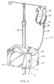
- FIG. 1 is an illustration of an intravenous administration setup using a pump and a source of intravenous fluid such as a flexible container.
- the pump includes pump housing 20 which includes pump operating mechanics and operating electronics (not shown).
- the pump is mounted on an I.V. stand 22, which also serves a support for the intravenous fluid container 24.
- An administration set 10 provides a flow path from the container 24 to the patient via the pump.
- the set 10 includes a segment of flexible plastic I.V. tubing 26 such as polyvinyl chloride (PVC) tubing.
- PVC polyvinyl chloride
- the I.V. tubing 26 at its proximal end is attached to a drip chamber 28 that is in turn attached via a spike (not shown) to an outlet port 30 of the container 24.
- I.V. tubing 26 has connected at its distal end means for connecting the set 10 to a vein access device, such as a catheter or a needle (not shown).
- the pump includes a hinged door 36 which covers the peristaltic pumping apparatus hardware. To set up the pump, the door 36 is opened, the I.V. tubing 26 is inserted into the peristaltic pump apparatus as described in detail below, the door is closed, and the pump is activated. The pump also defines apertures at the upper 38 and lower 42 peripheries of the pump housing 20 through which the I.V. tubing 26 extends when the door 36 is closed. Additionally, the door 36 includes a latch 32 which can be pivoted from a released position in which the door 36 is not locked and a latching position in which the door 36 is locked in the closed position.
- FIG. 1 While the apparatus depicted in Figure 1 includes a dual drive peristaltic pump, use of any number of pump drives in a single peristaltic pump is contemplated.
- An inlet groove 29 is provided leading from the access aperture 38 to a peristaltic pumping member in a form of a plurality of receptacle fingers 31.
- An outlet groove 33 is provided from the fingers 31 to the lower aperture 42.
- An upstream occlusion sensor 35 is provided on the inlet groove 29 while a downstream occlusion sensor 37 is provided on the outlet groove 33.
- An air bubble detector 39 is also provided on the outlet groove 33.
- the door 36 of the pump includes a spring-loaded backplate 43 of conventional construction as well as the cooperating members for the upstream occlusion detector 35, downstream occlusion detector 37, and bubble detector 39.
- a fixed latch member 55 is provided that acts in cooperating relationship with the latch member 32 to securely latch or lock the door 36 in a closed position.
- the I.V. tube 26 can be loaded into the inlet groove 29 extending straight across the reciprocal fingers 31 as guided by a plurality of I.V. tube guides 41 and into the outlet groove 33.
- the latch 32 mates with the fixed latch member 55 to latch or lock the door in a closed position.
- the safety apparatus includes an upper safety clamp housing 50 and a lower slide clamp housing, chamber 52.
- the safety apparatus defines as an extension of the outlet groove 33, an I.V. tube groove 54 into which the I.V. tube fits.
- Extending perpendicularly from the I.V. tube groove 54 is a retainer arm aperture 56 defined in the lower slide clamp housing 52.
- a right cooperating retainer arm 58 and left cooperating retainer arm 61 Contained in the retainer arm aperture 56 are a right cooperating retainer arm 58 and left cooperating retainer arm 61 which pivot from an open or loaded position to a retaining or unloaded position in which the distance between the two retainer arms 58,61 is smaller relative to the position of the retainer arms 58,61 in the open or loaded position.
- the central portion of the retainer arm aperture 56 between the cooperating retainer arms 58,61 defines the receiving area 62 for a slide clamp.
- a release pin 63 Contained on the upper safety clamp housing 50 is a release pin 63 which extends outwardly from and is capable of reciprocating into and out of the upper safety clamp housing 50.
- the release pin 63 activates a sliding mechanism which orients the slide clamp from an occluded to an open position.
- the safety clamp 65 is capable of extending into the I.V. tube groove 54 to occlude the I.V. tube.
- the further functioning of the safety clamp 65 and release pin 63 will be described in detail below in conjunction with Figures 4, 5 and 6.
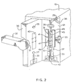
- FIG 4 a cross sectional upper view of the lower slide clamp housing 52 of the safety apparatus is seen.
- the slide clamp housing 52 is seen in an initial or preactivated condition.
- the lower slide clamp housing 52 contains the right retainer arm 58 and the left retainer arm 61. Contained on each retainer arm 58,61 is a pivot point 67 which allows the rotational pivoting of each of the retainer arms 58,61. Further contained on the end opposite the pivot point 67 of each retainer arm 58,61 is an inwardly extending retainer finger 69 which, in cooperation with the retaining finger 69 of the cooperating retainer arm, acts to retain the slide clamp as described below.
- Each retainer arm 58,61 includes biasing means which, in a preferred embodiment, can be a spring 74 which pivotally biases each retainer arm 58,61 towards the cooperating retainer arm in the retained position. However, in the preactivated or loaded position, the retainer arms 58,61 are held against the bias in the open position.
- the left retainer arm 61 further includes an upwardly protruding stepped portion 76 which extends upwardly into the upper safety clamp housing 50.
- This stepped portion 76 acts as a retaining member as will be described in detail with reference to Figure 5.
- I.V. tube groove housing 78 which defines the I.V. tube groove 54.
- the I.V. tube groove 54 is an extension of the outlet groove 33 of the pump 20.
- the I.V. tube groove 54 enables the I.V. tube to be retained in the appropriate position in both the pump 20 and the safety apparatus.
- the I.V. tube groove 54 is located centrally between the cooperating retainer arms 58,61. This acts to center the slide clamp contained on the I.V. tube between the retainer arms 58,61.
- a slide member 81 Contained distally from the I.V. tube groove 54 is a slide member 81 which is contained on a pair of cooperating slide rails 83 which allow for inward and outward reciprocal movement of the slide member 81.
- the slide member 81 includes an outwardly extending biasing means which biases the slide member 81 towards the I.V. tube groove 54.
- the outwardly extending biasing means is a spring 87.
- the slide member 81 includes cam surfaces 89 extending outwardly on each side. The cam surfaces 89 act in cooperation with the cam followers 72 of the retainer arms 58,61 to pivot the retainer arms 58,61.
- a nonobstructive sensor 85 such as an electronic eye which can be used to sense the presence of a slide clamp.
- Electronic eye 85 is positioned to sense when the slide clamp has been inserted into the slide clamp receiving area.
- the electronic eye 85 is in electronic communication with the pump operating electronics.
- the electronic eye 85 senses the fully inserted slide clamp; if a fully inserted slide clamp is not sensed, the operating electronics prevents the pump from operating.
- the non-obstructive sensor 85 will be described in further detail below in conjunction with Figure 12. Use of alternatives such as a warning or an informational message will also be appreciated as possible.
- a slide shaft 92 Contained extending inwardly from the slide member 81 is a slide shaft 92.
- the slide shaft 92 is housed in a slide shaft aperture 94 defined in the lower slide clamp housing 52 and extending inwardly from the I.V. tube groove 54.
- the slide shaft 92 includes a notched portion 96 defined therein.
- a slide latch 98 is also provided housed in a slide latch aperture 101 defined in the lower slide clamp housing 52 and extending perpendicularly to the slide shaft aperture 94.
- the slide latch 98 includes a cam follower 103.
- the slide latch 98 is biased towards the slide shaft 92 by biasing means such as a spring 105.
- the slide latch 98 thus acts in conjunction with the notched portion 96 of the slide shaft 92 to retain the slide shaft 92 and thus the sliding member 81 against the outward bias of the spring 87. In the retained position, the sliding member 81 is in a loaded position while in the unretained or outward position, the sliding member 81 is in an unloaded position. It should be noted that the slide latch 98 and the notched portion 96 of the slide shaft 92 employ cooperating angled surfaces 107 which allow the slide shaft 92 to exhibit an amount of play the purpose of which will be discussed below.
- the slide clamp 109 includes a regulating aperture 110 which includes a thin occluding slot 111 and a wider non-occluding passage 112.
- the slide clamp 109 includes an access slit 113 which allows the I.V. tube 26 to be positioned into the regulating aperture 110 without requiring the slide clamp 109 to be threaded from an end of the I.V. tube 26.
- the slide clamp 109 includes projections 114 which extend inwardly into the non-occluding passage 112 of the regulating aperture 110.
- the projections 114 act to maintain frictional contact against the I.V. tube 26 when the I.V. tube 26 is in the non-occluding passage 112 in an operative position while not causing an occlusion of the I.V. tube 26.
- the slide clamp 109 can be selectively positionally retained longitudinally of the I.V. tube 26 against the force of gravity yet moved longitudinally under a force in excess of the force of gravity.
- the slide clamp 109 has notches 115 on each oppositely facing side proximal to the non-occluding portion 112 of the regulating aperture 110. These notches 115 act in cooperation with the retaining fingers 69 of the retaining arms 58,61 to secure the slide clamp 109 in the slide clamp housing 52 when the slide clamp 109 has been inserted and the retainer arms 58,61 are unloaded.
- the distal portion of the slide clamp 109 is further defined by increased width outward projections 116. These outward projections 116 prevent inadvertent backward insertion of the slide clamp 109 into the slide clamp housing 52.
- a slide clamp which is not according to the claimed invention, is indicated as 109' in Figure 7 with elements corresponding to those of the slide clamp 109 having the same reference number followed by a "/" .
- the slide clamp 109' includes a body 117 having a leading edge 118, a trailing edge 119 and first and second oppositely facing sides 120,121.
- the slide clamp 109' includes a regulating aperture 110' having an occluded slot 111' and a non-occluding passage 112', all substantially identical to those of the slide clamp 109.
- Notches 115' are located in the first and second oppositely facing sides 120,121.
- Outer width projections 116' on the trailing edge 119 function in the same manner as the outward projections 116 on the slide clamp 109 to prevent inadvertent backward insertion of the slide clamp 109' into the slide clamp housing 52.
- An I.V. tube 26 is illustrated in ghost lines in an operative position extending through the non-occluding passage 112' of the regulating aperture 110'.
- the non-occluding passage 112' is configured to provide first, second and third I.V. tube contact points 122. Together the contact points 122 define an I.V. tube receiving space.
- the I.V. tube 26 has an outer diameter 123 equal to or slightly greater than the I.V. tube receiving space defined by the contact points 122. In this manner, the contact points 122 act to maintain frictional contact against the outer diameter 123 of the I.V. tube 26 while not causing any occlusion of the flow lumen 124 of the I.V. tube 26.
- the contact points 122 maintain sufficient frictional contact with the I.V. tube 26 that the slide clamp 109' cannot move longitudinally of an I.V. tube under the force of gravity, but requires a selected force in excess of the force of gravity to move the slide clamp 109' longitudinally of an I.V. tube 26.
- the slide clamp 109' also includes a surface pad 125.
- the surface pad 125 reflects a beam of light from the non-obstructive sensor 85, as will be discussed in more detail below with reference to Figure 12.
- the pad 125 is located in a precise selected position on the slide clamp 109' to insure proper cooperation with the non-obstructive sensor 85.
- the surface pad 125 is provided with a shiny finish (such as a No.2 finish) to aid in reflecting a light beam transmitted by the non-obstructive sensor 85.
- the top and bottom (not shown) of the slide clamp 109' are mirror images so that slide clamp 109' can be inserted into the slide clamp housing 52 with either the top or bottom orientated upward.
- the slide clamps 109,109' are preferably injection molded from polypropylene.
- the clamps could also be made from PETG, co-polyester or DERLINTM.
- the necessary characteristics of the slide clamp material are that it be moldable within close tolerances and rigid enough to withstand pressures of up to 310.275 kPa (45 psi) within the I.V., tube.
- the slide clamp material must be able to withstand EtO and gamma sterilization without impairing the functionality of the clamp.
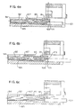
- FIG 8 illustrates in cross-section the preferred profile of the occluding slot 111'.
- the occluding slot has an I.V. tube contacting surface 126 of a length L less than the distance W between the top and bottom surfaces 127,128 of the slide clamp 109'.
- Between the top and bottom surfaces 127,128 and the I.V. contacting surface 126 are guiding surfaces 129.
- the guiding surfaces 129 constitute beveled edges between the I.V. contacting surface 126 and the top and, bottom surfaces 127,128.
- the I.V. contacting surface 126 of a length L less than the distance W between the top and bottom surfaces 127,128 along with the beveled I.V.
- FIG. 10 illustrates a slide clamp wherein the I.V. tube contacting surface is a length L equal to the distance W between the top and bottom surfaces of a slide clamp, providing a large frictional surface to oppose sliding of the I.V. tube between the I.V. tube contacting surfaces.
- Figure 11 illustrates a slide clamp having an arcuate I.V. contacting surface. As seen in Figure 11, the entire arcuate surface contacts the I.V. tube, again creating a relatively large frictional surface to oppose movement of the I.V. tube 26 through the occluding slot. Thus, the profile illustrated in Figure 8 permits a relatively thick body 117.
- the I.V. contacting surface 126 has a length L of between 0.152 and 0.508mm (.006 and .02 inches). Preferably, the length L is between 0.254 and 0.356mm (.01 and .014 inches).
- the angle A between the I.V. tube contacting surface 126 and the top and bottom surfaces 127,128 must be sufficient so that the guiding surfaces 129 do not contact the I.V. tube 26. Preferably, the angle A is in a range of between 25°-45°, with an angle of 35° being ideal.
- acceptable slot dimensions for use with PVC tubing having inner diameter and a 0.483mm (0.019 inch) wall thickness are as follows:
- FIG 12 illustrates the non-obstructive sensor 85.
- the non-obstructive sensor 85 includes an optical light source 200 and an optical light sensor 202.
- the optical light source 200 emits a beam of light 204 directed onto the surface pad 125 of the I.V. clamp 109'.
- a portion 206 of the light beam 204 is reflected off the surface pad 125 and received by, the optical light sensor 202.
- the optical light sensor 202 is in a first state in response to receiving a reflected light beam within a selected band width and of a selected intensity and in a second state in response to not receiving a reflected light beam within the selected intensity and band width.
- a switch 208 in electrical communication with the optical light sensor 202 disables the pump in response to the optical light sensor 202 being in the second state.
- the optical sensor 202 will not be in the second state and the pump will not function.
- the non-obstructive sensor 85 described herein verifies that a slide clamp inserted into the clamp receiving area is compatible with the safety apparatus. Consequently, catastrophic injury to patients resulting from the use of functionally incompatible slide clamps can be prevented.
- the slide clamp 109 is shown inserted into the slide clamp housing 52.
- the end opposite the outward projections 116 is inserted into the slide clamp housing 52. This results in the non-occluding passage 112 of the regulating aperture 110 being inserted first.
- the action of the health care professional manually inserting the slide clamp 109 into the slide clamp housing 52 in conjunction with the I.V. tube groove 54 assures that, after full insertion, the I.V. tube 26 is positioned in the occluding slot 111 of the slide clamp 109.
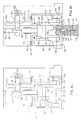
- FIG 5 a cutaway view of the upper safety clamp housing 50 is seen.
- the position of the elements of the upper safety clamp housing 50 in Figures 5a-5f correspond to the position of the elements of the lower slide clamp housing 50 in Figures 4a-4f.
- the safety clamp housing 50 includes the generally L-shaped safety clamp 65.
- the safety clamp 65 includes an occluding member 130 which is capable of extending into the I.V. tube groove 54 and acting in cooperation with an occluding base 132 to occlude the I.V. tube 26.
- the generally L-shaped safety clamp 65 includes a pivot point 134 which allows the safety clamp 65 to alternatively pivot from an occluded state seen in Figure 5e to a non-occluding state seen in Figure 5a.
- a latching segment 136 having a latching notch 138 is defined which acts in cooperation with a safety latch 140 which will be described in detail below.
- the left retainer arm 61 includes an upwardly protruding stepped portion 76 which extends upwardly into the upper safety clamp housing 50.
- the upwardly protruding stepped portion 76 of the left retaining arm 61 is oriented in the upper safety clamp housing 50 adjacent to the safety clamp 65.
- the stepped portion 76 prevents the safety clamp 65 from fully pivoting through interference with downward protruding stepped portion 200 of safety clamp 65 while when the left retaining arm 61 is in the open position, the safety clamp 65 is allowed to fully pivot.
- the upper safety clamp housing 50 further includes a generally L-shaped safety latch 140.
- the safety latch 140 includes a pivot point 142 which allows the safety latch 140 to pivot from an engaged to a non-engaged position.
- the safety latch 140 and safety clamp 65 are both biased by biasing means which bias the safety clamp 65 towards the occluded position and bias the safety latch 140 towards the safety clamp 65.
- the biasing means is a spring 144 connected between a spring attachment point 146 on the upper portion of the generally L-shaped safety clamp 65 and a spring attachment point 148 on thd lower portion of the generally L-shaped safety latch 140. Use of a single spring 144 in conjunction with the pivot points 134,142 and the spring attachments points 146,148 results in two different moments achieved by a single spring 144.
- the safety latch 140 includes at the end opposite the spring attachment point 148 a latching mechanism 151 which acts in cooperative latching orientation with the safety clamp latching notch 138. Additionally, the safety clamp 65 and the safety latch 140 are biased by the spring 144 such that when the safety clamp 65 is in the non-occluding state, the safety latch 140 can pivot into the engaged position to catch the latching notch 138 in the safety clamp 65 to maintain the safety clamp 65 in the non-occluding state as depicted in Figure 5c. Alternatively, when the safety clamp 65 is in the occluded state, the safety latch 140 has pivoted out of the way into the non-engaged position and is thus nonoperative so the bias of the spring 144 can maintain the safety clamp 65 in the occluded state.
- the upper safety clamp housing 50 further includes the release pin 63.
- the release pin 63 is outwardly biased by biasing means such as a spring 153.
- the release pin 63 is engaged with the safety latch by a pivot point 155 such that back and forth movement of the release pin 63 causes pivoting movement of the safety latch 140.
- the release pin 63 further includes a release arm 157 which includes a downwardly extending cam surface 159.
- the downwardly extending cam surface 159 acts cooperatively with the cam follower 103 of the slide latch 98 such that back and forth movement of the release pin 63 causes the slide latch 98 to slide.
- the safety clamp 65 Prior to loading the slide clamp 109 into the lower slide clamp housing 52, the safety clamp 65 can be in either the occluded or non-occluding state. If in the occluded state, the left retainer arm 61 is in the open state which allows the safety clamp 65 to be fully pivoted to the non-occluding state. When pivoted to the non-occluding state, the safety latch 140 will catch and maintain the safety clamp 65 in the non-occluding state and the I.V. tube 26 can be loaded.
- the door 36 includes a stepped inlet 162.
- the stepped inlet 162 includes a first stepped portion 164 corresponding to the safety clamp 65.
- the stepped inlet 162 includes a second stepped portion 166 corresponding to the release pin 63.
- the stepped portions 164,166 are sized to assure proper functional relationship with the safety clamp 65 and the release pin 63.
- the second stepped portion 166 causes the ingress of the release pin 63 which has two effects. Initially, the release pin 63 pivots the safety latch 140 thereby releasing the safety clamp 65 and causing the safety clamp 65 to return to the occluded condition.
- the release arm 157 cam surface 159 acts in conjunction with the cam follower 103 of the slide latch 98 to force the slide latch 98 against the bias of the spring 105 thereby releasing the slide shaft 92 which causes the slide clamp 109 to move out to the non-occluding state.
- the fully closed door 36 obstructs the free pivoting of the safety clamp 65 by pressing the stepped portion 164 against the safety clamp 65. The safety clamp 65 is thereby forced into a non-occluding unlatched state.
- the slide clamp 109 allows flow of fluid through that portion of the I.V. tube 26.
- the safety clamp 65 is maintained in an open but not latched position by the door 36 thus allowing flow of fluid through that portion of the I.V. tube 26.
- the peristaltic fingers 31 are then free to provide the only occlusion or propelling motion on the contents of the I.V. tube 26.
- the door 36 When infusion is completed and the health care professional wishes to unload the I.V. tube 26, the door 36 is opened as seen in Figures 4e and 5e. Opening the door 36 removes the restriction from the safety clamp 65 causing the safety clamp 65 to bias into the occluded state. This causes an immediate prevention of non-occlusion as soon as the door 36 is opened. However, if it is desired to allow non-occluding when the door 36 is in the open position, such as for example air purging, the safety clamp 65 can be manually pressed into the open but unlatched position.
- the slide clamp 109 and I.V. tube 26 cannot be removed upon opening the door 36. Rather, prior to removing the slide clamp 109 and the I.V. tube 26 the health care professional is required to again insert the slide clamp 109 into the slide clamp housing 52.
- the safety clamp 65 can be freely pivoted into an open and latched position which then and only then allows for the health care professional to remove the occluded I.V. tube 26.
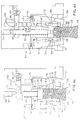
- the slide shaft aperture 94 includes an upwardly biasing means which spring member 165 contained in the distal portion of the slide shaft aperture 94.
- the aperture defines a retaining wall 167 which allows the slide shaft 92 to freely slide but which provides a stop for the spring 87 to cause the forward bias of the slide shaft 92.
- the slide member 81 includes a sized portion 169 on its lower periphery which is sized to accept a slide clamp 109. Additionally, extending upwardly from the sized portion is a incline portion 171 which guides the slide clamp 109 into the sized portion 169.
- the slide rail 83 includes a stepped portion 173 best seen in Figure 6f.
- the slide rail stepped portion 173 acts in conjunction with the slide member 81 to retain the slide member 81 in the rearwardly biased or loaded position.
- a slide clamp 109 In order for the slide member 81 to become fully outwardly extended or unloaded, it is necessary for a slide clamp 109 to be inserted into the device which causes the sliding member 81 to move upwardly which allows the slide member 81 to extend past the stepped portion 173 and become unloaded.
- the amount of play between the fully inserted position of the slide member 81 and the position of the slide member 81 when caught on the slide rail 83 stepped portion 173 is about equivalent to the amount of play allowed by the tapered slide latch 98.
- Figure 6a when the door 36 has been closed without the presence of a slide clamp 109, thereby activating the release pin 63, the slide member 81 initially attempts to bias forward but is retained by the slide rail stepped portion 173. This is to be contrasted with Figure 6f, in which the slide member 81 is retained by the slide latch 98 when the slide clamp 109 is inserted and the release pin 63 has not been activated.
- a rotary-type peristaltic pump can be used.
Abstract
Description
The peristaltic pumping action can also be applied on any point on the I.V. tubing.
The biasing means is a
Claims (10)
- A slide clamp (109) for selectively occluding and not occluding a flow lumen (24) of an I.V. tube (26), the slide clamp comprising:-characterised in that each of said opposite surfaces extends in a straight line from the occluding slot (111) to said end surface.a body having oppositely facing top and bottom surfaces (127,128);a regulating passage (110) defining an occluding slot (111) and a non-occluding passage (112), so that the clamp can be slid, relative to an I.V. tube (26) extending through the aperture, transverse to the length of the I.V. tube from a non-occluding position in which the tube is in the non-occluding passage to an occluding position in which the tube is in the occluding slot, so that the lumen of the I.V. tube may be selectively occluded or not occluded;the non-occluding passage (112) having opposite surfaces diverging from the occluding slot (111) and leading to an end surface opposite to the occluding slot;an access slit (113) in said end surface allowing the I.V. tube (26) to be positioned in the regulating aperture (110);the end surface having a projection (114) at each side of the access slit (113) and extending inwardly into the non-occluding passage (112) for resisting sliding of the slide clamp solely by force of gravity lengthwise of an I.V. tube (26) in the non-occluding passage (112), but permitting such movement upon application of a predetermined force greater than the force of gravity;
- The slide clamp of Claim 1 further comprising means (125) on the slide clamp for facilitating automated identification of the clamp.
- The slide clamp of Claim 2 wherein the automated identification means (125) comprises a surface portion, the surface portion reflecting a selected portion (206) of a beam of light (204) shined thereon, whereby an optical sensor (200,202) receiving the reflected beam can identify the slide clamp.
- The clamp of Claim 3 in combination with an optical sensor (200,202) comprising;a lamp (200) for omitting a selected beam of light (204), the beam of light being directed onto the surface portion (125), the surface pad absorbing a portion of the beam of light and reflecting a selected portion (206) of the beam of light;an optical sensor (202) for receiving the reflected selected portion (206) of the beam of light, the optical sensor being in a first state in response to receiving the selected portion of the beam of light and a second state in response to not receiving the selected portion of a beam of light; andmeans (202) operatively associated with the optical sensor for indicating the optical sensor being in the first or the second state.
- The slide clamp of any preceding claim in combination with a safety apparatus for a pump (20), the safety apparatus comprising a clamp receiving area (62) and means (81) within the clamp receiving area for selectively sliding the slide clamp relative to an I.V. tube (26) in the operative position between the occluding slot (111), and the non occluding passage (112)
- The combination of Claim 5, including a pump (20), a non-obstructive sensor (85) within the clamp receiving area (62), the non-obstructive sensor being in a first state in response to the presence of the clamp in a selected position in the slide clamp receiving area and a second state in response to the absence of the slide clamp from the selected position; and
means operatively associated with the non-obstructive sensor for disabling the pump (20) in response to the non-obstructive sensor being in the second state. - The combination of Claim 6 wherein the non-obstructive sensor comprises an electric eye (85).
- The combination of Claim 5 or 6 wherein the non-obstructive sensor (85) comprises:a pad (125) on the clamp (109,109') for reflecting a selected potion (206) of a beam of light (204);a light source (200) in the clamp receiving area (62) directing a beam of light (204) onto the pad (125); andan optical sensor (202) for receiving the selected portion (206) of the beam of light (204) reflected off the pad (125), the optical sensor (202) being in a first state in response to receiving the selected portion of a beam of light and a second state in response to not receiving the selected portion of a beam of light.
- The combination of Claim 5, 6 or 7, wherein the non-obstructive sensor (85) further comprises means for determining compatibility of the slide clamp with the sensor, the non-obstructive sensor being in a first state when the clamp is compatible with the safety apparatus and a second state when the clamp is not compatible with the safety apparatus.
- The combination of any one of Claims 5 to 8, wherein the pump comprises a peristaltic pump (20).
Applications Claiming Priority (7)
| Application Number | Priority Date | Filing Date | Title |
|---|---|---|---|
| US76575591A | 1991-09-26 | 1991-09-26 | |
| US765755 | 1991-09-26 | ||
| US07/884,498 US5290239A (en) | 1991-09-26 | 1992-05-15 | Intravenous tube safety apparatus |
| US884498 | 1992-05-15 | ||
| EP92921177A EP0563351B1 (en) | 1991-09-26 | 1992-09-25 | Intravenous tube safety apparatus |
| PCT/US1992/008212 WO1993005829A1 (en) | 1991-09-26 | 1992-09-25 | Intravenous tube safety apparatus |
| EP96200502A EP0718006B1 (en) | 1991-09-26 | 1992-09-25 | Intravenous tube slide clamp with sliding preventor |
Related Parent Applications (1)
| Application Number | Title | Priority Date | Filing Date |
|---|---|---|---|
| EP96200502A Division EP0718006B1 (en) | 1991-09-26 | 1992-09-25 | Intravenous tube slide clamp with sliding preventor |
Publications (3)
| Publication Number | Publication Date |
|---|---|
| EP0876825A2 true EP0876825A2 (en) | 1998-11-11 |
| EP0876825A3 EP0876825A3 (en) | 1999-10-20 |
| EP0876825B1 EP0876825B1 (en) | 2005-02-23 |
Family
ID=27117646
Family Applications (5)
| Application Number | Title | Priority Date | Filing Date |
|---|---|---|---|
| EP96200502A Expired - Lifetime EP0718006B1 (en) | 1991-09-26 | 1992-09-25 | Intravenous tube slide clamp with sliding preventor |
| EP98202761A Expired - Lifetime EP0876825B1 (en) | 1991-09-26 | 1992-09-25 | Intravenous tube slide clamp with sliding preventor |
| EP96200503A Expired - Lifetime EP0718007B1 (en) | 1991-09-26 | 1992-09-25 | Intravenous tube slide clamp with sliding friction minimizer |
| EP96200504A Expired - Lifetime EP0718008B2 (en) | 1991-09-26 | 1992-09-25 | IV pump safety apparatus with a non-obstructive clamp sensor |
| EP92921177A Expired - Lifetime EP0563351B1 (en) | 1991-09-26 | 1992-09-25 | Intravenous tube safety apparatus |
Family Applications Before (1)
| Application Number | Title | Priority Date | Filing Date |
|---|---|---|---|
| EP96200502A Expired - Lifetime EP0718006B1 (en) | 1991-09-26 | 1992-09-25 | Intravenous tube slide clamp with sliding preventor |
Family Applications After (3)
| Application Number | Title | Priority Date | Filing Date |
|---|---|---|---|
| EP96200503A Expired - Lifetime EP0718007B1 (en) | 1991-09-26 | 1992-09-25 | Intravenous tube slide clamp with sliding friction minimizer |
| EP96200504A Expired - Lifetime EP0718008B2 (en) | 1991-09-26 | 1992-09-25 | IV pump safety apparatus with a non-obstructive clamp sensor |
| EP92921177A Expired - Lifetime EP0563351B1 (en) | 1991-09-26 | 1992-09-25 | Intravenous tube safety apparatus |
Country Status (7)
| Country | Link |
|---|---|
| US (2) | US5290239A (en) |
| EP (5) | EP0718006B1 (en) |
| JP (2) | JP3508024B2 (en) |
| AU (2) | AU656035B2 (en) |
| CA (4) | CA2201532C (en) |
| DE (5) | DE69223397T2 (en) |
| WO (1) | WO1993005829A1 (en) |
Cited By (1)
| Publication number | Priority date | Publication date | Assignee | Title |
|---|---|---|---|---|
| US8052643B2 (en) | 2006-03-02 | 2011-11-08 | Tyco Healthcare Group Lp | Enteral feeding set and interlock device therefor |
Families Citing this family (123)
| Publication number | Priority date | Publication date | Assignee | Title |
|---|---|---|---|---|
| US5772637A (en) * | 1995-06-07 | 1998-06-30 | Deka Products Limited Partnership | Intravenous-line flow-control system |
| US5853397A (en) * | 1993-12-13 | 1998-12-29 | Migada, Inc. | Medical infusion apparatus including safety valve |
| US5401256A (en) * | 1994-01-14 | 1995-03-28 | Minnesota Mining And Manufacturing Company | Flexible clamp for use in IV tubing set |
| US5562615A (en) * | 1994-02-28 | 1996-10-08 | Corpak, Inc. | Free flow detector for an enternal feeding pump |
| US5658133A (en) * | 1994-03-09 | 1997-08-19 | Baxter International Inc. | Pump chamber back pressure dissipation apparatus and method |
| US5482446A (en) * | 1994-03-09 | 1996-01-09 | Baxter International Inc. | Ambulatory infusion pump |
| US5453098A (en) * | 1994-05-09 | 1995-09-26 | Imed Corporation | Two step IV fluid flow stop |
| US5601420A (en) * | 1994-09-12 | 1997-02-11 | Ivac Medical Systems, Inc. | Interlock, latching, and retaining mechanism for an infusion pump |
| US5505709A (en) * | 1994-09-15 | 1996-04-09 | Minimed, Inc., A Delaware Corporation | Mated infusion pump and syringe |
| US5567120A (en) * | 1994-10-13 | 1996-10-22 | Sigma International | Electronic infusion device and novel roller clamp holden therefor |
| US5904668A (en) | 1995-03-06 | 1999-05-18 | Sabratek Corporation | Cassette for an infusion pump |
| GB2305370B (en) * | 1995-09-19 | 1997-10-29 | Asahi Medical Co | Device for depletion of leukocytes |
| US5967484A (en) * | 1995-12-21 | 1999-10-19 | Alaris Medical Systems, Inc. | Intravenous tube occluder |
| US5954313A (en) * | 1995-12-29 | 1999-09-21 | Rymed Technologies, Inc. | Medical intravenous administration line connectors having a luer activated valve |
| US5788215A (en) * | 1995-12-29 | 1998-08-04 | Rymed Technologies | Medical intravenous administration line connectors having a luer or pressure activated valve |
| US5833213A (en) * | 1995-12-29 | 1998-11-10 | Rymed Technologies, Inc. | Multiple dose drug vial adapter for use with a vial having a pierceable septum and a needleless syringe |
| GB2338752B (en) * | 1996-04-10 | 2000-07-19 | Baxter Int | Volumetric infusion pump |
| AU728493B2 (en) * | 1996-04-10 | 2001-01-11 | Baxter International Inc. | An infusion pump with a shuttle for deforming and reforming a tube |
| GB9607471D0 (en) * | 1996-04-10 | 1996-06-12 | Baxter Int | Volumetric infusion pump |
| AU736366B2 (en) * | 1996-04-10 | 2001-07-26 | Baxter International Inc. | Automatic loading apparatus for volumetric infusion pump |
| AU725739B2 (en) * | 1996-04-10 | 2000-10-19 | Baxter International Inc. | Method of detecting a misload of a tube into a volumetric infusion pump |
| FR2748310A1 (en) * | 1996-05-03 | 1997-11-07 | Debiotech Sa | DEVICE FOR CLOSING A FLEXIBLE TUBE |
| US5853386A (en) | 1996-07-25 | 1998-12-29 | Alaris Medical Systems, Inc. | Infusion device with disposable elements |
| US6702789B1 (en) | 1997-03-11 | 2004-03-09 | Alcove Medical, Inc. | Catheter having insertion control mechanism and anti-bunching mechanism |
| US6261262B1 (en) | 1997-06-12 | 2001-07-17 | Abbott Laboratories | Pump with anti-free flow feature |
| US6877713B1 (en) * | 1999-07-20 | 2005-04-12 | Deka Products Limited Partnership | Tube occluder and method for occluding collapsible tubes |
| DE19944343A1 (en) | 1999-09-16 | 2001-04-12 | Fresenius Ag | Valve |
| US6592519B1 (en) | 2000-04-28 | 2003-07-15 | Medtronic, Inc. | Smart microfluidic device with universal coating |
| WO2003006101A2 (en) * | 2001-07-10 | 2003-01-23 | Medrad, Inc. | Devices, systems and method for infusion of fluids |
| US6722865B2 (en) | 2001-09-07 | 2004-04-20 | Terumorcardiovascular Systems Corporation | Universal tube clamp assembly |
| WO2003041787A2 (en) * | 2001-11-15 | 2003-05-22 | Arcomed Ag | Safety device for an infusion pump |
| ITMI20020359A1 (en) | 2002-02-22 | 2003-08-22 | Gambro Lundia Ab | METHOD OF CONTROL OF THE OPERATION OF A FLOW INTERDICTION BODY AND A FLOW STOP DEVICE FOR AN EXTRA-BODY CIRCUIT |
| US7018361B2 (en) * | 2002-06-14 | 2006-03-28 | Baxter International Inc. | Infusion pump |
| US7553295B2 (en) | 2002-06-17 | 2009-06-30 | Iradimed Corporation | Liquid infusion apparatus |
| US7267661B2 (en) | 2002-06-17 | 2007-09-11 | Iradimed Corporation | Non-magnetic medical infusion device |
| SE526008C2 (en) | 2002-10-10 | 2005-06-14 | Medical Vision Res & Dev Ab | Medical-technical identification device |
| US20040088189A1 (en) * | 2002-11-06 | 2004-05-06 | Veome Edmond A. | System and method for monitoring , reporting, managing and administering the treatment of a blood component |
| DE10312272A1 (en) * | 2003-03-19 | 2004-09-30 | Justus-Liebig-Universität Giessen | Test device for determining cerebral auto-regulative capacity of higher mammals, has one closure element which opens and closes in antiphase with other closure element |
| IL157981A (en) | 2003-09-17 | 2014-01-30 | Elcam Medical Agricultural Cooperative Ass Ltd | Auto-injector |
| US6840492B1 (en) | 2003-11-21 | 2005-01-11 | Alaris Medical Systems, Inc. | Slide clamp |
| IL160891A0 (en) | 2004-03-16 | 2004-08-31 | Auto-mix needle | |
| US7927313B2 (en) * | 2004-05-27 | 2011-04-19 | Baxter International Inc. | Medical device configuration based on recognition of identification information |
| US20050277873A1 (en) * | 2004-05-27 | 2005-12-15 | Janice Stewart | Identification information recognition system for a medical device |
| JP4754917B2 (en) * | 2004-10-19 | 2011-08-24 | テルモ株式会社 | Infusion device |
| US7976518B2 (en) | 2005-01-13 | 2011-07-12 | Corpak Medsystems, Inc. | Tubing assembly and signal generator placement control device and method for use with catheter guidance systems |
| WO2006083933A1 (en) * | 2005-02-01 | 2006-08-10 | Baxter International Inc. | Infusion delivery system |
| US20060264935A1 (en) * | 2005-05-04 | 2006-11-23 | White Patrick M | Orthopedic stabilization device |
| US7846131B2 (en) | 2005-09-30 | 2010-12-07 | Covidien Ag | Administration feeding set and flow control apparatus with secure loading features |
| US20070095941A1 (en) * | 2005-11-03 | 2007-05-03 | Gorres Geoffrey H | Scent dispensing apparatus |
| US7722573B2 (en) | 2006-03-02 | 2010-05-25 | Covidien Ag | Pumping apparatus with secure loading features |
| US7758551B2 (en) | 2006-03-02 | 2010-07-20 | Covidien Ag | Pump set with secure loading features |
| US7722562B2 (en) | 2006-03-02 | 2010-05-25 | Tyco Healthcare Group Lp | Pump set with safety interlock |
| US7763005B2 (en) | 2006-03-02 | 2010-07-27 | Covidien Ag | Method for using a pump set having secure loading features |
| US8021336B2 (en) | 2007-01-05 | 2011-09-20 | Tyco Healthcare Group Lp | Pump set for administering fluid with secure loading features and manufacture of component therefor |
| US10537671B2 (en) | 2006-04-14 | 2020-01-21 | Deka Products Limited Partnership | Automated control mechanisms in a hemodialysis apparatus |
| CA2970214C (en) | 2006-04-14 | 2021-08-17 | Deka Products Limited Partnership | System for pumping a biological fluid |
| US7611498B2 (en) * | 2006-05-18 | 2009-11-03 | Codan Holding Gmbh | Arrangement for the coupling of an intravenous tube with infusion pump |
| FR2908176B1 (en) | 2006-11-08 | 2008-12-19 | Fresenius Vial Soc Par Actions | DEVICE FOR MONITORING THE OPENING OR CLOSING OF A CLAMP IN A VOLUMETRIC PUMP |
| US7560686B2 (en) | 2006-12-11 | 2009-07-14 | Tyco Healthcare Group Lp | Pump set and pump with electromagnetic radiation operated interlock |
| CA2673517C (en) | 2006-12-22 | 2014-07-22 | Mondiale Technologies Limited | Flow controller |
| US8888470B2 (en) * | 2007-02-27 | 2014-11-18 | Deka Products Limited Partnership | Pumping cassette |
| US9517295B2 (en) | 2007-02-27 | 2016-12-13 | Deka Products Limited Partnership | Blood treatment systems and methods |
| KR20230165373A (en) * | 2007-02-27 | 2023-12-05 | 데카 프로덕츠 리미티드 파트너쉽 | Hemodialysis system |
| US8393690B2 (en) | 2007-02-27 | 2013-03-12 | Deka Products Limited Partnership | Enclosure for a portable hemodialysis system |
| US20090107335A1 (en) | 2007-02-27 | 2009-04-30 | Deka Products Limited Partnership | Air trap for a medical infusion device |
| US8357298B2 (en) | 2007-02-27 | 2013-01-22 | Deka Products Limited Partnership | Hemodialysis systems and methods |
| US9028691B2 (en) | 2007-02-27 | 2015-05-12 | Deka Products Limited Partnership | Blood circuit assembly for a hemodialysis system |
| US8425471B2 (en) | 2007-02-27 | 2013-04-23 | Deka Products Limited Partnership | Reagent supply for a hemodialysis system |
| US8562834B2 (en) | 2007-02-27 | 2013-10-22 | Deka Products Limited Partnership | Modular assembly for a portable hemodialysis system |
| US8042563B2 (en) | 2007-02-27 | 2011-10-25 | Deka Products Limited Partnership | Cassette system integrated apparatus |
| US8409441B2 (en) | 2007-02-27 | 2013-04-02 | Deka Products Limited Partnership | Blood treatment systems and methods |
| US8491184B2 (en) | 2007-02-27 | 2013-07-23 | Deka Products Limited Partnership | Sensor apparatus systems, devices and methods |
| US8025645B2 (en) | 2007-05-25 | 2011-09-27 | Medical Components, Inc. | Guard for flexible tubing clamp and method of using same |
| US8105282B2 (en) | 2007-07-13 | 2012-01-31 | Iradimed Corporation | System and method for communication with an infusion device |
| US8062008B2 (en) * | 2007-09-27 | 2011-11-22 | Curlin Medical Inc. | Peristaltic pump and removable cassette therefor |
| EP2246080B1 (en) * | 2007-10-12 | 2016-02-10 | DEKA Products Limited Partnership | An extracorporeal blood flow system |
| US8771508B2 (en) * | 2008-08-27 | 2014-07-08 | Deka Products Limited Partnership | Dialyzer cartridge mounting arrangement for a hemodialysis system |
| US8863772B2 (en) * | 2008-08-27 | 2014-10-21 | Deka Products Limited Partnership | Occluder for a medical infusion system |
| EP3594959A1 (en) | 2008-01-23 | 2020-01-15 | DEKA Products Limited Partnership | Medical treatment system and methods using a plurality of fluid lines |
| US7762989B2 (en) * | 2008-02-08 | 2010-07-27 | Baxter International Inc. | Method and apparatus for preventing the use of unauthorized disposable sets in infusion pumps |
| AU2009231734B2 (en) * | 2008-04-01 | 2014-08-28 | Zevex, Inc. | Anti-free flow mechanism for enteral feeding pumps |
| CA2720492C (en) * | 2008-04-01 | 2017-07-25 | Zevex, Inc. | Safety occluder and method of use |
| US7717900B2 (en) | 2008-05-28 | 2010-05-18 | Angio Dynamics, Inc. | Locking clamp |
| US8105269B2 (en) | 2008-10-24 | 2012-01-31 | Baxter International Inc. | In situ tubing measurements for infusion pumps |
| WO2010101783A2 (en) * | 2009-03-06 | 2010-09-10 | Deka Products Limited Partnership | Devices and methods for occluding a flexible tube |
| US8137083B2 (en) | 2009-03-11 | 2012-03-20 | Baxter International Inc. | Infusion pump actuators, system and method for controlling medical fluid flowrate |
| CN104873389B (en) | 2009-07-29 | 2017-12-05 | Icu医学有限公司 | Fluid conveying device and application method |
| EP3072545B1 (en) | 2009-10-30 | 2019-05-08 | DEKA Products Limited Partnership | Apparatus for detecting disconnection of an intravascular access device |
| US8382447B2 (en) | 2009-12-31 | 2013-02-26 | Baxter International, Inc. | Shuttle pump with controlled geometry |
| US8154274B2 (en) | 2010-05-11 | 2012-04-10 | Tyco Healthcare Group Lp | Safety interlock |
| US8567235B2 (en) | 2010-06-29 | 2013-10-29 | Baxter International Inc. | Tube measurement technique using linear actuator and pressure sensor |
| US8465464B2 (en) | 2010-08-06 | 2013-06-18 | WalkMed Infusion LLC | Infusion pump and slide clamp apparatus and method |
| US9017297B2 (en) | 2010-08-06 | 2015-04-28 | WalkMed Infusion LLC | Infusion pump and method which inhibits unintended tubing withdrawal |
| US8469933B2 (en) | 2011-03-18 | 2013-06-25 | Zyno Medical Llc | Pump activated pinch clamp |
| SG10201604142SA (en) | 2011-05-24 | 2016-07-28 | Deka Products Lp | Hemodialysis System |
| US9028441B2 (en) | 2011-09-08 | 2015-05-12 | Corpak Medsystems, Inc. | Apparatus and method used with guidance system for feeding and suctioning |
| CN103930160B (en) * | 2011-11-16 | 2017-05-03 | 费森尤斯维亚尔两合公司 | Tube pump, tube clamp, perfusion set and system comprising a tube pump and a tube clamp |
| US9050447B2 (en) | 2011-11-23 | 2015-06-09 | Carefusion 303, Inc. | Positive bolus clamp |
| CA3075368C (en) | 2011-12-22 | 2023-07-11 | Icu Medical, Inc. | Fluid transfer devices and methods of use |
| US9364655B2 (en) * | 2012-05-24 | 2016-06-14 | Deka Products Limited Partnership | Flexible tubing occlusion assembly |
| WO2014036325A2 (en) | 2012-08-30 | 2014-03-06 | C.R. Bard, Inc. | Tubing clamp |
| US20150133861A1 (en) | 2013-11-11 | 2015-05-14 | Kevin P. McLennan | Thermal management system and method for medical devices |
| EP3073982B1 (en) | 2013-11-25 | 2020-04-08 | ICU Medical, Inc. | Methods and system for filling iv bags with therapeutic fluid |
| US10143795B2 (en) | 2014-08-18 | 2018-12-04 | Icu Medical, Inc. | Intravenous pole integrated power, control, and communication system and method for an infusion pump |
| AU2016267763B2 (en) | 2015-05-26 | 2021-07-08 | Icu Medical, Inc. | Disposable infusion fluid delivery device for programmable large volume drug delivery |
| WO2016196102A1 (en) * | 2015-06-01 | 2016-12-08 | Smiths Medical Asd, Inc. | Infusate tubing clamp systems for infusion pumps |
| JP6710758B2 (en) | 2015-12-04 | 2020-06-17 | アイシーユー・メディカル・インコーポレーテッド | Electronic medical fluid transfer device for transferring medical fluid |
| US10167861B2 (en) * | 2016-05-26 | 2019-01-01 | Namiki Precision Singapore Pte. Ltd. | Infusion pump |
| USD851745S1 (en) | 2016-07-19 | 2019-06-18 | Icu Medical, Inc. | Medical fluid transfer system |
| JP7046051B2 (en) | 2016-07-25 | 2022-04-01 | アイシーユー・メディカル・インコーポレーテッド | Systems and components for trapping air bubbles in medical fluid transfer modules and systems |
| CN106039473A (en) * | 2016-07-26 | 2016-10-26 | 刘晓琳 | Novel gravity venous transfusion nursing management apparatus |
| DE102017115862A1 (en) * | 2017-07-14 | 2019-01-17 | B. Braun Melsungen Ag | Device for controlling the opening and closing of a hose |
| US11268506B2 (en) | 2017-12-22 | 2022-03-08 | Iradimed Corporation | Fluid pumps for use in MRI environment |
| TWI674122B (en) * | 2018-06-14 | 2019-10-11 | 英華達股份有限公司 | Infusion equipment |
| EP3806928A1 (en) * | 2018-06-18 | 2021-04-21 | Fresenius Vial SAS | Infusion device comprising a clamping mechanism |
| CN108628353B (en) * | 2018-06-29 | 2024-02-06 | 中国电建集团中南勘测设计研究院有限公司 | Pool water level control device |
| USD917045S1 (en) | 2018-08-16 | 2021-04-20 | Deka Products Limited Partnership | Slide clamp |
| US10808689B2 (en) | 2018-12-17 | 2020-10-20 | Curlin Medical Inc. | Peristaltic pump having improved pumping fingers |
| USD1004412S1 (en) | 2019-08-16 | 2023-11-14 | Deka Products Limited Partnership | Slide clamp assembly |
| USD939079S1 (en) | 2019-08-22 | 2021-12-21 | Icu Medical, Inc. | Infusion pump |
| US11202859B2 (en) * | 2019-11-20 | 2021-12-21 | B Braun Medical Inc. | Cassette with free flow prevention for infusion pump |
| US11590057B2 (en) | 2020-04-03 | 2023-02-28 | Icu Medical, Inc. | Systems, methods, and components for transferring medical fluids |
| DE102021215067A1 (en) * | 2021-12-28 | 2023-06-29 | B. Braun Melsungen Aktiengesellschaft | IV Systems - Infusion pump for detecting the color of a hose clamp with IR markers |
Citations (10)
| Publication number | Priority date | Publication date | Assignee | Title |
|---|---|---|---|---|
| US2889848A (en) * | 1955-12-22 | 1959-06-09 | Redmer Sons Company | Flow control clamp |
| US3374509A (en) * | 1966-05-27 | 1968-03-26 | Bard Inc C R | Clamp |
| US4248401A (en) * | 1979-05-07 | 1981-02-03 | Baxter Travenol Laboratories, Inc. | Plastic slide clamp for tubing |
| US4307869A (en) * | 1980-12-15 | 1981-12-29 | Baxter Travenol Laboratories, Inc. | One way slide clamp for tubing |
| US4434963A (en) * | 1982-12-22 | 1984-03-06 | Baxter Travenol Laboratories, Inc. | Slide clamp including elevation stabilizer |
| US4460358A (en) * | 1980-11-07 | 1984-07-17 | Ivac Corporation | Combined load and latch mechanism for fluid flow control apparatus |
| US4637817A (en) * | 1984-11-29 | 1987-01-20 | Minnesota Mining & Manufacturing Company | Sequence valve for piggyback IV administration with occlusion failure sensing |
| US4689043A (en) * | 1986-03-19 | 1987-08-25 | Imed Corporation | IV tube activator |
| EP0319279A1 (en) * | 1987-12-01 | 1989-06-07 | PACESETTER INFUSION LTD. trading as MINIMED TECHNOLOGIES | Cassette loading and latching apparatus for a medication infusion system |
| US5017192A (en) * | 1989-10-20 | 1991-05-21 | Minnesota Mining And Manufacturing Company | Free flow prevention system for infusion pump |
Family Cites Families (28)
| Publication number | Priority date | Publication date | Assignee | Title |
|---|---|---|---|---|
| US2092400A (en) * | 1935-07-01 | 1937-09-07 | Faultless Rubber Co | Valve means |
| US2503327A (en) * | 1947-05-07 | 1950-04-11 | Abbott Lab | Pinchcock |
| US2775240A (en) * | 1953-02-09 | 1956-12-25 | Abbott Lab | Gas valve |
| US2715905A (en) * | 1953-11-16 | 1955-08-23 | Robert W Ogle | Intravenous injection set |
| US3167299A (en) * | 1961-01-05 | 1965-01-26 | Abbott Lab | Flow regulating device |
| US3357674A (en) * | 1963-07-01 | 1967-12-12 | Pharmaseal Lab | Tubing clamp |
| US3316935A (en) * | 1964-06-24 | 1967-05-02 | Abbott Lab | Flow control clamp |
| US3612475A (en) * | 1969-04-02 | 1971-10-12 | Amp Inc | Flexible tube closure |
| US3994294A (en) * | 1975-02-28 | 1976-11-30 | Ivac Corporation | Syringe pump valving and motor direction control system |
| FR2331088A1 (en) * | 1975-11-05 | 1977-06-03 | Clin Midy | FLOW REGULATOR ESPECIALLY FOR INFUSION |
| US4155362A (en) * | 1976-01-26 | 1979-05-22 | Baxter Travenol Laboratories, Inc. | Method and apparatus for metered infusion of fluids |
| US4367736A (en) * | 1980-08-25 | 1983-01-11 | Baxter Travenol Laboratories, Inc. | System for detecting bubble formation in clear and opaque fluids |
| US4416595A (en) * | 1981-03-13 | 1983-11-22 | Baxter Travenol Laboratories, Inc. | Miniature rotary infusion pump with slide latch and detachable power source |
| US4439179A (en) * | 1982-02-16 | 1984-03-27 | Baxter Travenol Laboratories, Inc. | Dual tubing clamp |
| US4993456A (en) * | 1982-03-02 | 1991-02-19 | Akos Sule | Pinch valve assembly |
| US4519792A (en) * | 1982-12-06 | 1985-05-28 | Abbott Laboratories | Infusion pump system |
| US4533347A (en) * | 1983-12-19 | 1985-08-06 | Warner-Lambert Company | Controller for a dual drug delivery system |
| US4585441A (en) * | 1984-09-17 | 1986-04-29 | Minnesota Mining And Manufacturing Company | IV fluid control system with fluid runaway prevention |
| US4524802A (en) * | 1984-10-01 | 1985-06-25 | Bio-Chem Valve Corp. | Pinch valve |
| US4565542A (en) * | 1984-10-19 | 1986-01-21 | Deltec Systems, Inc. | Locking mechanism for a drug delivery system |
| US4586691A (en) * | 1985-05-13 | 1986-05-06 | Warner-Lambert Company | Safety slide clamp |
| US4857050A (en) * | 1987-09-23 | 1989-08-15 | Fisher Scientific Company | Ratiometric air-in-line detector |
| ES2064370T3 (en) * | 1988-01-21 | 1995-02-01 | Hubner Karl Alexander | DEVICE FOR CLOSING FLEXIBLE PLASTIC TUBES, IN PARTICULAR INFUSION TUBES, FOR AIR TRAPS. |
| US5009641A (en) * | 1988-12-02 | 1991-04-23 | Pacesetter Infusion, Ltd. | Patient-controlled analgesia security attachment for a medication infusion system |
| US4978335A (en) * | 1989-09-29 | 1990-12-18 | Medex, Inc. | Infusion pump with bar code input to computer |
| US5039279A (en) * | 1990-03-15 | 1991-08-13 | Abbott Laboratories | Sensor for detecting fluid flow from a positive displacement pump |
| JPH0693916B2 (en) * | 1990-10-31 | 1994-11-24 | テルモ株式会社 | Infusion pump |
| US5221268A (en) * | 1991-12-06 | 1993-06-22 | Block Medical, Inc. | Multiple dose control apparatus |
-
1992
- 1992-05-15 US US07/884,498 patent/US5290239A/en not_active Expired - Lifetime
- 1992-09-25 CA CA002201532A patent/CA2201532C/en not_active Expired - Fee Related
- 1992-09-25 DE DE69223397T patent/DE69223397T2/en not_active Expired - Lifetime
- 1992-09-25 CA CA002098402A patent/CA2098402C/en not_active Expired - Fee Related
- 1992-09-25 DE DE69233483T patent/DE69233483T2/en not_active Expired - Lifetime
- 1992-09-25 DE DE69225618T patent/DE69225618T3/en not_active Expired - Lifetime
- 1992-09-25 EP EP96200502A patent/EP0718006B1/en not_active Expired - Lifetime
- 1992-09-25 EP EP98202761A patent/EP0876825B1/en not_active Expired - Lifetime
- 1992-09-25 CA CA002201531A patent/CA2201531C/en not_active Expired - Fee Related
- 1992-09-25 EP EP96200503A patent/EP0718007B1/en not_active Expired - Lifetime
- 1992-09-25 WO PCT/US1992/008212 patent/WO1993005829A1/en active IP Right Grant
- 1992-09-25 EP EP96200504A patent/EP0718008B2/en not_active Expired - Lifetime
- 1992-09-25 EP EP92921177A patent/EP0563351B1/en not_active Expired - Lifetime
- 1992-09-25 DE DE69228569T patent/DE69228569T2/en not_active Expired - Lifetime
- 1992-09-25 DE DE69226663T patent/DE69226663T2/en not_active Expired - Lifetime
- 1992-09-25 CA CA002095857A patent/CA2095857C/en not_active Expired - Fee Related
- 1992-09-25 JP JP50640293A patent/JP3508024B2/en not_active Expired - Fee Related
- 1992-09-25 AU AU27578/92A patent/AU656035B2/en not_active Ceased
-
1993
- 1993-04-12 US US08/045,291 patent/US5300044A/en not_active Expired - Lifetime
-
1994
- 1994-11-01 AU AU77543/94A patent/AU667447B2/en not_active Ceased
-
2002
- 2002-08-14 JP JP2002236163A patent/JP2003062069A/en active Pending
Patent Citations (10)
| Publication number | Priority date | Publication date | Assignee | Title |
|---|---|---|---|---|
| US2889848A (en) * | 1955-12-22 | 1959-06-09 | Redmer Sons Company | Flow control clamp |
| US3374509A (en) * | 1966-05-27 | 1968-03-26 | Bard Inc C R | Clamp |
| US4248401A (en) * | 1979-05-07 | 1981-02-03 | Baxter Travenol Laboratories, Inc. | Plastic slide clamp for tubing |
| US4460358A (en) * | 1980-11-07 | 1984-07-17 | Ivac Corporation | Combined load and latch mechanism for fluid flow control apparatus |
| US4307869A (en) * | 1980-12-15 | 1981-12-29 | Baxter Travenol Laboratories, Inc. | One way slide clamp for tubing |
| US4434963A (en) * | 1982-12-22 | 1984-03-06 | Baxter Travenol Laboratories, Inc. | Slide clamp including elevation stabilizer |
| US4637817A (en) * | 1984-11-29 | 1987-01-20 | Minnesota Mining & Manufacturing Company | Sequence valve for piggyback IV administration with occlusion failure sensing |
| US4689043A (en) * | 1986-03-19 | 1987-08-25 | Imed Corporation | IV tube activator |
| EP0319279A1 (en) * | 1987-12-01 | 1989-06-07 | PACESETTER INFUSION LTD. trading as MINIMED TECHNOLOGIES | Cassette loading and latching apparatus for a medication infusion system |
| US5017192A (en) * | 1989-10-20 | 1991-05-21 | Minnesota Mining And Manufacturing Company | Free flow prevention system for infusion pump |
Cited By (1)
| Publication number | Priority date | Publication date | Assignee | Title |
|---|---|---|---|---|
| US8052643B2 (en) | 2006-03-02 | 2011-11-08 | Tyco Healthcare Group Lp | Enteral feeding set and interlock device therefor |
Also Published As
Similar Documents
| Publication | Publication Date | Title |
|---|---|---|
| EP0876825B1 (en) | Intravenous tube slide clamp with sliding preventor | |
| CA2292602C (en) | Pump with anti-free flow feature | |
| US6635033B1 (en) | Medical tubing slide clamp device for determining proper tubing size and functional characteristics | |
| CA2629449C (en) | Automatic clamp apparatus | |
| US5257978A (en) | IV safety module | |
| US20040127860A1 (en) | Patient controlled drug administration device | |
| US5242407A (en) | Infusion pump with improved contamination resistance | |
| EP0781378B1 (en) | Fluid delivery system with mounting linkage | |
| JPH09262291A (en) | Clamp and method for blocking tube |
Legal Events
| Date | Code | Title | Description |
|---|---|---|---|
| PUAI | Public reference made under article 153(3) epc to a published international application that has entered the european phase |
Free format text: ORIGINAL CODE: 0009012 |
|
| 17P | Request for examination filed |
Effective date: 19980828 |
|
| AC | Divisional application: reference to earlier application |
Ref document number: 718006 Country of ref document: EP |
|
| AK | Designated contracting states |
Kind code of ref document: A2 Designated state(s): DE FR GB IT |
|
| RIN1 | Information on inventor provided before grant (corrected) |
Inventor name: VEHOVSKY, GABRIEL Inventor name: MCVEY, JOHN Inventor name: LYNN, KENNETH Inventor name: GRAJO, THERESA Inventor name: CLASSEY, DONALD J. Inventor name: MYREN, ERIC |
|
| PUAL | Search report despatched |
Free format text: ORIGINAL CODE: 0009013 |
|
| AK | Designated contracting states |
Kind code of ref document: A3 Designated state(s): DE FR GB IT |
|
| 17Q | First examination report despatched |
Effective date: 20020405 |
|
| GRAP | Despatch of communication of intention to grant a patent |
Free format text: ORIGINAL CODE: EPIDOSNIGR1 |
|
| GRAS | Grant fee paid |
Free format text: ORIGINAL CODE: EPIDOSNIGR3 |
|
| GRAA | (expected) grant |
Free format text: ORIGINAL CODE: 0009210 |
|
| AC | Divisional application: reference to earlier application |
Ref document number: 0563351 Country of ref document: EP Kind code of ref document: P Ref document number: 0718006 Country of ref document: EP Kind code of ref document: P |
|
| AK | Designated contracting states |
Kind code of ref document: B1 Designated state(s): DE FR GB IT |
|
| REG | Reference to a national code |
Ref country code: GB Ref legal event code: FG4D |
|
| REF | Corresponds to: |
Ref document number: 69233483 Country of ref document: DE Date of ref document: 20050331 Kind code of ref document: P |
|
| ET | Fr: translation filed | ||
| PLBE | No opposition filed within time limit |
Free format text: ORIGINAL CODE: 0009261 |
|
| STAA | Information on the status of an ep patent application or granted ep patent |
Free format text: STATUS: NO OPPOSITION FILED WITHIN TIME LIMIT |
|
| 26N | No opposition filed |
Effective date: 20051124 |
|
| PGFP | Annual fee paid to national office [announced via postgrant information from national office to epo] |
Ref country code: GB Payment date: 20090929 Year of fee payment: 18 |
|
| PGFP | Annual fee paid to national office [announced via postgrant information from national office to epo] |
Ref country code: DE Payment date: 20090929 Year of fee payment: 18 |
|
| PGFP | Annual fee paid to national office [announced via postgrant information from national office to epo] |
Ref country code: IT Payment date: 20090929 Year of fee payment: 18 |
|
| GBPC | Gb: european patent ceased through non-payment of renewal fee |
Effective date: 20100925 |
|
| PG25 | Lapsed in a contracting state [announced via postgrant information from national office to epo] |
Ref country code: IT Free format text: LAPSE BECAUSE OF NON-PAYMENT OF DUE FEES Effective date: 20100925 |
|
| REG | Reference to a national code |
Ref country code: FR Ref legal event code: ST Effective date: 20110531 |
|
| REG | Reference to a national code |
Ref country code: DE Ref legal event code: R119 Ref document number: 69233483 Country of ref document: DE Effective date: 20110401 |
|
| PG25 | Lapsed in a contracting state [announced via postgrant information from national office to epo] |
Ref country code: FR Free format text: LAPSE BECAUSE OF NON-PAYMENT OF DUE FEES Effective date: 20100930 Ref country code: DE Free format text: LAPSE BECAUSE OF NON-PAYMENT OF DUE FEES Effective date: 20110401 |
|
| PG25 | Lapsed in a contracting state [announced via postgrant information from national office to epo] |
Ref country code: GB Free format text: LAPSE BECAUSE OF NON-PAYMENT OF DUE FEES Effective date: 20100925 |
|
| PGFP | Annual fee paid to national office [announced via postgrant information from national office to epo] |
Ref country code: FR Payment date: 20091006 Year of fee payment: 18 |