FIELD OF THE INVENTION
The present invention relates to a digital
broadcasting transmitting method, a digital
broadcasting transmitting apparatus, and a digital
broadcasting reproducing apparatus and, more
particularly to a digital broadcasting transmitting
method, a digital broadcasting transmitting apparatus,
and a digital broadcasting reproducing apparatus in a
digital broadcasting system wherein a transport stream
in which plural packets comprising packets of video
data of digitized video and packets of service
information about broadcasting of the video have been
multiplexed is transmitted over a network.
BACKGROUND OF THE INVENTION
Conventionally, in TV broadcasting or the like,
analog signals were transmitted and received. Recently,
much attention has been focused on digital broadcasting
in which video, audio, character or other data are
handled in the same manner.
Advantages of the digital broadcasting are as
follows. i) Since various types of data can be handled
collectedly, integration of services can be provided.
ii) A compression technique is employed to
transmit/receive data, thereby a great deal of
broadcasting of high quality can be performed with a
limited transmission bandwidth. iii) Uniform services
are offered to users by employing an error correcting
technique. iv) High techniques may be employed with
ease as an encryption technique for limited receiving.
In a case where the various types of data,
especially moving pictures of large volumes of data are
recorded, transmitted or received as digital data,
analog information of the moving pictures is generally
subjected to analog-to-digital conversion, and the
resulting digital data is compressively coded. There
has been proposed an MPEG standard (Moving Picture
Experts Group) of a moving picture compression
technique, which is widely available, and described in
LATEST MPEG TEXTBOOK
" published by ASCII Corp. August
1, 1994, and
PRACTICAL MPEG TEXTBOOK
" published by
ASCII Corp. November 1, 1995, a video data
transmitting/receiving method or a digital broadcasting
reproducing apparatus according to MPEG described in
these text books is well-known.
Generally, the digital data or compressively coded
data is transmitted/received in packeted form. A
packet is a unit of data in which entire data is
divided into given size data. Transmitting/receiving
data in packeted form allows higher efficiency and
precision in data communication. For example, in a
case where packet switching is performed over a
computer network, since packets are respectively sent
to transfer destination at different timings, where
they are restructured to be original data, information
about the transfer destination, transmitting end, or
order of packets is added to respective packets.
Thus, in communication systems such as the digital
communication system, by employing a packeting
technique, various data such as video, audio and
additional information are packeted and combined to
create multiplexed data, to be transmitted/received.
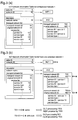
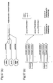
Figures 57(a) and 57(b) show a prior art digital
broadcasting system. As shown in figure 57(a), in a
transmitting end, various types of data is packeted and
then multiplexed, resulting in a transport stream to-be-transmitted.
As shown in figure 57(b), one or a plurality of
transport streams are transmitted over a network.
In general, each transport stream includes plural
services, namely,
PROGRAM
" which correspond to
channels in conventional analog TV broadcasting, and
each of the services includes one or a plurality of
events which correspond to programs. Thus, in the
digital TV broadcasting service, audio, video, and
additional information of plural channels can be
transmitted as multiplexed data. Viewers can utilize
the digital broadcasting by the use of receivers
adapted to the corresponding networks. Specifically,
networks 1 and 2 in figure 57(b) are supposed to be
used by receivers for them, respectively.
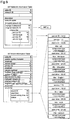
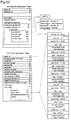
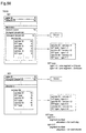
Figure 58 shows an NIT (Network Information Table),
an SDT (Service Description Table), and an EIT (Event
Information Table), which are used in the digital
broadcasting system. The NIT is information for each
network, and contains various types of information
about each network or information about a transport
stream which belongs to each network. The SDT is
information for each transport stream, and contains
various types of information about each transport
stream and information about a service which belongs to
each transport stream. The EIT is information for each
service, and contains various types of information
about each service and information about events which
belong to each service.
In a case where digital broadcasting is performed
over plural networks, if failures should occur in lines
or a satellite in satellite broadcasting, a transport
stream which belongs to a network (original network)
may be broadcast over another network. In this case,
information about the network to which the transport
stream belongs is held by an original network
identifier (hereinafter referred to as
ID
") contained
in service information such as the NIT. Information
about a network through which the transport stream has
been broadcast is held by a network ID of the NIT
Note that it is not necessarily to specify the
original network. In the prior art digital
broadcasting system,
In a display having a relatively low level of
performance, since there is a large time difference
between first and last lines in the non-interlace
method, "flicker" occurs. Therefore, in the
conventional TV broadcasting, the interlace method has
been mainly employed. In general NTSC system, assuming
that one frame (screen) has 525 scan lines, odd-numbered
lines and even-numbered lines are scanned separately,
that is, scanning is performed twice for two fields.
On the other hand, in a display having a
relatively high level of performance, the non-interlace
method can reduce "flicker". In general displays for
computers, number of displays per second of a non-interlace
type display is about twice as many as that
of an interlace type display. Accordingly, in TV of
high quality image, attention has been paid to the non-interlace
method in which high quality image is
obtained and which is suited for CG (computer graphics).
As described above, the interlace method has been
employed in TV broadcasting using analog signals to
transmit/receive data of the digital TV broadcasting in
the prior art digital broadcasting system, and
accordingly techniques have been developed for video
data according to the interlace method. Also, where a
system uses video data according to the non-interlace
method, the system has been developed as such.
Hereinafter, a description is given of the prior
art digital broadcasting in which the video data
according to the interlace method is
transmitted/received.
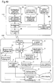
Figure 59 shows a method of transmitting video data
of the digital TV broadcasting in the prior art digital
broadcasting system. First, a construction of the
prior art digital broadcasting system will be described
with reference to figure 59. In the figure, reference
numeral 100 designates a transmitting end, i.e., a
digital broadcasting transmitting apparatus, and
reference numeral 200 designates a receiving end, i.e.,
a digital broadcasting reproducing apparatus for a
network in the digital broadcasting system. The
digital broadcasting transmitting apparatus 100
includes an interlace video data storage unit 20, a
video data packet creating unit 21, a service
information storage unit 26, a service information
packet creating unit 27, a multiplexing unit 28, and a
transmitting unit 29. Specifically, the interlace
video data storage unit 20 is used for storing
interlace video data. The video data packet creating
unit 21 is used for creating packets to-be-transmitted
from video data stored in the interlace video data
storage unit 20. The service information storage unit
26 is used for storing information about transmitted
data to be added to multiplexed data to-be-transmitted.
The service information packet creating unit 27 is used
for creating packets to-be-transmitted from the
information stored in the service information storage
unit 26. The multiplexing unit 28 is used for
multiplexing the interlace video data packets and the
service information packets, to create multiplexed data
to-be-transmitted. The transmitting unit 29 is used
for transmitting the multiplexed data from the
multiplexing unit 28. Although audio data is packeted
and included in the multiplexed data in the
transmitting apparatus 100, this will not be shown for
simplicity.
The digital broadcasting reproducing apparatus 200
includes a receiving unit 1, a separating unit 2, an
interlace video decoding unit 4, a program selecting
unit 6a, and a video display 8. Specifically, the
receiving unit 1 is used for receiving the multiplexed
data. The separating unit 2 is used for separating
video data or required information from the multiplexed
data. The program selecting unit 6a is used for
accepting program selection of the viewer, and
informing the receiving unit 1 and the separating unit
2 of the selected program. As the program selecting
unit 6a, a remote controller, a TV channel button, a
mouse for personal computers, and so forth, which are
all widely available, are used for input. The
interlace video decoding unit 4 is used for decoding
the interlace video data from the separating unit 2 and
outputting a decoded video signal. The video display 8
is implemented by monitor and display, and used for
displaying the decoded video signal as video. Although
in a normal digital broadcasting reproducing apparatus,
various components other than these, for example, a
decoding unit for decoding audio data, are required,
they are dispensed with herein.
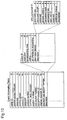
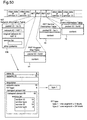
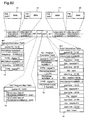
Figure 60 shows a structure of the multiplexed data
of the digital TV broadcasting according to the prior
art digital broadcasting transmitting method.
Referring to figure 60, video data of PROGRAM NUMBER 1
and 3, service information NIT, PMT (Program Map Table),
SDT, and EIT are multiplexed on a packet basis on a
frequency of 12.568GHz. In case of digital data
transmission according to MPEG, plural PROGRAMS
(corresponding to channels in normal analog
broadcasting) are multiplexed and transmitted. These
service information is used to select a desired program
of a desired PROGRAM from the multiplexed data, and
therefore these service information is also multiplexed
and transmitted.
Data structures of these packets and the
multiplexing are defined in MPEG, and will be described
below.
A packet 11 is a packet containing video data of
PROGRAM NUMBER 1 (channel 1). Assuming that a packet
ID in front of the packet 11 is 0x91, the packet 11 is
recognized as a packet of video data of the PROGRAM
NUMBER 1 by the receiving end. A packet 12 is a
packet containing video data of PROGRAM NUMBER 3
(channel 3). Assuming that a packet ID in front of the
packet 12 is 0x93, the packet 12 is recognized as a
packet of video data of the PROGRAM NUMBER 3 by the
receiving end.
Packets 13∼16 are service information packets. The
packet 13 is an NIT packet, and defines a frequency on
which video data of PROGRAM NUMBERs 1 and 3 is
transmitted. In this illustrated example, the video
data of PROGRAM NUMBERs 1 and 3 is multiplexed and
transmitted on 12.568GHz. A packet 14 is a PMT
(Program Map table) packet, and illustrates that the
video data of PROGRAM NUMBER 1 is contained in the
packet of packet ID 0x91, and the video data of PROGRAM
NUMBER 3 is contained in the packet of packet ID 0x93.
A packet 15 is an EIT packet, and in general, there are
two types of EIT packets, namely, a PF-EIT packet which
contains information about present and following events,
and an SC-EIT packet which contains information
(schedule) about a relatively long-term (a week) event.
The EIT packet 15 herein is SC-EIT packet indicative of
schedule, and illustrates that in PROGRAM NUMBER 1,
"baseball 1" from 19:00 to 20:00, "quiz" from 20:00 to
21:00, and "western movie" after 21:00, are supposed to
be broadcast, and in PROGRAM NUMBER 3, "baseball 1"
from 19:00 to 20:00, "soccer" from 20:00 to 21:00,
"baseball 2" from 21:00 to 22:00, and "news" after
22:00 are supposed to be broadcast. A packet 16 is an
SDT packet, and contains information for each service
(PROGRAM) i.e., information indicative of PROGRAM
NUMBER, type, and name for identification.
Next, operation of the prior art digital
broadcasting transmitting apparatus 100, and the prior
art digital broadcasting reproducing apparatus 200 will
be described.
Referring to figure 59 again, in the digital
broadcasting transmitting apparatus 100, the video data
packet creating unit 21 creates packets comprising a
prescribed amount of data from the interlace video data
stored in the interlace video data storage unit 20 as
packets of video data of PROGRAM NUMBER 1 and PROGRAM
NUMBER 3.
The service information packet creating unit 27
obtains required information from the service
information storage unit 26, and creates NIT, PMT, EIT,
and SDT as packets of prescribed bit lengths,
respectively. The multiplexing means 28 multiplexes
these packets as shown in figure 60, and the
transmitting unit 29 transmits the resulting
multiplexed packets.
The multiplexed data is transmitted to the
reproducing apparatus of the viewer in micro wave, or
by cable, to be utilized by the viewer. In the digital
broadcasting reproducing apparatus 200, video data is
reproduced as stated below.
The program selecting unit 6a accepts selection by
the viewer, and informs the receiving unit 1 of the
selected program. The viewer can directly give
instructions on PROGRAM NUMBER by switching or
inputting number, such as by specifying channels in
normal TV.
Also, the viewer can select PROGRAM by visual interface
using a program table mentioned later.
The receiving unit 1 uses the transmitted NIT to
receive signals of a frequency on which the video data
of the specified program, i.e., PROGRAM NUMBER is
transmitted, in compliance with selection by the viewer.
The receiving unit 1 can obtain information contained
in an NIT from an arbitrary transmitted signal, since
any frequency signal includes a multiplexed NIT of the
same contents.
As described above, in the prior art digital
broadcasting system using the reproducing apparatus
designed for the corresponding network, a network ID is
obtained from an NIT of a received transport stream,
and only when the network ID indicates the
corresponding network, the reproducing apparatus
performs processing to the transport stream.
In the receiving apparatus for use in A type system,
a network ID and an original network ID of the
corresponding transport stream are respectively
extracted, to make comparison for them, and only when a
match is found between them, receiving processing is
performed. On the other hand, in the receiving
apparatus for use in B type system, the original
network ID is not extracted, or comparison is not made
for them, and receiving processing is performed
irrespective of contents of information of the original
network ID.
Upon start of receiving processing, the receiving
unit 1 checks contents of the NIT, to detect a value of
frequency on which a signal of video data of a
specified PROGRAM NUMBER is transmitted, and then
selects frequency.
The separating
unit 2 performs separation of the
information received by the receiving
unit 1 to obtain
appropriate video data, on the basis of specification
of the
program selecting unit 6a. More specifically,
where reproduction of video data of
PROGRAM NUMBER 1 is
specified by the
program selecting unit 6a, contents of
the PMT are checked to confirm that the packet ID of
video data of
PROGRAM NUMBER 1 is
0x91
" and then a
0x91
" packet is extracted and sent to the interlace
video decoding unit 4. Likewise, where reproduction of
video data of
PROGRAM NUMBER 3 is specified by the
program selecting unit 6a, contents of the PMT are
checked to confirm that the packet ID of video data of
PROGRAM NUMBER 3 is
0x93
" and then a
0x93
" packet is
extracted and sent to the interlace
video decoding unit
4.
Upon receipt of the video data from the separating
unit 2, the interlace video decoding unit 4 decodes the
video data by the interlace method, and outputs a
decoded video signal to the video display 8, which
displays an image of the decoded video signal on a
screen.
Audio data is also processed in the same manner,
although this is not shown.
Further, in the digital communication system, it
is possible that service information added to video and
audio data is used to offer information to viewers, or
to improve an operation interface. Hereinafter, an
example of utilizing the service information will be
described.
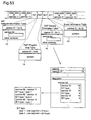
Figure 61 shows a prior art digital broadcasting
reproducing apparatus having a program table display
function and figure 62 illustrates a program table
displayed on a screen of the apparatus. In the digital
broadcasting reproducing apparatus, the schedule
information of the EIT in figure 60 is separated by the
separating unit 2 and processed by a program table
creating table 30, and the resulting table is displayed
on a screen shown in figure 62 in a visualized form.
The viewer selects a desired program using a cursor, a
remote controller, or the like as he/she likes, by
referring to the program table, and the selection is
obtained by the program selecting unit 6a.
While only the interlace video data is processed in
the aforesaid examples, non-interlace video data can be
processed in the same manner, provided that the
transmitting apparatus creates and transmits
multiplexed data of non-interlace video data, and the
reproducing apparatus is provided with a non-interlace
video decoding unit in place of the interlace video
decoding unit.
With respect to the relationship between the
multiplexed data in figure 60 and the digital
broadcasting system in figures 57(a) and 57(b), the
multiplexed data in figure 60 includes no audio data,
and is the transport stream in figure 57(a), and is
broadcast over one of the networks in the digital
broadcasting system in figure 57(b).
As thus far described, according to the prior art
digital broadcasting system, in the transmitting
apparatus, the transmitting method, and the reproducing
apparatus, predetermined video data scanning method or
service information system is constructed for each
network.
Accordingly, one problem associated with the prior
art digital broadcasting system is that system
extension is not facilitated by the fact that the
transmitting apparatus, the transmitting method, and
the reproducing apparatus are configured to one
scanning method .
As mentioned previously, the interlace method is
generally employed in the status quo. In the future,
the non-interlace method may be commonly used, and it
is therefore possible that both interlace video and
non-interlace video are utilized in the same digital
broadcasting system. Accordingly, there is an
increasing demand for a video reproducing apparatus
which reproduces video according to these two methods.
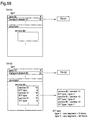
Figures 63(a) to 63(c) show problems with a case
where extension is to be performed using the prior art
transmitting apparatus, the transmitting method, and
the reproducing apparatus.
As shown in figure 63(a), the prior art digital
broadcasting reproducing apparatus is intended for a
network 1 using the interlace method. Therefore,
system extension is facilitated by adding a transport
stream including interlace video data or a network
using the interlace video data thereto.
However, in a case where a transport stream TS101
including non-interlace video data is added as shown in
figure 63(b), or a network 2 using the non-interlace
video data is added as shown in figure 63(c), to extend
the system, the following problems may occur. Although
in the reproducing apparatus intended for an extended
network or a new network, existing transport streams
and added transport streams can be reproduced
correctly, receiving troubles occur caused by using
different scanning methods when a conventional
reproducing apparatus receives the added transport
streams as shown in figures 63(b) and 63(c). The
prior art reproducing apparatuses in figure 59 and 61
respectively perform decoding by the interlace method,
and therefore cannot perform proper decoding to
multiplexed non-interlace video data, and output
appropriate video signals.
In addition, even if these two data coexists, no
problems may occur so long as viewers select and
reproduce only the interlace video data. However,
since the program table does not list contents for
distinguishing a non-interlace program from an
interlace program as shown in figure 62, there is a
possibility that viewers select a program of a scanning
method different from that of a video decoding unit of
the reproducing apparatus by mistake. In the prior art
reproducing apparatus provided with the interlace video
decoding unit, if the viewer selects a non-interlace
program, video data cannot be reproduced correctly,
causing "flicker" video to be output.
Likewise, in a case where the existing digital
broadcasting system is constructed as being a system
that uses only the non-interlace video data, similar
problems may occur when the interlace video data is
used.
In summary, one problem with the prior art system
is as follows.
Another problem associated with the prior art
digital broadcasting system is that service information
transmitting method is predetermined on a fixed basis
for each network, to which the transmitting apparatus
and the receiving apparatus configure themselves, which
makes it difficult to use service information of a
different method.
For instance, the schedule information contained in
the EIT is handled per segment of a predetermined time.
As the predetermined time, 3 hours is assumed to be one
segment, and segment numbers are allocated to the
corresponding segments in a prescribed manner.
Specifically, the segment numbers are allocated every
three hours starting with
0
", or every day starting
with
0
". The manner is determined for each network on
a fixed basis. For example, in the
network 1 in figure
57(b), on assumption that 3 hours is one segment, the
segment numbers are sequentially allocated to
respective segments.
As a consequence, when a service (PROGRAM) often
includes long events, and therefore use of a 24 hour
segment can create data to-be-transmitted with higher
efficiency rather than use of a 3 hour segment, a
method different from a method for use by a network to
which the service belongs is not employed.
In brief, in the prior art digital broadcasting
system, data cannot be used flexibly, which makes it
difficult to realize system extension.
SUMMARY OF THE INVENTION
It is an object of the present invention to provide
a digital broadcasting transmitting method in which a
digital broadcasting system constructed for one of
interlace video data and non-interlace video data is
extended by addition, a video data scanning method is
specified for each network or for each service, and
these video data is reproduced correctly in a receiving
end, whereby degree of freedom in construction of a
program to-be-transmitted is improved.
It is another object of the present invention to
provide a digital broadcasting transmitting apparatus
which implements the digital broadcasting transmitting
method.
It is still another object of the present invention
to provide a digital broadcasting reproducing apparatus
which receives transmitted data including interlace
video data and non-interlace video data, and reproduces
these video data correctly, to be displayed, in the
extended digital broadcasting system.
It is a further object of the present invention to
provide a digital broadcasting reproducing apparatus
which identifies a scanning method of a selected
program and prevents wrong selection when any of plural
programs including interlace video data and non-interlace
video data is selected and reproduced, in the
extended digital broadcasting system.
It is a still further object of the present
invention to provide a digital broadcasting
transmitting method, a digital broadcasting
transmitting apparatus, and a digital broadcasting
reproducing apparatus in which service information
transmitted by different methods is available.
Other objects and advantages of the invention will
become apparent from the detailed description that
follows. The detailed description and specific
embodiments described are provided only for
illustration since various additions and modifications
within the spirit and scope of the invention will be
apparent to those skill in the prior art from the
detailed description.
According to a first aspect of the present
invention, a digital broadcasting transmitting method
wherein a transport stream is created and transmitted
in a digital broadcasting system in which the transport
stream in which plural packets comprising video data
packets of digitized video and service information
packets of information about broadcasting using the
video have been multiplexed, is transmitted over a
network, comprises the step of creating and
transmitting the transport stream in which the service
information includes scanning method information as
information about a scanning method of digitizing the
video.
As a result, in a receiving end, processing is
correctly performed using the scanning method
information.
According to a second aspect of the present
invention, in the digital broadcasting transmitting
method of the first aspect, to an existing digital
broadcasting system using video digitized by a
specified scanning method, a transport stream including
a packet of video digitized by another scanning method
is added, and the scanning method information included
in the service information includes: information for
distinguishing a transport stream which belongs to the
existing digital broadcasting system from the transport
stream to be added; and information for specifying a
scanning method of the video of the packet multiplexed
into the transport stream to be added.
According to a third aspect of the present
invention, in the digital broadcasting transmitting
method of the first aspect, the scanning method
information includes network scanning method
information indicative of a scanning method of video
data transmitted over a network as information for each
network.
According to a fourth aspect of the present
invention, in the digital broadcasting transmitting
method of the first aspect, the scanning method
information includes transport stream scanning method
information indicative of a scanning method of video
data included in the transport stream as information
for each transport stream.
According to a fifth aspect of the present
invention, in the digital broadcasting transmitting
method of the first aspect, the scanning method
information is contained in an network information
table indicative of network information, of the service
information.
According to a sixth aspect of the present
invention, in the digital broadcasting transmitting
method of the fifth aspect, the scanning method
information is included in an original network
identifier contained in the network information table,
indicative of an original network over which a
transport stream must be transmitted.
According to a seventh aspect of the present
invention, in the digital broadcasting transmitting
method of the fifth aspect, the scanning method
information is included in a network identifier
contained in the network information table, indicative
of a network over which a transport stream is
transmitted.
According to an eighth aspect of the present
invention, in the digital broadcasting transmitting
method of the seventh aspect, information indicative of
a network over which a transport stream is transmitted
is included in a network name given to the network,
contained in the network information table.
According to a ninth aspect of the present
invention, in the digital broadcasting transmitting
method of the first aspect, in the digital broadcasting
system, a service comprises one or more programs, and
the scanning method information includes service
scanning method information indicative of the scanning
method of the video data as information for each
service.
According to a tenth aspect of the present
invention, in the digital broadcasting transmitting
method of the ninth aspect, the service scanning method
information is contained in a network information table
indicative of network information.
According to an eleventh aspect of the present
invention, in the digital broadcasting transmitting
method of the tenth aspect, the service scanning method
information is included in a service type in a service
list descriptor contained in the network information
table, indicative of a service to be offered by a
network.
According to a twelfth aspect of the present
invention, in the digital broadcasting transmitting
method of the tenth aspect, the service scanning method
information is included in a service identifier in a
service list descriptor contained in the network
information table, indicative of a service to be
offered by a network.
According to a thirteenth aspect of the present
invention, in the digital broadcasting transmitting
method of the twelfth aspect, information for
specifying a service is included in a service name in
the service list descriptor.
According to a fourteenth aspect of the present
invention, in the digital broadcasting transmitting
method of the ninth aspect, the service scanning method
information is contained in a service description table
indicative of service information of a transport stream.
According to a fifteenth aspect of the present
invention, in the digital broadcasting transmitting
method of the fourteenth aspect, the service scanning
method information is included in a service type in a
service list descriptor contained in the service
description table, indicative of a service to be
offered by a transport stream.
According to a sixteenth aspect of the present
invention, in the digital broadcasting transmitting
method of the fourteenth aspect, the service scanning
method information is included in a service identifier
in a service list descriptor contained in the service
description table, indicative of a service to be
offered by a transport stream.
According to a seventeenth aspect of the present
invention, in the digital broadcasting transmitting
method of the sixteenth aspect, information for
specifying a service is included in a service name in
the service list descriptor.
According to an eighteenth aspect of the present
invention, in the digital broadcasting transmitting
method of the first aspect, in the digital broadcasting
system, plural programs are transmitted, and
the scanning method information includes program
scanning method information indicative of the scanning
method of the video data as information for each
program.
According to a nineteenth aspect of the present
invention, in the digital broadcasting transmitting
method of the eighteenth aspect, the program scanning
method information is contained in an event information
table indicative of program information.
According to a twentieth aspect of the present
invention, in the digital broadcasting transmitting
method of claim of the nineteenth aspect, the program
scanning method information is included in an event
list descriptor contained in the event information
table.
According to a 21st aspect of the present invention,
a digital broadcasting transmitting method wherein a
transport stream is created and transmitted in a
digital broadcasting system in which the transport
stream in which plural packets comprising video data
packets of digitized video and service information
packets of information about broadcasting using the
video have been multiplexed, is transmitted over a
network, comprises:
According to a 22nd aspect of the present invention,
in the digital broadcasting transmitting method of the
21st aspect, the transmitting method information of the
event information table is contained in a network
information table indicative of network information.
According to a 23rd aspect of the present invention,
in the digital broadcasting transmitting method of the
22nd aspect, the transmitting method information of the
event information table is included in an event
information table type identifier in a descriptor
contained in the network information table, and
specifies the transmitting method of the event
information table for each network.
According to a 24th aspect of the present invention,
in the digital broadcasting transmitting method of the
22nd aspect, the transmitting method information of the
event information table is included in an event
information table type identifier in a transport stream
descriptor contained in the network information table,
indicative of a transport stream to be offered by a
network, and specifies the transmitting method of the
event information table for each transport stream.
According to a 25th aspect of the present invention,
in the digital broadcasting transmitting method of the
22nd aspect, the transmitting method information of the
event information table is included in an event
information table type identifier in a service list
descriptor contained in the network information table,
indicative of a service to be offered by a network, and
specifies the transmitting method of the event
information table for each service.
According to a 26th aspect of the present invention,
in the digital broadcasting transmitting method of the
21st aspect, the transmitting method information of the
event information table is contained in a service
description table indicative of service information of
a transport stream.
According to a 27th aspect of the present invention,
in the digital broadcasting transmitting method of the
26th aspect, the transmitting method information of the
event information table is included in an event
information table type identifier in a service list
descriptor contained in the service description table,
indicative of a service included in a transport stream,
and specifies the transmitting method of the event
information table for each service.
According to a 28th aspect of the present invention,
a digital broadcasting transmitting apparatus which
creates and transmits a transport stream in a digital
broadcasting system in which the transport stream in
which plural packets comprising video data packets of
digitized video and service information packets of
information about broadcasting using the video have
been multiplexed, is transmitted over a network,
comprises:
As a result, in a receiving end, processing is
correctly performed using the scanning method
information.
According to a 29th aspect of the present invention,
in the digital broadcasting transmitting apparatus of
the 28th aspect, to an existing digital broadcasting
system using video digitized by a specified scanning
method, a transport stream including a packet of video
digitized by another scanning method is added, and the
service information packet creating unit creates the
service information packet in which the scanning method
information includes: information for distinguishing a
transport stream which belongs to the existing digital
broadcasting system from the transport stream to be
added; and information for specifying a scanning method
of video of a packet multiplexed into the transport
stream to be added.
According to a 30th aspect of the present invention,
in the digital broadcasting transmitting apparatus of
the 28th aspect, the service information packet
creating unit gives network scanning method
information indicative of a scanning method of video
data transmitted over a network as information for each
network, as the scanning method information.
According to a 31st aspect of the present invention,
in the digital broadcasting transmitting apparatus of
28th aspect, the service information packet creating
unit gives transport stream scanning method information
indicative of a scanning method of video data included
in the transport stream as information for each
transport stream, as the scanning method information.
According to a 32nd aspect of the present invention,
in the digital broadcasting transmitting apparatus of
the 28th aspect, the service information packet
creating unit gives the scanning method information to
a network information table packet indicative of
network information, of the service information.
According to a 33rd aspect of the present invention,
in the digital broadcasting transmitting apparatus of
the 32nd aspect, the service information packet
creating unit gives the scanning method information to
an original network identifier contained in the network
information table packet, indicative of an original
network over which a transport stream must be
transmitted.
According to a 34th aspect of the present invention,
in the digital broadcasting transmitting apparatus of
the 32nd aspect, the service information packet
creating unit gives the scanning method information to
a network identifier contained in the network
information table packet, indicative of a network over
which a transport stream is transmitted.
According to a 35thaspect of the present invention,
in the digital broadcasting transmitting apparatus of
the 34th aspect, the service information packet
creating unit gives information for specifying a
network to a network name contained in the network
information table packet, indicative of a name given to
the network.
According to a 36th aspect of the present invention,
in the digital broadcasting transmitting apparatus of
the 28th aspect, in the digital broadcasting system, a
service comprises one or more programs, and the service
information packet creating unit gives the scanning
method information including service scanning method
information indicative of the video data scanning
method as information for each service.
According to a 37th aspect of the present invention,
in the digital broadcasting transmitting apparatus of
the 36th aspect, the service information packet
creating unit gives the service scanning method
information to a network information table packet
indicative of network information.
According to a 38th aspect of the present invention,
in the digital broadcasting transmitting apparatus of
the 37th aspect, the service information packet
creating unit gives the service scanning method
information to a service type in a service list
descriptor contained in the network information table
packet, indicative of a service to be offered by a
network.
According to a 39th aspect of the present invention,
in the digital broadcasting transmitting apparatus of
the 37th aspect, the service information packet
creating unit gives the service scanning method
information to a service identifier in a service list
descriptor contained in the network information table
packet, indicative of a service to be offered by a
network.
According to a 40th aspect of the present invention,
in the digital broadcasting transmitting apparatus of
the 39th aspect, the service information packet
creating unit gives information for specifying a
service to a service name in the service list
descriptor.
According to a 41st aspect of the present invention,
in the digital broadcasting transmitting apparatus of
the 36th aspect, the service information packet
creating unit gives the service scanning method
information to a service description table packet
indicative of service information of a transport stream.
According to a 42nd aspect of the present invention,
in the digital broadcasting transmitting apparatus of
the 41st aspect, the service information packet
creating unit gives the service scanning method
information to a service type in a service list
descriptor contained in the service description table
packet, indicative of a service to be offered by a
transport stream.
According to a 43rd aspect of the present invention,
in the digital broadcasting transmitting apparatus of
the 41st aspect, the service information packet
creating unit gives the service scanning method
information to a service identifier in a service list
descriptor contained in the service description table
packet, indicative of a service to be offered by a
transport stream.
According to a 44th aspect of the present invention,
in the digital broadcasting transmitting apparatus of
the 43rd aspect, the service information packet
creating unit gives information for specifying a
service to a service name in the service list
descriptor.
According to a 45th aspect of the present aspect,
in the digital broadcasting transmitting apparatus of
the 28th aspect, in the digital broadcasting system,
plural programs are transmitted, and the service
information packet creating unit creates the scanning
method information including program scanning method
information as information indicative of a scanning
method of the video data for each program.
According to a 46th aspect of the present invention,
in the digital broadcasting transmitting apparatus of
the 45th aspect, the service information packet
creating unit gives the program scanning method
information to an event information table packet
indicative of program information.
According to a 47th aspect of the present invention,
in the digital broadcasting transmitting apparatus of
the 46th aspect, the service information packet
creating unit gives the program scanning method
information to an event list descriptor contained in
the event information table packet.
According to a 48th aspect of the present invention,
a digital broadcasting transmitting apparatus which
creates and transmits a transport stream in a digital
broadcasting system in which the transport stream in
which plural packets comprising video data packets of
digitized video and service information packets of
information about broadcasting using the video have
been multiplexed, is transmitted over a network,
comprises:
According to a 49th aspect of the present invention,
in the digital broadcasting transmitting apparatus of
the 48th aspect, the service information packet
creating unit gives the transmitting method information
of the event information table to a network information
table packet indicative of network information.
According to a 50th aspect of the present invention,
in the digital broadcasting transmitting apparatus of
the 49th aspect, the service information packet
creating unit gives the transmitting method information
of the event information table for specifying a
transmitting method for each network to an event
information table type identifier in a descriptor
contained in the network information table packet.
According to a 51st aspect of the present invention,
in the digital broadcasting transmitting apparatus of
the 49th aspect, the service information packet
creating unit gives the transmitting method information
of the event information table for specifying a
transmitting method for each transport stream to an
event information table type identifier in a transport
stream list descriptor contained in the network
information table packet, indicative of a transport
stream to be offered by a network.
According to a 52nd aspect of the present invention,
in the digital broadcasting transmitting apparatus of
the 49th aspect, the service information packet
creating unit gives the transmitting method information
of the event information table for specifying the
transmitting method of the event information table for
each service, to an event information table type
identifier in a service list descriptor contained in
the network information table packet, indicative of a
service to be offered by a network.
According to a 53rd aspect of the present invention,
in the digital broadcasting transmitting apparatus of
the 48th aspect, the service information packet
creating unit gives the transmitting method information
of the event information table to a service description
table packet indicative of service information of a
transport stream.
According to a 54th aspect of the present invention,
in the digital broadcasting transmitting apparatus of
the 53rd aspect, the service information packet
creating unit gives the transmitting method information
of the event information table for specifying the
transmitting method of the event information table for
each service to an event information table type
identifier in a service list descriptor contained in
the service description table packet, indicative of a
service given to a transport stream.
According to a 55th aspect of the present invention,
a digital broadcasting reproducing apparatus which
receives a transport stream and reproduce video from
video data using service information in a digital
broadcasting system in which the transport stream in
which plural packets comprising video data packets of
digitized video and service information packets of
information about broadcasting using the video have
been multiplexed, is transmitted over a network,
comprises:
As a result, the apparatus obtains scanning method
information included in the service information, and
perform reproduction according to the corresponding
scanning method.
According to a 56th aspect of the present invention,
in the digital broadcasting reproducing apparatus of
the 55th aspect further comprises an identification
information decision unit for instructing said
separating unit to separate and extract information
required for program creation from the received
multiplexed data on the basis of the information stored
in said identification information storage unit; a
program table storage unit for storing information
required for program creation which has been separated
and extracted by said separating unit in accordance
with the instruction from said identification
information decision unit; and a program table creating
unit for creating a program table in the digital
broadcasting system on the basis of the information
stored in said program table storage unit.
As a result, the program table is displayed
appropriately using program table information included
in the service information.
According to a 57th aspect of the present
invention, in the digital broadcasting reproducing
apparatus of the 56th aspect, the identification
information storage unit stores information for
specifying a scanning method of the video data of the
service information which is multiplexed into the
transport stream and transmitted, and the
identification information decision unit instructs
said separating unit to separate and extract the
information required for program creation and the
information for specifying the scanning method from the
received multiplexed data on the basis of the
information stored in said identification information
storage unit; and the program table creating unit
creates the program table including the scanning method
information.
According to a 58th aspect of the present invention,
in the digital broadcasting reproducing apparatus of
the 56th aspect, the identification information storage
unit stores transmitting method information of an event
information table which specifies the transmitting
method of the event information table of the service
information which is multiplexed into the transport
stream and transmitted, and the identification
information decision unit instructs said separating
unit to separate and extract information required for
program creation from the received multiplexed data on
the basis of the transmitting method information of the
event information table stored in said identification
information storage unit.
BRIEF DESCRIPTION OF THE DRAWINGS
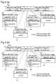
Figure 1 is a block diagram illustrating a digital
broadcasting transmitting apparatus and a digital
broadcasting reproducing apparatus according to a first
embodiment of the invention.
Figures 2(a)-2(c) are diagrams for explaining the
relationship between a digital broadcasting system
according to the first embodiment and the existing
digital broadcasting system.
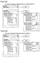
Figures 3(a) and 3(b) are diagrams each
illustrating an NIT (network information table)
transmitted in the digital broadcasting transmitting
method according to the first embodiment.
Figures 4(a) and 4(b) are diagrams each
illustrating the structure of multiplexed data
transmitted in the digital broadcasting transmitting
method according to the first embodiment.
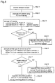
Figure 5 is a flowchart for explaining the
operation of the digital broadcasting reproducing
apparatus according to the first embodiment.
Figures 6(a) and 6(b) are diagrams each
illustrating an NIT transmitted in another example of
the digital broadcasting transmitting method according,
to the first embodiment.
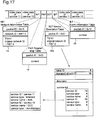
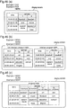
Figure 7(a) is a diagram illustrating an NIT
transmitted in a digital broadcasting transmitting
method according to a first example of a second
embodiment of the invention, and figure 7(b) is a
diagram illustrating code allocation employed in the
method.
Figure 8 is a flowchart for explaining the
operation of a digital broadcasting reproducing
apparatus according to the first example of the second
embodiment.
Figure 9 is a diagram showing an NIT and an EIT
(event information table) transmitted in a digital
broadcasting transmitting method according to a second
example of the second embodiment.
Figure 10 is a diagram for explaining an example of
scanning method specification using the EIT employed in
the digital broadcasting transmitting method according
to the second example of the second embodiment.
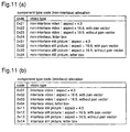
Figures 11(a) and 11(b) are diagrams illustrating
examples of scanning method ID code allocation in the
digital broadcasting transmitting method according to
the second example of the second embodiment.
Figure 12 is a flowchart for explaining the
operation of a digital broadcasting reproducing
apparatus according to the second example of the second
embodiment.
Figures 13(a)-13(c) are diagrams for explaining the
relationship between a digital broadcasting system
according to a third embodiment of the invention and
the existing digital broadcasting system.
Figures 14(a) and 14(b) are diagrams each
illustrating an NIT transmitted in a digital
broadcasting transmitting method according to the third
embodiment.
Figure 15 is a flowchart for explaining the
operation of a digital broadcasting reproducing
apparatus according to the third embodiment.
Figure 16 is a diagram illustrating the structure
of multiplexed data transmitted in the digital
broadcasting transmitting method according to the third
embodiment.
Figure 17 is a diagram illustrating the structure
of multiplexed data transmitted in a digital
broadcasting transmitting method according to another
example of the third embodiment.
Figures 18(a) and 18(b) are diagrams each
illustrating an NIT transmitted in a digital
broadcasting transmitting method according to a fourth
embodiment of the invention.
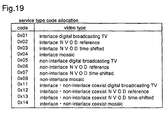
Figure 19 is a diagram illustrating an example of
scanning method ID code allocation in the digital
broadcasting transmitting method according to the
fourth embodiment.
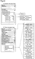
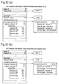
Figure 20 is a diagram illustrating an NIT and an
EIT transmitted in the digital broadcasting
transmitting method according to the fourth embodiment.
Figure 21 is a flowchart for explaining the
operation of a digital broadcasting reproducing
apparatus according to the fourth embodiment.
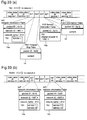
Figure 22 is a diagram illustrating an NIT and an
EIT transmitted in a digital broadcasting transmitting
method according to another example of the fourth
embodiment.
Figure 23 is a flowchart for explaining the
operation of a digital broadcasting reproducing
apparatus according to the example of the fourth
embodiment.
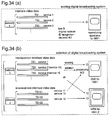
Figures 24(a) and 24(b) are diagrams for explaining
the relationship between a digital broadcasting system
according to a fifth embodiment of the invention and
the existing digital broadcasting system.
Figures 25(a) and 25(b) are diagrams each
illustrating an NIT transmitted in a digital
broadcasting transmitting method according to the fifth
embodiment.
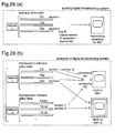
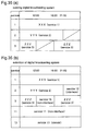
Figures 26(a) and 26(b) are diagrams each
illustrating the structure of multiplexed data
transmitted in the digital broadcasting transmitting
method according to the fifth embodiment.
Figure 27 is a flowchart for explaining the
operation of a digital broadcasting reproducing
apparatus according to the fifth embodiment.
Figures 28(a) and 28(b) are diagrams for explaining
the relationship between a digital broadcasting system
according to a sixth embodiment of the invention and
the existing digital broadcasting system.
Figures 29(a) and 29(b) are diagrams each
illustrating an NIT transmitted in a digital
broadcasting transmitting method according to the sixth
embodiment.
Figures 30(a) and 30(b) are diagrams each
illustrating the structure of multiplexed data
transmitted in the digital broadcasting transmitting
method according to the sixth embodiment.
Figure 31 is a flowchart for explaining the
operation of a digital broadcasting reproducing
apparatus according to the sixth embodiment.
Figures 32(a) and 32(b) are diagrams each
illustrating an NIT transmitted in a digital
broadcasting transmitting method according to a seventh
embodiment of the invention.
Figures 33(a) and 33(b) are diagrams each
illustrating the structure of multiplexed data
transmitted in the digital broadcasting transmitting
method according to the seventh embodiment.
Figures 34(a) and 34(b) are diagrams for explaining
the relationship between a digital broadcasting system
according to an eighth embodiment of the invention and
the existing digital broadcasting system.
Figures 35(a) and 35(b) are diagrams for explaining
extension of program construction by a digital
broadcasting transmitting method according to the
eighth embodiment.
Figures 36(a) and 36(b) are diagrams each
illustrating an NIT transmitted in the digital
broadcasting transmitting method according to the
eighth embodiment.
Figure 37 is a flowchart for explaining the
operation of a digital broadcasting reproducing
apparatus according to the eighth embodiment.
Figures 38(a) and 38(b) are diagrams each
illustrating an NIT transmitted in a digital
broadcasting transmitting method according to a ninth
embodiment of the invention.
Figures 39(a)-39(c) re diagrams each illustrating
the structure of multiplexed data transmitted in the
digital broadcasting transmitting method according to
the ninth embodiment.
Figures 40(a) and 40(b) are diagrams illustrating
the structure of multiplexed data transmitted in the
digital broadcasting transmitting method according to
the ninth embodiment.
Figure 41 is a diagram for explaining functions of
reproduction apparatuses in an extended digital
broadcasting system.
Figure 42 is a block diagram illustrating a digital
broadcasting reproducing apparatus having program table
display function according to a tenth embodiment of the
invention.
Figure 43 is a block diagram illustrating a digital
broadcasting reproducing apparatus having program table
display function, which can reproduce both of interlace
video data and non-interlace video data, according to
the tenth embodiment.
Figure 44 is a block diagram illustrating a digital
broadcasting reproducing apparatus having a function of
program table display, which can reproduce interlace
video data, according to the tenth embodiment.
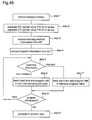
Figure 45 is a flowchart for explaining the
operation of a digital broadcasting reproducing
apparatus according to the tenth embodiment.
Figures 46(a)-46(c) are diagrams illustrating
examples of program table display screens of the
digital broadcasting reproducing apparatus according to
the tenth embodiment.
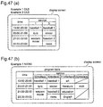
Figures 47(a) and 47(b) are diagrams illustrating
examples of program table display screens of the
digital broadcasting reproducing apparatus according to
the tenth embodiment.
Figures 48(a) and 48(b) are diagrams illustrating
examples of program table display screens of the
digital broadcasting reproducing apparatus according to
the tenth embodiment.
Figure 49 is a diagram illustrating a digital
broadcasting transmitting apparatus and a digital
broadcasting reproducing apparatus according to an
eleventh embodiment of the invention.
Figure 50 is a diagram illustrating the structure
of multiplexed data transmitted in a digital
broadcasting transmitting method according to a first
example of the eleventh embodiment.
Figure 51 is a diagram illustrating the structure
of multiplexed data transmitted in a digital
broadcasting transmitting method according to a second
example of the eleventh embodiment.
Figure 52 is a diagram illustrating the structure
of multiplexed data transmitted in a digital
broadcasting transmitting method according to a third
example of the eleventh embodiment.
Figure 53 is a diagram illustrating the structure
of multiplexed data transmitted in a digital
broadcasting transmitting method according to a fourth
example of the eleventh embodiment.
Figure 54 is a diagram illustrating an NIT
transmitted in a digital broadcasting transmitting
method according to a twelfth embodiment of the
invention.
Figure 55 is a diagram illustrating an NIT and an
SDT (service description table) transmitted in the
digital broadcasting transmitting method according to
the twelfth embodiment.
Figure 56 is a diagram illustrating an NIT and an
SDT transmitted in a digital broadcasting transmitting
method according to a thirteenth embodiment of the
invention.
Figure 57(a) is a diagram for explaining
multiplexing of data and generation of a transport
stream in a conventional digital broadcasting, and
figure 57(b) is a diagram for explaining networks and
transport streams.
Figure 58 is a diagram illustrating an NIT, an SDT,
and an EIT included in the above-described multiplexed
data.
Figure 59 is a block diagram illustrating a digital
broadcasting transmitting apparatus and a digital
broadcasting reproducing apparatus according to the
prior art.
Figure 60 is a diagram illustrating the structure
of a transport stream (multiplexed data) transmitted in
a digital broadcasting transmitting method according to
the prior art.
Figure 61 is a block diagram illustrating a digital
broadcasting reproducing apparatus having program table
display function according to the prior art.
Figure 62 is a diagram illustrating a program table
displayed on a display screen in the digital
broadcasting reproducing apparatus according to the
prior art.
Figures 63(a)-63(c) are diagrams for explaining
problems in extending a digital broadcasting system
according to the prior art.
DETAILED DESCRIPTION OF THE PREFERRED EMBODIMENTS
Now, preferred embodiments of the present invention
will be described with reference to figures.
[Embodiment 1]
A digital broadcasting transmitting method
according to a first embodiment of the present
invention is characterized in that an original network
ID has network scanning method information indicative
of a scanning method of video data transmitted over a
network as information for each network.
In this embodiment, a digital broadcasting
transmitting method, a digital broadcasting
transmitting apparatus, and a digital broadcasting
reproducing apparatus are illustrated, in which a
transport stream or a network using data of a different
scanning method is added to an existing system
constructed for video data of a single scanning method,
to extend the system. First, constructions of the
digital broadcasting transmitting apparatus and
reproducing apparatus will be described with reference
to figure 1.
Figure 1 shows a digital broadcasting transmitting
apparatus, and a digital broadcasting reproducing
apparatus of the first embodiment referred to herein by
reference numerals 110 and 210, respectively.
The digital broadcasting transmitting apparatus 110
comprises an interlace video data storage unit 20, an
interlace video data packet creating unit 21, a non-interlace
video data storage unit 22, a non-interlace
video data packet creating unit 23, a service
information storage unit 26, a service information
packet creating unit 27, a multiplexing unit 28, and a
transmitting unit 29. More specifically, the interlace
video data storage unit 20 is used for storing
interlace video data. The interlace video data packet
creating unit 21 is used for creating packets-to-be-transmitted
from the video data stored in the interlace
video data storage unit 20. The non-interlace video
data storage unit 22 is used for storing the non-interlace
video data. The non-interlace video data
packet creating unit 23 is used for creating packets-to-be-transmitted
from the video data stored in the
non-interlace video data storage unit 22. The service
information storage unit 26 is used for storing
information about transmitted data which is added to
multiplexed data to-be-transmitted. The service
information packet creating unit 27 is used for
creating packets to-be-transmitted from the information
stored in the service information storage unit 26. The
multiplexing unit 28 is used for multiplexing the
packets of the interlace video data, the packets of the
non-interlace video data, and the packets of the
service information, to create multiplexed data to-be-transmitted.
The transmitting unit 29 is used for
transmitting the multiplexed data from the multiplexing
unit 28.
Thus, in the digital broadcasting transmitting
apparatus 110 of this embodiment, the non-interlace
video data storage unit 22 and the non-interlace video
data packet creating unit 23 are added to the prior art
transmitting apparatus in figure 59. Also, as in the
case of the prior art example, packeting audio data and
multiplexing packeted audio data will not be described
for simplicity.
The digital broadcasting reproducing apparatus 210
comprises a receiving unit 1, a separating unit 2, a
non-interlace video decoding unit 3, an interlace video
decoding unit 4, an identification information storage
unit 5, a service selecting unit 6, a scanning method
instructing unit 7, and a video display 8. More
specifically, the receiving unit 1 is used for
receiving the transmitted multiplexed data as a
transport stream. The separating unit 2 is used for
separating video data or required information from the
multiplexed data received by the receiving unit 1. The
non-interlace video decoding unit 3 is used for
decoding the non-interlace video data separated by the
separating unit 2 and outputting a decoded video signal.
The interlace video decoding unit 4 is used for
decoding the interlace video data separated by the
separating unit 2 and outputting a decoded video signal.
The identification information storage unit 5 is used
for storing scanning method information of the video
data separated by the separating unit 2. The service
selecting unit 6 is used for accepting program
selection of the viewer and informing the receiving
unit 1 and the separating unit 2 of the program
selected by the viewer, and a remote controller for
program selection, a TV channel button, a mouse for
personal computers, and so forth are used for input, as
in the case of the program selecting unit 6a of the
prior art example. The scanning method instructing
unit 7 is used for giving a instruction on whether the
video data separated by the separating unit 2 will be
decoded by the non-interlace video decoding unit 3 or
the interlace video decoding unit 4, to the unit 3 or
the unit 4, respectively, on the basis of the scanning
method information stored in the identification
information storage unit 5. The video display 8 is
implemented by monitor and display, and used for
displaying the decoded video signal as video.
Thus, in the digital broadcasting reproducing
apparatus 210 of this embodiment, the non-interlace
video decoding unit 3, the identification information
storage unit 5, and the scanning method instructing
unit 7 are added to the prior art reproducing apparatus
in figure 59. Also, as in the case of the prior art
example, a decoding unit for audio data and so forth
will not be described for simplicity.
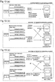
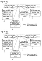
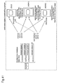
Figure 2(a) shows a digital broadcasting system
using only interlace video data, and figures 2(b) and
2(c) show addition/extension in which non-interlace
video data is used. The system extension can be
performed by transmitting non-interlace video data over
an existing network 1 (see figure 2(b)), and by adding
a network using services including the non-interlace
video data (see figure 2(c)).
The system extension in figure 2(b) will now be
described. Assume that the existing system includes
services 1 and 3 (corresponding to PROGRAM 1 and
PROGRAM 3 in the prior art example), and system
extension is performed by adding services 11 and 13
using only the non-interlace video data.
Also assume that in the existing system, A. In an
receiving end, normal receiving and processing is
carried out only when an original network ID is
recognized, and is identical to a network ID as in the
prior art example. Use of the original network ID
allows video data of a different scanning method to be
used in an extended digital broadcasting system without
adversely affecting the reproducing apparatus only for
the existing system.
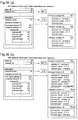
Figure 3(a) and 3(b) show NIT for use in the first
embodiment, and figures 4(a) and 4(b) show transport
streams TS1 and TS101 to-be-transmitted in the extended
digital broadcasting system. As in the prior art
example, the transport stream is multiplexed data
consisting of video data packets and packets of various
types of service information.
In the NIT in figure 3(a), a network ID, and an
original network ID, i.e., information about a
transport stream TS1, are
NET 1
", and therefore the
TS1 is received and processed by the reproducing
apparatus (OLD) for the existing
network 1 in figure 2.
On the other hand, in the NIT in figure 3(b), a
transport stream TS1 is identical to the above-described
transport stream TS1, but to a transport
stream TS101, an original
network ID NET 2
" different
from a
network ID NET 1
" is given, and therefore the
transport stream TS101 is not processed by the OLD if
received. Thus, using the NIT packet in figure 3(b),
the transport stream TS101 cannot be processed by the
reproducing apparatus OLD.
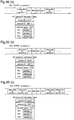
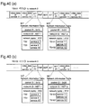
The transport streams TS1 and TS101 in figure 4(a)
and 4(b) are respectively multiplexed data including
the NIT in figure 3(b). Video data packet of each
service is identified by packet ID PID in front of each
packet as in the prior art example. With respect to
the service information packets, the NIT packet
contains information about a network and a transport
stream as mentioned previously, in addition to a
frequency band as in the prior art example. A PMT
packet contains PID of video data of each service as in
the prior art example, which is used along with the PID
of the video data packet to extract video data packets.
An EIT (Event Information Table) packet contains
information about events (programs) to-be-broadcast by
each service as in the prior art example. An SDT
(Service Description Table) packet contains information
for each service. The service information packets are
identified by their respective packet identifiers ID in
front of respective packets as in the prior art example.
It should be noted that the packet identifiers ID in
the figures are only illustrative, and not restricted
thereto so long as they may be given to respective
packets to-be-identified.
Next, operation of the digital broadcasting
transmitting apparatus and the reproducing apparatus of
this embodiment (1) "CREATION AND TRANSMISSION OF
MULTIPLEXED DATA OF DIGITAL BROADCASTING TRANSMITTING
APPARATUS", and (2) "REPRODUCTION OF DIGITAL
BROADCASTING REPRODUCING APPARATUS" will be described.
(1) CREATION AND TRANSMISSION OF MULTIPLEXED DATA OF
DIGITAL BROADCASTING TRANSMITTING APPARATUS
Referring to figure 1 again, the interlace video
data packet creating unit 21 obtains video data
required for program creation of services 1 and 3 from
the interlace video data storage unit 20 to create
interlace video data packets and outputs the interlace
video data packets to the multiplexing unit 28.
The non-interlace video data packet creating unit
23 obtains video data required for program creation of
services 11 and 13 from the non-interlace video data
storage unit 22 to create non-interlace video data
packets and outputs the non-interlace video data
packets to the multiplexing unit 28.
The service information packet creating unit 27
creates the NIT packet in figure 3(b) by setting an
original network ID of TS1 to be "NET 1" and an
original network ID of TS101 to be "NET 2" for each
transport stream in a transport stream list in the NIT
packet. The other service information packets are
created as already described in the prior art example.
The service information packet creating unit 27 outputs
all the service information packets to the multiplexing
unit 28.
The multiplexing unit 28 multiplexes the video data
packets and the service information packets in fixed
sizes, respectively, to create multiplexed data
including video data of services 1 and 3 in figure 4(a),
and multiplexed data including video data of services
11 and 13 in figure 4(b) and outputs these multiplexed
data to the transmitting unit 29, which transmits these
multiplexed data as transport streams TS1 and TS101
over the network 1 (see figure 2).
(2) REPRODUCTION OF DIGITAL BROADCASTING REPRODUCING
APPARATUS
The transport streams TS1 and TS101 are received
and processed (including decoding) by the reproducing
apparatus 201, to reproduce and display video. Here,
the viewer can utilize broadcast video.
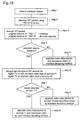
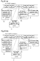
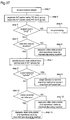
Figure 5 is a flowchart showing processing
procedure of the reproducing apparatus 210 after
receiving the transport streams. Hereinafter,
operation of the reproducing apparatus 210 will be
described following flow in figure 5. Assume that the
reproducing apparatus 210 is for the extended system in
figure 2(b) (expressed as "NEW").
In step 1, the receiving unit 1 receives the
transport stream, i.e., multiplexed data transmitted
over the network 1, and passes the multiplexed data to
the separating unit 2. In step 2, the separating unit
2 separates the NIT packet using packet ID 0x10 as a
key for extraction. In step 3, the NIT packet is
decrypted to obtain scanning method information of
video data from the information of the original network
ID.
In a case where the transport stream TS1 in figure
4(a) is received, since the original network ID of TS1
is "NET 1" from the contents of the NIT in figure 3(b),
it is decided that the video data is interlace video
data. Likewise, in a case where the transport stream
TS101 in figure 4(b) is received, since the original
network ID of TS101 is "NET 2", it is decided that the
video data is non-interlace video data. The scanning
method information obtained in step 3 is stored in the
identification information storage unit 5. As in the
case of the prior art example, the packet ID of video
data included in the PMT packet is also separated by
the separating unit 2 and stored in the identification
information storage unit 5.
The service selecting unit 6 accepts selection by
the viewer using a remote controller, channel, and so
forth, as selection of service number as in the case of
the prior art example. In step 4, decision on the
selection is made.
Where the service 1 or 3 is selected, it is decided
that the service 1 or 3 is an interlace service since
it is included in the transport stream TS1 and based on
the information of the NIT stored in the identification
information storage unit 5. Where the service 11 or 13
is selected, it is decided that the service 11 or 13 is
a non-interlace service since it is included in the
transport stream TS101. Based on the decision in step
4, step 5 is performed to the interlace service, and
step 6 is performed to the non-interlace service.
In step 5, the service selecting unit 6 instructs
the separating unit 2 to obtain the scanning method
information of the service 1 or 3 and the packet ID
from the identification information storage unit 5,
separate and extract the corresponding video data
packet, and output the video data packet to the
interlace video data decoding unit 4. In accordance
with the instruction, the separating unit 2 outputs the
extracted video data packet to the interlace video
decoding unit 4. The scanning method instructing unit
7 instructs the interlace video decoding unit 4 to
perform decoding on the basis of the information from
the identification storage unit 5. The interlace video
decoding unit 4 decodes the video data packet, and the
resulting video is displayed by the video display 8.
In step 6, the service selecting unit 6 instructs
the separating unit 2 to obtain the scanning method
information of the service 11 or 13 and the packet ID
from the identification information storage unit 5,
separate and extract the corresponding video data
packet, and output the video data packet to the non-interlace
video data decoding unit 3. In accordance
with the instruction, the separating unit 2 outputs the
extracted video data packet to the non-interlace video
decoding unit 3. The scanning method instructing unit
7 instructs the non-interlace video decoding unit 3 to
perform decoding on the basis of the information from
the identification storage unit 5. The non-interlace
video decoding unit 3 decodes the video data packet,
and the resulting video is displayed by the video
display 8.
The operation described above is performed in the
reproducing apparatus NEW in figure 2(b), whereas in
the reproducing apparatus OLD in figure 2(b), the
transport stream TS 101 is not processed as mentioned
previously. This circumvents troubles (flicker) caused
by processing inappropriate video data.
In the cases of (1) and (2), addition/extension in
figure 2(b) has been described. Addition/extension in
figure 2(c) will now be described.
Figures 6(a) and 6(b) show NIT packets created and
transmitted on this occasion. The transport stream TS
101 to be added to the network 1 has already been
described. Into transport streams transmitted over the
network 1, the NIT packet in figure 6(a) is multiplexed.
With respect to an added network 2, an NIT packet
in figure 6(b) is multiplexed into the corresponding
transport stream and transmitted.
Since the reproducing apparatus OLD in figure 2(c)
is intended for the network 1, even if it receives a
transport stream for the network 2 using non-interlace
video data, the apparatus decides that the transport
stream is not of the network to which the apparatus
itself belongs, and will not process the same because
its network ID is "NET 2".
On the other hand, the reproducing apparatus NEW is
intended for the networks 1 and 2, it receives and
processes transport streams transmitted over these two
networks. As shown in figure 6(b), an original network
ID of a transport stream TS 201 transmitted over the
network 2 is "NET 2" and indicates that video data of
services 12 and 14 transmitted in the TS 201 is noninterlace
video data as in the case of the TS 101
transmitted over the network 1.
Thus, in the digital broadcasting transmitting
method of the first embodiment, a transport stream,
i.e., multiplexed data is transmitted, with scanning
method information of video data transmitted in the
transport stream given to the original network ID of
the NIT packet of service information packets included
in the transport stream. Therefore, addition/extension
is performed, in which, to the existing digital
broadcasting system using data of a specified scanning
method, data of another scanning method is added,
without adversely affecting the reproducing apparatus
for the existing system.
This addition/extension allows use of video data of
plural scanning methods, whereby degree of freedom in
program construction is improved.
In addition, in the digital broadcasting
transmitting apparatus of this embodiment, the non-interlace
video data storage unit 22 and the non-interlace
video packet creating unit 23 are added to
the prior art transmitting apparatus in figure 59, to
use non-interlace video data to-be-transmitted.
Yet in addition, in the digital broadcasting
reproducing apparatus of this embodiment, the non-interlace
video decoding unit 3, the identification
information storage unit 5, and the scanning method
instructing unit 7 are added to the prior art
reproducing apparatus in figure 59, to use non-interlace
video data to-be-reproduced.
Further, it should be noted that various types of
information, code allocation, and processing procedure
in a flowchart are only illustrative, and restricted
thereto.
[embodiment 2]
A digital broadcasting transmitting method of the
second embodiment is characterized in that an original
network ID has network scanning method information
indicative of a scanning method of video data as
information for each network and a digital broadcasting
system can be extended as in the first embodiment.
A transmitting apparatus and a reproducing
apparatus of the second embodiment are identical to
those of the first embodiment, and therefore will be
described with reference to figure 1. Also, the
digital broadcasting system is extended as in the first
embodiment, and therefore will be described with
reference to figure 2.
Although in the first embodiment, the original
network ID of the NIT indicates a network to which the
corresponding transport stream belongs, that is, it
indicates the scanning method of video data, in the
second embodiment, scanning method information for each
network is given to a part of service information other
than the original network ID. In the first embodiment,
whether an original network ID of a transport stream is
"NET 1" or "NET 2" indicates interlace video data or
non-interlace video data, respectively. On the other
hand, in the second embodiment, when indicating "NET 1",
video data is processed as interlace video data,
whereas when indicating "NET 2", on assumption that it
requires decision ("decision required"), the
information given to the part of the service
information other than the original network ID is used
to decide a scanning method of video data multiplexed
into a transport stream.
Figure 7(a) shows an NIT of service information
which is created and transmitted by the digital
broadcasting transmitting method according to a first
example of the second embodiment. In the NIT in figure
7(a), an original network ID of an added transport
stream is "NET 2" as in figure 3(b). The scanning
method information of video data for each service is
given to a "service type", in a service list of an NIT
descriptor. In this example, services 11 and 13 are
non-interlace services. Figure 7(b) shows code
allocation of service types in which a scanning method
of video data can be specified. In this example, the
service types include scanning method information and
information about type of digital broadcasting.
As described above, in the second embodiment, when
the original network ID is "NET 2", video data of a
service included in the corresponding transport stream
indicates "decision required", and for the service of
the transport stream indicative of "decision required",
the scanning method information is given to the service
type in the service list for each service.
Hereinafter, operation of the digital broadcasting
transmitting apparatus and the reproducing apparatus of
this embodiment (1)-1 "CREATION AND TRANSMISSION OF
MULTIPLEXED DATA OF DIGITAL BROADCASTING TRANSMITTING
APPARATUS", and (2)-1 "REPRODUCTION OF DIGITAL
BROADCASTING REPRODUCING APPARATUS" will be described.
Herein, as in the first embodiment, addition of the
TS101 in figure 2(b) will be described.
(1) CREATION AND TRANSMISSION OF MULTIPLEXED DATA OF
DIGITAL BROADCASTING TRANSMITTING APPARATUS
The video data packet creating units 21 and 23
respectively create video data packets as in the case
of (1) of the first embodiment.
The service information packet creating unit 27
sets original network identifiers ID of the TS1 and the
TS101 to be "NET 1" and "NET 2", respectively, in the
transport stream list in the NIT packet.
In addition, the service information packet
creating unit 27 creates an NIT packet by giving codes
indicating that services 11 and 13 are non-interlace to
service types in the service list of the descriptor.
The unit 27 creates the other service information
packets and the multiplexing unit 28 creates
multiplexed data as in the case of (1) of the first
embodiment, and the transmitting unit 29 transmits the
resulting transport stream.
(2) REPRODUCTION OF DIGITAL BROADCASTING REPRODUCING
APPARATUS
The transport streams transmitted in (1) are
received and processed by the reproducing
apparatus 210
to reproduce and display video. Here, the viewer can
utilize broadcasting. Figure 8 shows a flowchart of
processing procedure of the first example reproducing
apparatus of the second embodiment. Hereinafter,
operation of the reproducing
apparatus 210 will be
described following flow in figure 8. Assume that the
reproducing
apparatus 210 is
NEW
" in figure 2(b) as in
the first embodiment.
In
steps 1 and 2, the NIT packet is separated as in
(2) of the first embodiment. In
step 3, the NIT packet
is decrypted to obtain information of a scanning method
of video data from information of original network ID.
Although in (2) of the first embodiment, "
NET 1" or
"
NET 2" indicates interlace or non-interlace,
respectively, in this example, "
NET 1" indicates
interlace, whereas "
NET 2" indicates
decision
required
", and decision is made.
In a case where the transport stream TS1 in figure
4(a) is received, since the original network ID of the
TS1 is "NET 1", it is decided that the video data is
interlace. Likewise, in a case where the transport
stream TS101 in figure 4(b) is received, since the
original network ID of the TS101 is "NET 2", it is
decided that the video data indicates "decision
required". The scanning method information obtained in
step 3 is stored in the identification information
storage unit 5. Also, as in the case of the prior art
example, information about a packet ID contained in a
PMT packet is also separated by the separating unit 2
and stored in the identification information storage
unit 5.
The service selecting unit 6 accepts selection by
the viewer using a remote controller, channel, and so
forth, as in (2) of the first embodiment. In step 4,
decision on the selection is made.
Where the
service 1 or 3 is selected, it is decided
that the selection is
interlace
". Where the
service
11 or 13 is selected, it is decided that the selection
indicates
decision required
". Based on the decision
in
step 4,
step 5 is performed when "interlace", and
step 6 is performed when "decision required". The
step
5 is performed as in the
step 5 of (2) of the first
embodiment, and the resulting interlace video data is
reproduced and displayed.
Where the service 11 or 13 is selected, in step 6,
it is decided that the service 11 or 13 includes non-interlace
video data, from the service types in the
service list of the NIT packet. This information is
also stored in the identification storage unit 5.
In step 7, it is decided whether the selection of
the viewer is service 11 or 13. Based on this decision,
step 8 or 9 is performed. In this example, in steps 8
and 9, similar processing is performed. Specifically,
the service selecting unit 6 instructs the separating
unit 2 to obtain scanning method information of the
selected service 11 or 13 and the packet ID from the
identification information storage unit 5, separates
and extracts the corresponding data packet, and output
the video data packet to the non-interlace video data
decoding unit 3. In accordance with the instruction,
the separating unit 2 outputs the extracted video data
packet to the non-interlace video decoding unit 3. The
scanning method instructing unit 7 instructs the non-interlace
video decoding unit 3 to perform decoding on
the basis of the information from the identification
storage unit 5. The non-interlace video decoding unit
3 decodes the video data packet, and the resulting
video is displayed by the video display 8.
As in the case of (2) of the first embodiment, in
the reproducing apparatus (OLD in figure 2) for the
existing network 1, comparison and decision is made for
the network ID and the original network ID, and the
transport stream TS 101 is not processed if received.
This circumvents troubles (flicker) caused by
processing inappropriate video data.
Subsequently, a second example of the digital
broadcasting transmitting method, the transmitting
apparatus, and the reproducing apparatus of the second
embodiment will be described. Also in this example,
scanning method information is given to a part of
service information other than the original network ID.
Figure 9 shows an NIT and an EIT of service
information according to the second example of the
second embodiment. In the NIT, an original network ID
of an added transport stream has "NET 2" as in the
first example. While the scanning method information
of video data for each service is given to the service
type in the service list of the NIT descriptor in the
first example, scanning method information for each
event is given to an event list of an EIT descriptor in
this example.
As shown in figure 9, services 11 and 13
transmitted in an added TS 101 each consists of non-interlace
events. Figure 10 shows that giving
information for specifying a scanning method to the EIT
in detail. As shown in the figure, the EIT descriptor
includes the event list, and a descriptor of the event
list includes a component type. In this example, to
this component type, the scanning method information is
given. Figure 11(a) and 11(b) show allocation of
component type codes including information about
scanning methods. Codes in figure 11(a) respectively
indicate non-interlace, and codes in figure 11(b)
respectively indicate interlace. These codes indicate
scanning methods along with the other information.
Note that these specifications in figures 10 and 11(a)
and 11(b) are only illustrative, and not restricted
thereto, so long as a scanning method is specified for
each event.
In this example, when an original network ID is
"NET 2", the corresponding video data is processed as
being "decision required" as in the first example, and
the information for decision is given to the EIT,
thereby decision is made for each event.
Hereinafter, operation of the digital broadcasting
transmitting apparatus and the reproducing apparatus
according to the second example of this embodiment (1)-2
"CREATION AND TRANSMISSION OF MULTIPLEXED DATA OF
DIGITAL BROADCASTING TRANSMITTING APPARATUS", and (2)-2
"REPRODUCTION OF DIGITAL BROADCASTING REPRODUCING
APPARATUS" will be described. Herein, addition in
figure 2(b) is illustrated as in the first example.
(1)-2 CREATION AND TRANSMISSION OF MULTIPLEXED DATA OF
DIGITAL BROADCASTING TRANSMITTING APPARATUS
Video data packets and the NIT packet are created
as in the first example.
The service information packet creating unit 27
creates the EIT packet by giving codes indicating that
events of services 11 and 13 are non-interlace to
component types in the event list of the EIT packet to-be-multiplexed
into the TS101. The unit 27 further
creates the other service information packets and the
multiplexing unit 28 creates multiplexed data as in the
case of (1) of the first embodiment, and the
transmitting unit 29 transmits the resulting transport
stream.
(2)-2 REPRODUCTION OF DIGITAL BROADCASTING REPRODUCING
APPARATUS
The transport streams transmitted in (1)-2 are
received and processed by the reproducing apparatus 210
to reproduce and display video. Here, the viewer can
utilize broadcasting. Figure 12 shows a flowchart of
processing procedure of the reproducing apparatus
according to the second example of this embodiment.
Hereinafter, operation of the reproducing apparatus 210
will be described following flow in figure 12. Assume
that the reproducing apparatus 210 is also NEW in
figure 2(b).
Step 1 is performed as in the (2)-1, and
subsequently in step 2, the NIT packet and EIT packet
are separated. Step 3 to 5 are similar to steps of
(2)-2. Also, the information about the packet ID
contained in the PMT packet is separated by the
separating unit 2 and stored in the identification
storage unit 5.
Where the service 11 or 13 is selected, in step 4,
it is decided that the selection indicates "decision
required". In step 6, it is decided that the service
11 or 13 includes events of non-interlace video data,
from component types in the event list contained in the
EIT packet. This information is also stored in the
identification storage unit 5. Step 7 and the
following steps are performed as in the first example,
and video data is reproduced by the non-interlace
method.
Also in this example, in the reproducing apparatus
(OLD in figure 2) for the existing network 1,
comparison and decision is made for the network ID and
the original network ID, and the TS 101 is not
processed if received. This circumvents troubles
(flicker) caused by processing inappropriate video data.
Extension in the two examples of the second
embodiment has been described as being shown in figure
2(b). Alternatively, extension in figure 2(c) is
possible as in the first embodiment.
As thus far described, in the digital broadcasting
transmitting method according to the first example of
the second embodiment, the scanning method information,
or the information "decision required" is given to the
original network ID of the NIT packet, and when the
"decision required" is given thereto, the scanning
method information is given to the service type in the
service list of the NIT packet, thereby
addition/extension is performed in the existing digital
broadcasting system, in which video data of a different
scanning method may be used .
In addition, in the digital broadcasting
transmitting method according to the second example of
the second embodiment, the scanning method information,
or the information "decision required" is given to the
original network ID of the NIT packet, and when the
"decision required" is given thereto, the scanning
method information is given to the component type in
the event list of the EIT packet, thereby a network
using video data of a different scanning method can be
added to the existing digital broadcasting system.
This addition/extension allows use of video data of
plural scanning methods, whereby degree of freedom in
program construction is improved.
In addition, in the digital broadcasting
transmitting apparatus of this embodiment, the non-interlace
video data storage unit 22 and the non-interlace
video packet creating unit 23 are added to
the prior art transmitting apparatus in figure 59, to
use non-interlace video data to-be-transmitted.
Yet in addition, in the digital broadcasting
reproducing apparatus of this embodiment, the non-interlace
video decoding unit 3, the identification
information storage unit 5, and the scanning method
instructing unit 7 are added to the prior art
reproducing apparatus in figure 59, to use non-interlace
video data to-be-reproduced.
Further, although transmission and reproduction are
simple and speedy in the first embodiment, process
steps are somewhat increased in the first and second
examples of this embodiment. However, since these
examples can flexibly deal with modified specification
or further extension mentioned later, either setting
may be selected depending on setting of the existing
system or extension plan.
Still further, although the scanning method
information is given to the service type in the service
list of the NIT in the first example, it is also
possible that the scanning method information for each
service is given to a service list of the SDT as shown
in figure 53.
It should be noted that information, code
allocation, and processing procedure in the flowchart
of the second embodiment are illustrative and not
restricted thereto.
[Embodiment 3]
A digital broadcasting transmitting method of a
third embodiment is characterized in that an original
network ID has network scanning method information
indicative of a scanning method of video data as
information for each network as in the first and second
embodiments and a digital broadcasting system can be
extended, in which scanning methods of services coexist
(scanning methods vary service by service)
A transmitting apparatus and a reproducing
apparatus of the third embodiment are identical to
those of the first embodiment and therefore will be
described with reference to figure 1.
Figures 13(a) shows a digital broadcasting system
using interlace video data, and figures 13(b) and 13(c)
show addition/extension to/of the system in figure
13(a), which is performed by addition of a transport
stream or a network as in the first embodiment. While
in the first embodiment, addition/extension is
performed by adding a transport stream of a scanning
method, in the third embodiment, a transport stream
where different scanning methods coexist is added, and
whether a service of the transport stream includes
programs (events) of interlace video data or non-interlace
video data is specified.
More specifically, the TS 101 in figure 2(b) or
the network 2 in figure 2(c) uses only non-interlace
video data in the first embodiment. In the third
embodiment, each service of a transport stream TS101 in
figure 13(b) or a network 2 in figure 13(c) is
interlace or non-interlace.
As in the case of the first embodiment, on
condition that "A. In a receiving end, normal receiving
and processing is carried out only when an original
network ID is recognized, and is identical to a network
ID" in the existing broadcasting system, video data of
a different scanning method can be used in an extended
digital broadcasting system by the use of the original
network ID as network scanning method information,
without adversely affecting the reproducing apparatus
only for the existing system.
A structure of the transport stream transmitted
over the network 1 or 2 is identical to that of figure
4(a) or 4(b), and the transport stream in figure 4(b)
is not processed by the reproducing apparatus OLD in
figure 13(b) or 13(c) if received as in the first
embodiment.
Also in the third embodiment, assume that the
existing system uses services 1 and 3 of interlace
video data, and the system is extended by adding a
transport stream TS 101 including a service 11 of non-interlace
video data and a service 13 of interlace
video data thereto.
Figure 14(a) and 14(b) show NIT packets for use in
the digital broadcasting transmitting method of the
third embodiment. Figure 14(a) shows NIT transmitted
over the existing network 1 (figure 13(a)), which is
identical to that of the first embodiment (figure 3(a))
and figure 14(b) shows NIT which is identical to that
of the first example of the second embodiment (figure
7(a)). That is, a
service type
" in a service list has
information indicative of a scanning method as shown in
figure 7(a), and code allocation in figure 7(b) is
employed to indicate a scanning method as in the second
embodiment.
Hereinafter, operation of the digital broadcasting
transmitting apparatus and the reproducing apparatus of
this embodiment (1) "CREATION AND TRANSMISSION OF
MULTIPLEXED DATA OF DIGITAL BROADCASTING TRANSMITTING
APPARATUS", and (2) "REPRODUCTION OF DIGITAL
BROADCASTING REPRODUCING APPARATUS" will be described.
(1) CREATION AND TRANSMISSION OF MULTIPLEXED DATA OF
DIGITAL BROADCASTING TRANSMITTING APPARATUS
Referring to figure 1 again, the interlace video
data packet creating unit 21 obtains video data
required for program creation of services 1, 3 and 13
from the interlace video data storage unit 20 in which
video data digitized by the interlace method is stored,
to create interlace video data packets, and outputs the
interlace video data packets to the multiplexing unit
28.
The non-interlace video data packet creating unit
23 obtains video data required for program creation of
the service 11 from the non-interlace video data
storage unit 22 in which video data digitized by the
non-interlace method is stored, to create non-interlace
video data packets, and outputs the non-interlace video
data packets to the multiplexing unit 28.
The service information packet creating unit 27
sets original network identifiers ID of the TS1 and the
TS101 to be "NET 1" and "NET 2", respectively, in the
transport stream list of the NIT packet.
The service information packet creating unit 27
creates the NIT packet by giving a code indicative of
non-interlace and a code indicative of interlace to
service types of the services 11 and 13, respectively,
in the service list of a descriptor in figure 14, and
as in the first embodiment, it further creates other
service information packets. Then, the creating unit
27 outputs the created packets to the multiplexing unit
28.
The multiplexing unit 28 creates multiplexed data
as in the case of (1) of the first embodiment, and the
transmitting unit 29 transmits the resulting transport
stream.
(2) REPRODUCTION OF DIGITAL BROADCASTING REPRODUCING
APPARATUS
The transport stream transmitted in (1) is received
and processed by the reproducing apparatus 210 to
reproduce and display video. Here, the viewer can
utilize broadcasting.
Figure 15 shows a flowchart of processing procedure
of the reproducing apparatus of this embodiment after
receiving the transport stream. Hereinafter, operation
of the reproducing apparatus 210 will be described
following flow in figure 15. Assume that the
reproducing apparatus 210 is also NEW in figure 13(b)
as in the first embodiment.
Steps 1 to 5 are performed as in the first example
of the second embodiment. On the basis of decision in
step 4, in step 6, it is decided that the services 11
and 13 include non-interlace video data and interlace
video data, respectively, from service types in the
service list of the NIT packet. This information is
stored in the identification storage unit 5.
In step 7, it is decided whether the selection of
the viewer is the service 11 or 13. On the basis of
this decision, step 8 or step 9 is performed.
In step 8, the service selecting unit 6 instructs
the separating unit 2 to obtain scanning method
information of the service 11 and the packet ID from
the identification information storage unit 5, separate
and extract the corresponding video data packet, and
output
the video data packet to the non-interlace video data
decoding unit 3. In accordance with the instruction,
the separating unit 2 outputs the extracted video data
packet to the non-interlace video decoding unit 3. The
scanning method instructing unit 7 instructs the non-interlace
video decoding unit 3 to perform decoding on
the basis of the information from the identification
storage unit 5. The non-interlace video decoding unit
3 decodes the video data packet, and the resulting
video is displayed by the video display 8.
In step 9, the service selecting unit 6 instructs
the separating unit 2 to obtain scanning method
information of the service 13 and the packet ID from
the identification information storage unit 5, separate
and extract the corresponding video data packet, and
output
the video data packet to the interlace video data
decoding unit 4. In accordance with the instruction,
the separating unit 2 outputs the extracted video data
packet to the interlace video decoding unit 4. The
scanning method instructing unit 7 instructs the
interlace video decoding unit 4 to perform decoding on
the basis of the information from the identification
storage unit 5. The interlace video decoding unit 4
decodes the video data packet, and the resulting video
is displayed by the video display 8.
In the reproducing apparatus OLD for the existing
network 1, comparison and decision is made for the
network ID and the original network ID, and the TS 101
is not processed if received as in the case of the
first embodiment. This circumvents troubles (flicker)
caused by processing inappropriate video data.
A second example of the third embodiment will now
be described. In this second example,
addition/extension similar to that of the first example
is performed.
Figures 16 and 17 show difference between the first
and second examples. In the first example shown in
figure 16, an original network ID of the TS 101 is "NET
2", and scanning method information of video data is
given to the service list for each service of the NIT
packet, whereas in the second example shown in figure
17, a "service type" in a service list of an SDT packet
is used to indicate a scanning method for each service,
although the original network ID of the NIT packet is
"NET 2" as in the first example.
Operation of the transmitting apparatus 110 and the
reproducing apparatus 210 in this example is identical
to that of the first example except that the
transmitting apparatus 110 gives the scanning method
information for each service to the service type in the
service list of the SDT in (1) and the reproducing
apparatus 210 obtains the scanning method information
from the service list of the SDT in (2).
While extension in figure 13(b) has been described
in the first and second examples, the transport stream
of the network 2 in figure 13(c) is processed as in the
case of the TS101 in figure 13(b), thereby
addition/extension in figure 13(c) is carried out.
As thus far described, in the digital broadcasting
transmitting method according to the first example of
the third embodiment, when the multiplexed data, i.e.,
the transport stream is transmitted, the scanning
method information of video data of the transport
stream is given to the original network ID of the NIT
packet, and the scanning method information for each
service is given to the service type in the service
list descriptor of the NIT packet. Therefore, to the
existing digital broadcasting system using video data
of a specified scanning method, a network using data of
another scanning method is added, without adversely
affecting the reproducing apparatus for the existing
system.
With respect to the network to be added, it is
possible to use video data of plural scanning methods,
whereby degree of freedom in program construction is
improved.
In addition, while the transport stream which
includes video data of one scanning method is added in
the first and second examples, the transport stream may
include plural services of different scanning methods
in the third embodiment, and therefore system extension
is rendered more flexible.
Yet in addition, in the digital broadcasting
transmitting method of the second example of this
embodiment, scanning method information for each
service is given to the service type in the service
list descriptor of the SDT packet rather than to the
service type in the service list descriptor of the NIT
packet in the first example, and the same effects as
provided by the first example are obtained. Also,
since the apparatuses of the first and second examples
bear about the same processing burden, either can be
selected depending upon setting of the existing system,
or its later extension plan.
Further, in the digital broadcasting transmitting
apparatus of this embodiment, the non-interlace video
data storage unit 22 and the non-interlace video packet
creating unit 23 are added to the prior art
transmitting apparatus in figure 59, to use non-interlace
video data to-be-transmitted.
Still further, in the digital broadcasting
reproducing apparatus of this embodiment, the non-interlace
video decoding unit 3, the identification
information storage unit 5, and the scanning method
instructing unit 7 are added to the prior art
reproducing apparatus in figure 59, to use non-interlace
video data to-be-reproduced.
It should be noted that information, code
allocation, and processing procedure in a flowchart of
the third embodiment are only illustrative and not
restricted thereto.
[Embodiment 4]
A digital broadcasting transmitting method of a
fourth embodiment is characterized in that an original
network ID has network scanning method information
indicative of a scanning method of video data as
information for each network as in the case of the
third embodiment, and extension of a digital
broadcasting system is performed, in which scanning
methods of events coexist (scanning methods vary event
by event).
A transmitting apparatus and a reproducing
apparatus of the fourth embodiment are identical to
those of the first embodiment and therefore will be
described with reference to figure 1. Extension of the
digital broadcasting system will be described with
reference to figures 13(a) to 13(c).
In this embodiment, extension in figure 13(b) or
13(c) is performed on condition that a video data
scanning method is predetermined for each event, and in
the same manner as already described in the first to
third embodiments. In the third embodiment, each
service include interlace video data or non-interlace
video data, while in the fourth embodiment, in addition
to this, each service may include video data of two
methods
While the transport stream TS101 in figure 13(b)
or the network 2 in figure 13(c) may include an
interlace service and a non-interlace service, in this
example, a "coexist" service may be further included.
It is assumed that an event of interlace video data and
an event of non-interlace video data may coexist in the
"coexist" service.
As in the first to third embodiments, on condition
that "A. In a receiving end, normal receiving and
processing is carried out only when an original network
ID is recognized, and is identical to a network ID" in
the existing broadcasting system, video data of a
different scanning method can be used in an extended
digital broadcasting system, without adversely
affecting the reproducing apparatus only for the
existing system.
A structure of the transport stream transmitted
over the network 1 or 2 is identical to that of figure
4(a) or 4(b), and the transport stream in figure 4(b)
is not processed by the reproducing apparatus OLD in
figure 13(b) or 13(c) if received as in the first to
third embodiments.
Also in the fourth embodiment extension in figure
13(b) will be described, and assume that the existing
system uses services 1 and 3 of interlace video data,
and extension is performed by adding a transport stream
TS 101 including a service 11 of non-interlace video
data and a service 13 in which non-interlace and
interlace events coexist.
Figures 18(a) and 18(b) show NIT packets for use in
the fourth embodiment, and they are identical to those
of the third embodiment (see figure 14(a) and 14(b))
except that a service type of the service 13 is
"coexist". Note that the code allocation in figure
7(b) contains no code "coexist". Figure 19 shows code
allocation as a specifying method (scanning methods
coexist). As shown in the figure, these codes
respectively specify "interlace", "non-interlace", or
"coexist" for each service.
Figure 20 shows information indicative of a video
data scanning method for each event of this embodiment.
As shown in the figure, in a case where an NIT original
network ID is "NET 2", a scanning method is represented
by a service type in an NIT service list, and when
"coexist", a scanning method is specified for each
event in an EIT event list. In this specification, the
component types in figures 10 and 11 may be used. As a
result, a scanning method of video data of each event
of a service 13 is specified as shown in figure 20.
Hereinafter, operation of the digital broadcasting
transmitting apparatus and the reproducing apparatus of
this embodiment (1) "CREATION AND TRANSMISSION OF
MULTIPLEXED DATA OF DIGITAL TRANSMITTING APPARATUS",
and (2) "REPRODUCTION OF DIGITAL BROADCASTING
REPRODUCING APPARATUS" will be described.
(1)CREATION AND TRANSMISSION OF MULTIPLEXED DATA OF
DIGITAL BROADCASTING TRANSMITTING APPARATUS
Referring to figure 1 again, the interlace video
data packet creating unit 21 obtains video data
required for interlace program creation of services 1,
3 and 13 from the interlace video data storage unit 20
in which video data digitized by the interlace method
is stored, to create interlace video data packets, and
outputs the interlace video data packets to the
multiplexing unit 28.
The non-interlace video data packet creating unit
23 obtains video data required for non-interlace
program creation of services 11 and 13 from the non-interlace
video data storage unit 22 in which video
data digitized by the non-interlace method is stored,
to create non-interlace video data packets, and outputs
the non-interlace video data packets to the
multiplexing unit 28.
The service information packet creating unit 27
sets an original network identifiers ID of the TS1 and
the TS101 to be "NET 1" and "NET 2", respectively, in
the transport stream list of the NIT packet. The
service information packet creating unit 27 creates the
NIT packet by giving a code indicative of non-interlace
and a code indicative of coexist to service types of
the services 11 and 13, respectively, in the service
list of the descriptor, and further, creates the EIT
packet by giving codes indicative of scanning methods
of events of the service 13 to the corresponding
component types in the event list of the EIT packet,
although this is not performed for the service 11 as
shown in figure 20. The creating unit 27 outputs the
NIT and EIT in figure 20 and other service information
packets to the multiplexing unit 28.
The multiplexing unit 28 creates multiplexed data
from service information packets of the NIT and EIT and
video data packets and outputs the multiplexed data to
the transmitting unit 29, which transmits the resulting
transport streams, TS1 and TS101, over the network 1.
(2)REPRODUCTION OF DIGITAL BROADCASTING REPRODUCING
APPARATUS
The transport streams transmitted in (1) are
received and processed by the reproducing apparatus 210
to reproduce and display video. Here, the viewer can
utilize broadcasting.
Figure 21 shows a flowchart of processing procedure
of the reproducing apparatus 210 of this embodiment
after receiving the transport streams. Hereinafter,
operation of the reproducing apparatus 210 will be
described following flow in figure 21. Assume that the
reproducing apparatus 210 is also NEW in figure 13(b).
Steps 1 to 5 are performed as in the (2)-2 of the
second embodiment. On the basis of decision in step 4,
in step 6, it is decided that the services 11 and 13
are non-interlace and coexist, respectively, from the
service types in the service list of the NIT packet.
For the service 13 "coexist", scanning method
information of events of the service 13 at that point
of time is obtained, from the component types in the
event list of the EIT packet. This information is also
stored in the identification storage unit 5. Step 7
and the following steps are identical to those in
figure 15, and video of respective services is
reproduced.
Also as in the first to third embodiments, a
transport stream including non-interlace video data is
not processed by the reproducing apparatus OLD (figure
13(b)) if received, which circumvents troubles
(flicker) caused by processing inappropriate video data.
A second example of the fourth embodiment will now
be described. In the second example,
addition/extension is performed as in the first example.
Figure 22 shows NIT and EIT packets of this example.
While the scanning method information of each event is
given to the event list of the EIT for the
service 13
which includes events
coexist
" in the first example,
the scanning method information for each event is also
given to the event list of the EIT for the
service 11.
Figure 23 shows a flowchart of processing procedure of
the digital
broadcasting reproducing apparatus 210
after receiving the transport stream.
Operation of the digital broadcasting transmitting
apparatus of the second example is identical to that of
the first example except that the service information
packet creating unit 27 creates EIT by giving the
scanning method information for each event to services
11 and 13. As a result, multiplexed data including
the NIT and EIT in figure 22 is transmitted as a
transport stream.
Operation of the reproducing apparatus of this
example differs in step 6 in figure 23 from that of the
first example. Specifically, in step 6 of this example,
scanning method information of events of the services
11 and 13 is obtained from their respective component
types in the event list, to be stored in the
identification storage unit 5. The other steps are
identical to those of the first example, and decoding
adapted to the corresponding scanning methods is
performed, thereby video is reproduced and displayed.
While the scanning method information for each
service is given to the service type in the NIT service
list according to the first example of the third
embodiment, in these first and second examples, it may
be given to the service type in an SDT service list
according to the second example of the third embodiment,
and events
coexist
" are illustrated in the same manner.
In addition, while extension in figure 13(b) has
been described in the first and second examples,
extension in figure 13(c) is also possible as in the
third embodiment.
As thus far described, in the digital broadcasting
transmitting method according to the first example of
the fourth embodiment, when the multiplexed data, i.e.,
the transport stream is transmitted, the scanning
method information of video data of the transport
stream is given to the original network ID of the NIT
packet, and the scanning method information for each
service is given to the service type in the service
list descriptor of the NIT packet, and if the
information for each service indicates
coexist
", the
scanning method information for each event is given to
the event list of the EIT packet, and transmitted. As
a result, to the existing digital broadcasting system
using video data of a specified scanning method, a
network using data of another scanning method is added,
without adversely affecting the reproducing apparatus
for the existing system.
With respect to the network to be added, it is
possible to use video data of plural scanning methods,
whereby degree of freedom in program construction is
improved.
In addition, while the transport stream to-be-added
includes video data of one scanning method in the first
and second embodiments, and the transport stream to-be-added
includes plural services of different scanning
methods in the third embodiment, the transport stream
to-be-added includes the service of events of different
scanning methods in the fourth embodiment. As a result,
extension is rendered more flexible.
Yet in addition, in the digital broadcasting
transmitting method according to the second example of
this embodiment, the same effects as provided by the
first example of this embodiment is obtained by giving
scanning method specifying information is given to the
EIT event list for each event, regardless of service
types of the NIT service list.
Compared to the first example, the first example
improves efficiency in transmission and reproduction
rather than the second example, since scanning method
information for each event is given only to a service
including events "coexist" and this information is used
for reproduction. However, setting of this example
becomes possible depending upon setting of the existing
system and its later extension plan, and
addition/extension is performed, in which a service
including events "coexist" can be used.
In addition, in the digital broadcasting
transmitting apparatus of this embodiment, the non-interlace
video data storage unit 22 and the non-interlace
video packet creating unit 23 are added to
the prior art transmitting apparatus in figure 59, to
use non-interlace video data to-be-transmitted. As in
the prior art example, audio data packeted and
multiplexed into multiplexed data will not be described
for simplicity.
Yet in addition, in the digital broadcasting
reproducing apparatus of this embodiment, the non-interlace
video decoding unit 3, the identification
information storage unit 5, and the scanning method
instructing unit 7 are added to the prior art
reproducing apparatus in figure 59, to use non-interlace
video data to-be-reproduced. Also as in the
prior art example, a decoding unit for decoding audio
data will not be shown for simplicity.
Further, it should be noted that information, code
allocation, and processing procedure in a flowchart of
the second embodiment are only illustrative and not
restricted thereto.
[Embodiment 5]
A digital broadcasting transmitting method of a
fifth embodiment is characterized in that a network ID
has network scanning method information indicative of a
scanning method of video data to-be-transmitted over a
network as information for each network.
Also in the fifth embodiment, a digital
broadcasting transmitting method, a digital
broadcasting transmitting apparatus, and a digital
broadcasting reproducing apparatus are illustrated, in
which an existing system using video data of a scanning
method is extended by adding a network using video data
of another scanning method thereto.
C) Specifically, to a (original) digital broadcasting
system using interlace video data (see figure 24(a)), a
network using non-interlace video data is added (see
figure 24(b)). Assume that "B. In a receiving end,
normal receiving and processing is carried out even if
an original network ID is not recognized or it is
different from a network ID as already described in the
prior art.
Therefore, while use of the original network ID
circumvents adverse effects on the reproducing
apparatus for the existing system in the transmitting
methods of the first to fourth embodiments, this is
unfeasible with the existing system of this embodiment.
As a solution to this, assume that a network ID of each
receiving apparatus is used as network scanning method
information.
However, since a network ID of a network 2 to-be-added
is different from that of the network 1,
broadcasting of the network 2 is not received by the
reproducing apparatus in the same way. In view of this,
on assumption that information for specifying a network
is obtained from another service information for the
reproducing apparatus for the networks 1 and 2 in
figure 24(b), broadcasting of the network 2 to-be-added
is processed as in the network 1. Thus, video data of
a different scanning method can be used in the extended
digital broadcasting system without adversely affecting
the existing system.
A transmitting apparatus and a reproducing
apparatus of the fifth embodiment are identical to
those of the first embodiment and therefore will be
described with reference to figure 1.
Figures 25(a) and 25(b) show NIT packets for use in
the fifth embodiment. Figure 26 shows transport
streams TS1 and TS101 to-be-transmitted in the extended
digital broadcasting system.
In the NIT in figure 25(a), a network ID and a
network name of a TS1 are "NET 1" and "XYZ",
respectively, and the TS1 is received and processed by
the reproducing apparatus OLD in figure 24(b).
On the other hand, in the NIT in figure 25(b), a
network ID and a network name of a TS101 are "NET2" and
"XYZ", respectively, and the TS101 is not processed by
the reproducing apparatus OLD if received. This is
because the OLD decides that the TS101 is not of the
network 1 to which the OLD itself belongs, from "NET 2".
That is, the TS101 including the NIT packet in figure
25(b) will not be received by the OLD.
On the other hand, the reproducing apparatus NEW
for the networks 1 and 2 is set to decide a network
from a network name, transport streams transmitted over
the networks 1 and 2 are assumed to be of the same
network, whereby extension is rendered flexible.
In transport streams TS1 and TS101 in figures 26(a)
and 26(b), the NIT packets differ from each other, but
the other packets have the same structure, which has
been already described in the first embodiment (see
figure 4(a) and 4(b)). It should be noted that
illustrated packet identifiers ID are illustrative, and
not restricted thereto so long as packets can be
identified by them.
Hereinafter, operation of the digital broadcasting
transmitting apparatus and the reproducing apparatus of
the fifth embodiment (1) "CREATION AND TRANSMISSION OF
MULTIPLEXED DATA OF DIGITAL TRANSMITTING APPARATUS",
and (2) "REPRODUCTION OF DIGITAL BROADCASTING
REPRODUCING APPARATUS" will be described.
(1) CREATION AND TRANSMISSION OF MULTIPLEXED DATA OF
DIGITAL BROADCASTING TRANSMITTING APPARATUS
The TS1 in figure 26(a) is created as in the prior
art example and transmitted over the network 1 by the
transmitting apparatus 29. Hereinafter, creation of
the TS101 in figure 26(b) will be described.
Video data packets are created as in the first
example. The service information packet creating unit
27 creates the NIT packet by setting a network ID and a
network name to be "NET2" and "XYZ"(as in the case of
NIT of the TS1), respectively, and further creates the
other service information packets as in the first
example. Then, the unit 27 outputs the service
information packets to the multiplexing unit 28.
The multiplexing unit 28 multiplexes the video data
packets and the service information packets in fixed
sizes, respectively, to create multiplexed data in
figure 26(b), and outputs the multiplexed data to the
transmitting unit 29, which transmits the TS101 over
the network 2.
(2)REPRODUCTION OF DIGITAL BROADCASTING REPRODUCING
APPARATUS
The transport streams transmitted in (1) are
received and processed by the reproducing apparatus 210
to reproduce and display video. Here, the viewer can
utilize broadcasting.
Figure 27 shows a flowchart of processing procedure
of the reproducing apparatus 210 of this embodiment
after receiving the transport stream. Hereinafter,
operation of the reproducing apparatus 210 will be
described following flow in figure 27. Assume that the
reproducing apparatus 210 is NEW for the networks 1 and
2 in figure 24(b).
In step 1, the receiving unit 1 receives
multiplexed data, i.e., the transport stream
transmitted over a transmission medium, and outputs the
multiplexed data to the separating unit 2. In step 2,
the separating unit 2 separates the NIT packet using
packet ID 0x10 as a key.
In step 3, "network name" contained in the NIT
packet is identified. Whether the TS1 or the TS101 is
received, it includes "XYZ", and therefore is processed
by the reproducing apparatus 210 in the same way.
Subsequently, in step 5, the NIT packet is
decrypted, to obtain scanning method information of
video data from information of the network ID.
More specifically, where the TS1 is received over
the network 1, it is shown that the TS1 includes
interlace video data from "NET 1", while where the
TS101 is received over the network 2, it is shown that
the TS101 includes non-interlace video data from "NET
2". This information is stored in the identification
storage unit 5. In addition, as in the prior art
example, information about a video data packet ID
contained in the PMT packet is also separated by the
separating unit 2 and stored in the identification
storage unit 5.
Then, the service selecting unit 6 accepts viewer's
selection. Subsequent steps 6 to 8 in figure 27 are
identical to the steps 4 to 6 in figure 4 of the first
embodiment, and video is reproduced and displayed.
While the reproducing apparatus NEW for the
networks 1 and 2 has been described, in the reproducing
apparatus OLD for the network 1 in figure 24(b), it is
decided that the TS101 is not of the network 1 to which
the OLD itself belongs, from "NET 2", and will not be
processed. This circumvents troubles (flicker) caused
by processing inappropriate video data.
As thus far described, in the digital broadcasting
transmitting method of the fifth embodiment, when the
multiplexed data, i.e., the transport stream TS101 is
transmitted, the scanning method information of video
data is given to the network ID of the NIT packet, and
the information for specifying a network is given to
the network name of the NIT. Therefore, to the
existing digital broadcasting system using video data
of a specified scanning method, a network using data of
another scanning method is added, without adversely
affecting the reproducing apparatus for the existing
system.
With respect to the network to be added, it is
possible to use video data of plural scanning methods,
whereby degree of freedom in program construction is
improved.
In addition, in the digital broadcasting
transmitting apparatus of this embodiment, the non-interlace
video data storage unit 22 and the non-interlace
video packet creating unit 23 are added to
the prior art transmitting apparatus in figure 59, to
use non-interlace video data to-be-transmitted.
Yet in addition, in the digital broadcasting
reproducing apparatus of this embodiment, the non-interlace
video decoding unit 3, the identification
information storage unit 5, and the scanning method
instructing unit 7 are added to the prior art
reproducing apparatus in figure 59, to use non-interlace
video data to-be-reproduced.
Further, while the scanning method information is
directly given to the network ID according to the first
embodiment, assuming that the network ID has scanning
method information or information "decision required"
according to the first and second examples of the
second embodiment, and when "decision required", the
scanning method information may be given to the other
part of the service information, for example, the
service type of the NIT list, resulting in superior
later extensibility as in the second embodiment.
Still further, it should be noted that information,
code allocation, and processing procedure in a
flowchart of the fifth embodiment are only illustrative
and not restricted thereto.
[Embodiment 6]
A digital broadcasting transmitting method of a
sixth embodiment is characterized in that a network ID
has network scanning method information indicative of a
scanning method of video data information for each
network as in the fifth embodiment, and, further,
extension of the digital broadcasting system in which
service scanning methods coexist (scanning methods vary
service by service) is performed.
A digital broadcasting transmitting apparatus and a
reproducing apparatus of the sixth embodiment are
identical to those of the first embodiment, and
therefore will be described with reference to figure 1.
Figure 28(a) shows a digital broadcasting system
using interlace video data, and figure 28(b) shows
extension by addition of a service using non-interlace
video data (service 12 to TS1) and a transport stream
including services in which different scanning methods
coexist (TS101 including services 11 and 13), using the
digital broadcasting transmitting method of the sixth
embodiment.
While the transport stream using the non-interlace
video data is added by the network 2 in the fifth
embodiment, a transport stream of the network 2 may
include "interlace", "non-interlace", or "coexist"
services in the sixth embodiment. Further, service of
a different scanning method may be added to a transport
stream of the existing network.
D) As in the case of the fifth embodiment, "B. In a
receiving end, normal receiving and processing is
carried out even if an original network ID is not
recognized or it is different from a network ID.
Therefore, use of the original network ID cannot
circumvent adverse effects on the reproducing apparatus
for the existing system. In view of this, the network
ID is used as network scanning method information, and
information for specifying a network is obtained from
another service information for the reproducing
apparatus for the networks 1 and 2 as in the fifth
embodiment, thereby services to-be-added are processed
as in the network 1.
In this embodiment, extension in figure 28(b) will
be described. Assume that the existing system
transmits a TS1 including a service 1, and a TS3
including a service 3 using interlace video data over
the network 1.
In this extension, a service 12 using non-interlace
video data is added to the TS1, and a service 11 using
non-interlace video data and a service 13 using
interlace video data transmitted in a TS101 over the
network 2 are added by the network 2.
Figure 29(a) and 29(b) show NIT packets for use in
the sixth embodiment, and figure 30(a) and 30(b) show
transport streams to-be-transmitted in an extended
digital broadcasting system.
In the NIT in figure 29(a), a network ID and a
network name of the TS1 are
NET 1
", and
XYZ
",
respectively, and therefore the TS1 is received and
processed by a reproducing apparatus OLD for the
existing
network 1 in figure 28(b). On the other hand,
in the NIT in figure 29(b), a network ID and a network
name of the TS101 are "NET2" and "XYZ", respectively,
and therefore the TS101 is not processed by the OLD if
received. This is because the OLD decides that the
TS101 is not of the
network 1 to which the OLD itself
belongs, from "
NET 2". That is, the TS101 including
the NIT packet in figure 29(b) will not be received by
the OLD.
On the other hand, since the reproducing apparatus
NEW for the networks 1 and 2 is set to decide a network
from a network name, transport streams transmitted over
networks 1 and 2 are assumed to be of the same network
and processed by the NEW. The NEW processes the TS1
transmitted over the network 1 and the TS101
transmitted over the network 2, and therefore obtains
information from the NIT in figure 29(a) and the NIT in
figure 29(b). That is, from the NIT in figure 29(b),
the NEW obtains information about service 12 of the TS1,
and the services 11 and 13 of the TS101.
Since the NEW recognizes network names and handles
the networks 1 and 2 in the same way, the NIT
transmitted over the network 2 is used to reproduce
video data of the service 12 of the TS1 transmitted
over the network 1.
On the other hand, the OLD which will not process
the TS101 does not obtain information of the NIT in
figure 29(b)), it will not reproduce the non-interlace
service 12 of the TS1.
In brief, while the OLD reproduces the services 1
and 3 as in the prior art example (see figure 28(a)),
the NEW reproduces the services 11 to 13 in addition to
the service 1 and 3.
Also, as in the case of the third embodiment, a
service type in the NIT service list in figure 29(b)
indicates a scanning method for each service, and code
allocation in figure 7(b) may be used.
In the TS1 and TS101 in figures 30(a) and 30(b),
the NIT packets differ from each other in structure,
but the other packets have the same structure. Each
packet has been already described in the first
embodiment (see figure 4(a) and 4(b)). It should be
noted that illustrated packet identifiers ID are
illustrative, and not restricted thereto so long as
packets can be identified by them.
Hereinafter, operation of the digital broadcasting
transmitting apparatus and the reproducing apparatus of
the sixth embodiment (1) "CREATION AND TRANSMISSION OF
MULTIPLEXED DATA OF DIGITAL BROADCASTING TRANSMITTING
APPARATUS", and (2) "REPRODUCTION OF DIGITAL
BROADCASTING REPRODUCING APPARATUS" will be described.
(1)CREATION AND TRANSMISSION OF MULTIPLEXED DATA OF
DIGITAL BROADCASTING TRANSMITTING APPARATUS
Referring to figure 1 again, the non-interlace
video data packet creating unit 23 obtains video data
required for program creation of the services 11 and 12
from the non-interlace video data storage unit 22 in
which video data digitized by the non-interlace method
is stored, to create non-interlace video data packets,
and outputs the non-interlace video data packets to the
multiplexing unit 28.
The interlace video data packet creating unit 21
obtains video data required for program creation of the
services 1, 3, and 13 from the interlace video data
storage unit 20 in which video data digitized by the
interlace method is stored, to create interlace video
data packets, and outputs the interlace video data
packets to the multiplexing unit 28.
The service information
packet creating unit 27
creates the NIT (see figure 29(a)) to be multiplexed
into the TS1, in which the network ID and the network
name are
NET 1
" and
XYZ
", respectively, and outputs
the NIT to the
multiplexing unit 28.
The service information
packet creating unit 27
further creates the NIT (see figure 29(b)), by setting
the network ID and the network name to be
NET2
" and
XYZ
", respectively, and by giving
interlace
",
non-interlace
",
non-interlace
", and
interlace
" to service
types of the
services 1 and 12 of the TS1, and the
services 11 and 13 of the TS101, respectively, and the
other service information packets as in the first
embodiment, and outputs the service information packets
to the
multiplexing unit 28.
The multiplexing unit 28 multiplexes the video data
packets and the service information packets in fixed
sizes, respectively. More specifically, the unit 28
creates multiplexed data, i.e., the TS1 in figure 30(a)
from video data packets of the services 1 and 12, and
service information packets including the NIT in figure
29(a), the TS3 (not shown in figure 30) from a video
data packet of the service 3, and service information
packets including the NIT in figure 29(a), and the
TS101 in figure 30(b) from video data packets of the
services 11 and 13, and service information packets
including the NIT in figure 29(b), and outputs the
multiplexed data to the transmitting unit 29, which
transmits the TS1 and TS3 to the network 1 and the
TS101 to the network 2.
(2)REPRODUCTION OF DIGITAL BROADCASTING REPRODUCING
APPARATUS
Figure 31 shows a flowchart of processing procedure
of the reproducing apparatus 210 of this embodiment
after receiving the transport streams. Hereinafter,
operation of the reproducing apparatus 210 after
receiving the transport streams in (1) will be
described following flow in figure 31. Assume that the
reproducing apparatus 210 is NEW in figure 28(b).
Steps 1 to 4 are identical to those in figure 13 of
the third embodiment.
Upon accepting the viewer's selection, in step 5,
the service selecting unit 6 makes comparison for the
NIT packets in figures 29(a) and 29(b) for each
transport stream, to make decision. Transport stream
identifiers TS1 and TS101 are contained in the NIT
containing a network ID "NET 2" in figure 29(b) and
therefore "decision required". On the other hand, a
transport stream identifier TS3 is contained in the NIT
containing "NET 1" figure 29(a) and not contained in
the NIT containing "NET 2", and therefore it is decided
that the TS3 is not "decision required" but "interlace".
That is, in step 5, it is decided that step 6 is
performed to the service 3 of the TS3, and step 7 is
performed to the other service.
In step 6, video data of the service 3 is
reproduced by the interlace method as in the step 5 in
figure 8.
In step 7, scanning method information (services 1
and 13 (interlace), services 11 and 12 (non-interlace))
for each service in the NIT service list in figure
29(b) is separated and extracted by the separating unit
2, and stored in the identification storage unit 5.
In step 8, decision is made for the viewer's
selection, and where the selection is service 11 or 12,
it is found to be non-interlace from the stored
information, and step 9 is performed to it. Where the
selection is service 1 or 13, step 10 is performed to
it.
Steps 9 and 10 are identical to steps 8 and 9 in
figure 8, respectively, and video data of the selected
service is reproduced by the corresponding scanning
method.
The reproducing apparatus OLD in figure 28(b)
reproduces video data of services 1 and 3 as described
above, and will not reproduce video data of the other
services.
While scanning method information for each service
is given to the service type in the NIT service list
for services of the transport stream indicative of
"decision required" in the sixth embodiment, it may be
given to the service type in the SDT service list as in
the third embodiment.
As thus far described, in the digital broadcasting
transmitting method of the sixth embodiment, when the
multiplexed data, i.e., the transport stream TS101 is
transmitted, the information "decision required" for
the video data scanning method is given by the network
ID of the NIT packet, and the network name of the NIT
packet is used to indicate the network to which the
transport stream belongs, and further, the scanning
method information for each service is given to the
service type in the service list descriptor of the NIT
packet, or the service type in the service list
descriptor of the SDT packet. Therefore, to the
existing digital broadcasting system using video data
of a specified scanning method, transport streams or
services using video data of another scanning method
are added without adversely affecting the reproducing
apparatus for the existing system.
With respect to the services to be added, it is
possible to use video data of plural scanning methods,
whereby degree of freedom in program construction is
improved.
In addition, according to the sixth embodiment, it
is possible that services of different scanning methods
are added to the existing transport stream, or a
transport stream in which service scanning methods
coexist is added, which cannot be achieved in the fifth
embodiment. Although the transmitting apparatus or the
reproducing apparatus bears increased burden during
creation of service packet or decision, respectively,
degree of freedom is further improved by extension.
Further, in the digital broadcasting transmitting
apparatus of this embodiment, the non-interlace video
data storage unit 22 and the non-interlace video packet
creating unit 23 are added to the prior art
transmitting apparatus in figure 59, to use non-interlace
video data to-be-transmitted.
Still further, in the digital broadcasting
reproducing apparatus of this embodiment, the non-interlace
video decoding unit 3, the identification
information storage unit 5, and the scanning method
instructing unit 7 are added to the prior art
reproducing apparatus in figure 59, to use non-interlace
video data to-be-reproduced.
It should be noted that the information, code
allocation, and processing procedure in a flowchart of
this embodiment are illustrative and not restricted
thereto.
[Embodiment 7]
In a digital broadcasting transmitting method of
the seventh embodiment, extension of a digital
broadcasting system is realized, in which service
scanning methods coexist (scanning methods vary service
by service) as in the sixth embodiment.
A transmitting apparatus and a reproducing
apparatus of the seventh embodiment are identical to
those of the first embodiment and therefore will be
described with reference to figure 1. Extension of the
system of this embodiment is performed as in the case
of the sixth embodiment, and therefore will be
described with reference to figures 28(a) and 28(b).
Also in this embodiment, assume that the existing
system transmits a TS1 including a service 1, and a TS3
including a service 3 of interlace video data over the
network 1.
In this extension, a service 12 using non-interlace
video data is added to the TS1, and a service 11 using
non-interlace video data and a service 13 using
interlace video data transmitted in a TS101 are added
by a network 2.
Figures 32(a) and 32(b) show NIT packets for use in
the seventh embodiment, and figures 33(a) and 33(b)
show transport streams to-be-transmitted in an extended
digital broadcasting system.
As shown in figure 33(a), the NIT packet of the
transport stream TS1 transmitted over the network 1 is
identical to that of figure 29(a), and therefore a
network ID is "NET 1" and a network name is "XYZ". As
shown in figure 29(a), a service list of TS1 of the NIT
includes the service 1 and does not include the service
12.
The reproducing apparatus OLD in figure 28(b)
obtains service information from the NIT in figure
29(a), and will not reproduce the service 12 using
video data which cannot be handled.
As shown in figures 32(a), 32(b), and 33(b), into a
transport stream TS101 transmitted over the network 2,
NIT(1) for the network 1 and NIT(2) for the network 2
are multiplexed. The NIT(1) in figure 32(a) includes a
non-interlace service 12 in a TS1 service list, and
therefore the service 12 is available for the
reproducing apparatus NEW for the network 2 in figure
28(b). The NIT(2) in figure 32(b) includes information
about the TS101 transmitted over the network 2. In
this NIT(2), a network ID is "NET 2" and a network name
is "XYZ", and therefore the NEW in figure 28(b) can
handle the networks 1 and 2 as the same network. Since
the TS101 includes the NIT (2) in which the network ID
is "NET 2", the OLD will not process the TS101.
Thus, the OLD in figure 28(b) can use the services
1 and 3 as in the case of before extension, while the
NEW can use the services 11 to 13 in addition to these.
Hereinafter, operation of the digital broadcasting
transmitting apparatus and the reproducing apparatus of
the seventh embodiment (1) "CREATION AND TRANSMISSION
OF MULTIPLEXED DATA OF DIGITAL BROADCASTING
TRANSMITTING APPARATUS", and (2) "REPRODUCTION OF
DIGITAL BROADCASTING REPRODUCING APPARATUS" will be
described.
(1)CREATION AND TRANSMISSION OF MULTIPLEXED DATA OF
DIGITAL BROADCASTING REPRODUCING APPARATUS
The non-interlace video data packet creating unit
23 obtains video data required for program creation of
services 11 and 12 from the non-interlace video data
storage unit 22 in which video data digitized by non-interlace
method is stored, to create non-interlace
video data packets, and outputs the non-interlace video
data packets to the multiplexing unit 28.
The interlace video data packet creating unit 21
obtains video data required for program creation of
service 1, 3, and 13 from the interlace video data
storage unit 20 in which video data digitized by the
interlace method is stored, to create interlace video
data packets, and outputs the interlace video data
packets to the multiplexing unit 28.
The service information
packet creating unit 27
creates the NIT (see figure 29(a)) to be multiplexed
into the TS1, in which the network ID and the network
name are
NET 1
" and
XYZ
", respectively and outputs
the NIT to the
multiplexing unit 28.
The service information
packet creating unit 27
further creates the NIT(1) in figure 32(a) multiplexed
into the TS101, by setting the network ID and the
network name to be
NET1
" and
XYZ
", respectively, and
by giving
interlace
", and
non-interlace
", to service
types of the
service 1 and the
service 12 of the TS1,
and outputs the service information packets to the
multiplexing unit 28.
The service information
packet creating unit 27
still further creates the NIT(2) in figure 32(b)
multiplexed into the TS101, by setting the network ID
and the network name to be
NET2
" and
XYZ
",
respectively, and by giving
non-interlace
", and
interlace
", to service types of the
service 11 and the
service 13 of the TS101, and the other service
information as in the case of the first embodiment, and
outputs the service information packets to the
multiplexing unit 28.
The multiplexing unit 28 multiplexes the video data
packets and the service information packets in fixed
sizes, respectively. More specifically, the unit 28
creates multiplexed data, i.e., the TS1 in figure 33(a)
from video data packets of the services 1 and 12, and
service information packets including the NIT in figure
29(a) , and the TS3 (not shown in figure 33) from a
video data of the service 3, and the service
information including the NIT in figure 29(a), and the
TS101 in figure 33(b) from video data packets of the
service 11 and 13, and service information packets
including the NIT in figure 32(b), and outputs the
multiplexed data to the transmitting unit 29, which
transmits the TS1 and TS3 to the network 1 and the
TS101 to the network 2.
(2)REPRODUCTION OF DIGITAL BROADCASTING REPRODUCING
APPARATUS
Operation of the reproducing apparatus of this
embodiment is identical to that of the sixth embodiment
except that it separates and extracts the NIT packets
in figures 32(a) and 32(b).
For services of a transport stream indicative of
"decision required", service scanning method for each
service is given to a service type in an NIT service
list in this embodiment as in the sixth embodiment.
Alternatively, it may be given to a service type in an
SDT service list according to the third embodiment (see
figures 16 and 17).
As thus far described, in the digital broadcasting
transmitting method of the seventh embodiment, when the
multiplexed data, i.e., the transport stream TS101 is
transmitted, the information "decision required" for
the video data scanning method is given by the network
ID of the NIT packet, and the network name of the NIT
packet is used to indicate the network to which the
transport stream belongs, and further, the scanning
method information for each service is given to the
service type in the service list descriptor of the NIT
packet, or the service type in the service list
descriptor of the SDT packet. Therefore, to the
existing digital broadcasting system using video data
of a specified scanning method, transport streams or
services using video data of a different scanning
method are added, without adversely affecting the
reproducing apparatus for the existing system.
With respect to the services to be added, it is
possible to use video data of plural scanning methods,
whereby degree of freedom in program construction is
improved.
In addition, according to the seventh embodiment,
it is possible that services of different scanning
methods are added to the existing transport stream, or
a transport stream in which different service scanning
methods coexist is added, which cannot be achieved in
the fifth embodiment. Although the transmitting
apparatus or the reproducing apparatus bears increased
burden during creation of service packet or decision,
respectively, degree of freedom is further improved by
extension.
Further, in the digital broadcasting transmitting
apparatus of this embodiment, the non-interlace video
data storage unit 22 and the non-interlace video packet
creating unit 23 are added to the prior art
transmitting apparatus in figure 59, to use non-interlace
video data to-be-transmitted.
Still further, in the digital broadcasting
reproducing apparatus of this embodiment, the non-interlace
video decoding unit 3, the identification
information storage unit 5, and the scanning method
instructing unit 7 are added to the prior art
reproducing apparatus in figure 59, to use non-interlace
video data to-be-reproduced.
It should be noted that the information, code
allocation, and processing procedure in a flowchart of
this embodiment are illustrative and not restricted
thereto.
[Embodiment 8]
In a digital broadcasting transmitting method
according to an eighth embodiment of the present
invention, the service ID has "service scanning method
information" that shows, for each service, the scanning
method of video data transmitted by the network and,
furthermore, the scanning method for each program can
be specified.
As in the fifth to seventh embodiments of the
invention, with respect to the original digital
broadcasting system, it is premised that, even when the
receiver does not recognize the original network ID or
it is different from the network ID, the normal
receiving process is carried out. Since the original
network ID is used, the adverse effect on the
reproduction apparatus corresponding to the existing
system alone cannot be avoided. So, in this eighth
embodiment, like the fifth to seventh embodiments, the
network ID that identifies the network is used as the
network scanning method information.
In the digital broadcasting transmitting method
according to the eighth embodiment, like the sixth and
seventh embodiments, it is possible to perform
addition/extension such that the scanning method varies
service by service, and addition/extension using video
data in which the scanning method varies event by event
in the same service. Further, it is also possible to
perform apparent addition within the existing service.
Figures 34(a), 34(b), 35(a) and 35(b) are diagrams
for explaining addition/extension according to the
eighth embodiment. As shown in figures 34(a) and 34(b),
also in this eighth embodiment, like the fifth and
sixth embodiments, services 11∼13 and 15 are added to
the existing digital broadcasting system of type B
(figure 34(a)) which is constructed on the premise that
only the interlace video data is used and, therefore,
cannot use the original network ID.
To simplify the description, it is assumed that
the existing digital broadcasting system transmits the
services 1, 2, and 3 by the transport streams TS1, TS2,
and TS3, respectively, using the network 1. Further,
in this eighth embodiment, the broadcasting state of
the services 1∼3 in the existing system is as shown in
figure 35(a). That is, it is assumed that the service
1, of which service name is "XXX", performs
broadcasting all day long, the service 2, of which
service name is "YYY", performs broadcasting in the
night, and the service 3, of which service name is
"ZZZ", does not perform broadcasting in the daytime.
Figure 35(b) is a diagram showing the broadcasting
state after the extension according to the eighth
embodiment. In the first to sixth embodiments,
extension like the service 11 or 13 shown in figure
35(b) is carried out. In this eighth embodiment, it is
possible to perform extension which is apparently
identical to the addition to the service 2 or 3, like
the addition of service 12 or 15.
The addition of service 12 is different from the
addition of service 15 in the following point. That is,
as shown in figure 34(b), the video data of service 12
is transmitted by the transport stream TS102 which
belongs to the network 2, while the video data of
service 15 is transmitted by the transport stream TS3
that belongs to the existing network 1, like the
addition of service 12 in the sixth embodiment (figure
28(b)). Although in this eighth embodiment the video
data of service 15, which is treated as apparently the
same service as the service 3, is transmitted by the
transport stream TS3, it may be transmitted by another
transport stream of the network 1.
Figures 36(a) and 36(b) show the structures of NIT
packets to be transmitted according to this eighth
embodiment. In the conventional standard, as shown in
figure 53, the service list of NIT includes only the
service ID and the service type of each service. In
this eighth embodiment, the standard is extended so
that the service name of each service is included in
the NIT, in addition to the service ID and the service
type. This extension enables services having different
service identifiers (ID) and the same service name to
be treated as the same service.
The NIT shown in figure 36(a) is multiplexed into
transport streams TS1∼TS3 and transmitted by the
network 1. Like the fifth and sixth embodiments, the
network ID is "NET1" and the network name is "XYZ".
Further, like the existing system, the service list of
this NIT includes only information relating to the
services 1∼3 included in the transport streams TS1∼TS3.
This NIT is received and processed by both of the
reproduction apparatuses OLD and NEW shown in figure
34(b).
The NIT shown in figure 36(b) is multiplexed into
the transport streams TS101 and TS102 and transmitted
by the network 2. The network ID is "NET2", and the
network name is "XYZ". So, the reproduction apparatus
OLD shown in figure 34(b) does not process the TS101
and TS102 and, therefore, does not obtain information
included in this NIT, like the fifth and sixth
embodiments. The service list of this NIT includes
information relating to the services transmitted by the
transport streams TS2, TS3, TS101 and TS102.
This eighth embodiment is identical to the fourth
embodiment in that the service type of each service
shows the scanning method including "coexist", so that
the code allocation according to the fourth embodiment
shown in figure 19 can be used.
The reproduction apparatus OLD shown in figure
34(b) obtains information only from the NIT shown in
figure 36(a), i.e., it does not process the NIT shown
in figure 36(b) and, therefore, obtains no information
from the NIT. So, the reproduction apparatus OLD is
given the contents of services 1∼3 as shown in figure
35(a), as in the existing system.
On the other hand, the reproduction apparatus NEW
shown in figure 34(b) processes both the NIT shown in
figure 36(a) and the NIT shown in figure 36(b) and
obtains information from these tables. Thereby, the
reproduction apparatus NEW utilizes the service 1 in
the same manner as the reproduction apparatus OLD, and
utilizes the services 11 and 13 in the same manner as
described for the other embodiments. In addition, in
the reproduction apparatus NEW according to this eighth
embodiment, services having different service
identifiers (ID) and the same service name are treated
as the same service. Thereby, in the reproduction
apparatus NEW, the service 12 and the service 15 are
utilized as ones apparently added to the service 2 and
the service 3, respectively.
The reproduction apparatus NEW utilizes the service
2 shown in figure 35(a) in the same manner as the
reproduction apparatus OLD, because it can be seen from
the information of the NIT of figure 36(b) that the
service 2 is transmitted by the transport stream TS2.
During the period of time when the original service 2
does not perform broadcasting, the reproduction
apparatus NEW can accept the service 12, because it can
be seen from the NIT of figure 36(b) that the service
12 is transmitted by the transport stream TS102 and has
the same service name "YYY" as the service 2 and,
therefore, should be treated as the same as the service
2.
Likewise, the reproduction apparatus NEW can accept
the service 3 and the service 15 transmitted by the
transport stream TS3 as the same service 3. As a
result, the reproduction apparatus NEW can utilize the
respective services shown in figure 35(b).
The video data of service 15 may be transmitted,
not by the transport stream TS3, but by the transport
stream TS1 or TS2. In this case, in the NIT of figure
36(b), the service 15 is included in the service list
of the transport stream by which the service 15 is
transmitted, and "ZZZ" is given as its service name.
Further, with respect to the service 13 in which
the video data scanning method varies event by event,
as in the fourth embodiment, information showing the
scanning method for each event is included in the event
list of the EIT as shown in figure 20. Also in this
case, as in the fourth embodiment, the scanning method
information can be given by code allocation in the
component type, as shown in figures 10 and 11.
Hereinafter, a description is given of "(1)
Creation and Transmission of Multiplexed Data" by the
digital broadcasting transmitting apparatus according
to the eighth embodiment, and "(2) Reproduction of
Multiplexed Data" by the digital broadcasting
reproducing apparatus according to the eighth
embodiment.
(1) Creation and Transmission of Multiplexed Data
The non-interlace video data packet creating unit
23 obtains video data required for program creation of
non-interlace events of the services 11, 15, and 13,
from the non-interlace video data storage unit 22 that
stores video data digitized by non-interlacing. Then,
the unit 23 creates non-interlace video packets from
the video data, and outputs the packets to the
multiplexing unit 28.
Likewise, the interlace video data packet creating
unit 21 obtains video data required for program
formation of interlace events of the services 1, 2, 3,
12, and 13, from the interlace video data storage unit
20 that stores video data digitized by interlacing.
Then, the unit 21 creates interlace video packets from
the video data, and outputs the packets to the
multiplexing unit 28.
On the other hand, the service information packet
creating unit 27 creates the NIT (figure 36(a)) to be
multiplexed into the transport streams TS1∼TS3, of
which network ID is "NET1" and network name is "XYZ",
and outputs the NIT to the multiplexing unit 28.
Further, the service information packet creating
unit 27 creates the NIT (figure 36(b)) to be
multiplexed into the transport streams TS101 and TS102
in the following manner. Initially, "NET2" and "XYZ"
are given as the network ID and the network name,
respectively. Then, transport stream identifiers TS2,
TS3, TS101 and TS102 are given to the transport stream
list in the descriptor.
Further, the service list of each transport stream
(TS) is as follows. In the service list of TS2, a set
of service ID "service 2", service name "YYY", and
service type "interlace" is entered. In the service
list of TS3, a set of "service 3", "ZZZ", and
"interlace", and a set of "service 15", "ZZZ", and
"non-interlace" are entered. In the service list of
TS101, a set of "service 11", "AAA", and "non-interlace",
and a set of "service 13", "CCC", and
"coexist" are entered. In the service list of TS102, a
set of "service 12", "YYY", and "interlace" is entered.
The services 12 and 2 are given the same service name,
and the services 15 and 3 are given the same service
name.
Furthermore, the service information packet
creating unit 27 creates the EIT packet by giving a
code showing the scanning method to each event of the
service 13, as the component type in the event list of
the EIT packet to be multiplexed into the transport
stream TS101. Like the EIT packet shown in figure 20,
such information is not given to each event of the
service 11. As a result, the service information
packet creating unit 27 outputs the NIT packets shown
in figures 36(a) and 36(b) and the EIT packet as shown
in figure 20 toward the multiplexing unit 28. Other
service information packets are created by the service
information packet creating unit 27 as well, and these
packets are output toward the multiplexing unit 28.
The multiplexing unit 28 multiplexes the received
video data packets and the service information packets
in fixed sizes, respectively. The multiplexing unit 28
creates multiplexed data as follows. From the video
data of service 1 and the service information including
the NIT of figure 36(a), multiplexed data of transport
stream TS1 is created. From the video data of service
2 and the service information including the NIT of
figure 36(a), multiplexed data of transport stream TS2
is created. From the video data of services 3 and 15
and the service information including NIT of figure
36(a), multiplexed data of transport stream ST3 is
created. From the video data of services 11 and 13 and
the service information including the NIT of figure
36(b), multiplexed data of transport stream TS101 is
created. From the video data of service 12 and the
service information including the NIT of figure 36(b),
multiplexed data of transPort stream TS102 is created.
All these multiplexed data are output toward the
transmitting unit 29. The transmitting unit 29
transmits these multiplexed data so that the transport
streams TS1∼TS3 are transmitted by the network 1 and
the transport streams TS101 and TS102 are transmitted
by the network 2.
(2) Reproduction of Multiplexed Data
Figure 37 is a flowchart showing the procedure
after the digital broadcasting reproduction apparatus
210 receives the transport streams. First of all, a
description is given of the operation of the
reproduction apparatus 210 (reproduction apparatus NEW
shown in figure 34(b)) after receiving the transport
streams transmitted according to the procedure
described in the section (1).
Steps 1 and 2 are identical to those already
described for the fourth embodiment and steps 3 to 6
are identical to those already described for the sixth
embodiment. In step 5, as a result of comparison
between the NIT of figure 36(a) and the NIT of figure
36(b), only the service 1 of the transport stream TS1,
which is included in figure 36(a) but is not included
in figure 36(b), is not "decision required", and this
is subjected to reproduction in step 6. Other services
are subjected to steps 7∼11.
In step 7, from the service list of the NIT
separated in step 2, information showing the video data
scanning method of each service is obtained. For the
service showing "non-interlace" or "interlace", the
information is stored in the identification information
storage unit 5. When information showing "coexist" is
obtained in step 7, the service having this information
is subjected to step 9, wherein information showing the
scanning method of the service at the current time is
obtained from the event list of the EIT, and this
information is stored in the identification information
storage unit 5.
A supplementary description is given of the
services 2, 12, 3, and 15 in steps 5∼9. When the
viewer selects a service by the service selecting unit
6, the services 2 and 12 are treated as the same
service because the services 2 and 12 have the same
service name "YYY" in the service list. Likewise, the
services 3 and 15 are treated as the same service
because these services have the same service name "ZZZ".
Since information showing the scanning method of
each service is obtained from the service type, the
services 2 and 12, of which service types are
"interlace", are decided as "not coexist" in step 8.
Then, for the services 2 and 12, "interlace" is stored
in the identification information storage unit 5.
On the other hand, the service 3, of which service
type is "interlace", and the service 15, of which
service type is "non-interlace", are decided as
"coexist" in step 8, and information about the scanning
method at the current time is obtained using
information obtained from the EIT in step 9.
In step 9, with respect to the service 13 in which
the scanning method varies event by event, the scanning
method of the event at the current time is obtained
from the EIT event list. With respect to the services
3 and 15, by checking the event list to know which
service is available at the current time, information
about the scanning method at the current time is
obtained together with information about the scanning
method of each service obtained from the service type
in the NIT service list.
Therefore, as shown in figure 35(b), "interlace" of
the service 3 in the morning and after the evening and
"non-interlace" of the service 15 in the daytime are
stored in the identification information storage unit 5.
As described above, in steps 7∼9, whichever service
the viewer selects, information showing the scanning
method of the service is stored in the identification
information storage unit 5. Thereafter, the scanning
method of the selected service is decided in step 10,
and reproduction by the corresponding scanning method
is carried out in step 11 or 12.
In this eighth embodiment of the invention, as in
the sixth and seventh embodiments, with respect to the
services of the transport stream which requires
decision, the service type in the NIT service list has
information about the scanning method of each service.
However, according to the third embodiment described
with respect to figures 16 and 17, information about
the scanning method of each service may be given to the
service type in the SDT service list.
As described above, in the digital broadcasting
transmitting method according to the eighth embodiment,
when transmitting the transport stream TS101 which is
multiplexed data, information that decision of the
video data scanning method is required is given by the
network ID of the NIT (network information table)
packet among the service information packets included
in the transport stream TS101, and the network where
the transport stream belongs to is shown by the network
name in the same packet. Further, information about
the scanning method of each service is given to the
service type in the service list descriptor of the NIT
packet or to the service type in the service list
descriptor of the SDT (service description table)
packet. Further, information about services to be
treated as the same service is given to the service
name in the service list descriptor. Therefore, it is
possible to add a transport stream or a service which
treats data of another scanning method, to the existing
digital broadcasting system that can treat only data of
a specific scanning method, without adversely affecting
the reproduction apparatus adapted to the existing
system alone.
Therefore, with respect to the service to be added,
it is possible to use video data according to plural
scanning methods which vary service by service or event
by event, whereby the degree of freedom in program
construction is significantly increased.
Furthermore, this eighth embodiment is able to
perform addition of a service of different scanning
method to the existing transport stream or addition of
a transport stream in which different service scanning
methods coexist, which addition cannot be performed in
the fifth embodiment. Further, this eighth embodiment
is able to perform apparent addition to the existing
service, which addition cannot be performed in the
sixth and seventh embodiments. The extension described
above significantly increases the degree of freedom
although the process burden increases somewhat in the
creation of the service information packets by the
transmission apparatus or in the decision by the
reproduction apparatus.
Furthermore, in the digital broadcasting
transmitting apparatus according to this eighth
embodiment, since the non-interlace video data storage
unit 22 and the non-interlace video packet formation
unit 23 are added to the conventional transmitting
apparatus shown in figure 59, non-interlace video data
are available as video data to be transmitted.
Furthermore, since the non-interlace video decoding
unit 3, the identification information storage unit 5,
and the scanning method instructing unit 7 are added to
the conventional reproduction apparatus shown in figure
59, non-interlace video data are available as video
data to be reproduced.
The information, code allocation, and procedure
(flowchart) employed for describing the eighth
embodiment are merely examples, and the present
invention is not restricted thereto.
[Embodiment 9]
A digital broadcasting transmitting method
according to a ninth embodiment of the invention
enables extension of a digital broadcasting system
wherein different video data scanning methods may
coexist service by service or event by event, like the
eighth embodiment of the invention.
A digital broadcasting transmitting apparatus and a
digital broadcasting reproduction apparatus according
to the ninth embodiment are identical to those already
described for the first embodiment and, therefore,
figure 1 will be used for the description. Further,
extension of the digital broadcasting system according
to the ninth embodiment is identical to that already
described for the eighth embodiment and, therefore,
figures 34(a), 34(b), 35(a) and 35(b) are used for the
description. Also in this ninth embodiment, as in the
eighth embodiment, it is assumed that the existing
digital broadcasting system transmits the services 1, 2,
and 3, which use only interlace video data, by the
transport streams TS1, TS2, and TS3, respectively,
using the network 1. The broadcasting state of the
services 1∼3 is as shown in figure 35(a). Further, as
the result of addition and extension of the services
11∼13 and 15, the broadcasting state becomes as shown
in figure 35(b).
Figures 38(a) and 38(b) are diagrams each showing
an NIT (network information table) as service
information used for the ninth embodiment. Figures
39(a)∼39(c), 40(a) and 40(c) show examples of transport
streams to be transmitted by the extended digital
broadcasting system.
The NIT packets shown in figures 39(a)∼39(c), which
are respectively multiplexed into the transport streams
TS1∼TS3 transmitted by the network 1, are identical to
that shown in figure 36(a), and these NIT packets have
the network ID "NET1" and the network name "XYZ". As
shown in figure 36(a), in the TS2 service list of this
NIT, only information relating to the service 2 is
included, and information showing the existence of the
service 12 is not included. Likewise, in the TS3
service list of this NIT, only information relating to
the service 3 is included, and information showing the
existence of the service 15 is not included.
Since the reproduction apparatus OLD shown in
figure 34(b) obtains information relating to services
from this NIT alone, the added services 12 and 15 are
not subjected to reproduction by the reproduction
apparatus OLD. That is, the reproduction apparatus OLD
does not reproduce added services which may use video
data of scanning method to which the apparatus OLD is
inapplicable.
As shown in figures 38(a), 38(b), 40(a) and 40(b),
in each of the transport streams TS101 and TS102
transmitted by the network 2, NIT(1) relating to the
network 1 and NIT(2) relating to the network 2 are
multiplexed. As shown in figure 38(a), in the NIT(1),
the service 15 is added to the service list of the
transport stream TS3. Therefore, the reproduction
apparatus NEW adapted to the network 2 (figure 34(a))
can use the service 15.
The NIT(2) relating to the network 2 shown in
figure 38(b) has information about the transport
streams TS101 and TS102 transmitted by the network 2.
As shown in the figure, the NIT(2) has the network ID
"NET2" and the network name "XYZ". The reproduction
apparatus NEW shown in figure 34(b) can treat the
network 1 and the network 2 as the same network
according to their network names, as in the fifth to
eighth embodiments. Further, since the NIT(2) having
the network ID "NET2" is multiplexed in the transport
streams TS101 and TS102, the reproduction apparatus OLD
does not receive the transport stream TS101.
By the transport stream TS102, the service 12,
which is apparently added to the existing service 2, is
transmitted. Therefore, as shown in figure 38(b), the
service 12 is included in the service list of the
transport stream TS102, and the same name as the
service 2, "YYY", is given to the service 12. As in
the eighth embodiment, the reproduction apparatus NEW
shown in figure 34(b) treats the services of the same
service name as the same service, so that the service
12 is apparently added to the service 2 as shown in
figure 35(b). Likewise, the service 15 is apparently
added to the service 3. That is, since the services 3
and 15 have the same service name "ZZZ" as shown in
figure 38(a), apparent addition as shown in figure
35(b) is possible.
As described above, the video data of service 15
can be transmitted, not only by the transport stream
TS3 like the service 3, but also by the transport
stream TS1 or TS2. In this case, in the NIT of figure
38(a), the service 15 is included in the service list
of the transport stream by which the service 15 is
transmitted, and "ZZZ" is given as its service name.
With respect to the service 13 of which scanning
method is "coexist", as in the eighth embodiment, the
scanning method is specified for each event in the
event list of the EIT, in accordance with the fourth
embodiment (see figure 20). Further, code allocation
of information showing the scanning method in the NIT
and the EIT is identical to that described for the
eighth embodiment.
Hereinafter, a description is given of "(1)
Creation and Transmission of Multiplexed Data" by the
digital broadcasting transmitting apparatus according
to the ninth, and "(2) Reproduction of Multiplexed
Data" by the digital broadcasting reproducing apparatus
according to the ninth embodiment.
(1) Creation and Transmission of Multiplexed Data
The non-interlace video data packet creating unit
23 obtains video data required for program creation of
non-interlace events of the services 11, 15 and 13,
from the non-interlace video data storage unit 22 that
stores video data digitized by non-interlacing. Then,
the unit 23 creates non-interlace video packets from
the video data, and outputs the packets toward the
multiplexing unit 28.
Likewise, the interlace video data packet creating
unit 21 obtains video data required for program
creation of interlace events of the services 1, 2, 3,
12 and 13, from the interlace video data storage unit
22 that stores video data digitized by interlacing.
Then, the unit 21 creates interlace video packets from
the video data, and outputs the packets toward the
multiplexing unit 28.
On the other hand, the service information packet
creating unit 27 creates the NIT (figure 36(a)) to be
multiplexed into the transport streams TS1∼TS3, of
which network ID and network name are "NET1" and "XYZ",
respectively, and outputs the NIT toward the
multiplexing unit 28.
Further, the service information packet creating
unit 27 creates the NIT(1) (figure 38(a)) to be
multiplexed into the transport streams TS101 and TS102,
in the following manner. Initially, "NET1" and "XYZ"
are given as the network ID and the network name,
respectively. Then, the transport stream identifiers
TS2 and TS3 are given to the transport stream list in
the descriptor. The service list of each transport
stream is as follows. In the service list of TS2, a
set of service ID "service 2", service name "YYY", and
service type "interlace" is entered. In the service
list of TS3, a set of "service 3", "ZZZ", and
"interlace" and a set of "service 15", "ZZZ", and "non-interlace"
are entered. As described above, the same
service name as the service 3 is given to the service
15.
Furthermore, the service information packet
creating unit 27 creates the NIT(2) (figure 38(b)) to
be multiplexed into the transport streams TS101 and
TS102, in the following manner. Initially, "NET2" and
"XYZ" are given as the network ID and the network name,
respectively. Then, the transport stream identifiers
TS101 and TS102 are given to the transport stream list
in the descriptor. The service list of each transport
stream is as follows. In the service list of TS101, a
set of "service 11", "AAA", and "non-interlace" and a
set of "service 13", "CCC", and "coexist" are entered.
In the service list of TS102, a set of "service 12",
"YYY", and "interlace" is entered. As mentioned above,
the same service name as the service 2 is given to the
service 12.
Further, the service information packet creating
unit 27 creates an EIT packet by giving a code showing
the scanning method of each event in the service 13, as
the component type in the event list of the EIT packet
to be multiplexed into the transport stream TS101. As
shown in figure 20, no such information is given to
each event in the service 11. As a result, the NIT
packets shown in figures 36(a), 38(a) and 38(b) and the
EIT packet as shown in figure 20 are output from the
service information packet creating unit 27 toward the
multiplexing unit 28. Other service information
packets are created by the service information packet
creating unit 27 and output toward the multiplexing
unit 28.
Receiving the video data packets and the service
information packets, the multiplexing unit 28
multiplexes these packets in fixed sizes, respectively.
The multiplexing unit 28 creates multiplexed data as
shown in figures 39(a)-39(c). To be specific,
multiplexed data of TS1 (figure 39(a)) is created from
the video data of service 1 and the service information
including the NIT of figure 36(a), multiplexed data of
TS2 (figure 39(b)) is created from the video data of
service 2 and the service information including the NIT
of figure 36(a), and multiplexed data of TS3 (figure
39(c)) is created from the video data of services 3 and
15 and the service information including the NIT of
figure 36(a). These multiplexed data are transmitted
to the transmitting unit 29. Further, as shown in
figures 40(a) and 40(b), multiplexed data of TS101
(figure 40(a)) is created from the video data of
services 11 and 13 and the service information
including the NIT of figures 38(a) and the NIT of
figure 38(b), and multiplexed data of TS102 (figure
40(b)) is created from the video data of service 12 and
the service information including the NIT of figures
38(a) and the NIT of figure 38(b). These multiplexed
data are transmitted toward the transmitting unit 29.
The transmitting unit 20 transmits the multiplexed data
of TS1∼TS3 by the network 1, and the multiplexed data
of TS101 and TS102 by the network 2.
(2) Reproduction of Multiplexed Data
The operation of the reproduction apparatus
according to this ninth embodiment is identical to the
operation of the reproduction apparatus according to
the eighth embodiment except that, in the NIT packet
separating step, the NIT packets shown in figures 38(a)
and 38(b) are separated.
In this ninth embodiment, with respect to the
services of the transport stream which requires
decision, the service type in the NIT service list has
information about the scanning method of each service.
However, according to the third embodiment of the
invention (figures 16 and 17), the information about
the scanning method of each service may be given to the
service type in the SDT service list.
As described above, in the digital broadcasting
transmitting method according to the ninth embodiment,
when transmitting the transport stream TS101 which is
multiplexed data, information that decision of the
video data scanning method is required is given by the
network ID of the NIT (network information table)
packet among the service information packets included
in the transport stream TS101, and the network where
the transport stream belongs to is shown by the network
name in the same packet. Further, information about
the scanning method of each service is given to the
service type in the service list descriptor of the NIT
packet or to the service type in the service list
descriptor of the SDT (service description table)
packet. Furthermore, information showing services to
be treated as the same service is given to the service
name in the service list descriptor. Therefore, it is
possible to add a transport stream or a service which
treats data of another scanning method, to the existing
digital broadcasting system that can treat only data of
a specific scanning method, without adversely affecting
the reproduction apparatus adapted to the existing
system alone.
Therefore, with respect to the service to be added,
it is possible to use video data according to plural
scanning methods which vary service by service or event
by event, whereby the degree of freedom in program
construction is significantly increased.
Furthermore, this ninth embodiment is able to
perform addition of a service of different scanning
method to the existing transport stream or addition of
a transport stream in which different service scanning
methods coexist, which addition cannot be performed in
the fifth embodiment. Further, this ninth embodiment
is able to perform apparent addition to the existing
service, which addition cannot be performed in the
sixth and seventh embodiments. The extension described
above significantly increases the degree of freedom
although the process burden increases somewhat in the
creation of the service information packets by the
transmission apparatus or in the decision by the
reproduction apparatus.
Furthermore, in the digital broadcasting
transmitting apparatus according to the ninth
embodiment, the non-interlace video data storage unit
22 and the non-interlace video packet creating unit 23
are added to the conventional transmitting apparatus
shown in figure 59, non-interlace video data are also
available as video data to be transmitted.
Furthermore, in the digital broadcasting
reproducing apparatus according to the ninth embodiment,
since the non-interlace video decoding unit 3, the
identification information storage unit 5, and the
scanning method instructing unit 7 are added to the
conventional reproduction apparatus shown in figure 59,
non-interlace video data are also available as video
data to be transmitted.
The information, code allocation, and procedure
(flowchart) according to the ninth embodiment of the
invention are merely examples, and the present
invention is not restricted to the ninth embodiment.
[Embodiment 10]
A digital broadcasting reproducing apparatus
according to a tenth embodiment of the invention can
display a program table and supply the viewer with
information relating to video data.
Figure 41 is a diagram for explaining extension of
a digital broadcasting system. This diagram is based
on the case where the extension shown in figure 2(b) is
carried out by the digital broadcasting transmitting
method according to the first embodiment. In the first
embodiment, the reproduction apparatus adapted to the
extension can correctly process both of the interlace
video data and non-interlace video data. In figure 41,
this reproduction apparatus corresponds to a
reproduction apparatus NEW1. On the other hand, a
reproduction apparatus NEW2 shown in figure 41 is able
to reproduce only interlace video data, but it
corresponds to the extended network 1 and, therefore,
is able to utilize an added/extended service
(broadcasting) as long as the service uses interlace
video data. When the reproduction apparatus NEW2 so
constructed is employed, extension of the digital
broadcasting system can be more flexible. This is true
of a reproduction apparatus adapted to only non-interlace
video data, too, although it is not shown in
the figure.
In this case, as described in the section of
BACKGROUND OF THE INVENTION, when information relating
to the scanning method of the broadcast program is not
shown, the viewer may select an incorrect program. In
order to solve this problem, the digital broadcasting
reproducing apparatus according to this tenth
embodiment has a program display function, whereby the
viewer is supplied with information relating to the
scanning method of each event (program).
Figure 42 is a block diagram illustrating the
structure of the digital broadcasting reproducing
apparatus according to this tenth embodiment. In the
figure, a program table storage unit 51 stores program
table information obtained from the EIT (event
information table). A program table creating unit 52
processes the information obtained from the program
table storage unit 51 to provide visual information.
An identification information deciding unit 53
instructs the separation unit 2 to perform separation
and extraction of packets, according to the information
relating to the scanning method stored in the
identification information storage unit 5. A video
decoding unit 54 decodes video data separated and
extracted by the separation unit 2 so that the data can
be reproduced and displayed. A video/information
synthesizing unit 55 synthesizes signals from the video
decoder 54 and the program table creating unit 52.
Other units are identical to those already described
for the first embodiment and, therefore, do not require
repeated description.
Figures 43 and 44 are examples of the reproduction
apparatus according to the tenth embodiment. The
apparatus shown in figure 43 corresponds to the
reproduction apparatus NEW1 shown in figure 41, and the
apparatus shown in figure 44 corresponds to the
reproduction apparatus NEW2 shown in figure 41. The
reproduction apparatus NEW1 shown in figure 43 includes,
as the video decoding unit 54, a non-interlace video
decoding unit 3 adapted to non-interlacing and an
interlace video decoding unit 4 adapted to interlacing.
Further, it includes, as the video/information
synthesizing unit 55, an interlace synthesizing unit 9
that synthesizes signals from the interlace video
decoding unit 4 and the program table creating unit 52,
and a non-interlace synthesizing unit 10 that
synthesizes signals from the non-interlace video
decoding unit 3 and the program table creating unit 52.
The reproduction unit NEW2 shown in figure 44 includes,
as the video decoding unit 54, an interlace video
decoding unit 4 adapted to interlacing. Further, it
includes, as the video/information synthesizing unit 54,
an interlace synthesizing unit 9 that synthesizes
signals from the interlace video decoding unit 4 and
the program table creating unit 52.
Figure 45 is a flowchart showing the procedure
after receiving the transport stream by the digital
broadcasting reproducing apparatus according to the
tenth embodiment. Hereinafter, a description is given
of the operation of the reproduction apparatus
according to the tenth embodiment when it receives the
transport stream transmitted by the transmission
apparatus according to the first embodiment shown in
figure 4, using the flowchart of figure 45.
Initially, in step 1, the receiving unit 1 receives
the transmitted transport stream. In step 2, the
separation unit 2 separates the NIT packet with the
packet identifier (PID) 0x10 as a key, and separates
the EIT packet with the PID 0x12 as a key. In step 3,
information relating to the scanning method is
extracted and stored in the identification information
storage unit 5, as described for the first embodiment.
In step 4, the start times and program titles of
events (programs) of each service are decrypted from
the EIT and stored in the program table storage unit 51.
Further, as in the first embodiment, the PID of video
data obtained from PMT data is stored in the
identification information storage unit 5 as well.
When the decision in step 5 is "non-interlace
program", step 6 is executed, wherein the program table
creating unit 52 enters the program title and start
time of the non-interlace program into the non-interlace
program table. When the decision in step 5
is "interlace program", step 7 is executed, wherein the
program table creating unit 52 enters the program title
and start time of the interlace program into the
interlace program table. The program table creating
unit 52 sends the program table so created toward the
interlace signal synthesizing unit 9 or the non-interlace
signal synthesizing unit 10, and the video
display unit 8 outputs the program table.
Figures 46(a)-46(c) show program tables output to
the screen of the display unit of the video data
reproducing apparatus according to the tenth embodiment.
Since the reproduction apparatus OLD shown in figure 41
receives only the transport stream 1 shown in figure
4(a), it displays the program table of only the
services 1 and 3, and this program table is shown in
figure 46(a). Each of the reproduction apparatuses
NEW1 and NEW2 shown in figure 41 displays the program
table of the interlace services 1 and 3 and the program
table of the non-interlace services 11 and 13. The
interlace program table and the non-interlace program
table may be separated tables corresponding to the
respective scanning methods as shown in figure 46(b),
or these tables may be united in a table as shown in
figure 46(c). Thereby, the viewer using the
reproduction apparatus NEW2 can easily select the
interlace program corresponding to the reproduction
apparatus NEW2. The reproduction apparatus NEW2 may be
set so that it displays only the interlace program.
Example 1 in the figures 46(a)∼46(c) shows the case
where the reproduction apparatus NEW2 displays both the
interlace program and the non-interlace program, and
Example 2 shows the case where the reproduction
apparatus NEW2 displays only the program of the
corresponding scanning method (interlacing). In
Example 2, the reproduction apparatus NEW2 displays the
same program table as that displayed by the
reproduction apparatus OLD.
In the flow of figure 45, steps 6 and 7 are
followed by step 8 where it is decided whether more
program information is supplied or not. When it is
supplied, the process returns to step 5, followed by
repetition of steps 5∼8.
When it is decided in step 8 that the supply of
program information has ended, step 9 is executed. In
the reproduction apparatus according to this tenth
embodiment, the viewer can select a program while
watching the display screen as shown in figures
46(a)∼46(c) and, after the selection, reproduction of
the program is carried out in the same manner as
described for the first embodiment.
The reproduction apparatus NEW2 shown in figure 41
processes only the interlace service. So, when the
viewer using a video data reproduction apparatus
selects a program of a scanning method which cannot be
decoded by the apparatus, the error selection may be
displayed on the screen or posted to the viewer by
audio.
Next, a description is given of the operation of
the reproduction apparatus according to the tenth
embodiment when it receives a transport stream
transmitted by the transmission apparatus according to
the fourth embodiment, which stream is shown in figure
20 or 22.
In the flow of figure 45, steps 1∼3 are executed as
described above. In step 4, besides the start times
and program titles of events (programs) of each service,
information of the scanning method of each event is
decrypted from the EIT as well, and stored in the
identification information storage unit 5.
Steps 5∼7 are executed as described above, whereby
the program table is displayed. Figures 47(a), 47(b),
48(a) and 48(b) show program tables displayed on the
display screens of the respective reproduction
apparatuses. The reproduction apparatus OLD shown in
figure 41 displays the program table of the interlace
services 1 and 3, and this program table is shown in
figure 47(a). Each of the reproduction apparatuses
NEW1 and NEW2 shown in figure 41 displays the program
table of the interlace services 1 and 3 and the program
table of the non-interlace services 11 and 13. The
interlace program table and the non-interlace program
table may be separated tables corresponding to the
respective scanning methods as shown in figure 48(a),
or these tables may be united in a table as shown in
figure 48(b). Thereby, the viewer using the
reproduction apparatus NEW2 can easily select the
interlace program corresponding to the reproduction
apparatus NEW2. The reproduction apparatus NEW2 may be
set so as to display only the interlace program.
Example 1 in the figures 47(a)∼48(b) shows the case
where the reproduction apparatus NEW2 displays both the
interlace program and the non-interlace program, and
Example 2 shows the case where the reproduction
apparatus NEW2 displays only the program of the
corresponding scanning method. In this case, the
display screen of the reproduction apparatus NEW2 is as
shown in figure 47(b). The screen displays only the
interlace service 11 among the added digital
broadcastings, and only the interlace event among the
events in the service 13 wherein interlace and non-interlace
coexist.
After the display of the program table as described
above, steps 8 and 9 in the flow of figure 45 are
executed as described above.
Although the reproduction apparatus according to
the tenth embodiment receives and processes the
transport streams transmitted from the transmission
apparatuses according to the first and fourth
embodiments, it can receive and process the transport
streams transmitted according to other embodiments of
the invention. For example, assuming that the
reproduction apparatus according to the tenth
embodiment receives the transport stream according to
the eighth or ninth embodiment and performs the screen
display of Example 2, in the structure shown in figure
35(b), the reproduction apparatus NEW1 displays all of
the services, and the reproduction apparatus NEW2 does
not display the service 15 but displays only the
interlace events of the service 13.
Furthermore, while in this tenth embodiment the
reproduction apparatus NEW2 corresponds to interlacing,
it may correspond to non-interlacing.
As described above, the digital broadcasting
reproducing apparatus according to the tenth embodiment
is provided with the identification information storage
unit 5, the identification information deciding unit 53,
the program table storage unit 51, the program table
creating unit 52, and the video/information
synthesizing unit 55. Thereby, a program table
including information relating to the scanning method
is created using information relating to the program
construction and information relating to the scanning
method, each information being included in the service
information multiplexed into the transport stream, and
the viewer is supplied with the program table and
selects a program on the program table. The program
table prevents the viewer from selecting incorrect
program of video data to which the reproduction
apparatus is not adapted, thereby preventing the
display screen of the reproduction apparatus from being
disordered.
The information, code allocation, and procedure
(flowchart) according to the tenth embodiment of the
invention are merely examples, and the present
invention is not restricted to the tenth embodiment.
[Embodiment 11]
A digital broadcasting transmitting method or a
digital broadcasting transmitting apparatus according
to an eleventh embodiment of the invention performs
transmission of a transport stream after including
information that specifies the method of transmitting
the EIT (event information table) in the transport
stream. A digital broadcasting reproducing apparatus
according to this eleventh embodiment displays a
program table according to the EIT transmitting method,
and supplies the viewer with information relating to
video data.
Figure 49 is a block diagram illustrating a digital
broadcasting transmitting apparatus 110 and a digital
broadcasting reproducing apparatus 220 according to the
eleventh embodiment of the invention. The digital
broadcasting transmitting apparatus 110 is identical to
that shown in figure 1 according to the first
embodiment, and the digital broadcasting reproducing
apparatus 220 is identical to that shown in figure 43
according to the tenth embodiment. Therefore, repeated
description is not necessary.
(Example 1)
In a digital broadcasting transmitting method
according to a first example of the eleventh embodiment,
information showing the EIT transmitting method is
given to the NIT descriptor, and the EIT transmitting
method is specified for each network.
Figure 50 is a diagram showing the structure of
multiplexed data to be transmitted as a transport
stream, in the digital broadcasting transmitting method
according to the first example of the eleventh
embodiment. As shown in figure 50, the EIT type is
included in the NIT descriptor. Although such
information is not included in the NIT descriptor in
the conventional standard shown in figure 58, this
information can be given by extending the standard.
In this eleventh embodiment, two kinds of EIT types,
"type 1" and "type 2", are specified according to the
setting of segment length in the EIT, i.e., whether one
segment is three hours (type 1) or twenty-four hours
(type 2).
Hereinafter, a description is given of "(1)
Creation and Transmission of Multiplexed Data" by the
digital broadcasting transmitting apparatus according
to the eleventh embodiment, and "(2) Reproduction of
Multiplexed Data" by the digital broadcasting
reproducing apparatus according to the eleventh
embodiment.
(1) Creation and Transmission of Multiplexed Data
The interlace video data packet creating unit 21
and the non-interlace video data packet creating unit
23 obtain video data required for program creation,
from the interlace video data storage unit 20 and the
non-interlace video data storage unit 22, respectively,
and create interlace video packets and non-interlace
video packets, respectively. The video data packet
creating units 21 and 23 output the video packets so
created toward the multiplexing unit 28.
On the other hand, the service information packet
creating unit 27 creates an NIT having information
showing the EIT type in the descriptor, on the basis of
the EIT transmitting method set in the network by which
the transport stream is to be transmitted. As shown in
figure 50, an NIT packet having information that the
EIT type of the network 1 is "type 1" is created.
Other service information packets are created in the
same manner as described for the conventional example.
The service information packets so created are output
to the multiplexing unit 28.
The multiplexing unit 28 creates multiplexed data
from the video data packets and the service information
packets, and the transmitting unit 29 transmits the
multiplexed data as a transport stream by an
appropriate network.
(2) Reproduction of Multiplexed Data
Initially, the receiving unit 1 receives the
transmitted transPort stream. The separating unit 2
separates the NIT packet from the stream, with the PID
0x10 as a key. From the NIT packet, information
showing the EIT transmitting method is decrypted, and
information showing that the EIT transmitting method is
"type 1" is stored in the identification information
storage unit 5.
The identification information deciding unit 53
instructs the separating unit 2 to separate the EIT
packet, on the basis of the stored EIT transmitting
method, and the separating unit 2 separates the EIT
packet corresponding to the transmitting method, with
the PID 0x12 as a key.
The subsequent process steps, i.e., steps from
decryption of start times and program titles of events
(programs) in each service to output of a program table
based on the information by the video display unit 8,
are identical as those already described for the tenth
embodiment.
(Example 2)
Next, a description is given of a digital
broadcasting transmitting method according to a second
example of the eleventh embodiment. In this method,
information showing the EIT transmitting method is
given to the transport stream list of the NIT, and the
EIT transmitting method is specified for each transport
stream.
Figure 51 is a diagram showing the structure of
multiplexed data to be transmitted as a transport
stream, in the digital broadcasting transmitting method
according to the second example of the eleventh
embodiment. In the second example, the transport
stream TS101 is given information that the EIT type is
"type 1". As in the first example, the standard is
extended so that such information can be given.
The operation of the digital broadcasting
transmitting and reproducing apparatus according to the
second example is identical to that according to the
first example except that the information about the EIT
transmitting method is given to and decrypted from the
NIT transport stream list.
(Example 3)
Next, a description is given of a digital
broadcasting transmitting method according to a third
example of the eleventh embodiment. In this method,
information about the EIT transmitting method is given
to the service list of the NIT, and the EIT
transmitting method is specified for each service.
Figure 52 is a diagram showing the structure of
multiplexed data to be transmitted as a transport
stream, in the digital broadcasting transmitting method
according to the third example of the eleventh
embodiment. In the third example, with respect to the
services transmitted by the transport stream TS101, the
services 11 and 13 are given information that the EIT
type is "type 1", and the service 2 is given
information that the EIT type is "type 2". As in the
first example, the standard is extended so that such
information can be given. Alternatively, such
information may be given to the service type, as in the
case of giving the scanning method information.
The operation of the digital broadcasting
transmitting and reproducing apparatus according to the
third example is identical to that according to the
first example except that the information about the EIT
transmitting method is given to and decrypted from the
NIT service list.
(Example 4)
Next, a description is given of a digital
broadcasting transmitting method according to a fourth
example of the eleventh embodiment. In this method,
information about the EIT transmitting method is given
to the service list of the SDT, and the EIT
transmitting method is specified for each service.
Figure 53 is a diagram showing the structure of
multiplexed data to be transmitted as a transport
stream, in the digital broadcasting transmitting method
according to the fourth example of the eleventh
embodiment. In the fourth example, with respect to the
services transmitted by the transport stream TS101, the
services 11 and 13 are given information that the EIT
type is "type 1", and the service 2 is given
information that the EIT type is "type 2". As in the
first example, the standard is extended so that such
information can be given. Or, such information may be
given to the service type, as in the case of giving the
scanning method information. Alternatively, the EIT
transmitting method may be specified by the service
name.
The operation of the digital broadcasting
transmitting and reproducing apparatus according to the
fourth example is identical to that according to the
first example except that the information about the EIT
transmitting method is given to and decrypted from the
SDT transport stream list.
As described above, in the digital broadcasting
transmitting method according to the eleventh
embodiment, since information specifying the EIT
transmitting method is given to the service information
packet which is multiplexed into the transport stream
to be transmitted, the EIT transmitting method can be
set for each network. Further, the EIT transmitting
method can be specified for each transport stream or
each service. Therefore, compared with the
conventional EIT transmitting method which is fixedly
set for each network, more flexible setting of the EIT
transmitting method is possible according to the
content or state of each network, transport stream, or
service.
[Embodiment 12]
In a digital broadcasting transmitting method
according to a twelfth embodiment of the present
invention, the method of transmitting the EIT, which is
multiplexed into the transport stream to be transmitted,
can be specified more flexibly.
A digital broadcasting transmitting apparatus and a
digital broadcasting reproducing apparatus according to
this twelfth embodiment are identical to those
according to the eleventh embodiment shown in figure 49.
In the digital broadcasting transmitting method
according to the twelfth embodiment, information about
the EIT transmitting method is given to the transport
stream list of the NIT and to the transport stream list
of the SDT, and the EIT transmitting method is
specified for each transport stream and each service.
Figure 54 is a diagram showing the structure of the
NIT which is multiplexed into the transport stream to
be transmitted, in the digital broadcasting
transmitting method according to the twelfth embodiment.
As shown in the figure, the NIT is given information
that the EIT type of the transport stream TS101 is
"type 1", and information that the EIT type of the
transport stream TS102 is "type 2".
In this twelfth embodiment, three kinds of EIT
types, "type 1", "type 2", and "type 3" are specified
according to the setting of segment length in the EIT,
i.e., whether one segment is three hours (type 1) or
twenty-four hours (type 2), or both of them coexist
(type 3).
With respect to the transport stream TS102 showing
"type 3" (coexist), the EIT transmitting method of each
service transmitted by the TS102 must be specified.
Figure 55 is a diagram for explaining the specification
for each service.
As shown in figure 55, regarding the SDT which is
multiplexed into the TS102 for which "type 3" is shown
in the NIT, in the service list of the SDT, information
showing the EIT type (type 1 or type 2) is given to
each service, as in the fourth example of the eleventh
embodiment. The TS101, for which the EIT transmitting
method is specified in the NIT, is not given such
information for each service.
Hereinafter, a description is given of "(1)
Creation and Transmission of Multiplexed Data" by the
digital broadcasting transmitting apparatus according
to the twelfth embodiment, and "(2) Reproduction of
Multiplexed Data" by the digital broadcasting
reproducing apparatus according to the twelfth
embodiment.
(1) Creation and Transmission of Multiplexed Data
The interlace video data packet creating unit 21
and the non-interlace video data packet creating unit
23 obtain video data required for program creation from
the interlace video data storage unit 20 and the non-interlace
video data storage unit 22, respectively, and
create interlace video packets and non-interlace video
packets, respectively. The video data packet creating
units 21 and 23 output the video packets so created
toward the multiplexing unit 28.
On the other hand, the service information packet
creating unit 27 creates an NIT packet having
information about the EIT type in the transport stream
list, as an NIT packet of the network which transmits
the transport streams TS101 and TS102, on the basis of
the EIT transmitting method set for each transport
stream. To be specific, as shown in figure 54, an NIT
packet having information that the EIT type of the
TS101 is "type 1" and the EIT type of the TS102 is
"type 3" is created.
Next, with respect to the transport stream TS102
which is given "type 3" showing "coexist" in the
transport stream list of the NIT, the service
information packet creating unit 27 creates an SDT
packet having information about the EIT type of each
service, in the service list of the SDT, on the basis
of the EIT transmitting method specified for each
service. As shown in figure 55, the SDT to be
multiplexed into the TS102 is given information that
the EIT type of the services 1 and 3 is "type 1" and
the EIT type of the service 2 is "type 2". As
described above, the SDT to be multiplexed into the
TS101 is not given such information for each service.
Other service information packets are created in the
same way as described for the first embodiment. The
service information packets so created are output
toward the multiplexing unit 28.
The multiplexing unit 28 creates multiplexed data
from the video data packets and the service information
packets, and the transmitting unit 29 transmits the
multiplexed data as a transport stream by an
appropriate network.
(2) Reproduction of Multiplexed Data
Initially, the receiving unit 1 receives the
transmitted transport stream. The separating unit 2
separates the NIT packet from the stream, with the
packet ID 0x10 as a key. From the NIT packet,
information about the EIT transmitting method is
decrypted, and information that the EIT transmitting
methods of the transport streams TS101 and TS102 are
"type 1" and "type 3", respectively, is stored in the
identification information storage unit 5.
Further, with respect to the TS102 of "type 3",
information about the EIT transmitting method of each
service is obtained from the service list of the SDT
extracted from the TS102, and this information is also
stored in the identification information storage unit 5.
The identification information deciding unit 53
instructs the separating unit 2 to separate the EIT
packet, on the basis of the EIT transmitting method
stored, and the separating unit 2 separates the EIT
packet corresponding to the transmitting method, with
the packet ID 0x12 as a key.
The subsequent process steps, i.e., steps from
decryption of start times and program titles of events
(programs) in each service to output of a program table
based on the information by the video display unit 8,
are identical to those already described for the tenth
embodiment.
In this twelfth embodiment, specification of EIT
transmitting method for each transport stream using the
NIT and specification thereof for each service using
the SDT are combined. However, the latter may use
information given to the service list of the NIT.
Furthermore, it is also possible to specify the EIT
transmitting method by appropriately combining the
specification for each network, transport stream, or
service using the NIT, with the specification for each
service using the SDT.
As described above, in the digital broadcasting
transmitting method according to the twelfth embodiment,
since information specifying the EIT transmitting
method is given to the service information packet which
is multiplexed into the transport stream to be
transmitted, the EIT transmitting method can be
specified for each network. Further, the EIT
transmitting method can be specified for each transport
stream or service, or a combination of them. Therefore,
compared with the conventional transmitting method
which is fixedly set for each network, more flexible
setting of the EIT transmitting method is possible
according to the content or state of each network,
transport stream, or service.
[Embodiment 13]
In a digital broadcasting transmitting method
according to a thirteenth embodiment of the present
invention, plural sorts of EIT transmitting methods,
which EIT is multiplexed into the transport stream to
be transmitted, can be specified flexibly.
A digital broadcasting transmitting apparatus and a
digital broadcasting reproducing apparatus according to
this thirteenth embodiment are identical to those
according to the eleventh embodiment shown in figure 49.
In the digital broadcasting transmitting method
according to the thirteenth, information about the EIT
transmitting method is given to the service list of the
NIT and to the service list of the SDT, and a plurality
of EIT transmitting methods are specified for each
service.
Figures 56 is a diagram showing the structures of
the NIT and the SDT which are multiplexed into the
transport stream to be transmitted, in the digital
broadcasting transmitting method according to the
thirteenth embodiment. As shown in the figure, the NIT
of the transport stream TS101 is given information that
the EIT type of the services 11 and 13 is "type 1-1"
and the EIT type of the service 2 is "type 1-2". In
the NIT, two kinds of EIT types, "type 1-1" and "type
1-2", are specified according to setting of segment
length in the EIT, i.e., whether one segment is three
hours (type 1-1) or twenty-four hours (type 1-2).
Further, the SDT of the transport stream TS101 is
given information that the EIT type of the service 11
is "type 2-1" and the EIT type of the services 12 and
13 is "type 2-2". In the SDT, two kinds of EIT types,
"type 2-1" and "type 2-2", are specified according to
the allocation of segment number, i.e., whether the
segment number is allocated for each day (type 2-1) or
each month (type 2-2).
Referring the NIT and the SDT in contrast, the
service 11 is given information that one segment is
three month and the segment number is allocated for
each day, the service 12 is given information that one
segment is twenty-four hours and the segment number is
allocated for each month, and the service 13 is given
information that one segment is three hours and the
segment number is allocated for each month.
Hereinafter, a description is given of "(1)
Creation and Transmission of Multiplexed Data" by the
digital broadcasting transmitting apparatus according
to the thirteenth embodiment, and "(2) Reproduction of
Multiplexed Data" by the digital broadcasting
reproducing apparatus according to the thirteenth
embodiment.
(1) Creation and Transmission of Multiplexed Data
The interlace video data packet creating unit 21
and the non-interlace video data packet creating unit
23 obtain video data required for program creation,
from the interlace video data storage unit 20 and the
non-interlace video data storage unit 22, respectively,
and create interlace video packets and non-interlace
video packets, respectively. The video data packet
creating units 21 and 23 output the created video
packets toward the multiplexing unit 28.
On the other hand, the service information packet
creating unit 27 creates an NIT packet having
information about the EIT type in the transport stream
list of the transport stream TS101, as an NIT packet of
the network which transmits the TS101 including the
services 11∼13, on the basis of the EIT transmitting
method which specifies the segment length and is set
for each service in the TS101. To be specific, as
shown in figure 56, an NIT packet having information
that the EIT type of the services 11 and 13 is "type 1-1"
and the EIT type of the service 12 is "type 1-2" is
created.
Next, the service information packet creating unit
27 creates an SDT packet having information about the
EIT type in the service list, as an SDT packet to be
multiplexed into the transport stream TS101, on the
basis of the EIT transmitting method that specifies the
segment number allocation and is set for each service.
To be specific, as shown in figure 56, the SDT packet
is given information that the EIT type of the service
11 is "type 2-1" and the EIT type of the services 12
and 13 is "type 2-2". Other service information
packets are created in the same way as described for
the first embodiment. The service information packets
so created are output toward the multiplexing unit 28.
The multiplexing unit 28 creates multiplexed data
from the video data packets and the service information
packets, and the transmitting unit 29 transmits the
multiplexed data as the transport stream TS101 by an
appropriate network.
(2) Reproduction of Multiplexed data
Initially, the receiving unit 1 receives the
transmitted transport stream. The separating unit 2
separates the NIT packet from the stream, with the
packet ID 0x10 as a key. From the NIT packet,
information about the EIT transmitting method is
decrypted, and information that the EIT transmitting
method of the services 11 and 13 is "type 1-1" and the
EIT transmitting method of the service 12 is "type 1-2"
is stored in the identification information storage
unit 5.
Further, the separating unit 2 separates the SDT
packet from the stream, with the packet ID 0x11 as a
key. From the SDT packet, information about the EIT
transmitting method is decrypted, and information that
the EIT transmitting method of the service 11 is "type
2-1" and the EIT transmitting method of the services 12
and 13 is "type 2-2" is stored in the identification
information storage unit 5.
The identification information deciding unit 53
instructs the separating unit 2 to separate the EIT
packet, on the basis of the EIT transmitting method
stored, and the separating unit 2 separates the EIT
packet corresponding to the transmitting method, with
the packet ID 0x12 as a key.
The subsequent process steps, i.e., steps from
decryption of start times and program titles of events
(programs) in each service to output of a program table
based on the information by the video display unit 8,
are identical as those already described for the tenth
embodiment.
In this thirteenth embodiment, specification about
the EIT segment length for each service using the NIT
is combined with specification about the EIT segment
number allocation for each service using the SDT.
However, the present invention is not restricted
thereto. It is also possible to specify the EIT
transmitting method by appropriately combining the
specification for each network, transport stream, or
service using the NIT, with the specification for each
service using the SDT.
Further, it is also possible to combine the
combination of specifications for each
network/transport stream/service according to the
twelfth embodiment, with the combination of
specifications about plural kinds of EIT transmitting
methods according to the thirteenth embodiment. That
is, the EIT transmitting method can be flexibly
specified in response to various requests.
As described above, in the digital broadcasting
transmitting method according to the thirteenth
embodiment, since information specifying the EIT
transmitting method is given to the service information
packet which is multiplexed into the transport stream
to be transmitted, the EIT transmitting method can be
specified for each network, transport stream, or
service. Further, with respect to the EIT transmitting
method, specifications according to plural sorts of
methods can be combined. Therefore, compared with the
conventional transmitting method which is fixedly set
for each network, it is possible to flexibly set the
EIT transmitting method according to the content or
state of each network, transport stream, or service.
While in the eleventh to thirteenth embodiments of
the invention the EIT transmitting method is specified
with respect to the segment length and segment number
allocation only, the present invention is not
restricted thereto.
Furthermore, the information and procedures used
for explaining the eleventh to thirteenth embodiments
are merely examples, and the present invention is not
restricted thereto.