EP0868927B1 - Stent delivery catheter system - Google Patents
Stent delivery catheter system Download PDFInfo
- Publication number
- EP0868927B1 EP0868927B1 EP98302296A EP98302296A EP0868927B1 EP 0868927 B1 EP0868927 B1 EP 0868927B1 EP 98302296 A EP98302296 A EP 98302296A EP 98302296 A EP98302296 A EP 98302296A EP 0868927 B1 EP0868927 B1 EP 0868927B1
- Authority
- EP
- European Patent Office
- Prior art keywords
- distal
- sheath
- stent
- proximal
- balloon angioplasty
- Prior art date
- Legal status (The legal status is an assumption and is not a legal conclusion. Google has not performed a legal analysis and makes no representation as to the accuracy of the status listed.)
- Expired - Lifetime
Links
Images


Classifications
-
- A—HUMAN NECESSITIES
- A61—MEDICAL OR VETERINARY SCIENCE; HYGIENE
- A61F—FILTERS IMPLANTABLE INTO BLOOD VESSELS; PROSTHESES; DEVICES PROVIDING PATENCY TO, OR PREVENTING COLLAPSING OF, TUBULAR STRUCTURES OF THE BODY, e.g. STENTS; ORTHOPAEDIC, NURSING OR CONTRACEPTIVE DEVICES; FOMENTATION; TREATMENT OR PROTECTION OF EYES OR EARS; BANDAGES, DRESSINGS OR ABSORBENT PADS; FIRST-AID KITS
- A61F2/00—Filters implantable into blood vessels; Prostheses, i.e. artificial substitutes or replacements for parts of the body; Appliances for connecting them with the body; Devices providing patency to, or preventing collapsing of, tubular structures of the body, e.g. stents
- A61F2/95—Instruments specially adapted for placement or removal of stents or stent-grafts
- A61F2/958—Inflatable balloons for placing stents or stent-grafts
-
- A—HUMAN NECESSITIES
- A61—MEDICAL OR VETERINARY SCIENCE; HYGIENE
- A61F—FILTERS IMPLANTABLE INTO BLOOD VESSELS; PROSTHESES; DEVICES PROVIDING PATENCY TO, OR PREVENTING COLLAPSING OF, TUBULAR STRUCTURES OF THE BODY, e.g. STENTS; ORTHOPAEDIC, NURSING OR CONTRACEPTIVE DEVICES; FOMENTATION; TREATMENT OR PROTECTION OF EYES OR EARS; BANDAGES, DRESSINGS OR ABSORBENT PADS; FIRST-AID KITS
- A61F2210/00—Particular material properties of prostheses classified in groups A61F2/00 - A61F2/26 or A61F2/82 or A61F9/00 or A61F11/00 or subgroups thereof
- A61F2210/0014—Particular material properties of prostheses classified in groups A61F2/00 - A61F2/26 or A61F2/82 or A61F9/00 or A61F11/00 or subgroups thereof using shape memory or superelastic materials, e.g. nitinol
Definitions
- This invention is in the field of catheters to place stents into a stenosis in a vessel of a human body.
- Intravascular stents are well known in the field of interventional cardiology for the treatment of arterial stenoses. When placed through the body's vascular system, most stents are mounted onto a balloon angioplasty catheter with or without a cylindrical sheath that covers the stent prior to stent deployment by balloon expansion at the site of a dilated stenosis. Self-expanding stents are almost always contained within a cylindrical sheath which is pulled back to release the stent. If a sheath is not used, the rough surface of the stent can damage or remove endothelial cells from the arterial wall as the outer surface of the stent rubs the inside walls of the curved coronary (or other) arteries.
- a sheath Without a sheath, the stent may also get caught on the guiding catheter during movement into or out of the body which can cause the stent to come off the delivery catheter and embolize into the vasculature.
- a sheath When a sheath is used, it can have a few disadvantages.
- a first disadvantage is that all prior art sheaths are tubes that have a uniform wall thickness and are secured only at the proximal end to the stent delivery catheter system. Therefore, in order to have a sufficient column strength, the sheath must be relatively thick-walled, throughout its entire length, which makes it stiff and bulky so that passage through tortuous coronary arteries can be difficult.
- sheaths have blunt distal ends which can be caught on an already deployed stent, a calcified piece of intimal dissected tissue or a tight stenosis. Still further, when secured only at the proximal end of a stent delivery catheter, the sheath often either uncovers the stent due to significant bending of the stent delivery catheter or the sheath advances too far distally beyond the distal end of the stent. Finally, because of the larger diameter, blunt end and stiffness of sheathed stent delivery systems or the rough outer surface of unsheathed stent delivery systems, pre-dilatation with another balloon angioplasty catheter is almost always required before stent implantation.
- EP-A-0720837-A1 describes a stent delivery catheter system that incorporates a balloon angioplasty catheter and a stent delivery catheter.
- the balloon angioplasty catheter has a distal portion and an inflatable balloon with a proximal and distal end, the balloon being located at the distal portion of the catheter.
- the stent is coaxially mounted around the balloon.
- the catheter further has a flexible, gradually tapered distal tip, with a central lumen through which a guide wire can be slidably moved.
- the system further comprises a sheath in the form of an elongated cylinder, coaxially located around the catheter, the sheath having a central and distal portion.
- An embodiment of the claimed invention provides a stent delivery catheter system for placing a stent within a stenosis in a vessel of a human body.
- the stent delivery catheter system utilizes a slideable sheath with a thin-walled distal portion that is situated coaxially over a stent that is placed onto a balloon located at the distal portion of a balloon angioplasty catheter.
- a central portion of the sheath is a comparatively thick-walled, flexible plastic tube or plastic plus wire tube whose distal end has an interior shoulder that engages a structure on the balloon angioplasty catheter at a point just proximal to the stent in order to exert a push force at that point onto a distal portion of the balloon angioplasty catheter .
- the distal portion of the sheath is a short (typically 2 to 5 cm long) tube that is very thin-walled and highly flexible. The purpose of using minimum wall thickness is to increase flexibility and decrease the outside diameter of the sheath in order to facilitate the pushing of the distal section of the stent delivery catheter system through a tight stenosis.
- the distal end of a central portion of the sheath has an interior shoulder which is capable of exerting a distally directed push force on the balloon angioplasty catheter at a point that is just proximal to the stent. This push force is then transferred through the non-deployed stent to a gradually tapered, highly flexible, lubricity coated distal tip of the balloon angioplasty catheter.
- the structure of a continuous outer surface extending backward from the distal tip and onto the distal section of the sheath, plus the lubricity coating of the outer surfaces of the distal tip and the sheath, plus the increased stent delivery catheter system pushability provided by the sheath and the stent itself makes it possible for the stent delivery catheter system to be pushed through even very tight stenoses.
- the sheath is then pulled back, the balloon is inflated and the stent is pushed radially outward resulting in dilatation of the stenosis.
- the stent can be placed into even a tight stenosis without requiring pre-dilatation of that stenosis.
- a preferred embodiment of the sheath uses a thin-walled metal tube for the sheath's proximal section which constitutes approximately 80% of the length of the sheath.
- One embodiment of this invention has a proximal radiopaque marker band and a distal radiopaque marker band which are placed just proximal and just distal to the stent.
- the stent can be advantageously placed between proximal and distal elastic tubes that go over the inflatable balloon and are situated just inside the radiopaque marker bands.
- the proximal elastic tube prevents the stent from being pulled backwards off the balloon when the sheath is pulled back prior to the stent deployment.
- Both radiopaque marker bands and both elastic tubes allow the push force exerted by the sheath to be transmitted to the catheter system's distal tip.
- Another embodiment of this invention utilizes only proximal and distal elastic tubes that surround the stent but without any radiopaque marker bands.
- the elastic tubes include a highly radiopaque metal powder within the elastomer of the elastic tube so as to enhance the tube's radiopacity to assist in placing the stent at the site of the stenosis.
- an embodiment of the invention can provide a stent delivery catheter system that has a sheath with an interior shoulder located at the distal end of a central portion of the sheath which interior shoulder can exert a distally directed push force at a point just proximal to a non-deployed stent mounted onto a balloon at a distal portion of a balloon angioplasty catheter.
- An embodiment of the invention can have a distal portion of the sheath which is a thin-walled plastic or plastic plus wire tube thus minimizing the outer diameter of the sheath and increasing flexibility.
- An embodiment of the invention can utilize a non-deployed stent mounted onto a balloon at a distal portion of a balloon angioplasty catheter for transmitting a distally directed push force into a gradually tapered distal tip of a stent delivery catheter system.
- An embodiment of the invention can utilize the proximal end of a radiopaque marker band placed proximal to the stent as a point at which an interior shoulder of a sheath exerts a distally directed push force into a distal portion of a balloon angioplasty catheter.
- An embodiment of the invention can utilize the proximal end of a radiopaque elastic tube placed proximal to the stent as a point at which an interior shoulder of a sheath exerts a distally directed push force into a distal portion of a balloon angioplasty catheter.
- An embodiment of the invention can utilize elastic tubes placed just proximal and just distal to the stent as a means to carry a distally directed push force into a gradually tapered distal tip of the stent delivery catheter system.
- An embodiment of the invention can provide a stent delivery catheter system that utilizes a gradually tapered, lubricity coated, elastomer, highly flexible tip in order to push a distal section of the stent delivery catheter system through a tight stenosis.
- An embodiment of the invention can locate radiopaque marker bands and/or radiopaque elastic tubes placed just proximal and distal to a stent instead of placing such devices within an angioplasty balloon under the stent which placement within the balloon results in an increased outer diameter for the non-deployed stent.
- An embodiment of the invention can use elastic tubes placed just proximal and distal to a stent to prevent the stent from being dislodged from its centered position on an inflatable balloon.
- An embodiment of the invention can use elastic tubes placed just proximal and distal to a stent to prevent the stent from being dislodged from its post deployment position in the artery because the elastic tubes bring in the "wings” that would ordinarily form on the balloon after it is deflated, which "wings” could engage the deployed stent causing inadvertent stent displacement during removal of the balloon catheter.
- An embodiment of the invention can provide a stent delivery catheter system that can place a stent into a tight stenosis without first pre-dilating that tight stenosis.
- An embodiment of the invention can utilize a slotted central section of the sheath through which the guide wire exits that allows a rapid exchange capability for the stent delivery catheter system.
- FIG. 1 is a longitudinal cross section of a stent delivery catheter system 5 which is formed in three sections, namely; a proximal section 6, a center section 7 and a distal section 8.
- the stent delivery catheter system 5 consists of a balloon angioplasty catheter 10, a slideable sheath 30, a stent 40 and a guide wire 50.
- the balloon angioplasty catheter 10 consists of an outer shaft 11, an inner shaft 12, a proximal radiopaque marker band 13P, a distal radiopaque marker band 13D, a proximal elastic band 14P, a distal elastic band 14D and a distal elastomer tip 24 having a thin-walled cylindrical end 25.
- a Luer fitting 20 At the proximal end of the balloon angioplasty catheter 10 is a Luer fitting 20 through which the guide wire 50 can be passed into the central lumen 19.
- the balloon angioplasty catheter 10 has a distal portion which includes an angioplasty balloon 23 whose interior chamber 29 is in fluid communication with the annular passageway 17 and the central lumen 26 of the side arm 21.
- a source of inflation fluid can be inserted into or removed from the lumen 26 to inflate and deflate the balloon 23.
- a balloon expandable stent 40 of any design that is well known in the art of balloon expandable stents.
- the slideable sheath 30 is situated coaxially about the balloon angioplasty catheter 10.
- the sheath 30 has a Tuohy-Borst fitting consisting of a main body 31 having a side arm 39 with a Luer fitting 33; the side arm 39 having a central lumen 38 that is in fluid communication with the annular passageway 27 that lies between the interior surface of the sheath 30 and the exterior surface of the outer shaft 11.
- the Tuohy-Borst fitting's main body 31 has a threaded proximal end onto which a nut 35 can be screwed on and off.
- the sheath 30 has a thin-walled metal tube 32 for most of its length, which length is approximately 110 cm. As shown at the system's central section 7, the distal end of the tube 32 is joined to the proximal end of a flexible tube 34 whose distal end (located at the system's distal section 8) has an interior shoulder that is in contact with the proximal end of the proximal radiopaque marker band 13P.
- a thin-walled, highly flexible, tube 36 is fixedly attached at its proximal end to the distal end of the flexible tube 34. The distal end of the flexible tube 36 is configured to move slideably over a proximal section 24P of the tip 24.
- the metal tube 32 would typically be formed from stainless steel or Nitinol with a wall thickness between 0.01 and 0.1 mm.
- the outer diameter for the sheath 30 would typically be between 1.0 and 3.0 mm.
- the elastic tube 36 would typically have a wall thickness between 0.01 and 0. 1 mm and would be made from any material typically used for catheters.
- the tube 36 would be formed from a plastic tube into which longitudinal metal wires are placed to prevent the tube from becoming wrinkled. Ideally these wires would be made from stainless steel or Nitinol.
- the flexible tube 34 would typically have twice the wall thickness of the elastic tube 36.
- the construction of the tube 34 would typically be a composite of a metal wire with a plastic material typically used for intravascular catheters.
- FIG. 2 shows the distal section 8 already advanced over the guide wire 50 until the non-deployed stent 40 is centered within an arterial stenosis 2 located within an artery 1.
- the radiopaque marker bands 13P and 13D are used by the doctor implanting the stent 23 to center the stent 23 in the stenosis 2.
- the tip 24 can be made radiopaque by forming it from a compound of a dense metal such as tungsten into an elastomer such as polyurethane.
- FIG. 3 shows the sheath 30 pulled back so that the stent 40 is ready to be expanded.
- Pull back of the sheath 30 is accomplished by holding the Luer fitting 20 at the proximal portion of the stent delivery catheter 10 fixed while pulling back on the nut 35 of the Tuohy-Borst fitting at the proximal portion of sheath 30. This is accomplished after the nut 35 is somewhat loosened so that the gland 37 slides easily over the outer shaft 11.
- FIG. 4 shows an inflated balloon 23' that causes the stent 40' to dilate the stenosis 2'. It should be noted that the elastomer tubes 14P' and 14D' become distorted when the balloon 23' is inflated. After the balloon 23' is deflated, the tubes 14P' and 14D' revert to their original shape as shown for the tubes 14P and 14D in FIGS. 1, 2 and 3.
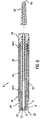
- FIG. 5 shows the stent 40' in place with the balloon angioplasty catheter 10, sheath 30 and guide wire 50 removed from the patient's arterial system.
- the stent delivery catheter system 5 is most valuable for stenting of stenoses in coronary arteries, it should be understood that it can be used in any vessel of the human body. It should also be noted that the system 5 can be readily used in tight arterial stenoses without requiring pre-dilatation by means of a separate, very low profile balloon angioplasty catheter. This capability for stent insertion without pre-dilatation saves both time and cost when placing stents into an arterial stenosis. It should also be noted that the elastic tubes 14P and 14D exactly center the stent 40 on the balloon 23. Also, the tube 14P prevents the stent 40 from moving in the proximal direction when the sheath 30 is pulled back.
- this invention can be used with either balloon expandable or self-expanding stents, and the balloon angioplasty catheter can be of either the "over-the-wire” design or of a "rapid-exchange” design.
- the most important capability of the stent delivery catheter system 5 is its ability to be pushed through even a very tight stenosis. This capability originates from several specific aspects of the design of the catheter system 5, namely, the small outside diameter of the tube 36 because of its thin wall, the extraordinarily gradual taper of the lubricity coated distal tip 24, the continuous outer surface from the tip 24 onto the tube 36, and the very high, distally directed push force achieved by means of the sheath 30 acting through the non-deployed stent 40.
- a "gradually tapered" distal tip 24 is obtained when the average slope of the tip relative to the longitudinal axis of the central lumen 19 at the distal portion of the balloon angioplasty catheter 10 is less than 3 degrees and never more than 10 degrees.
- the system 5 obtains its capability to push the distal tip 24 through a tight stenosis by a series of structures each of which is capable of significant pushability.
- This series of structures that provide excellent pushability for the stent delivery catheter system 5 are as follows:
- the pushability of the sheath 30 as transferred to a distal portion of the balloon angioplasty catheter 10 is very much greater than the pushability of the outer shaft 11 and inner shaft 12 by themselves. It should be noted that the design of the stent delivery catheter system 5 allows the sheath's distal tube 36 to be both very thin-walled and highly flexible, and no contribution to pushability is required of that structure.
- the thin-walled, flexible design of the tube 36 provides improved capability of the system 5 to place the stent 23 into a tight arterial stenosis because its flexibility improves passage through the tortuous vasculature of coronary arteries, and not requiring pushability from the tube 36 because of its thin wall, minimizes the outside diameter of the system 5 thus again improving the system's capability for placing the stent 23 into a tight stenosis.
- FIG. 6 is another embodiment of the distal section 8 of a stent delivery catheter system.
- the only difference between the embodiment of FIG. 6 compared with FIG. 1 is that in FIG. 6 the proximal and distal radiopaque marker bands 13P and 13D have been eliminated and the elastic bands 14P and 14D have been replaced with the proximal elastic band 60P and the distal elastic band 60D.
- the bands 60P and 60D would typically be longer than the bands 14P and 14D, and furthermore, the bands 60P and 60D would contain some material to make them radiopaque.
- powdered tungsten or tantalum could be placed into an elastomer such as silicone rubber or polyurethane to make the bands 60P and 60D both elastic and radiopaque.
- FIGS. 7, 8, 9 and 10 illustrate a stent delivery catheter system 70 which is a "rapid-exchange" design; i.e., the proximal exit of the guide wire 50 lies just proximal to the proximal end of the stent 40 as opposed to an "over-the-wire” design as shown in FIG. 1 where the guide wire 50 exits at the proximal end of the system 5.
- FIGS. 7 to 10 inclusive show the elastic radiopaque marker band 60P, the balloon 23, the stent 40, annular passageways 17 and 27 all of which elements are of the same design as shown for FIG. 1. The new aspects of the design shown in FIGS.
- the proximal portion of the rapid-exchange balloon angioplasty catheter is a dual lumen tube 63 that has a balloon access lumen 64 through which fluid can be injected or removed to inflate or deflate the balloon 23.
- a distal portion of the guide wire lumen 65 is used for inserting the guide wire 50 through a port 66.
- a very thin-walled short metal joining tube 73 is used to sealingly join the guide wire lumen 65 to the inner shaft 72.
- the outer shaft 71 is sealingly joined at its proximal end to the distal end of the dual-lumen tube 63.
- the entire structure of the system 70 that is distal to the metal joining tube 73 is identical in construction to the distal portion 8 of FIG. 6 except for the slot 62 in the sheath 61.
- slot 62 and key 67 cooperate to prevent the distal section of the sheath 61 from rotating about the dual-lumen tube 63.
- the length of the slot 62 is sufficient to allow the thin-walled tube 36 to be pulled back far enough to completely uncover the stent 40.
Abstract
Description
- This invention is in the field of catheters to place stents into a stenosis in a vessel of a human body.
- Intravascular stents are well known in the field of interventional cardiology for the treatment of arterial stenoses. When placed through the body's vascular system, most stents are mounted onto a balloon angioplasty catheter with or without a cylindrical sheath that covers the stent prior to stent deployment by balloon expansion at the site of a dilated stenosis. Self-expanding stents are almost always contained within a cylindrical sheath which is pulled back to release the stent. If a sheath is not used, the rough surface of the stent can damage or remove endothelial cells from the arterial wall as the outer surface of the stent rubs the inside walls of the curved coronary (or other) arteries. Without a sheath, the stent may also get caught on the guiding catheter during movement into or out of the body which can cause the stent to come off the delivery catheter and embolize into the vasculature. When a sheath is used, it can have a few disadvantages. A first disadvantage is that all prior art sheaths are tubes that have a uniform wall thickness and are secured only at the proximal end to the stent delivery catheter system. Therefore, in order to have a sufficient column strength, the sheath must be relatively thick-walled, throughout its entire length, which makes it stiff and bulky so that passage through tortuous coronary arteries can be difficult. Another disadvantage of prior art sheaths is that they have blunt distal ends which can be caught on an already deployed stent, a calcified piece of intimal dissected tissue or a tight stenosis. Still further, when secured only at the proximal end of a stent delivery catheter, the sheath often either uncovers the stent due to significant bending of the stent delivery catheter or the sheath advances too far distally beyond the distal end of the stent. Finally, because of the larger diameter, blunt end and stiffness of sheathed stent delivery systems or the rough outer surface of unsheathed stent delivery systems, pre-dilatation with another balloon angioplasty catheter is almost always required before stent implantation.
- Another disadvantage of existing stent delivery catheter systems that use either a conventional sheath or have stents mounted bare onto an inflatable balloon is that the distally directed push force for such stent delivery catheters comes only from the inner and outer shafts of the balloon angioplasty catheter on which the inflatable balloon is situated. Specifically, in no prior art device does the sheath contribute to the pushability of the stent delivery catheter system.
- EP-A-0720837-A1 describes a stent delivery catheter system that incorporates a balloon angioplasty catheter and a stent delivery catheter. The balloon angioplasty catheter has a distal portion and an inflatable balloon with a proximal and distal end, the balloon being located at the distal portion of the catheter. The stent is coaxially mounted around the balloon. The catheter further has a flexible, gradually tapered distal tip, with a central lumen through which a guide wire can be slidably moved. The system further comprises a sheath in the form of an elongated cylinder, coaxially located around the catheter, the sheath having a central and distal portion.
- Particular and preferred aspects of the invention are defined in the accompanying independent and dependent claims.
- An embodiment of the claimed invention provides a stent delivery catheter system for placing a stent within a stenosis in a vessel of a human body. The stent delivery catheter system utilizes a slideable sheath with a thin-walled distal portion that is situated coaxially over a stent that is placed onto a balloon located at the distal portion of a balloon angioplasty catheter.
- A central portion of the sheath is a comparatively thick-walled, flexible plastic tube or plastic plus wire tube whose distal end has an interior shoulder that engages a structure on the balloon angioplasty catheter at a point just proximal to the stent in order to exert a push force at that point onto a distal portion of the balloon angioplasty catheter . The distal portion of the sheath is a short (typically 2 to 5 cm long) tube that is very thin-walled and highly flexible. The purpose of using minimum wall thickness is to increase flexibility and decrease the outside diameter of the sheath in order to facilitate the pushing of the distal section of the stent delivery catheter system through a tight stenosis.
- The distal end of a central portion of the sheath has an interior shoulder which is capable of exerting a distally directed push force on the balloon angioplasty catheter at a point that is just proximal to the stent. This push force is then transferred through the non-deployed stent to a gradually tapered, highly flexible, lubricity coated distal tip of the balloon angioplasty catheter. The structure of a continuous outer surface extending backward from the distal tip and onto the distal section of the sheath, plus the lubricity coating of the outer surfaces of the distal tip and the sheath, plus the increased stent delivery catheter system pushability provided by the sheath and the stent itself makes it possible for the stent delivery catheter system to be pushed through even very tight stenoses. After the stent delivery catheter system is advanced over a guide wire so that the non-deployed stent is placed at the site of the stenoses, the sheath is then pulled back, the balloon is inflated and the stent is pushed radially outward resulting in dilatation of the stenosis. Thus the stent can be placed into even a tight stenosis without requiring pre-dilatation of that stenosis.
- A preferred embodiment of the sheath uses a thin-walled metal tube for the sheath's proximal section which constitutes approximately 80% of the length of the sheath.
- One embodiment of this invention has a proximal radiopaque marker band and a distal radiopaque marker band which are placed just proximal and just distal to the stent. Also, the stent can be advantageously placed between proximal and distal elastic tubes that go over the inflatable balloon and are situated just inside the radiopaque marker bands. The proximal elastic tube prevents the stent from being pulled backwards off the balloon when the sheath is pulled back prior to the stent deployment. Both radiopaque marker bands and both elastic tubes allow the push force exerted by the sheath to be transmitted to the catheter system's distal tip.
- Another embodiment of this invention utilizes only proximal and distal elastic tubes that surround the stent but without any radiopaque marker bands. However, for this embodiment, the elastic tubes include a highly radiopaque metal powder within the elastomer of the elastic tube so as to enhance the tube's radiopacity to assist in placing the stent at the site of the stenosis.
- Thus, an embodiment of the invention can provide a stent delivery catheter system that has a sheath with an interior shoulder located at the distal end of a central portion of the sheath which interior shoulder can exert a distally directed push force at a point just proximal to a non-deployed stent mounted onto a balloon at a distal portion of a balloon angioplasty catheter.
- An embodiment of the invention can have a distal portion of the sheath which is a thin-walled plastic or plastic plus wire tube thus minimizing the outer diameter of the sheath and increasing flexibility.
- An embodiment of the invention can utilize a non-deployed stent mounted onto a balloon at a distal portion of a balloon angioplasty catheter for transmitting a distally directed push force into a gradually tapered distal tip of a stent delivery catheter system.
- An embodiment of the invention can utilize the proximal end of a radiopaque marker band placed proximal to the stent as a point at which an interior shoulder of a sheath exerts a distally directed push force into a distal portion of a balloon angioplasty catheter.
- An embodiment of the invention can utilize the proximal end of a radiopaque elastic tube placed proximal to the stent as a point at which an interior shoulder of a sheath exerts a distally directed push force into a distal portion of a balloon angioplasty catheter.
- An embodiment of the invention can utilize elastic tubes placed just proximal and just distal to the stent as a means to carry a distally directed push force into a gradually tapered distal tip of the stent delivery catheter system.
- An embodiment of the invention can provide a stent delivery catheter system that utilizes a gradually tapered, lubricity coated, elastomer, highly flexible tip in order to push a distal section of the stent delivery catheter system through a tight stenosis.
- An embodiment of the invention can locate radiopaque marker bands and/or radiopaque elastic tubes placed just proximal and distal to a stent instead of placing such devices within an angioplasty balloon under the stent which placement within the balloon results in an increased outer diameter for the non-deployed stent.
- An embodiment of the invention can use elastic tubes placed just proximal and distal to a stent to prevent the stent from being dislodged from its centered position on an inflatable balloon.
- An embodiment of the invention can use elastic tubes placed just proximal and distal to a stent to prevent the stent from being dislodged from its post deployment position in the artery because the elastic tubes bring in the "wings" that would ordinarily form on the balloon after it is deflated, which "wings" could engage the deployed stent causing inadvertent stent displacement during removal of the balloon catheter.
- An embodiment of the invention can provide a stent delivery catheter system that can place a stent into a tight stenosis without first pre-dilating that tight stenosis.
- An embodiment of the invention can utilize a slotted central section of the sheath through which the guide wire exits that allows a rapid exchange capability for the stent delivery catheter system.
- Exemplary embodiments of the invention are described hereinafter, by way of example only, with reference to the accompanying drawings, in which:
- FIG. 1 is a longitudinal cross section of a stent delivery catheter system which illustrates the structure of the proximal, central and distal sections of a stent delivery catheter system.
- FIG. 2 shows a longitudinal cross section of the distal section of the stent delivery catheter system as it would be placed into an arterial stenosis prior to stent deployment.
- FIG. 3 is a longitudinal cross section of the distal section of the stent delivery catheter system with the sheath pulled back thus uncovering the stent.
- FIG. 4 shows a longitudinal cross section of the distal section of the stent delivery catheter system with the balloon inflated and the stent deployed outward so as to dilate the stenosis.
- FIG. 5 is a longitudinal cross section of the dilated stenosis showing the stent deployed radially outward and the stent delivery catheter system removed from the patient's artery.
- FIG. 6 is longitudinal cross section of the distal section of a stent delivery catheter system using radiopaque elastic tubes placed just proximal and distal to the stent.
- FIG. 7 is a longitudinal cross section of the stent delivery catheter system that illustrates a slotted sheath that allows a rapid exchange capability for the stent delivery catheter system.
- FIG. 8 is a highly enlarged transverse cross section of the rapid exchange stent delivery catheter system at section 8-8 of FIG. 7.
- FIG. 9 is a highly enlarged transverse cross section of the rapid exchange stent delivery catheter system at section 9-9 of FIG. 7.
- FIG. 10 is a highly enlarged transverse cross section of the rapid exchange stent delivery catheter system at section 10-10 of FIG. 7.
-
- FIG. 1 is a longitudinal cross section of a stent delivery catheter system 5 which is formed in three sections, namely; a proximal section 6, a center section 7 and a
distal section 8. The stent delivery catheter system 5 consists of aballoon angioplasty catheter 10, aslideable sheath 30, astent 40 and aguide wire 50. - The
balloon angioplasty catheter 10 consists of anouter shaft 11, aninner shaft 12, a proximalradiopaque marker band 13P, a distalradiopaque marker band 13D, a proximalelastic band 14P, a distalelastic band 14D and adistal elastomer tip 24 having a thin-walledcylindrical end 25. At the proximal end of theballoon angioplasty catheter 10 is a Luer fitting 20 through which theguide wire 50 can be passed into thecentral lumen 19. Also at the proximal end of theballoon angioplasty catheter 10 is aside arm 21 having a Luer fitting 22 and acentral passageway 26 that is in fluid communication with theannular passageway 17 that lies between the inner surface of theouter shaft 11 and the outer surface of theinner shaft 12. At thedistal section 8 of the stent delivery catheter system 5, theballoon angioplasty catheter 10 has a distal portion which includes anangioplasty balloon 23 whoseinterior chamber 29 is in fluid communication with theannular passageway 17 and thecentral lumen 26 of theside arm 21. Thus, a source of inflation fluid can be inserted into or removed from thelumen 26 to inflate and deflate theballoon 23. Mounted on theballoon 23 is a balloonexpandable stent 40 of any design that is well known in the art of balloon expandable stents. - The
slideable sheath 30 is situated coaxially about theballoon angioplasty catheter 10. At the system's proximal section 6, thesheath 30 has a Tuohy-Borst fitting consisting of amain body 31 having aside arm 39 with a Luer fitting 33; theside arm 39 having acentral lumen 38 that is in fluid communication with theannular passageway 27 that lies between the interior surface of thesheath 30 and the exterior surface of theouter shaft 11. The Tuohy-Borst fitting'smain body 31 has a threaded proximal end onto which anut 35 can be screwed on and off. Advancing thenut 35 compresses theelastomer gland 37 which causes a fluid seal to be made against the outer surface of theouter shaft 11. When such a fluid seal exists, no blood will leak from the Tuohy-Borst fitting and contrast liquid can be injected through thelumen 38 of theside arm 32 to flush air out of theannular passageway 27. - The
sheath 30 has a thin-walled metal tube 32 for most of its length, which length is approximately 110 cm. As shown at the system's central section 7, the distal end of thetube 32 is joined to the proximal end of aflexible tube 34 whose distal end (located at the system's distal section 8) has an interior shoulder that is in contact with the proximal end of the proximalradiopaque marker band 13P. A thin-walled, highly flexible,tube 36 is fixedly attached at its proximal end to the distal end of theflexible tube 34. The distal end of theflexible tube 36 is configured to move slideably over aproximal section 24P of thetip 24. Themetal tube 32 would typically be formed from stainless steel or Nitinol with a wall thickness between 0.01 and 0.1 mm. The outer diameter for thesheath 30 would typically be between 1.0 and 3.0 mm. Theelastic tube 36 would typically have a wall thickness between 0.01 and 0. 1 mm and would be made from any material typically used for catheters. Ideally thetube 36 would be formed from a plastic tube into which longitudinal metal wires are placed to prevent the tube from becoming wrinkled. Ideally these wires would be made from stainless steel or Nitinol. - The
flexible tube 34 would typically have twice the wall thickness of theelastic tube 36. The construction of thetube 34 would typically be a composite of a metal wire with a plastic material typically used for intravascular catheters. - The operation of the stent delivery catheter system 5 is best explained with the assistance of FIGS. 2, 3, 4 and 5.
- FIG. 2 shows the
distal section 8 already advanced over theguide wire 50 until thenon-deployed stent 40 is centered within anarterial stenosis 2 located within an artery 1. Theradiopaque marker bands stent 23 to center thestent 23 in thestenosis 2. It should be understood that the very gradually tapered shape of thetip 24 and the continuous outer surface of thetip 24 and the outer surface of thecylinder 36, each of which can have a lubricious outer coating, facilitates penetration through even a tight arterial stenosis. Thetip 24 can be made radiopaque by forming it from a compound of a dense metal such as tungsten into an elastomer such as polyurethane. - FIG. 3 shows the
sheath 30 pulled back so that thestent 40 is ready to be expanded. Pull back of thesheath 30 is accomplished by holding the Luer fitting 20 at the proximal portion of thestent delivery catheter 10 fixed while pulling back on thenut 35 of the Tuohy-Borst fitting at the proximal portion ofsheath 30. This is accomplished after thenut 35 is somewhat loosened so that thegland 37 slides easily over theouter shaft 11. - FIG. 4 shows an
inflated balloon 23' that causes the stent 40' to dilate the stenosis 2'. It should be noted that theelastomer tubes 14P' and 14D' become distorted when theballoon 23' is inflated. After theballoon 23' is deflated, thetubes 14P' and 14D' revert to their original shape as shown for thetubes - FIG. 5 shows the stent 40' in place with the
balloon angioplasty catheter 10,sheath 30 andguide wire 50 removed from the patient's arterial system. - Although the stent delivery catheter system 5 is most valuable for stenting of stenoses in coronary arteries, it should be understood that it can be used in any vessel of the human body. It should also be noted that the system 5 can be readily used in tight arterial stenoses without requiring pre-dilatation by means of a separate, very low profile balloon angioplasty catheter. This capability for stent insertion without pre-dilatation saves both time and cost when placing stents into an arterial stenosis. It should also be noted that the
elastic tubes stent 40 on theballoon 23. Also, thetube 14P prevents thestent 40 from moving in the proximal direction when thesheath 30 is pulled back. Still further it should be noted that this invention can be used with either balloon expandable or self-expanding stents, and the balloon angioplasty catheter can be of either the "over-the-wire" design or of a "rapid-exchange" design. - The most important capability of the stent delivery catheter system 5 is its ability to be pushed through even a very tight stenosis. This capability originates from several specific aspects of the design of the catheter system 5, namely, the small outside diameter of the
tube 36 because of its thin wall, the extraordinarily gradual taper of the lubricity coateddistal tip 24, the continuous outer surface from thetip 24 onto thetube 36, and the very high, distally directed push force achieved by means of thesheath 30 acting through thenon-deployed stent 40. A "gradually tapered"distal tip 24 is obtained when the average slope of the tip relative to the longitudinal axis of thecentral lumen 19 at the distal portion of theballoon angioplasty catheter 10 is less than 3 degrees and never more than 10 degrees. Optimally, an average slope for thetip 24 would be determined from a maximum radius of 0.6 mm at the tip's proximal end to a radius of 0.22 mm at the tips distal end. With a tip length of 15 mm, this gives an average slope for thetip 24 of 0.6-0.22/15 = 0.025 which is a slope angle of approximately 1.5 degrees relative to the longitudinal axis of thecentral lumen 17 of the distal portion of theballoon angioplasty catheter 10. Such a gradual taper greatly enhances the capability of the stent delivery catheter system 5 to penetrate through a tight stenosis. - The system 5 obtains its capability to push the
distal tip 24 through a tight stenosis by a series of structures each of which is capable of significant pushability. This series of structures that provide excellent pushability for the stent delivery catheter system 5 are as follows: - (1) The Tuohy-Borst fitting at the proximal end of the
sheath 30 which fitting lies outside the patient's body. - (2) The thin-walled, typically
stainless steel tube 32 that extends for most of the length of the stent delivery catheter system 5. - (3) The comparatively thick-walled,
flexible tube 34 that is typically a composite cylinder made from wire and an elastomeric plastic. - (4) The proximal
radiopaque marker band 13P whose outside diameter is greater than the inner diameter of the interior shoulder located at the distal end of theflexible tube 34. Therefore, the distal end of thetube 34 can effectively apply a distally directed push force onto the proximal end of the rigid, cylindricalradiopaque marker band 13P thus continuing the pushability of thesheath 30. It is at the intersection of the interior shoulder at the distal end of thetube 34 with the proximal end of the proximalradiopaque marker band 13P that the sheath pushability is transferred from the sheath to a distal portion of theballoon angioplasty catheter 10. - (5) The push force is next carried forward in the distal direction by the
proximal
elastic tube 14P which is adjacent to the proximalradiopaque marker band 13P and also adjacent to a proximal section of theballoon 23. - (6) The
stent 23 is the next structure that transmits the distally directed push force to thedistal tip 24. - (7) The distal
elastic tube 14D which is attached to a distal portion of theballoon 23 transmits the push force to the distalradiopaque marker band 13D. - (8) The distal
radiopaque marker band 13D, which can be molded into thedistal tip 24, is the last link in the pushability chain that enhances the capability of the stent delivery catheter system 5 to push thedistal tip 24 through a tight stenosis. -
- In summary, the pushability of the
sheath 30 as transferred to a distal portion of theballoon angioplasty catheter 10 is very much greater than the pushability of theouter shaft 11 andinner shaft 12 by themselves. It should be noted that the design of the stent delivery catheter system 5 allows the sheath'sdistal tube 36 to be both very thin-walled and highly flexible, and no contribution to pushability is required of that structure. - The thin-walled, flexible design of the
tube 36 provides improved capability of the system 5 to place thestent 23 into a tight arterial stenosis because its flexibility improves passage through the tortuous vasculature of coronary arteries, and not requiring pushability from thetube 36 because of its thin wall, minimizes the outside diameter of the system 5 thus again improving the system's capability for placing thestent 23 into a tight stenosis. - FIG. 6 is another embodiment of the
distal section 8 of a stent delivery catheter system. The only difference between the embodiment of FIG. 6 compared with FIG. 1 is that in FIG. 6 the proximal and distalradiopaque marker bands elastic bands elastic band 60P and the distal elastic band 60D. Thebands 60P and 60D would typically be longer than thebands bands 60P and 60D would contain some material to make them radiopaque. Typically, powdered tungsten or tantalum could be placed into an elastomer such as silicone rubber or polyurethane to make thebands 60P and 60D both elastic and radiopaque. - FIGS. 7, 8, 9 and 10 illustrate a stent
delivery catheter system 70 which is a "rapid-exchange" design; i.e., the proximal exit of theguide wire 50 lies just proximal to the proximal end of thestent 40 as opposed to an "over-the-wire" design as shown in FIG. 1 where theguide wire 50 exits at the proximal end of the system 5. FIGS. 7 to 10 inclusive show the elasticradiopaque marker band 60P, theballoon 23, thestent 40,annular passageways sheath 61 having a narrow elongated slot orkeyway 62 into which the key 67 is placed. The proximal portion of the rapid-exchange balloon angioplasty catheter is adual lumen tube 63 that has aballoon access lumen 64 through which fluid can be injected or removed to inflate or deflate theballoon 23. A distal portion of theguide wire lumen 65 is used for inserting theguide wire 50 through aport 66. A very thin-walled shortmetal joining tube 73 is used to sealingly join theguide wire lumen 65 to theinner shaft 72. Theouter shaft 71 is sealingly joined at its proximal end to the distal end of the dual-lumen tube 63. The entire structure of thesystem 70 that is distal to themetal joining tube 73 is identical in construction to thedistal portion 8 of FIG. 6 except for theslot 62 in thesheath 61. - It should be noted that the
slot 62 and key 67 cooperate to prevent the distal section of thesheath 61 from rotating about the dual-lumen tube 63. The length of theslot 62 is sufficient to allow the thin-walled tube 36 to be pulled back far enough to completely uncover thestent 40.
Claims (14)
- A stent delivery catheter system (5/70) for placing a stent (40/23) within a stenosis of a vessel in a human body, the system comprising:characterised in that:a flexible guide wire (50);a balloon angioplasty catheter (10) having a distal portion and having an inflatable balloon (23) which has a proximal end and a distal end, the balloon being located at the distal portion of the balloon angioplasty catheter and a stent (40) coaxially mounted around the balloon; the balloon angioplasty catheter (10) also having a flexible, gradually tapered, distal tip (24) which has a central lumen through which the guide wire can be slideably moved; anda sheath (30) generally in the form of an elongated cylinder that is coaxially located around the balloon angioplasty catheter (10), the sheath having a central portion and a distal portion,the distal portion of the sheath includes a thin-walled, highly flexible tube (36) which lies coaxially around the stent and the central portion of the sheath has a proximal end and a distal end, the highly flexible tube (36) having a proximal section that is fixedly attached to the distal end of the central portion of the sheath, the central portion also having an interior shoulder at its distal end which shoulder is situated inside the flexible tube (36), the shoulder at the distal end of the central portion of the sheath being adapted to provide a distally directed push force onto the distal portion of the balloon angioplasty catheter at a point proximal to the stent which push force is transmitted through the distal portion of the balloon angioplasty catheter which enables the distal tip to be pushed through the stenosis in the vessel of the human body.
- The system of claim 1 wherein the sheath has three cylindrical tube portions; a first portion being a proximal portion of the sheath and being in the form of a thin-walled metal tube (32) which has a distal end, the sheath also having a second portion which is the central portion that has a proximal end and a distal end, the central portion being joined at its proximal end to the distal end of the proximal portion of the sheath and the central portion being joined at its distal end to a third portion of the sheath which is the distal portion, the wall thickness of the central portion being greater than the wall thickness of either the proximal portion or distal portion of the sheath.
- The system of any preceding claim wherein the balloon angioplasty catheter (10) includes a proximal radiopaque marker band (13P) located proximal to the stent and a distal radiopaque marker band (13D) that lies distal to the stent, both radiopaque marker bands being located at the distal portion of the balloon angioplasty catheter (10).
- The system of claim 3 wherein the push force from the sheath is exerted against the proximal radiopaque marker band (13P).
- The system of claim 3 or claim 4 wherein the stent is centrally located between the proximal radiopaque marker band (13P) and the distal radiopaque marker band (13D).
- The system of any preceding claim wherein there is a proximal elastic band (14P) located just proximal to the stent and a distal elastic band (14D) located just distal to the stent, the distally directed push force from the sheath being exerted through both the proximal and distal elastic bands, the elastic bands being formed from an elastomeric plastic.
- The system of claim 6 wherein the proximal and distal elastic bands (14P/14D) include a radiopaque component that is placed within the elastomeric plastic of the elastic band.
- . The system of any preceding claim wherein the average slope of the gradually tapered distal tip (24) relative to a longitudinal axis of the central lumen of the distal portion of the balloon angioplasty catheter is less than 3 degrees.
- The system of any preceding claim wherein the average slope of the gradually tapered distal tip (24) relative to a longitudinal axis of the central lumen of the distal portion of the balloon angioplasty catheter (10) is less than approximately 1.5 degrees.
- The system of any preceding claim wherein the highly flexible tube (36) at the distal portion of the sheath is formed from a plastic material into which metal wires are inserted.
- The system of claim 10 wherein the metal of the metal wires is Nitinol.
- The system of claim 2 wherein the metal tube forming the proximal portion of the sheath is made from stainless steel.
- The system of claim 2 wherein the metal tube forming the proximal portion of the sheath is made from Nitinol.
- The system of any preceding claim wherein a narrow elongated slot is located in the side of the sheath which slot serves as a proximal exit port for the guide wire thus providing the stent delivery catheter system with rapid exchange capability.
Applications Claiming Priority (2)
| Application Number | Priority Date | Filing Date | Title |
|---|---|---|---|
| US828662 | 1997-03-31 | ||
| US08/828,662 US5792144A (en) | 1997-03-31 | 1997-03-31 | Stent delivery catheter system |
Publications (2)
| Publication Number | Publication Date |
|---|---|
| EP0868927A1 EP0868927A1 (en) | 1998-10-07 |
| EP0868927B1 true EP0868927B1 (en) | 2004-07-28 |
Family
ID=25252405
Family Applications (1)
| Application Number | Title | Priority Date | Filing Date |
|---|---|---|---|
| EP98302296A Expired - Lifetime EP0868927B1 (en) | 1997-03-31 | 1998-03-26 | Stent delivery catheter system |
Country Status (9)
| Country | Link |
|---|---|
| US (3) | US5792144A (en) |
| EP (1) | EP0868927B1 (en) |
| JP (1) | JPH10277159A (en) |
| KR (1) | KR100496127B1 (en) |
| AT (1) | ATE271895T1 (en) |
| AU (1) | AU725572B2 (en) |
| CA (1) | CA2232900C (en) |
| DE (1) | DE69825200T2 (en) |
| TW (1) | TW393323B (en) |
Cited By (1)
| Publication number | Priority date | Publication date | Assignee | Title |
|---|---|---|---|---|
| US7654264B2 (en) | 2006-07-18 | 2010-02-02 | Nellcor Puritan Bennett Llc | Medical tube including an inflatable cuff having a notched collar |
Families Citing this family (224)
| Publication number | Priority date | Publication date | Assignee | Title |
|---|---|---|---|---|
| CA2125258C (en) * | 1993-08-05 | 1998-12-22 | Dinah B Quiachon | Multicapsule intraluminal grafting system and method |
| SI0821920T2 (en) * | 1994-02-25 | 2006-08-31 | Fischell Robert | Stent |
| US6830577B2 (en) * | 1996-07-26 | 2004-12-14 | Kensey Nash Corporation | System and method of use for treating occluded vessels and diseased tissue |
| US5779721A (en) | 1996-07-26 | 1998-07-14 | Kensey Nash Corporation | System and method of use for revascularizing stenotic bypass grafts and other blood vessels |
| US6652546B1 (en) * | 1996-07-26 | 2003-11-25 | Kensey Nash Corporation | System and method of use for revascularizing stenotic bypass grafts and other occluded blood vessels |
| US6905505B2 (en) * | 1996-07-26 | 2005-06-14 | Kensey Nash Corporation | System and method of use for agent delivery and revascularizing of grafts and vessels |
| US6080170A (en) * | 1996-07-26 | 2000-06-27 | Kensey Nash Corporation | System and method of use for revascularizing stenotic bypass grafts and other occluded blood vessels |
| US6217585B1 (en) | 1996-08-16 | 2001-04-17 | Converge Medical, Inc. | Mechanical stent and graft delivery system |
| US5772669A (en) * | 1996-09-27 | 1998-06-30 | Scimed Life Systems, Inc. | Stent deployment catheter with retractable sheath |
| US6432127B1 (en) | 1996-10-11 | 2002-08-13 | Transvascular, Inc. | Devices for forming and/or maintaining connections between adjacent anatomical conduits |
| US5792144A (en) * | 1997-03-31 | 1998-08-11 | Cathco, Inc. | Stent delivery catheter system |
| US6019777A (en) * | 1997-04-21 | 2000-02-01 | Advanced Cardiovascular Systems, Inc. | Catheter and method for a stent delivery system |
| US6330884B1 (en) * | 1997-11-14 | 2001-12-18 | Transvascular, Inc. | Deformable scaffolding multicellular stent |
| JP3315931B2 (en) * | 1998-01-05 | 2002-08-19 | 旭光学工業株式会社 | Drainage tube indwelling device for endoscope |
| US6074398A (en) | 1998-01-13 | 2000-06-13 | Datascope Investment Corp. | Reduced diameter stent/graft deployment catheter |
| US6827730B1 (en) | 1998-01-13 | 2004-12-07 | Endovascular Technologies, Inc. | Reduced diameter stent/graft deployment catheter |
| EP0943300A1 (en) * | 1998-03-17 | 1999-09-22 | Medicorp S.A. | Reversible action endoprosthesis delivery device. |
| US20010001113A1 (en) | 1998-04-21 | 2001-05-10 | Florencia Lim | Balloon catheter |
| US6287314B1 (en) * | 1998-04-21 | 2001-09-11 | Advanced Cardiovascular Systems, Inc. | Stent deploying catheter system |
| US7004962B2 (en) * | 1998-07-27 | 2006-02-28 | Schneider (Usa), Inc. | Neuroaneurysm occlusion and delivery device and method of using same |
| US6261304B1 (en) | 1998-09-10 | 2001-07-17 | Percardia, Inc. | Delivery methods for left ventricular conduit |
| EP1112043B1 (en) | 1998-09-10 | 2006-04-05 | Percardia, Inc. | Tmr shunt |
| WO2000015147A1 (en) | 1998-09-10 | 2000-03-23 | Percardia, Inc. | Transmycardial shunt and its attachment mechanism, for left ventricular revascularization |
| US6196230B1 (en) | 1998-09-10 | 2001-03-06 | Percardia, Inc. | Stent delivery system and method of use |
| US6053913A (en) * | 1998-09-10 | 2000-04-25 | Tu; Lily Chen | Rapid exchange stented balloon catheter having ablation capabilities |
| US6254609B1 (en) | 1999-01-11 | 2001-07-03 | Scimed Life Systems, Inc. | Self-expanding stent delivery system with two sheaths |
| US6325825B1 (en) * | 1999-04-08 | 2001-12-04 | Cordis Corporation | Stent with variable wall thickness |
| US6375676B1 (en) * | 1999-05-17 | 2002-04-23 | Advanced Cardiovascular Systems, Inc. | Self-expanding stent with enhanced delivery precision and stent delivery system |
| US6270521B1 (en) * | 1999-05-21 | 2001-08-07 | Cordis Corporation | Stent delivery catheter system for primary stenting |
| AU2004202046B2 (en) * | 1999-05-21 | 2006-09-14 | Cordis Corporation | Stent delivery catheter system for primary stenting |
| US6315790B1 (en) * | 1999-06-07 | 2001-11-13 | Scimed Life Systems, Inc. | Radiopaque marker bands |
| US6302892B1 (en) | 1999-08-04 | 2001-10-16 | Percardia, Inc. | Blood flow conduit delivery system and method of use |
| US6638237B1 (en) | 1999-08-04 | 2003-10-28 | Percardia, Inc. | Left ventricular conduits and methods for delivery |
| US6179810B1 (en) * | 1999-08-17 | 2001-01-30 | Advanced Cardiovascular Systems, Inc. | Catheter with a flexible and pushable shaft |
| US6533806B1 (en) | 1999-10-01 | 2003-03-18 | Scimed Life Systems, Inc. | Balloon yielded delivery system and endovascular graft design for easy deployment |
| JP2003521971A (en) * | 1999-10-12 | 2003-07-22 | ウィル,アラン アール | Method and apparatus for protecting passages in the body |
| US6287291B1 (en) * | 1999-11-09 | 2001-09-11 | Advanced Cardiovascular Systems, Inc. | Protective sheath for catheters |
| US7758624B2 (en) * | 2000-11-13 | 2010-07-20 | C. R. Bard, Inc. | Implant delivery device |
| US20060069423A1 (en) * | 1999-11-22 | 2006-03-30 | Fischell David R | Means and method for treating an intimal dissection after stent implantation |
| US7011673B2 (en) * | 1999-11-22 | 2006-03-14 | Fischell Robert E | Stent delivery system with a fixed guide wire |
| US6375660B1 (en) * | 1999-11-22 | 2002-04-23 | Cordis Corporation | Stent delivery system with a fixed guide wire |
| AU3441001A (en) * | 1999-12-01 | 2001-06-12 | Advanced Cardiovascular Systems Inc. | Nitinol alloy design and composition for vascular stents |
| US6280466B1 (en) * | 1999-12-03 | 2001-08-28 | Teramed Inc. | Endovascular graft system |
| US6443979B1 (en) | 1999-12-20 | 2002-09-03 | Advanced Cardiovascular Systems, Inc. | Expandable stent delivery sheath and method of use |
| US20040098085A1 (en) * | 2000-02-11 | 2004-05-20 | Ricci Donald R. | Stent delivery system and method of use |
| US6854467B2 (en) | 2000-05-04 | 2005-02-15 | Percardia, Inc. | Methods and devices for delivering a ventricular stent |
| WO2001089421A2 (en) | 2000-05-22 | 2001-11-29 | Orbus Medical Technologies Inc. | Self-expanding stent |
| US6540775B1 (en) * | 2000-06-30 | 2003-04-01 | Cordis Corporation | Ultraflexible open cell stent |
| US20020016597A1 (en) * | 2000-08-02 | 2002-02-07 | Dwyer Clifford J. | Delivery apparatus for a self-expanding stent |
| US6773446B1 (en) | 2000-08-02 | 2004-08-10 | Cordis Corporation | Delivery apparatus for a self-expanding stent |
| US7976648B1 (en) | 2000-11-02 | 2011-07-12 | Abbott Cardiovascular Systems Inc. | Heat treatment for cold worked nitinol to impart a shape setting capability without eventually developing stress-induced martensite |
| US6602272B2 (en) | 2000-11-02 | 2003-08-05 | Advanced Cardiovascular Systems, Inc. | Devices configured from heat shaped, strain hardened nickel-titanium |
| US6855161B2 (en) | 2000-12-27 | 2005-02-15 | Advanced Cardiovascular Systems, Inc. | Radiopaque nitinol alloys for medical devices |
| US7128757B2 (en) * | 2000-12-27 | 2006-10-31 | Advanced Cardiovascular, Inc. | Radiopaque and MRI compatible nitinol alloys for medical devices |
| US20060086440A1 (en) * | 2000-12-27 | 2006-04-27 | Boylan John F | Nitinol alloy design for improved mechanical stability and broader superelastic operating window |
| US6699274B2 (en) * | 2001-01-22 | 2004-03-02 | Scimed Life Systems, Inc. | Stent delivery system and method of manufacturing same |
| US6689151B2 (en) * | 2001-01-25 | 2004-02-10 | Scimed Life Systems, Inc. | Variable wall thickness for delivery sheath housing |
| US6660031B2 (en) | 2001-04-11 | 2003-12-09 | Scimed Life Systems, Inc. | Multi-length delivery system |
| US20020198559A1 (en) * | 2001-06-26 | 2002-12-26 | Bhavesh Mistry | Radiopaque balloon |
| US6676693B1 (en) * | 2001-06-27 | 2004-01-13 | Advanced Cardiovascular Systems, Inc. | Apparatus and method for delivering a self-expanding stent |
| JP4512362B2 (en) * | 2001-07-06 | 2010-07-28 | アンギオメット ゲゼルシャフト ミット ベシュレンクテル ハフツング ウント コムパニー メディツィンテヒニク コマンデイトゲゼルシャフト | Self-expanding stent rapid pusher assembly and delivery system with stent replacement configuration |
| US6679909B2 (en) * | 2001-07-31 | 2004-01-20 | Advanced Cardiovascular Systems, Inc. | Rapid exchange delivery system for self-expanding stent |
| US7175655B1 (en) * | 2001-09-17 | 2007-02-13 | Endovascular Technologies, Inc. | Avoiding stress-induced martensitic transformation in nickel titanium alloys used in medical devices |
| US6863683B2 (en) | 2001-09-19 | 2005-03-08 | Abbott Laboratoris Vascular Entities Limited | Cold-molding process for loading a stent onto a stent delivery system |
| US6863678B2 (en) | 2001-09-19 | 2005-03-08 | Advanced Cardiovascular Systems, Inc. | Catheter with a multilayered shaft section having a polyimide layer |
| GB0123633D0 (en) * | 2001-10-02 | 2001-11-21 | Angiomed Ag | Stent delivery system |
| EP1441669B1 (en) | 2001-11-09 | 2009-03-25 | AngioScore, Inc. | Baloon catheter with non-deployable stent |
| US20040111108A1 (en) | 2001-11-09 | 2004-06-10 | Farnan Robert C. | Balloon catheter with non-deployable stent |
| US7892273B2 (en) | 2001-12-03 | 2011-02-22 | Xtent, Inc. | Custom length stent apparatus |
| US7351255B2 (en) | 2001-12-03 | 2008-04-01 | Xtent, Inc. | Stent delivery apparatus and method |
| US7182779B2 (en) * | 2001-12-03 | 2007-02-27 | Xtent, Inc. | Apparatus and methods for positioning prostheses for deployment from a catheter |
| US20040186551A1 (en) | 2003-01-17 | 2004-09-23 | Xtent, Inc. | Multiple independent nested stent structures and methods for their preparation and deployment |
| US7137993B2 (en) | 2001-12-03 | 2006-11-21 | Xtent, Inc. | Apparatus and methods for delivery of multiple distributed stents |
| US7147656B2 (en) | 2001-12-03 | 2006-12-12 | Xtent, Inc. | Apparatus and methods for delivery of braided prostheses |
| US20030135256A1 (en) * | 2002-01-14 | 2003-07-17 | Gallagher Brendan P. | Stent delivery system |
| US7360540B2 (en) * | 2002-01-23 | 2008-04-22 | Indian Ocean Medical Inc. | Endotracheal tube which permits accurate determination of mucosal pressure |
| US7169170B2 (en) | 2002-02-22 | 2007-01-30 | Cordis Corporation | Self-expanding stent delivery system |
| ATE281800T1 (en) * | 2002-09-09 | 2004-11-15 | Abbott Lab Vascular Entpr Ltd | SYSTEM FOR INSERTING A SELF-EXPANDING STENT |
| CA2512203C (en) | 2002-12-02 | 2012-10-23 | Gi Dynamics, Inc. | Bariatric sleeve |
| US7025791B2 (en) * | 2002-12-02 | 2006-04-11 | Gi Dynamics, Inc. | Bariatric sleeve |
| US7608114B2 (en) | 2002-12-02 | 2009-10-27 | Gi Dynamics, Inc. | Bariatric sleeve |
| US7678068B2 (en) | 2002-12-02 | 2010-03-16 | Gi Dynamics, Inc. | Atraumatic delivery devices |
| US7695446B2 (en) | 2002-12-02 | 2010-04-13 | Gi Dynamics, Inc. | Methods of treatment using a bariatric sleeve |
| US7766973B2 (en) | 2005-01-19 | 2010-08-03 | Gi Dynamics, Inc. | Eversion resistant sleeves |
| GB0327306D0 (en) * | 2003-11-24 | 2003-12-24 | Angiomed Gmbh & Co | Catheter device |
| JP4757187B2 (en) * | 2003-01-15 | 2011-08-24 | アンジオメト・ゲーエムベーハー・ウント・コンパニー・メディツィンテクニク・カーゲー | Tube surgery equipment |
| US8080026B2 (en) | 2003-01-21 | 2011-12-20 | Angioscore, Inc. | Apparatus and methods for treating hardened vascular lesions |
| JP2006518625A (en) * | 2003-02-14 | 2006-08-17 | サルヴィアック・リミテッド | Stent delivery and placement system |
| US20040215229A1 (en) * | 2003-04-22 | 2004-10-28 | Medtronic Ave, Inc. | Stent delivery system and method |
| US7942892B2 (en) | 2003-05-01 | 2011-05-17 | Abbott Cardiovascular Systems Inc. | Radiopaque nitinol embolic protection frame |
| US8034048B2 (en) * | 2003-05-05 | 2011-10-11 | Boston Scientific Scimed, Inc. | Tissue patches and related delivery systems and methods |
| US7416546B2 (en) * | 2003-05-05 | 2008-08-26 | Boston Scientific Scimed, Inc. | Tissue patches and related delivery systems and methods |
| US20050049666A1 (en) * | 2003-08-26 | 2005-03-03 | Chien Thomas Yung-Hui | Stent delivery system |
| US7780716B2 (en) * | 2003-09-02 | 2010-08-24 | Abbott Laboratories | Delivery system for a medical device |
| DE602004018665D1 (en) * | 2003-09-02 | 2009-02-05 | Abbott Lab | Delivery system for a medical device |
| US7794489B2 (en) * | 2003-09-02 | 2010-09-14 | Abbott Laboratories | Delivery system for a medical device |
| US7763063B2 (en) | 2003-09-03 | 2010-07-27 | Bolton Medical, Inc. | Self-aligning stent graft delivery system, kit, and method |
| US20080264102A1 (en) * | 2004-02-23 | 2008-10-30 | Bolton Medical, Inc. | Sheath Capture Device for Stent Graft Delivery System and Method for Operating Same |
| US20070198078A1 (en) | 2003-09-03 | 2007-08-23 | Bolton Medical, Inc. | Delivery system and method for self-centering a Proximal end of a stent graft |
| US8500792B2 (en) | 2003-09-03 | 2013-08-06 | Bolton Medical, Inc. | Dual capture device for stent graft delivery system and method for capturing a stent graft |
| US11596537B2 (en) | 2003-09-03 | 2023-03-07 | Bolton Medical, Inc. | Delivery system and method for self-centering a proximal end of a stent graft |
| US9198786B2 (en) | 2003-09-03 | 2015-12-01 | Bolton Medical, Inc. | Lumen repair device with capture structure |
| US11259945B2 (en) | 2003-09-03 | 2022-03-01 | Bolton Medical, Inc. | Dual capture device for stent graft delivery system and method for capturing a stent graft |
| US8292943B2 (en) | 2003-09-03 | 2012-10-23 | Bolton Medical, Inc. | Stent graft with longitudinal support member |
| DE10346200A1 (en) * | 2003-09-30 | 2005-05-04 | Jotec Gmbh | Delivery system with a self-expanding stent |
| US8057533B2 (en) * | 2003-10-29 | 2011-11-15 | Boston Scientific Scimed, Inc. | Apparatus with visual marker for guiding deployment of implantable prosthesis |
| US7867271B2 (en) | 2003-11-20 | 2011-01-11 | Advanced Cardiovascular Systems, Inc. | Rapid-exchange delivery systems for self-expanding stents |
| US8057420B2 (en) | 2003-12-09 | 2011-11-15 | Gi Dynamics, Inc. | Gastrointestinal implant with drawstring |
| EP1708641A1 (en) | 2003-12-09 | 2006-10-11 | GI Dynamics, Inc. | Intestinal sleeve |
| US7326236B2 (en) | 2003-12-23 | 2008-02-05 | Xtent, Inc. | Devices and methods for controlling and indicating the length of an interventional element |
| US7449027B2 (en) * | 2004-03-29 | 2008-11-11 | Cook Incorporated | Modifying fluid flow in a body vessel lumen to promote intraluminal flow-sensitive processes |
| US7323006B2 (en) | 2004-03-30 | 2008-01-29 | Xtent, Inc. | Rapid exchange interventional devices and methods |
| ATE468830T1 (en) | 2004-03-31 | 2010-06-15 | Wilson Cook Medical Inc | STENT DELIVERY SYSTEM |
| US20050288766A1 (en) | 2004-06-28 | 2005-12-29 | Xtent, Inc. | Devices and methods for controlling expandable prostheses during deployment |
| US8317859B2 (en) | 2004-06-28 | 2012-11-27 | J.W. Medical Systems Ltd. | Devices and methods for controlling expandable prostheses during deployment |
| EP1768618B1 (en) | 2004-07-09 | 2011-04-20 | GI Dynamics, Inc. | Devices for placing a gastrointestinal sleeve |
| AU2005287010B2 (en) | 2004-09-17 | 2010-04-15 | Gi Dynamics, Inc. | Gastrointestinal anchor |
| JP2006130064A (en) * | 2004-11-05 | 2006-05-25 | National Cardiovascular Center | Stent delivery system |
| US20080058926A1 (en) * | 2004-12-22 | 2008-03-06 | Stephen Solomon | Percutaneous breast and buttock modification |
| US20060173484A1 (en) * | 2004-12-22 | 2006-08-03 | Stephen Solomon | Percutaneous breast and buttock modification |
| US7771382B2 (en) | 2005-01-19 | 2010-08-10 | Gi Dynamics, Inc. | Resistive anti-obesity devices |
| DE102005003632A1 (en) | 2005-01-20 | 2006-08-17 | Fraunhofer-Gesellschaft zur Förderung der angewandten Forschung e.V. | Catheter for the transvascular implantation of heart valve prostheses |
| US20060178721A1 (en) * | 2005-02-10 | 2006-08-10 | Advanced Cardiovascular Systems, Inc. | Stent delivery balloon catheter having improved stent retention |
| EP1871292B1 (en) | 2005-04-04 | 2019-10-23 | Flexible Stenting Solutions, Inc. | Flexible stent |
| US10076641B2 (en) | 2005-05-11 | 2018-09-18 | The Spectranetics Corporation | Methods and systems for delivering substances into luminal walls |
| AU2006247571A1 (en) * | 2005-05-13 | 2006-11-23 | Cook Incorporated | Medical device delivery systems that facilitate medical device placement in the presence of ultrasonic waves |
| US7976488B2 (en) | 2005-06-08 | 2011-07-12 | Gi Dynamics, Inc. | Gastrointestinal anchor compliance |
| WO2007005799A1 (en) * | 2005-06-30 | 2007-01-11 | Abbott Laboratories | Delivery system for a medical device |
| US20070049801A1 (en) * | 2005-08-24 | 2007-03-01 | Lamport Ronald B | Endoscope accessory |
| US9011473B2 (en) | 2005-09-07 | 2015-04-21 | Ulthera, Inc. | Dissection handpiece and method for reducing the appearance of cellulite |
| US9358033B2 (en) | 2005-09-07 | 2016-06-07 | Ulthera, Inc. | Fluid-jet dissection system and method for reducing the appearance of cellulite |
| US10548659B2 (en) | 2006-01-17 | 2020-02-04 | Ulthera, Inc. | High pressure pre-burst for improved fluid delivery |
| US9486274B2 (en) | 2005-09-07 | 2016-11-08 | Ulthera, Inc. | Dissection handpiece and method for reducing the appearance of cellulite |
| US8518069B2 (en) | 2005-09-07 | 2013-08-27 | Cabochon Aesthetics, Inc. | Dissection handpiece and method for reducing the appearance of cellulite |
| US9254211B2 (en) * | 2005-10-06 | 2016-02-09 | Cordis Corporation | Stent delivery system using a steerable guide wire |
| JP2009512515A (en) | 2005-10-19 | 2009-03-26 | パルサー バスキュラー インコーポレイテッド | Methods and systems for clipping within a vessel and repairing intraluminal and tissue defects. |
| US8545530B2 (en) * | 2005-10-19 | 2013-10-01 | Pulsar Vascular, Inc. | Implantable aneurysm closure systems and methods |
| US9248317B2 (en) | 2005-12-02 | 2016-02-02 | Ulthera, Inc. | Devices and methods for selectively lysing cells |
| US7885793B2 (en) | 2007-05-22 | 2011-02-08 | International Business Machines Corporation | Method and system for developing a conceptual model to facilitate generating a business-aligned information technology solution |
| US11026822B2 (en) | 2006-01-13 | 2021-06-08 | C. R. Bard, Inc. | Stent delivery system |
| CA2836094C (en) | 2006-01-13 | 2016-09-06 | C.R. Bard, Inc. | Stent delivery system |
| US8235969B2 (en) * | 2006-03-06 | 2012-08-07 | Boston Scientific Scimed, Inc. | Medical device shaft designs |
| JP2009530060A (en) | 2006-03-20 | 2009-08-27 | エックステント・インコーポレーテッド | Apparatus and method for deploying connected prosthetic segments |
| US8333000B2 (en) | 2006-06-19 | 2012-12-18 | Advanced Cardiovascular Systems, Inc. | Methods for improving stent retention on a balloon catheter |
| US7819836B2 (en) | 2006-06-23 | 2010-10-26 | Gi Dynamics, Inc. | Resistive anti-obesity devices |
| US8382738B2 (en) | 2006-06-30 | 2013-02-26 | Abbott Cardiovascular Systems, Inc. | Balloon catheter tapered shaft having high strength and flexibility and method of making same |
| US7906066B2 (en) | 2006-06-30 | 2011-03-15 | Abbott Cardiovascular Systems, Inc. | Method of making a balloon catheter shaft having high strength and flexibility |
| GB0615658D0 (en) | 2006-08-07 | 2006-09-13 | Angiomed Ag | Hand-held actuator device |
| EP2218425B1 (en) * | 2006-09-08 | 2012-05-09 | Edwards Lifesciences Corporation | Integrated heart valve delivery system |
| US20080077223A1 (en) * | 2006-09-21 | 2008-03-27 | Fischell Robert E | Stent delivery system with improved deliverabilty features |
| US20080132906A1 (en) * | 2006-11-30 | 2008-06-05 | William Cook Europe Aps | Pusher sheath and deployment device |
| US20080140022A1 (en) * | 2006-12-08 | 2008-06-12 | Warsaw Orthopedic, Inc. | Coated Cannula with Protective Tip for Insertion Into a Patient |
| US20080199510A1 (en) | 2007-02-20 | 2008-08-21 | Xtent, Inc. | Thermo-mechanically controlled implants and methods of use |
| US8801647B2 (en) | 2007-02-22 | 2014-08-12 | Gi Dynamics, Inc. | Use of a gastrointestinal sleeve to treat bariatric surgery fistulas and leaks |
| US8486132B2 (en) | 2007-03-22 | 2013-07-16 | J.W. Medical Systems Ltd. | Devices and methods for controlling expandable prostheses during deployment |
| US7896915B2 (en) | 2007-04-13 | 2011-03-01 | Jenavalve Technology, Inc. | Medical device for treating a heart valve insufficiency |
| US7776080B2 (en) * | 2007-04-25 | 2010-08-17 | Abbott Cardiovascualr Systems Inc. | Stent delivery catheter system and method of implanting a self-expanding stent with embolic protection |
| GB0713497D0 (en) | 2007-07-11 | 2007-08-22 | Angiomed Ag | Device for catheter sheath retraction |
| US7988723B2 (en) | 2007-08-02 | 2011-08-02 | Flexible Stenting Solutions, Inc. | Flexible stent |
| US8439940B2 (en) | 2010-12-22 | 2013-05-14 | Cabochon Aesthetics, Inc. | Dissection handpiece with aspiration means for reducing the appearance of cellulite |
| US8114144B2 (en) | 2007-10-17 | 2012-02-14 | Abbott Cardiovascular Systems Inc. | Rapid-exchange retractable sheath self-expanding delivery system with incompressible inner member and flexible distal assembly |
| US8403885B2 (en) | 2007-12-17 | 2013-03-26 | Abbott Cardiovascular Systems Inc. | Catheter having transitioning shaft segments |
| ES2903231T3 (en) | 2008-02-26 | 2022-03-31 | Jenavalve Tech Inc | Stent for positioning and anchoring a valve prosthesis at an implantation site in a patient's heart |
| US9044318B2 (en) | 2008-02-26 | 2015-06-02 | Jenavalve Technology Gmbh | Stent for the positioning and anchoring of a valvular prosthesis |
| US9101503B2 (en) | 2008-03-06 | 2015-08-11 | J.W. Medical Systems Ltd. | Apparatus having variable strut length and methods of use |
| CN107961098A (en) * | 2008-06-30 | 2018-04-27 | 波顿医疗公司 | System and method for abdominal aneurvsm |
| EP2293838B1 (en) | 2008-07-01 | 2012-08-08 | Endologix, Inc. | Catheter system |
| JP5791048B2 (en) * | 2008-09-05 | 2015-10-07 | パルサー バスキュラー インコーポレイテッド | System and method for supporting or occluding a physiological opening or cavity |
| US9149376B2 (en) * | 2008-10-06 | 2015-10-06 | Cordis Corporation | Reconstrainable stent delivery system |
| US8052638B2 (en) | 2008-11-26 | 2011-11-08 | Abbott Cardiovascular Systems, Inc. | Robust multi-layer balloon |
| US8444608B2 (en) | 2008-11-26 | 2013-05-21 | Abbott Cardivascular Systems, Inc. | Robust catheter tubing |
| AU2010223953B2 (en) | 2009-03-13 | 2014-05-01 | Bolton Medical, Inc. | System and method for deploying an endoluminal prosthesis at a surgical site |
| WO2010124286A1 (en) * | 2009-04-24 | 2010-10-28 | Flexible Stenting Solutions, Inc. | Flexible devices |
| US9358064B2 (en) | 2009-08-07 | 2016-06-07 | Ulthera, Inc. | Handpiece and methods for performing subcutaneous surgery |
| US11096708B2 (en) | 2009-08-07 | 2021-08-24 | Ulthera, Inc. | Devices and methods for performing subcutaneous surgery |
| EP3300673A3 (en) | 2009-09-04 | 2018-10-03 | Pulsar Vascular, Inc. | Systems for enclosing an anatomical opening |
| WO2011036850A1 (en) * | 2009-09-25 | 2011-03-31 | 株式会社 京都医療設計 | Medical catheter device |
| US8372133B2 (en) * | 2009-10-05 | 2013-02-12 | 480 Biomedical, Inc. | Polymeric implant delivery system |
| US20110106234A1 (en) * | 2009-10-30 | 2011-05-05 | Axel Grandt | Interluminal medical treatment devices and methods |
| PL2558154T3 (en) * | 2010-04-16 | 2020-11-30 | Clearpoint Neuro, Inc. | Mri surgical systems including mri-compatible surgical cannulae for transferring a substance to and/or from a patient |
| EP2380604A1 (en) | 2010-04-19 | 2011-10-26 | InnoRa Gmbh | Improved coating formulations for scoring or cutting balloon catheters |
| US10856978B2 (en) * | 2010-05-20 | 2020-12-08 | Jenavalve Technology, Inc. | Catheter system |
| US11278406B2 (en) * | 2010-05-20 | 2022-03-22 | Jenavalve Technology, Inc. | Catheter system for introducing an expandable heart valve stent into the body of a patient, insertion system with a catheter system and medical device for treatment of a heart valve defect |
| CN103002833B (en) | 2010-05-25 | 2016-05-11 | 耶拿阀门科技公司 | Artificial heart valve and comprise artificial heart valve and support through conduit carry interior prosthese |
| US8632559B2 (en) | 2010-09-21 | 2014-01-21 | Angioscore, Inc. | Method and system for treating valve stenosis |
| GB201017834D0 (en) | 2010-10-21 | 2010-12-01 | Angiomed Ag | System to deliver a bodily implant |
| FR2970864B1 (en) * | 2011-02-01 | 2015-01-02 | Stentys | DELIVERY SYSTEM FOR A STENT |
| CN103561807B (en) * | 2011-03-01 | 2015-11-25 | 恩朵罗杰克斯股份有限公司 | Conduit system and using method thereof |
| US9101507B2 (en) | 2011-05-18 | 2015-08-11 | Ralph F. Caselnova | Apparatus and method for proximal-to-distal endoluminal stent deployment |
| WO2012162661A1 (en) | 2011-05-26 | 2012-11-29 | Abbott Cardiovascular Systems Inc. | Through tip for a catheter |
| EP2713905B1 (en) | 2011-06-03 | 2022-03-16 | Pulsar Vascular, Inc. | Systems for enclosing an anatomical opening, including shock absorbing aneurysm devices |
| CA2837420C (en) | 2011-06-03 | 2019-07-09 | Pulsar Vascular, Inc. | Aneurysm devices with additional anchoring mechanisms and associated systems and methods |
| ES2809210T3 (en) | 2011-10-05 | 2021-03-03 | Pulsar Vascular Inc | Systems and devices for wrapping an anatomical opening |
| EP3281608B1 (en) | 2012-02-10 | 2020-09-16 | CVDevices, LLC | Medical product comprising a frame and visceral pleura |
| US8998970B2 (en) | 2012-04-12 | 2015-04-07 | Bolton Medical, Inc. | Vascular prosthetic delivery device and method of use |
| WO2013169380A1 (en) | 2012-05-10 | 2013-11-14 | Pulsar Vascular, Inc. | Coil-tipped aneurysm devices |
| US9233015B2 (en) | 2012-06-15 | 2016-01-12 | Trivascular, Inc. | Endovascular delivery system with an improved radiopaque marker scheme |
| US8684963B2 (en) | 2012-07-05 | 2014-04-01 | Abbott Cardiovascular Systems Inc. | Catheter with a dual lumen monolithic shaft |
| WO2014107600A1 (en) * | 2013-01-03 | 2014-07-10 | Summit Access, LLC | Composite wires for use in medical procedures and associated methods |
| CA2900862C (en) | 2013-02-11 | 2017-10-03 | Cook Medical Technologies Llc | Expandable support frame and medical device |
| US9439751B2 (en) | 2013-03-15 | 2016-09-13 | Bolton Medical, Inc. | Hemostasis valve and delivery systems |
| US11759186B2 (en) * | 2018-06-08 | 2023-09-19 | David S. Goldsmith | Ductus side-entry and prosthetic disorder response systems |
| US9867694B2 (en) | 2013-08-30 | 2018-01-16 | Jenavalve Technology Inc. | Radially collapsible frame for a prosthetic valve and method for manufacturing such a frame |
| US9891296B2 (en) | 2013-09-13 | 2018-02-13 | MRI Interventions, Inc. | Intrabody fluid transfer devices, systems and methods |
| US10117668B2 (en) | 2013-10-08 | 2018-11-06 | The Spectranetics Corporation | Balloon catheter with non-deployable stent having improved stability |
| US9974675B2 (en) * | 2014-04-04 | 2018-05-22 | W. L. Gore & Associates, Inc. | Delivery and deployment systems for bifurcated stent grafts |
| KR101663754B1 (en) * | 2014-06-02 | 2016-10-10 | 이상협 | Apparatus for prosthesis insertion |
| WO2016049262A1 (en) * | 2014-09-25 | 2016-03-31 | Merit Medical Systems, Inc. | Coated balloons and coated balloon assemblies and related methods of use and manufacture |
| USD782658S1 (en) | 2015-02-02 | 2017-03-28 | Indian Ocean Medical Inc. | Airway device |
| CN107530168B (en) | 2015-05-01 | 2020-06-09 | 耶拿阀门科技股份有限公司 | Device and method with reduced pacemaker ratio in heart valve replacement |
| US10603195B1 (en) * | 2015-05-20 | 2020-03-31 | Paul Sherburne | Radial expansion and contraction features of medical devices |
| WO2017004265A1 (en) | 2015-06-30 | 2017-01-05 | Endologix, Inc. | Locking assembly for coupling guidewire to delivery system |
| KR101598508B1 (en) | 2015-11-09 | 2016-02-29 | 김영미 | Assembly Toys and Member of Assembly Toys |
| WO2017142698A1 (en) | 2016-02-17 | 2017-08-24 | MRI Interventions, Inc. | Intrabody surgical fluid transfer assemblies with adjustable exposed cannula to needle tip length, related systems and methods |
| KR101673471B1 (en) | 2016-04-08 | 2016-11-07 | 김영미 | Magnetic mounting means of Assembly Toys |
| US10406011B2 (en) * | 2016-04-28 | 2019-09-10 | Medtronic Vascular, Inc. | Implantable medical device delivery system |
| WO2017195125A1 (en) | 2016-05-13 | 2017-11-16 | Jenavalve Technology, Inc. | Heart valve prosthesis delivery system and method for delivery of heart valve prosthesis with introducer sheath and loading system |
| US20180056051A1 (en) * | 2016-08-31 | 2018-03-01 | Angioscore, Inc. | Apparatus and methods for treating hardened vascular lesions |
| CN110392557A (en) | 2017-01-27 | 2019-10-29 | 耶拿阀门科技股份有限公司 | Heart valve simulation |
| US11253237B2 (en) | 2018-05-09 | 2022-02-22 | Clearpoint Neuro, Inc. | MRI compatible intrabody fluid transfer systems and related devices and methods |
| EP3781074A1 (en) | 2018-05-09 | 2021-02-24 | ClearPoint Neuro, Inc. | Mri compatible intrabody fluid transfer systems and related devices and methods |
| US11684750B2 (en) | 2019-10-08 | 2023-06-27 | Clearpoint Neuro, Inc. | Extension tube assembly and related medical fluid transfer systems and methods |
| GB201917184D0 (en) * | 2019-11-26 | 2020-01-08 | Univ Sheffield | Guiding device for a vascular catheter |
| CN113413359B (en) * | 2021-06-24 | 2023-08-29 | 南通市中医院 | Traditional Chinese medicine drainage strip for chronic mastitis sinus, traditional Chinese medicine powder used by traditional Chinese medicine drainage strip and preparation method of traditional Chinese medicine drainage strip |
Family Cites Families (15)
| Publication number | Priority date | Publication date | Assignee | Title |
|---|---|---|---|---|
| EP0556940A1 (en) * | 1986-02-24 | 1993-08-25 | Robert E. Fischell | Intravascular stent |
| JPH088933B2 (en) * | 1987-07-10 | 1996-01-31 | 日本ゼオン株式会社 | Catheter |
| US5047045A (en) * | 1989-04-13 | 1991-09-10 | Scimed Life Systems, Inc. | Multi-section coaxial angioplasty catheter |
| US5344426A (en) * | 1990-04-25 | 1994-09-06 | Advanced Cardiovascular Systems, Inc. | Method and system for stent delivery |
| US5192297A (en) * | 1991-12-31 | 1993-03-09 | Medtronic, Inc. | Apparatus and method for placement and implantation of a stent |
| DE59206251D1 (en) * | 1992-10-31 | 1996-06-13 | Schneider Europ Ag | Arrangement for implanting self-expanding endoprostheses |
| EP0607468B1 (en) * | 1992-12-16 | 1994-09-21 | Schneider (Europe) Ag | Stent placement instrument |
| US5453090A (en) * | 1994-03-01 | 1995-09-26 | Cordis Corporation | Method of stent delivery through an elongate softenable sheath |
| US5743874A (en) * | 1994-08-29 | 1998-04-28 | Fischell; Robert E. | Integrated catheter for balloon angioplasty and stent delivery |
| US5628755A (en) * | 1995-02-20 | 1997-05-13 | Schneider (Europe) A.G. | Balloon catheter and stent delivery system |
| CA2163708C (en) * | 1994-12-07 | 2007-08-07 | Robert E. Fischell | Integrated dual-function catheter system for balloon angioplasty and stent delivery |
| US5639274A (en) * | 1995-06-02 | 1997-06-17 | Fischell; Robert E. | Integrated catheter system for balloon angioplasty and stent delivery |
| US5776140A (en) * | 1996-07-16 | 1998-07-07 | Cordis Corporation | Stent delivery system |
| US5843090A (en) * | 1996-11-05 | 1998-12-01 | Schneider (Usa) Inc. | Stent delivery device |
| US5792144A (en) * | 1997-03-31 | 1998-08-11 | Cathco, Inc. | Stent delivery catheter system |
-
1997
- 1997-03-31 US US08/828,662 patent/US5792144A/en not_active Expired - Lifetime
-
1998
- 1998-03-18 US US09/040,939 patent/US5976153A/en not_active Expired - Lifetime
- 1998-03-20 AU AU59439/98A patent/AU725572B2/en not_active Expired
- 1998-03-20 CA CA002232900A patent/CA2232900C/en not_active Expired - Lifetime
- 1998-03-24 TW TW087104369A patent/TW393323B/en not_active IP Right Cessation
- 1998-03-26 AT AT98302296T patent/ATE271895T1/en active
- 1998-03-26 EP EP98302296A patent/EP0868927B1/en not_active Expired - Lifetime
- 1998-03-26 DE DE1998625200 patent/DE69825200T2/en not_active Expired - Lifetime
- 1998-03-31 JP JP10190398A patent/JPH10277159A/en active Pending
- 1998-03-31 KR KR10-1998-0011167A patent/KR100496127B1/en not_active IP Right Cessation
- 1998-04-28 US US09/066,852 patent/US5910145A/en not_active Expired - Lifetime
Cited By (2)
| Publication number | Priority date | Publication date | Assignee | Title |
|---|---|---|---|---|
| US7654264B2 (en) | 2006-07-18 | 2010-02-02 | Nellcor Puritan Bennett Llc | Medical tube including an inflatable cuff having a notched collar |
| US8096299B2 (en) | 2006-07-18 | 2012-01-17 | Nellcor Puritan Bennett Llc | Medical tube including an inflatable cuff having a notched collar |
Also Published As
| Publication number | Publication date |
|---|---|
| US5910145A (en) | 1999-06-08 |
| JPH10277159A (en) | 1998-10-20 |
| AU5943998A (en) | 1998-10-01 |
| EP0868927A1 (en) | 1998-10-07 |
| ATE271895T1 (en) | 2004-08-15 |
| AU725572B2 (en) | 2000-10-12 |
| CA2232900C (en) | 2006-08-08 |
| DE69825200T2 (en) | 2004-11-18 |
| US5792144A (en) | 1998-08-11 |
| CA2232900A1 (en) | 1998-09-30 |
| TW393323B (en) | 2000-06-11 |
| US5976153A (en) | 1999-11-02 |
| KR100496127B1 (en) | 2005-09-16 |
| KR19980080918A (en) | 1998-11-25 |
| DE69825200D1 (en) | 2004-09-02 |
Similar Documents
| Publication | Publication Date | Title |
|---|---|---|
| EP0868927B1 (en) | Stent delivery catheter system | |
| EP1053722B1 (en) | Stent delivery catheter system for primary stenting | |
| CA2163708C (en) | Integrated dual-function catheter system for balloon angioplasty and stent delivery | |
| US6755855B2 (en) | Apparatus for deploying body implantable stents | |
| US6217586B1 (en) | Catheter and method for a stent delivery system | |
| US5735859A (en) | Distally attachable and releasable sheath for a stent delivery system | |
| US5639274A (en) | Integrated catheter system for balloon angioplasty and stent delivery | |
| US5360401A (en) | Catheter for stent delivery | |
| US5743874A (en) | Integrated catheter for balloon angioplasty and stent delivery | |
| US6143016A (en) | Sheath and method of use for a stent delivery system | |
| US5338296A (en) | Catheter and sheath assembly | |
| EP0606165A1 (en) | Stent | |
| WO2000062709A1 (en) | Delivery system for balloon expandable stent | |
| AU2004202046B2 (en) | Stent delivery catheter system for primary stenting |
Legal Events
| Date | Code | Title | Description |
|---|---|---|---|
| PUAI | Public reference made under article 153(3) epc to a published international application that has entered the european phase |
Free format text: ORIGINAL CODE: 0009012 |
|
| AK | Designated contracting states |
Kind code of ref document: A1 Designated state(s): AT BE CH DE FR GB IT LI NL SE |
|
| 17P | Request for examination filed |
Effective date: 19990301 |
|
| AKX | Designation fees paid |
Free format text: AT BE CH DE FR GB IT LI NL SE |
|
| 17Q | First examination report despatched |
Effective date: 20030204 |
|
| RAP1 | Party data changed (applicant data changed or rights of an application transferred) |
Owner name: CORDIS CORPORATION |
|
| RIN1 | Information on inventor provided before grant (corrected) |
Inventor name: FISCHELL, TIM A. Inventor name: FISCHELL, DAVID R. Inventor name: FISCHELL, ROBERT E. |
|
| GRAP | Despatch of communication of intention to grant a patent |
Free format text: ORIGINAL CODE: EPIDOSNIGR1 |
|
| RIN1 | Information on inventor provided before grant (corrected) |
Inventor name: FISCHELL, TIM A. Inventor name: FISCHELL, DAVID R. Inventor name: FISCHELL, ROBERT E. |
|
| RIN1 | Information on inventor provided before grant (corrected) |
Inventor name: FISCHELL, TIM A. Inventor name: FISCHELL, DAVID R. Inventor name: FISCHELL, ROBERT E. |
|
| GRAS | Grant fee paid |
Free format text: ORIGINAL CODE: EPIDOSNIGR3 |
|
| GRAA | (expected) grant |
Free format text: ORIGINAL CODE: 0009210 |
|
| AK | Designated contracting states |
Kind code of ref document: B1 Designated state(s): AT BE CH DE FR GB IT LI NL SE |
|
| PG25 | Lapsed in a contracting state [announced via postgrant information from national office to epo] |
Ref country code: NL Free format text: LAPSE BECAUSE OF FAILURE TO SUBMIT A TRANSLATION OF THE DESCRIPTION OR TO PAY THE FEE WITHIN THE PRESCRIBED TIME-LIMIT Effective date: 20040728 Ref country code: LI Free format text: LAPSE BECAUSE OF FAILURE TO SUBMIT A TRANSLATION OF THE DESCRIPTION OR TO PAY THE FEE WITHIN THE PRESCRIBED TIME-LIMIT Effective date: 20040728 Ref country code: CH Free format text: LAPSE BECAUSE OF FAILURE TO SUBMIT A TRANSLATION OF THE DESCRIPTION OR TO PAY THE FEE WITHIN THE PRESCRIBED TIME-LIMIT Effective date: 20040728 |
|
| REG | Reference to a national code |
Ref country code: GB Ref legal event code: FG4D |
|
| REG | Reference to a national code |
Ref country code: CH Ref legal event code: EP |
|
| REF | Corresponds to: |
Ref document number: 69825200 Country of ref document: DE Date of ref document: 20040902 Kind code of ref document: P |
|
| PG25 | Lapsed in a contracting state [announced via postgrant information from national office to epo] |
Ref country code: SE Free format text: LAPSE BECAUSE OF FAILURE TO SUBMIT A TRANSLATION OF THE DESCRIPTION OR TO PAY THE FEE WITHIN THE PRESCRIBED TIME-LIMIT Effective date: 20041028 |
|
| NLV1 | Nl: lapsed or annulled due to failure to fulfill the requirements of art. 29p and 29m of the patents act | ||
| REG | Reference to a national code |
Ref country code: CH Ref legal event code: PL |
|
| ET | Fr: translation filed | ||
| PLBE | No opposition filed within time limit |
Free format text: ORIGINAL CODE: 0009261 |
|
| STAA | Information on the status of an ep patent application or granted ep patent |
Free format text: STATUS: NO OPPOSITION FILED WITHIN TIME LIMIT |
|
| 26N | No opposition filed |
Effective date: 20050429 |
|
| REG | Reference to a national code |
Ref country code: FR Ref legal event code: PLFP Year of fee payment: 19 |
|
| REG | Reference to a national code |
Ref country code: FR Ref legal event code: PLFP Year of fee payment: 20 |
|
| PGFP | Annual fee paid to national office [announced via postgrant information from national office to epo] |
Ref country code: FR Payment date: 20170327 Year of fee payment: 20 |
|
| PGFP | Annual fee paid to national office [announced via postgrant information from national office to epo] |
Ref country code: BE Payment date: 20170327 Year of fee payment: 20 Ref country code: AT Payment date: 20170303 Year of fee payment: 20 Ref country code: GB Payment date: 20170327 Year of fee payment: 20 |
|
| PGFP | Annual fee paid to national office [announced via postgrant information from national office to epo] |
Ref country code: IT Payment date: 20170324 Year of fee payment: 20 |
|
| PGFP | Annual fee paid to national office [announced via postgrant information from national office to epo] |
Ref country code: DE Payment date: 20170329 Year of fee payment: 20 |
|
| REG | Reference to a national code |
Ref country code: DE Ref legal event code: R071 Ref document number: 69825200 Country of ref document: DE |
|
| REG | Reference to a national code |
Ref country code: BE Ref legal event code: MK Effective date: 20180326 |
|
| REG | Reference to a national code |
Ref country code: GB Ref legal event code: PE20 Expiry date: 20180325 |
|
| PG25 | Lapsed in a contracting state [announced via postgrant information from national office to epo] |
Ref country code: GB Free format text: LAPSE BECAUSE OF EXPIRATION OF PROTECTION Effective date: 20180325 |
|
| REG | Reference to a national code |
Ref country code: AT Ref legal event code: MK07 Ref document number: 271895 Country of ref document: AT Kind code of ref document: T Effective date: 20180326 |