EP0867734A2 - Illumination optical system and projection-type display apparatus - Google Patents
Illumination optical system and projection-type display apparatus Download PDFInfo
- Publication number
- EP0867734A2 EP0867734A2 EP98302465A EP98302465A EP0867734A2 EP 0867734 A2 EP0867734 A2 EP 0867734A2 EP 98302465 A EP98302465 A EP 98302465A EP 98302465 A EP98302465 A EP 98302465A EP 0867734 A2 EP0867734 A2 EP 0867734A2
- Authority
- EP
- European Patent Office
- Prior art keywords
- rows
- lens array
- lens
- small lenses
- light beams
- Prior art date
- Legal status (The legal status is an assumption and is not a legal conclusion. Google has not performed a legal analysis and makes no representation as to the accuracy of the status listed.)
- Granted
Links
Images


Classifications
-
- G—PHYSICS
- G02—OPTICS
- G02B—OPTICAL ELEMENTS, SYSTEMS OR APPARATUS
- G02B3/00—Simple or compound lenses
- G02B3/0006—Arrays
- G02B3/0037—Arrays characterized by the distribution or form of lenses
- G02B3/0043—Inhomogeneous or irregular arrays, e.g. varying shape, size, height
-
- G—PHYSICS
- G02—OPTICS
- G02B—OPTICAL ELEMENTS, SYSTEMS OR APPARATUS
- G02B27/00—Optical systems or apparatus not provided for by any of the groups G02B1/00 - G02B26/00, G02B30/00
- G02B27/10—Beam splitting or combining systems
- G02B27/1073—Beam splitting or combining systems characterized by manufacturing or alignment methods
-
- G—PHYSICS
- G02—OPTICS
- G02B—OPTICAL ELEMENTS, SYSTEMS OR APPARATUS
- G02B27/00—Optical systems or apparatus not provided for by any of the groups G02B1/00 - G02B26/00, G02B30/00
- G02B27/10—Beam splitting or combining systems
- G02B27/12—Beam splitting or combining systems operating by refraction only
- G02B27/123—The splitting element being a lens or a system of lenses, including arrays and surfaces with refractive power
-
- G—PHYSICS
- G02—OPTICS
- G02B—OPTICAL ELEMENTS, SYSTEMS OR APPARATUS
- G02B27/00—Optical systems or apparatus not provided for by any of the groups G02B1/00 - G02B26/00, G02B30/00
- G02B27/10—Beam splitting or combining systems
- G02B27/14—Beam splitting or combining systems operating by reflection only
- G02B27/145—Beam splitting or combining systems operating by reflection only having sequential partially reflecting surfaces
-
- G—PHYSICS
- G02—OPTICS
- G02B—OPTICAL ELEMENTS, SYSTEMS OR APPARATUS
- G02B27/00—Optical systems or apparatus not provided for by any of the groups G02B1/00 - G02B26/00, G02B30/00
- G02B27/10—Beam splitting or combining systems
- G02B27/14—Beam splitting or combining systems operating by reflection only
- G02B27/149—Beam splitting or combining systems operating by reflection only using crossed beamsplitting surfaces, e.g. cross-dichroic cubes or X-cubes
-
- G—PHYSICS
- G02—OPTICS
- G02B—OPTICAL ELEMENTS, SYSTEMS OR APPARATUS
- G02B27/00—Optical systems or apparatus not provided for by any of the groups G02B1/00 - G02B26/00, G02B30/00
- G02B27/28—Optical systems or apparatus not provided for by any of the groups G02B1/00 - G02B26/00, G02B30/00 for polarising
- G02B27/283—Optical systems or apparatus not provided for by any of the groups G02B1/00 - G02B26/00, G02B30/00 for polarising used for beam splitting or combining
- G02B27/285—Optical systems or apparatus not provided for by any of the groups G02B1/00 - G02B26/00, G02B30/00 for polarising used for beam splitting or combining comprising arrays of elements, e.g. microprisms
-
- G—PHYSICS
- G02—OPTICS
- G02B—OPTICAL ELEMENTS, SYSTEMS OR APPARATUS
- G02B3/00—Simple or compound lenses
- G02B3/0006—Arrays
- G02B3/0037—Arrays characterized by the distribution or form of lenses
- G02B3/0056—Arrays characterized by the distribution or form of lenses arranged along two different directions in a plane, e.g. honeycomb arrangement of lenses
-
- G—PHYSICS
- G02—OPTICS
- G02B—OPTICAL ELEMENTS, SYSTEMS OR APPARATUS
- G02B3/00—Simple or compound lenses
- G02B3/0006—Arrays
- G02B3/0037—Arrays characterized by the distribution or form of lenses
- G02B3/0062—Stacked lens arrays, i.e. refractive surfaces arranged in at least two planes, without structurally separate optical elements in-between
-
- G—PHYSICS
- G03—PHOTOGRAPHY; CINEMATOGRAPHY; ANALOGOUS TECHNIQUES USING WAVES OTHER THAN OPTICAL WAVES; ELECTROGRAPHY; HOLOGRAPHY
- G03B—APPARATUS OR ARRANGEMENTS FOR TAKING PHOTOGRAPHS OR FOR PROJECTING OR VIEWING THEM; APPARATUS OR ARRANGEMENTS EMPLOYING ANALOGOUS TECHNIQUES USING WAVES OTHER THAN OPTICAL WAVES; ACCESSORIES THEREFOR
- G03B21/00—Projectors or projection-type viewers; Accessories therefor
- G03B21/14—Details
- G03B21/20—Lamp housings
- G03B21/2073—Polarisers in the lamp house
-
- G—PHYSICS
- G03—PHOTOGRAPHY; CINEMATOGRAPHY; ANALOGOUS TECHNIQUES USING WAVES OTHER THAN OPTICAL WAVES; ELECTROGRAPHY; HOLOGRAPHY
- G03B—APPARATUS OR ARRANGEMENTS FOR TAKING PHOTOGRAPHS OR FOR PROJECTING OR VIEWING THEM; APPARATUS OR ARRANGEMENTS EMPLOYING ANALOGOUS TECHNIQUES USING WAVES OTHER THAN OPTICAL WAVES; ACCESSORIES THEREFOR
- G03B21/00—Projectors or projection-type viewers; Accessories therefor
- G03B21/14—Details
- G03B21/20—Lamp housings
- G03B21/208—Homogenising, shaping of the illumination light
-
- G—PHYSICS
- G03—PHOTOGRAPHY; CINEMATOGRAPHY; ANALOGOUS TECHNIQUES USING WAVES OTHER THAN OPTICAL WAVES; ELECTROGRAPHY; HOLOGRAPHY
- G03B—APPARATUS OR ARRANGEMENTS FOR TAKING PHOTOGRAPHS OR FOR PROJECTING OR VIEWING THEM; APPARATUS OR ARRANGEMENTS EMPLOYING ANALOGOUS TECHNIQUES USING WAVES OTHER THAN OPTICAL WAVES; ACCESSORIES THEREFOR
- G03B33/00—Colour photography, other than mere exposure or projection of a colour film
- G03B33/10—Simultaneous recording or projection
- G03B33/12—Simultaneous recording or projection using beam-splitting or beam-combining systems, e.g. dichroic mirrors
-
- H—ELECTRICITY
- H04—ELECTRIC COMMUNICATION TECHNIQUE
- H04N—PICTORIAL COMMUNICATION, e.g. TELEVISION
- H04N9/00—Details of colour television systems
- H04N9/12—Picture reproducers
- H04N9/31—Projection devices for colour picture display, e.g. using electronic spatial light modulators [ESLM]
- H04N9/3141—Constructional details thereof
- H04N9/315—Modulator illumination systems
Definitions
- the present invention relates to a projection-type display apparatus with a colour light synthesising means and an illumination optical system for the apparatus.
- Projection-type display apparatuses for projecting a colour image onto a projection screen employ a cross-dichroic prism in many cases.
- a cross-dichroic prism is used as colour synthesising means for synthesising three colour light beams of red, green and blue and for outputting the synthesised light beam in the same direction.
- a cross-dichroic prism is used as colour separation means for separating a white light beam into three light beams of red, green and blue while being used as colour synthesising means at the same time for synthesising back modulated three colour light beams and outputting the synthesised light beam in the same direction.
- One of known projection-type display apparatuses using a cross-dichroic prism is the one disclosed in Japanese Unexamined Patent Publication 1-302385, for example.
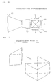
- FIG. 16 shows a concept of the major portion of a projection-type display apparatus.
- the projection-type display apparatus includes three liquid-crystal light valves 42, 44 and 46, a cross-dichroic prism 48 and a projection lens system 50.
- the cross-dichroic prism 48 synthesises three colour light beams of red, green and blue respectively modulated by the three light valves 42, 44 and 46 and outputs the synthesised light beam to the projection lens system 50.
- the projection lens system 50 projects the synthesised light beam onto a projection screen 52.
- FIG. 17 is a partly exploded perspective view showing the cross-dichroic prism 48.
- the cross-dichroic prism 48 is manufactured by gluing four right-angle prisms with right-angle surfaces interfaced by means of an optical adhesive.
- FIG. 18 is an explanatory view illustrating the problem that arises when the cross-dichroic prism 48 is used.
- the cross-dichroic prism 48 has a red-colour light reflecting film 60R and a blue-colour light reflecting film 60B, both of which are arranged in the shapes of the letter X at the interfaces formed in the right-angle surfaces of the four right-angle prisms. Since an optical adhesive layer 62 is formed in the gaps between four right-angle prisms, both the reflecting films 60R and 60B have a gap at the central axis 48a of the cross-dichroic prism 48.
- FIG. 18(B) shows one example of such a dark line DL.
- the dark line DL of a colour different from the rest of the image, presents a slightly darker band at the centre of the projected image. It is considered that the dark line DL is attributed to light scattering taking place in the gap in the central axis 48a and failure in the reflection of red-colour light and blue-colour light.
- This problem is also encountered in a cross-dichroic mirror in which two types of dichroic mirrors having selectively reflecting films, such as a red-colour light reflecting film and a blue-colour light reflecting film, are crossed in the letter X configuration. In this case, a dark line attributed to a central axis of the mirrors is also formed in a resulting image.
- the dark line is created at the centre of the screen by the central axis of the cross-dichroic prism 48 or the cross-dichroic mirror in the conventional projection-type display apparatus.
- This invention has been developed with a view to resolving the above problem, and it is an object of the present invention to provide a technique that makes less pronounced a dark line attributed to a central axis of optical means having dichroic films of two types arranged in the letter X configuration, such as a cross-dichroic prism and a cross-dichroic mirror.
- a z direction is aligned with the direction of travel of the light beam
- an x direction is at 9 o'clock position about the direction of travel of the light beam (z axis)
- a y direction is at 12 o'clock position.
- the x direction represents the direction of rows
- the y direction represents the direction of columns.
- illumination optical system also referred to as an integrator optical system
- two lens arrays each having a plurality of small lenses, as described in WO94/22042
- WO94/22042 are known as a technique for reducing nonuniform illuminance of an illuminating light by splitting a light beam into a plurality of partial light beams.
- FIG. 1 illustrates the principle of dark line generation in the projection-type display apparatus using a cross-dichroic prism which employs an integrator optical system.
- FIGS. 1(A-1) and 1(B-1) show light beams (represented by full lines) that are transmitted through small lenses 10 which are arranged in mutually different positions in the x direction, namely, small lenses 10 which are arranged in different positions in the direction of columns, and also show the trajectories (represented by thin broken lines) of central optical axes of the light beams, and FIGS. 1(A-2) and 1(B-2) show the positions of dark lines DLa and DLb on a screen 7.
- the light beam emitted by a light source is split into a plurality of partial beams through a first lens array 1 and a second lens array 2, each having a plurality of small lenses 10.
- the light beams transmitted through the small lenses 10 in the first and second lens arrays 1 and 2 are converted into parallel light beams in parallel with the central axis of a collimator lens 15.
- Partial light beams transmitted through the collimator lens 15 are superimposed on a liquid-crystal light valve 3 to illuminate uniformly a predetermined area.
- FIG. 1 shows a single liquid-crystal light valve 3 only, the same principle of the integrator optical system and generation of dark line are true of the other two liquid-crystal light valves in a system such as illustrated in Fig. 18(A).
- FIG. 2 is a perspective view showing the external appearance of the first and second lens arrays 1, 2.
- FIG. 1(A-1) shows a partial light beam transmitted through a small lens 10 in the second column
- FIG. 1(B-1) shows a partial light beam transmitted through a small lens 10 in the seventh column.
- Light beams superimposed on the liquid-crystal light valve 3 are modulated according to image information, and then directed to the cross-dichroic prism 4.
- the light beam output from the cross-dichroic prism 4 is projected onto the screen 7 through a projection lens system 6.
- a light beam passing through the portion of the central axis 5 (along the y direction) is also projected at the positions of Pa and Pb on the screen 7 as represented by heavy broken lines in FIGS. 1(A-1) and 1(B-1).
- light scattering takes place or a light, which would be otherwise reflected, is not reflected, in the gap between the reflecting films in the vicinity of the central axis 5, and the quantity of light passing through in and around the central axis 5 is reduced.
- FIGS. 1(A-2) and 1(B-2) an area suffering luminance lower than that of the surrounding area, namely the dark lines DLa and DLb are created.
- FIG. 3(A) is an enlarged fragmentary view of FIG. 1(A-1)
- an image formed through the liquid-crystal light valve 3 is inverted, enlarged and projected onto the projection screen 7 through the projection lens system 6.
- FIG. 3(B) is a cross-sectional view of the cross-dichroic prism 4 taken along the xy plane including the central axis 5.
- r1 represents the distance from one edge 11 of the cross section 8 of a partial light beam to the central axis 5 and r2 represents the distance from the other edge 12 of the cross section 8 of the partial light beam to the central axis 5, when the partial light beam is sectioned along the xy plane including the central axis 5 of the cross-dichroic prism 4.
- the ratio of the distance R2 from one edge 13 of a projection area 9 to the dark line DLa to the distance R1 from the other edge of the projection area 9 to the dark line DLa on the projection screen 7 is equal to the ratio of the distance r2 to the distance r1.
- the position of the dark line DLa depends on where the cross section 8 of the partial light beam in the xy plane including the central axis 5 of the cross-dichroic prism 4 is present relative to the central axis 5.
- FIG. 1(A-1) As understood from the comparison between FIG. 1(A-1) and FIG. 1(B-1), the position of the cross section of the partial light beam along the xy plane including the central axis 5 of the cross-dichroic prism 4 becomes different from FIG. 1(A-1) to FIG. 1(B-1).
- the dark lines DLa and DLb are therefore created at different positions.
- the position of the cross section of the light beam along the xy planes including the central axis 5 of the cross-dichroic prism 4 is different from column to column, and the number of the dark lines is equal to the number of columns of the first and second lens arrays 1 and 2, namely, N dark lines are created.
- Each of the N dark lines is created by the superimposed partial light beams that are transmitted through the M small lenses 10 arranged in the same columns in the first and second lens array 1 and 2, and darkness of the dark lines is equal to the sum of darkness of all dark lines created by the each of M small lenses 10.
- the position of the dark line created also differs.
- the light beams that are transmitted through different small lenses which positions in the direction of rows are different, are mutually different in position relative to the position of the central axis 5 of the cross-dichroic prism 4, and create dark lines in different positions.
- the reason why the position of the cross section of the partial light beam along the xy plane including the central axis 5 of the cross-dichroic prism 4 is different is that the angle of incidence of the partial light beam to the cross-dichroic prism 4 is different (see FIG. 1). Since the light beams that are transmitted through different small lenses which positions in the direction of rows are different enter the cross-dichroic prism 4 at different angles, the positions of the partial light beams relative to the central axis 5 are different.
- the overall darkness is substantially equal to the sum of darkness of all M small lenses 10. It is therefore preferred that the dark lines formed through the M small lenses 10 be created at different positions on the projection screen 7. With such an arrangement, darkness per dark line is lowered while the number of dark lines increases, and the dark lines are thus made less noticeable as a result. It is not required, however, that all dark lines from the M small lenses 10 are created in different positions, and it will be sufficient enough if some of dark lines are created in different positions.
- some of partial light beams transmitted through the M small lenses 10 arranged in the same column are changed in the positions of their central axes with respect to the central axis 5 of the cross-dichroic prism 4 relative to the remaining partial light beams.
- some of partial light beams that are transmitted through the M small lenses 10 arranged in the same column are changed in angle to the liquid-crystal light valve 3 or in angle to the cross-dichroic prism 4 relative to the remaining partial light beams.
- the present invention successfully resolves the above-described problem encountered in the conventional art by taking advantage of the above principles.
- the means, operation and advantages of the present invention are now discussed.
- an illumination optical system for emitting an illuminating light beam comprises:
- the "direction of rows” means a direction perpendicular to the direction of the central axis of the colour synthesising means.
- the direction of columns is therefore in parallel with the central axis.
- Each of three light modulation means correspond to an area of illumination.
- out of the plurality of partial light beams split through the first and second lens arrays at least one column of partial light beams of the plurality of partial light beams arranged in the direction of columns are transmitted at an approximately identical predetermined angle through the area of illumination, and project to the central axis of the colour synthesising means at substantially the same position on the screen to form a dark line.
- one of the groups is arranged to be offset from another group in the direction of rows in the first and second lens arrays, and partial light beams transmitted through the one area, are transmitted through the area of illumination, at a angle different from that at which the partial light beams transmitted through the other area are transmitted, and are transmitted through the cross-dichroic prism at a different position.
- the central axis of the colour synthesising means is prevented from being projected at the same position by light beams arranged in the direction of columns. As a result, the dark line created in the image projected is made less visible.
- an illumination optical system for emitting an illuminating light beam comprising:
- the optical means is preferably decentreed lenses that have an optical centre that is offset in the direction opposite to the direction in which the optical centre of the first small lenses is offset from the geometric centre of the first small lens.
- partial light beams, transmitted through the plurality of first and second small lenses are transmitted through the area of illumination at an angle different from that at which partial light beams transmitted through the remaining rows of small lenses are transmitted through the area of illumination, and are transmitted through the cross-dichroic prism at a different position.
- the central axis of the colour synthesising means is prevented from being projected at the same position by the partial light beams arranged in the direction of columns. As a result, the dark line created in the image projected is made less visible.
- At least one row of small lenses in the second lens array transmit partial light beams having a relatively large light quantity, are positioned to be offset from the remaining rows of small lenses in the second lens array in the direction of rows.
- the dark line created in the projected image is more pronounced if the angles at which partial light beams are transmitted through the area of illumination are equal. Since the angles at which the partial light beams having a relatively large light quantity are transmitted through the area of illumination are mutually different, the dark line created in the projected image is made less pronounced.
- the small lenses in odd-numbered rows and the small lenses in even-numbered rows are mutually and alternately offset in the direction of the rows.
- the angle at which the partial light beams transmitted through the odd rows of the first and second lens arrays are transmitted through the area of illumination is different from the angle at which the partial light beams transmitted through the even rows are transmitted through the area of illumination.
- the central axis of the colour synthesising means is prevented from being projected at the same position by the partial light beams arranged in the direction of columns. As a result, the dark line created in the image projected is made less visible.
- the second lens array is preferably divided into a plurality of areas by at least one division line and at least one of the plurality of areas is positioned to be offset from the remaining areas in the direction of rows.
- the angle at which the partial light beams transmitted through the one area of the second lens array are transmitted through the area of illumination is different from the angle at which the partial light beams transmitted through another area are transmitted through the area of illumination, and the central axis of the colour synthesising means is prevented from being projected at the same position by the partial light beams arranged in the direction of columns.
- the dark line created in the image projected is made less visible.
- the plurality of second small lenses in the second lens array are divided into a plurality of groups of rows,
- the dividing of the small lenses into the plurality of groups is performed such that the sums of quality of light of partial light beams that are respectively transmitted through the respective groups are substantially equal.
- the dark lines corresponding to the central axis of the colour synthesising means formed by the partial light beams transmitted through the respective groups are also different in darkness level.
- the object of the present invention is to make the dark line less visible, a difference in darkness of the dark lines is not preferable from the standpoint of making the dark line less visible, because light discrimination capability through comparison of relative strength is high. If the sums of light quantities of the partial light beams in the respective groups are equal to each other, the dark lines of the partial light beams in the respective groups are equalised in darkness level.
- the predetermined displacement of the groups of small lenses of about 1/2 to 2/3 of the width of one of the small lens in the direction of rows.
- the illumination optical system may comprise:
- the polarisation converting device is divided into a plurality of areas corresponding to the arrangement of the groups of small lenses of the first and second lens arrays.
- the polarisation converting device is divided into a plurality of areas corresponding to the arrangement of the optical means of the second lens array.
- the first group of rows of small lenses is offset from the second group of rows of small lenses by a displacement of about 1/4 to 1/3 of the width of one of the small lens in the direction of rows.
- the light beam output from the second lens array is converted into a linearly polarised light beam exiting from the polarisation separating film of the polarisation conversion device and a linearly polarised light beam, offset in the direction of rows, exiting from the reflecting film.
- an interval between partial light beams in the direction of rows is half the interval without the polarisation conversion device.
- a projection-type image display apparatus comprises:
- the dark line created in the projected image is made less visible in the same manner as in the first and second aspect of the invention.
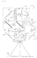
- FIG. 5 is a plan view showing diagrammatically a major portion of the projection-type display apparatus according to a first embodiment of the present invention.
- the direction of travel of light is the z direction
- the direction at 9 o'clock about the direction of travel of light (z direction) is the x direction
- the direction at 12 o'clock is the y direction.
- the projection-type display apparatus comprises an illumination optical system 100, dichroic mirrors 210 and 212, reflecting mirrors 218, 222, and 224, an entrance-side lens 230, a relay lens 232, three field lenses 240, 242, and 244, three liquid-crystal light valves (liquid-crystal panel) 250, 252 and 254, a cross-dichroic prism 260, and a projection lens system 270.
- the illumination optical system 100 comprises a light source 110, a first lens array 120, a second lens array 130, a polarisation conversion device 140, an superimposing lens 150, and a reflecting mirror 160.
- the illumination optical system 100 is an integrator optical system for illuminating uniformly the three liquid-crystal light valves 250, 252 and 254 as areas of illumination.
- the light source 110 comprises a light source lamp 112 as a radiation source for radially emitting light rays, and a concave mirror 114 for reflecting the light rays from the light source lamp 112 in a substantially parallel beam.
- the concave mirror 114 is preferably a praboloidal mirror.
- the first and second lens arrays 120 and 130 function as light beam splitting means.
- the first lens array 120 splits the light beam from the light source 110 into a plurality of partial beams while condensing each partial light beam at the same time.
- the second lens array 130 aligns the optical axes of the partial light beams substantially in parallel with the optical axis of the system.
- the polarisation conversion device 140 converts the incident light beam into a predetermined linearly polarised light beam.
- the superimposing lens 150 superimposes a plurality of partial light beams having central axes in parallel with the system optical axis on predetermined areas of illumination (namely, the liquid-crystal light valves 250, 252 and 254).
- the field lenses 240, 242 and 244 convert the partial light beams for illuminating areas of illumination into respective light beams in parallel with respective central axes of the areas.
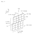
- FIG. 6 is a perspective view showing the external appearance of the first lens array 120.
- the first lens array 120 has a generally rectangular matrix of M rows and N columns of small lenses 122 arranged two-dimensionally.
- the x direction corresponds to the direction of the rows of lens array and the y direction corresponds to the direction of columns.
- the small lenses from a first row to a third row (first group of rows) and the small lenses from a fourth row to a sixth row (second group of rows) are offset in the directions of -x and +x, respectively from a centre line Ly extended in the y direction.
- Such a lens array may be manufactured by assembling two lens arrays with a displacement allowed therebetween, but more typically, the lens array is manufactured using a one-piece molding technique. The displacement will be detailed further later.
- the second lens array 130 has a matrix of M rows and N columns of small lenses respectively corresponding to the small lenses 122 in the first lens array 120.
- Each small lens 122 splits the light beam emitted from the light source 110 (FIG. 5) into a plurality of partial light beams (namely, M x N partial light beams) and focuses each partial light beam in the vicinity of the second lens array 130.
- the external appearance of each small lens 122 viewed from the z direction, is set to substantially correspond to the shape of the liquid-crystal light valves 250, 252 and 254.
- the aspect ratio (width-to-height proportions) of the small lens 122 is set to be 4:3 but may be set to another value.
- the second lens array 130 aligns the optical axes of the partial light beams in parallel with the optical axis of the system. If the light beam emitted from the light source 110 is a parallel beam in parallel with the system optical axis, the central axes of the partial light beams exiting from the small lenses 122 of the first lens array 120 are also in parallel with the system optical axis, and the second lens array 130 may be dispensed with in such a case. If the light source 110 emits a light beam having a central axis inclined at an angle with respect to the system optical axis, the central axes of the partial light beams exiting from the small lenses 122 are not in parallel with the system optical axis.
- Partial light beams having a central axis angled with respect to the system optical axis may fail to illuminate the originally intended, predetermined areas of illumination, namely the liquid-crystal light valves 250, 252 and 254. This lowers utilisation of light in the projection-type display apparatus.
- the partial light beams having central axes inclined at an angle with respect to the system optical axis are introduced into small lenses 132 of the second lens array 130, the second lens array 130 converts the central axes of the partial light beams to be in parallel with the system optical axis thereby resulting in improved utilisation of light.
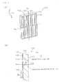
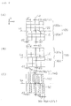
- FIG. 7 is an explanatory view showing the construction of the polarisation conversion device 140 (FIG. 5).
- the polarisation conversion device 140 comprises a polarising beam splitter array 141 and a selective phase plate 142.
- a polarisation conversion device corresponding to the small lens from top to the third row and a polarisation conversion device corresponding to the small lenses from the fourth row to the sixth row in the first and second lens arrays 120 and 130 as shown in FIG. 6, are offset in the directions of -x and +x, respectively, from a centre line Sy extended in the y direction.
- the displacement of the polarisation conversion device will be detailed further later.
- the polarising beam splitter array 141 may be constructed by gluing a plurality of transparent plates 143, each having a parallelogram shape in cross section. The interfaces between the transparent plates 143 alternate between a polarisation separating film 144 and reflecting film 145.
- the polarising beam splitter array 141 is manufactured by gluing a plurality of glass plates with the polarisation separating film 144 and the reflecting film 145 alternately interposed therebetween, and by cutting them at a predetermined inclined angle.
- Light beams transmitted through the first and second lens arrays 120 and 130 are introduced into the polarisation conversion device 140, and then separated into an s-polarised light beam and a p-polarised light beam through the polarisation separating film 144 as shown in FIG. 7(B).
- the p-polarised light beam is transmitted through the polarisation separating film 144.
- the s-polarised light beam is reflected by the polarisation separating film 144 is again reflected by the reflecting film 145, and exits in parallel with the p-polarised light beam which is directly transmitted through the polarisation separating film 144.
- the selective phase plate 142 is an optical element that has a ⁇ /2 phase layer 146 on its light exit surface where the light beam transmitted through the polarisation separating film 144 passes, while having no ⁇ /2 phase layer 146 on its light exit surface where the light beam reflected by the reflecting film 145 passes.
- the p-polarised light beam transmitted through the polarisation separating film 144, before exiting, is converted into an s-polarised light beam through the ⁇ /2 phase layer 146.
- randomly polarised light beams incident on the polarisation conversion device 140 are entirely converted into the s-polarised light beams before exiting.
- the incident light beams may be converted into the p-polarised light beams by forming the ⁇ /2 phase layer 146 in the selective phase plate 142 on the light exit portion where the light beam reflected from the reflecting film 145 passes.
- the parallel light beam emitted from the light source 110 is split into the plurality of partial light beams through the first and second lens arrays 120 and 130, constituting the integrator optical system.
- each small lens 122 in the first lens array 120 condenses the partial light beam exiting therefrom to form the image of the light source 110 (a secondary light source image) in the vicinity of the polarisation separating film 144 of the polarisation conversion device 140.
- the partial light beams incident on the polarisation conversion device 140 are converted into two types of polarised light beams through the polarisation separating film 144 and reflecting film 145.
- the secondary light source image is formed on the reflecting film 145 as well as on the polarising separating film 144. More particularly, in the polarisation conversion device 140, the secondary light source images which number is two times as many as that of partial light beams transmitted through the first and second lens arrays 120 and 130, are created.
- the superimposing lens 150 superimposes the partial light beams exiting from the secondary light source images formed in the polarisation conversion device 140 to condense them on the liquid-crystal light valves 250, 252 and 254.
- the reflecting mirror 160 reflects the light beam exiting from the superimposing lens 150 toward the dichroic mirrors 210, but is not necessarily required depending on the construction of the apparatus.
- the liquid-crystal light valves 250, 252 and 254 are uniformly illuminated by generally one type of polarised light beams (s-polarised light beams in this embodiment).
- the dichroic mirrors 210, 212 separate the white light beam condensed by the superimposing lens 150 into three colour light beams of red, green and blue.
- the first dichroic mirror 210 allows to be transmitted therethrough the red colour component of the white light beam emitted from the illumination optical system 100 while reflecting the blue colour component and green colour component of the white light beam.
- the red colour light beam transmitted through the first dichroic mirror 210 is reflected by a reflecting mirror 218, passes through a field lens 240 and reaches the red-colour liquid-crystal light valve 250.
- the field lens 240 converts the partial light beams exiting from the second lens array 130 into a parallel light beam in parallel with its central axis.
- the fields lenses 242 and 244 arranged in front of the respective liquid-crystal light valves work in a similar way.
- the green-colour light beam, out of the green-colour and blue-colour light beams reflected from the first dichroic mirror 210, is reflected by the second dichroic mirror 212, passes through the field lens 242, and reaches the green-colour liquid-crystal light valve 252.
- the blue-colour light beam is transmitted through the second dichroic mirror 212, is guided through a relay lens system including entrance-side lens 230, a relay lens 232, and reflecting mirrors 222 and 224, further pass through the exit-side lens (field lens) 244, and reaches the blue-colour liquid-crystal light valve 254.
- the relay lens system is used for the blue-colour light beam to prevent a drop in utilisation of light, because the length of the optical path for the blue-colour light beam is longer than those of other colour light beams. More particularly, the relay lens system is used to transmit the partial light beam incident on the entrance-side lens 230, as it is, to the exit-side lens 244.
- the three liquid-crystal light valves 250, 252 and 254 form an image by modulating the three colour light beams based on given information (image signal).
- the cross-dichroic prism 260 synthesises the three colour light beams to form a colour image.
- the construction of the cross-dichroic prism 260 may be identical to that described with reference to FIGS. 17 and 18. More particularly, the cross-dichroic prism 260 includes a multi-layered dielectric film for reflecting a red-colour beam and a multi-layered dielectric film for reflecting a blue-colour light beam, arranged in the letter X configuration at the interfaces between four right-angle prisms.
- These multi-layered dielectric films synthesise three colour light beams resulting in a synthesised light beam as a colour image to be projected.
- the synthesised light beam produced by the cross-dichroic prism 260 is output toward the projection lens system 270.
- the projection lens system 270 projects the synthesised light beam onto a projection screen 300 to present a colour image on screen.
- FIG. 8 is a front view of the first lens array 120, second lens array 130 and polarisation conversion device 140, viewed from the z direction.
- the position of the first lens array 120 shown in FIG. 8(A) and the position of the second lens array 130 shown in FIG. 8(B) are based on the y-direction extending centre line Ly including the optical axis LC of the light source.
- the position of the polarisation conversion device 140 shown in FIG. 8(C) is based on the y-direction extending centre line Sy including the system optical axis SC.
- centre lines Ly and Sy There is a displacement of distance d4 in the x direction between both centre lines Ly and Sy.
- x-direction extending centre lines Lx and Sx are separately shown for the first lens array 120, second lens array 130 and polarisation conversion device 140 in their respective front views, they are actually aligned at the same position in the y direction. More particularly, the light source optical axis LC and the system optical axis SC are at the same position in the y direction but at different positions in the x direction.
- the centre line Ly is identical to the y-direction extending centre lines of the first lens array 120 and second lens array 130.
- the centre line Ly is identical to the y-direction extending centre line of the polarisation conversion device 140.
- upper portions 120u from a top row to the third row
- lower portions 120d from the fourth row to the sixth row
- the relative displacement d2 between the upper portions 120u and the lower portions 120d is therefore twice the displacement d3 with respect to the centre line Ly.
- the polarisation conversion device 140 also has a displacement with its upper portion and lower portion shifted from the centre line Sy in the directions of -x and +x, respectively.
- the y-direction extending centre line Sy of the polarisation conversion device 140 is offset from the centre line Ly of the first lens array 120 and second lens array 130 by the displacement d4 in the direction of -x.
- the displacement d4 is approximately equal to Wp/2, namely half the width Wp of the polarisation separating film 144 of the polarisation conversion device 140 in the x direction (note that the width of the reflecting film 145 in the x direction is equal to the width of the polarisation separating film 144 in the x direction).
- half the light beam incident on the polarisation conversion device 140 passes therethrough, and the remaining half the light beam, before being output, is shifted by the width Wp of the film in the direction of -x.
- the central axis of the two light beams are thus shifted by Wp/2 in the direction of -x from the centre of the light beam entering the polarisation conversion device 140.
- the displacement d4 between the y-direction extending centre line Sy of the polarisation conversion device 140 and the y-direction extending centre line Ly of the first lens array 120 and second lens array 130 thus corresponds to the displacement between the incident light beam and the exit light beams in the polarisation conversion device 140.
- the centres of the small lenses in the first lens array 120 and second lens array 130 are generally aligned with the centres of the polarisation separating film 144 in the x direction. Since each partial light beam passing through the respective small lens is directed to approximately the centre of the polarisation separating film 144, the partial light beams passing through the first lens array 120 and second lens array 130 are efficiently utilised.
- FIG. 9 is an explanatory view illustrating the function of the first lens array 120, second lens array 130 and polarisation conversion device 140 in the first embodiment.
- FIG. 9(A) shows the optical path of a light beam passing through a small lens at the third row from top
- FIG. 9(B) shows the optical path of a light beam passing through a small lens at the fourth row from top.
- the optical paths of light beams passing through small lenses at the first and second rows from top are similar to the one for the light beam passing through the third-row small lens shown in FIG. 9(A).
- the optical paths of light beams passing through small lenses at the fifth and sixth rows from top are similar to the one for the light beam passing through the fourth-row small lens shown in FIG. 9(B).
- FIG. 9 shows only the major portion of the optical paths from the light source 110 to the liquid-crystal light valve 252.
- FIG. 9 shows the optical paths of the light beams passing through the second-column small lenses in the first lens array 120 and second lens array 130.
- a partial light beam L32 split by the small lens 122 at the third row in the first lens array 120 is condensed on the polarisation separating film 144 in the polarisation conversion device 140.
- a partial light beam L32a out of the light beam L32 is directly transmitted through the polarisation separating film 144 and illuminates an area of illumination 252a of the liquid-crystal light valve 252 through the light condensing effect of the superimposing lens 150.
- a partial light beam L32b which is reflected by the polarisation separating film 144 and further by the reflecting film 145, also illuminates the area of illumination 252a.
- the two partial light beams L32a and L32b are transmitted through the centre of the area of illumination 252a with their respective central axes 32acl and 32bcl angled at respective angles of incidence ⁇ 32a and ⁇ 32b to the area of illumination 252a.
- a partial light beam L42 split by the small lens 122 at the fourth row in the first lens array 120 is condensed on the polarisation separating film 144 in the polarisation conversion device 140.
- a partial light beam L42a out of the condensed light beam L42 is directly transmitted through the polarisation separating film 144 and illuminates an area of illumination 252a of the liquid-crystal light valve 252 through the light condensing effect of the superimposing lens 150.
- a partial light beam L42b which is reflected by the polarisation separating film 144 and further by the reflecting film 145, also illuminates the area of illumination 252a.
- the two partial light beams L42a and L42b are transmitted through the centre of the area of illumination 252a with their respective central axes 42acl and 42bcl angled at respective angles of incidence ⁇ 42a and ⁇ 42b to the area of illumination 252a.
- the partial light beam L32 (later split into L32a and L32b) and the partial light beam L42 (later split into L42a and L42b) arrive at the superimposing lens 150 at different entrance positions in the x direction.
- the angles of incidence 0 32 ( ⁇ 32a and ⁇ 32b) of the partial light beam L32 incident on the area of illumination 252a and the angles of incidence ⁇ 42 ( ⁇ 42a and ⁇ 42b) of the partial light beam L42 incident on the area of illumination 252a are different from each other.
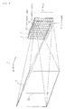
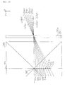
- FIG. 10 is an explanatory view showing how the partial light beams transmitted through the third row and fourth row in the first lens array 120 and second lens array 130 are transmitted through the cross-dichroic prism 260.
- the full lines shown represent central axes L31bcl and L31acl of the partial light beams transmitted through a small lens in the third row and the first column and central axes L32bcl and L32acl of the partial light beams transmitted through a small lens in the third row and the second column.
- the broken lines shown represent central axes L41bcl and L41acl of the partial light beams transmitted through a small lens in the fourth row and the first column and central axes L42bcl and L42acl of the partial light beams transmitted through a small lens in the fourth row and the second column.
- the central axes L31bcl, L31acl, L32bcl and L32acl of the partial light beams transmitted through small lenses in the third row and first and second columns pass the centre of the area of illumination 252a, enter the cross-dichroic prism 260, and pass at different points 31b, 31a, 32b and 32a on a central plane 264 which the central axis 262 of the cross-dichroic prism 260 lies in and which is in parallel with the liquid-crystal light valve 252.
- the dark lines that are caused by the partial light beams transmitted through the small lens in the third row and the first and second columns have a pitch generally proportional to the distance between each passing point and the central axis 262.
- the central axes L41bcl, L41acl, L42bcl and L42acl of the partial light beams transmitted through small lenses in the fourth row and first and second columns pass the centre of the area of illumination 252a, enter the cross-dichroic prism 260, and pass at different points 41b, 41a, 42b and 42a on the central plane 264. Since as already described with reference to FIG.
- the angle of incidence to the area of illumination 252a, of the central axis of each partial light beam transmitted through the small lens at the fourth row is different from the angle of incidence of the central axis of each partial light beam transmitted through the small lens at the third row, the points 41b, 41a, 42b and 42a are placed in the middle between the points 31b, 31a, 32b and 32a, respectively.
- the dark lines caused by the partial light beams transmitted through the small lenses in the fourth row and the first column and second column appear in the middle between the partial light beams at the third row.
- the dark lines formed by the M partial light beams split in the same column are not concentrated at one position and are thus made less visible.
- the dark lines arising from the M partial light beams in the same column are presented in two positions correspondingly to the upper and lower portions of the first lens array 120 and second lens array 130.
- Each of the M partial light beams in the same column is originally separated into one beam by the polarisation separating film 144 and the one by the reflecting film 145 in the polarisation conversion device 140, and create two dark lines.
- the "two positions corresponding to the upper and lower portions" means therefore that each of the two dark lines is further separated into two dark lines.
- the intervals between the dark lines are proportional to the intervals between each of the points 31b, 32a, 32b, 32a,... and 41b, 41a, 42b, 42a,... and the central axis 262 on the central plane 264.
- the dark lines arising from the partial light beams are not superimposed and that the points 41b, 41a, 42b, 42a,... are mutually interposed in the middle between the points 31b, 32a, 32b, 32a,..., respectively.
- the interval between the dark lines is preferably set to be as wide as possible, and the points 41b, 41a, 42b, 42a,...
- the displacement d2 between the first lens array 120 and the second lens array 130 shown in FIG. 8 is preferably 1/4 of width dl of the small lens 122 in the x direction.
- the points 41b, 41a, 42b, 42a,... are mutually interposed in the middle between the points 31b, 32a, 32b, 32a,..., respectively.
- the present invention may be implemented in a display apparatus without the polarisation conversion device 140.
- This arrangement is equivalent to the state of the first embodiment in which the partial light beams arising from the reflecting film 145 in the polarisation conversion device 140 are not present, and it is sufficient enough if the displacement d2 between the first lens array 120 and the second lens array 130 shown in FIG. 8 is set to be 1/2 of the width d1 of the small lens 122 in the x direction.
- the polarisation conversion device 140 is dispensed with, it is not necessary to separate the second lens array 130 and the superimposing lens 150 and a lens array having the functions of the first lens array 120 and superimposing lens 150 (FIG.
- the small lenses in rows of the first lens array 120 and the second lens array 130 are divided into two groups and the small lenses in the first group is offset from the small lenses in the second group.
- the small lenses may divide into three groups every two rows so that one group of rows is arranged to be offset from adjoining groups.
- the first and second lens array is divided into a plurality groups of rows, each of the groups includes at least two rows of small lenses and is offset from adjoining groups.
- FIG. 11 is a front view of a first lens array 120A, a second lens array 130A and a polarisation conversion device 140A in a second embodiment, viewed from the z direction.
- the second lens array 130A has an upper portion 130Au (from the top row to the third row) and a lower portion 130Ad (from the fourth row to the sixth row) offset respectively in the directions of -x and +x by a displacement d3A with respect to the centre line Ly.
- the relative displacement d2A between the upper portion 130Au and the lower portion 130Ad is twice as large as the displacement (offset) d3A relative to the centre line Ly.
- the polarisation conversion device 140A also includes the displacement (offset) d3A in its structure with respect to the centre line Sy in the directions of -x and +x to correspond to the displacement between the upper portion 130Au and the lower portion 130Ad in the second lens array 130.
- the centre line Sy is offset from the centre line Ly in the direction of -x by a displacement d4A approximately equal to half the x-direction width Wp of the polarisation separating film 144 or the reflecting film 145 in the polarisation conversion device 140A so that the centre of each small lens is generally aligned with the centre of the respective polarisation separating film 144 of the polarisation conversion device 140A in the x direction. Since the components and basic functions of the polarisation conversion device 140 remain unchanged from those of the polarisation conversion device 140 shown in FIG. 7, no further discussion about them is provided.
- Small lenses 120A, 130A in the first and second lens arrays 120, 130 of this second embodiment are different from the small lenses 122 in the first and second lens arrays 120, 130 of the first embodiment.
- the small lens 122 in the first embodiment has its lens optical axis (optical centre) aligned with its lens centre (geometric centre).
- the small lens constituting the first and second lens arrays 120A, 130A in the second embodiment is a decentreed lens in which its lens optical axis is not aligned with the lens centre. Referring to FIG. 11, a full line cross drawn in each small lens represents the optical axis of each small lens.
- each small lens 122Aa in the upper portion 120Au (from the top row to the third row) in the first lens array 120A is offset by a displacement d3A from the lens centre of the small lens in the direction of -x
- the optical axis of the corresponding small lens 132Aa in the upper portion 130Au in the second lens array 130A is shifted by a displacement d3A from its lens centre in the direction of +x.
- each small lens 122Ab in the lower portion 120Ad (from the fourth row to the sixth row) in the first lens array 120A is offset by a displacement d3A from the lens centre of the small lens in the direction of +x
- the optical axis of the corresponding small lens 132Ab in the lower portion 130Ad in the second lens array 130A is shifted by a displacement d3A from its lens centre in the direction of -x.
- FIG. 11(D) shows examples of the structure of small lenses (decentreed lenses) with their optical axes shifted as described above.
- small lenses 122Aa (132Ab) and 132Aa (122Ab) are decentreed lenses which are manufactured by cutting a spherical lens in a predetermined shape so that its optical axis is shifted (offset) from its centre. More typically, the entire lens array is formed using a one-piece molding technique.
- the displacement between the optical axis and the lens centre in each of the lenses 122Aa, 122Ab, 132Aa and 132Ab is equal to the displacement d3A of the upper and lower portions with respect to the centre line Ly.
- FIG. 12 is an explanatory enlarged view showing small lenses of the first and second lens arrays 120A and 130A.
- FIG. 12(A) shows small lenses in the upper portion viewed from the y direction and
- FIG. 12(B) shows small lenses in the lower portion viewed from the y direction. As shown in FIG.
- both the small lens 122Aa in the upper portion in the first lens array 120A and the corresponding small lens 132Aa in the second lens array 130A are arranged such that the lens centre 122a(GC) of the small lens 122Aa is aligned with the optical axis 132a(OC) of the small lens 132Aa while the optical axis 122a(OC) of the small lens 122Aa is aligned with the lens centre 132a(GC) of the small lens 132Aa at the same time.
- FIG. 12(A) both the small lens 122Aa in the upper portion in the first lens array 120A and the corresponding small lens 132Aa in the second lens array 130A are arranged such that the lens centre 122a(GC) of the small lens 122Aa is aligned with the optical axis 132a(OC) of the small lens 132Aa while the optical axis 122a(OC) of the small lens 122Aa is aligned with the lens centre 132a(GC) of
- both the small lens 122Ab in the lower portion in the first lens array 120A and the corresponding small lens 132Ab in the second lens array 130A are arranged such that the lens centre 122b(GC) of the small lens 122Ab is aligned with the optical axis 132b(OC) of the small lens 132Ab while the optical axis 122b(OC) of the small lens 122Ab is aligned with the lens centre 132b(GC) of the small lens 132Ab at the same time.
- the central axis of a partial light beam L1 incident on the small lens 122Aa is deflected by the small lens 122Aa so that it passes through the centre of the corresponding small lens 132Aa.
- the deflected partial light beam L1 After passing through the small lens 132Aa, the deflected partial light beam L1 is deflected back again such that it becomes parallel with its direction of travel prior to incidence on the small lens 122Aa.
- the optical path of the partial light beam L1 is shifted in parallel by the displacement d3A in the direction of -x with respect to its path prior to incidence on the small lens 122Aa.
- a partial light beam L2 incident on the small lens 122b is shifted in parallel by the displacement d3A with respect to its path prior to incidence on the small lens 122Ab through the deflection functions by the small lenses 122b and 132b.
- the optical paths of the partial light beams passing the same column in the upper portion and lower portion of the first and second lens arrays 120A, 130A are therefore subject to a relative displacement equal to twice the displacement d3A.
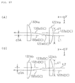
- FIG. 13 is an explanatory view illustrating the function of the first and second lens arrays 120A, 130A and polarisation conversion device 140A in the second embodiment.
- FIG. 13(A) shows two partial light beams L32Aa and L32Ab passing through the third row and the second column in the first and second lens arrays 120A and 130A.
- Two partial light beams L32Aa and L32Ab are transmitted through the centre of the area of illumination 252a with their respective central axes 32Aacl and 32Abcl angled at respective angles of 032Aa and 032Ab to the area of illumination 252a.
- FIG. 13(B) shows two partial light beams L42Aa and L42Ab passing through the fourth row and the second column in the first and second lens arrays 120A and 130A.
- Two partial light beams L42Aa and L42Ab are transmitted through the centre of the area of illumination 252a with their respective central axes 42Aacl and 42Abcl angled at respective angles of 042Aa and 042Ab to the area of illumination 252a.
- the partial light beam L32A (including L32Aa and L32Ab) and the partial light beam L42A (including L42Aa and L42Ab) arrive at the superimposing lens 150 at different entrance positions in the x direction through the deflection functions of the small lenses 122Aa and 132Aa and 122Ab and 132Ab in the respective first and second lens arrays 120A and 130A as already described.
- the angles of incidence of the central axes of the partial light beams namely the angles of incidence ⁇ 32A ( ⁇ 32Aa and ⁇ 32Ab) of the partial light beam L32A and the angles of incidence ⁇ 42A ( ⁇ 42Aa and ⁇ 42Ab) of the partial light beam L42A are different to each other.
- ⁇ 32Ab ⁇ ⁇ 42Ab ⁇ ⁇ 32Aa ⁇ ⁇ 42Aa If the angles of incidence of the partial light beams are different, the positions of the dark lines formed by these partial light beams are also different.
- the dark lines formed by the M partial light beams split in the same column are not concentrated at one position and are thus made less visible.
- the dark lines arising from the M partial light beams in the same column are presented in two positions correspondingly to the upper and lower portions of the first lens array 120A and second lens array 130A.
- the displacement d2A between the upper portion and the lower portion of the second lens array 130A shown in FIG. 11 is preferably set to be 1/4 of the width d1A of the small lens 132A (132Aa, 132Ab) so that the dark lines generated by the columns in the lower portion are interposed in the middle of the respective intervals of the dark lines generated by the partial light beams of the upper portion.
- each dark line is formed in the middle of the interval between respective dark lines generated by the upper portion light beams.
- the present invention may be implemented in a display apparatus without the polarisation conversion device 140A as in the first embodiment.
- This arrangement is equivalent to the state of the second embodiment in which the partial light beams arising from the reflecting film 145 in the polarisation conversion device 140 are not present, and it is sufficient enough if the displacement d2 in the second lens array 130A shown in FIG. 11 is set to be 1/2 of the width d1A of the small lens 132A (132Aa and 132Ab) in the x direction.
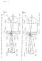
- FIG. 14 is a front view of a first lens array 120B, a second lens array 130B and a polarisation conversion device 140B in a third embodiment, viewed from the z direction.
- the third embodiment has odd-numbered rows and even-numbered rows in the second lens array 130B shifted respectively in the directions of -x and +x by a displacement d3B with respect to the centre line Ly.
- the displacement d2B of the even-numbered rows relative to the odd-numbered rows is equal to twice the displacement d3B with respect to the centre line Ly.
- each small lens 122Ba in the odd-numbered rows in the first lens array 120B is shifted by a displacement d3B from the lens centre of the small lens in the direction of -x
- the optical axis of the corresponding small lens 132Ba in the second lens array 130B is shifted by a displacement d3B from its lens centre in the direction of +x.
- the lens centre is aligned with the optical centre between both small lenses in the x direction.
- each small lens 122Bb in the even-numbered rows in the first lens array 120B is shifted by a displacement d3B from the lens centre of the small lens in the direction of +x as in the odd-numbered rows
- the optical axis of the corresponding small lens 132Bb in the second lens array 130B is shifted by a displacement d3B from its lens centre in the direction of -x.
- the lens centre is aligned with the optical centre between both small lenses in the x direction.
- the polarisation conversion device 140B also includes its odd-numbered rows and even-numbered rows shifted by a displacement d3A in its structure with respect to the centre line Sy in the directions of -x and +x, respectively, to correspond to the displacement in the second lens array 130B.
- the centre line Sy is shifted from the centre line Ly in the direction of -x by a displacement d4 approximately equal to half the x-direction width Wp of the polarisation separating film 144 or the reflecting film 145 in the polarisation conversion device 140 so that the centre of each small lens in the second lens array 130B is generally aligned with the centre of the respective polarisation separating film 144 in the x direction.
- the third embodiment relatively shifts, in the x direction, the partial light beams transmitted through the odd-numbered rows from the partial light beams transmitted through the even-numbered rows in the second lens array 120B. Since the dark lines formed by the partial light beams arranged in the same column are separated into ones arising from the partial light beams through the odd-numbered rows and ones arising from the partial light beams through the even-numbered rows, the dark lines are made less visible.
- the third embodiment has also the following advantage.
- the light source 110 presents the highest brightness in the vicinity of the optical axis of the light source lamp 112, while presenting gradually weakening brightness away from the optical axis.
- brightness is not necessarily spherically symmetrical with respect to the optical axis, left to right, and up to down. More particularly, in connection with brightness of the partial light beams passing through the first and second lens arrays 120B and 130B, brightness level at the second row and fifth row is now considered as a medium brightness as shown in FIG. 14(D), and the third and fourth rows are brighter and the first and sixth rows are darker. As shown in FIG.
- the first, third and fifth rows are combined into a first group
- the second, and fourth and sixth rows are combined into a second group so that the first and second groups may be shifted in position in the x direction.
- dark lines at a substantially equal darkness level are separately formed in two positions, and are thus less visible than dark lines having different darkness levels.
- the grouping is not limited to the grouping by odd-even numbers, but it is important that the light quantity of the partial light beams in each group be substantially equal from group to group.
- the number of groups may be three, rather than two. If the variation in light quantity along a vertical axis is symmetrical, this method may be applied to the second embodiment as well.
- the second and third embodiments are identical in that the dark lines generated by the partial light beams through in the same column are separated in two positions.
- the advantage of the second embodiment over the third embodiment is that the first and second lens arrays and polarisation conversion device are of a simple construction.
- the dark lines arising from the partial light beams are not superimposed and that the intervals between the dark lines are spaced as wide as possible.
- the displacement d2B between the odd-numbered rows and the even-numbered rows in the second lens array 130B shown in FIG. 14 is preferably set to be 1/4 of the width d1A of the small lens 132B (132Ba, 132Bb) so that the dark lines generated by the odd-numbered rows are interposed in the middle of the respective intervals of the dark lines generated by the partial light beams through the even-numbered rows in this embodiment.
- each dark line is formed in the middle of the interval between respective dark lines generated by the upper portion light beams.
- the present invention may be implemented in a display apparatus without the polarisation conversion device 140B as in the first and second embodiments.
- This arrangement is equivalent to the state of the third embodiment in which the partial light beams arising from the reflecting film 145 in the polarisation conversion device 140B are not present, and it is sufficient enough if the displacement d2B in the second lens array 130B shown in FIG. 14 is set to be 1/2 of the width d1B of the small lens 132B (132Ba and 132Bb) in the x direction.
- FIG. 15 is a front view of a first lens array 120C, a second lens array 130C and a polarisation conversion device 140C in a fourth embodiment, viewed from the z direction.
- the third row and fourth row in the second lens array 130C are shifted by a displacement d3C from the centre line Ly in the directions of +x and -x, respectively.
- the displacement d3C of the fourth row relative to the third row is equal to twice the displacement d3C with respect to the centre line Ly.
- each small lens 122Ca in the third row in the first lens array 120C is shifted by a displacement d3C from the lens centre of the small lens in the direction of +x
- the optical axis of the corresponding small lens 132Ca in the second lens array 130C is shifted by a displacement d3C from its lens centre in the direction of -x.
- the lens centre is aligned with the optical centre between both small lenses in the x direction.
- each small lens 122Cb in the fourth row in the first lens array 120C is shifted by a displacement d3C from the lens centre of the small lens in the direction of -x
- the optical axis of the corresponding small lens 132Cb in the second lens array 130C is shifted by a displacement d3C from its lens centre in the direction of +x.
- the lens centre is aligned with the optical centre between both small lenses.
- the small lenses in the remaining rows are condenser lenses with their lens centres respectively aligned with optical axes.
- the polarisation conversion device 140C also includes the third row and fourth row shifted with respect to the centre line Sy in the directions of -x and +x, respectively, to correspond to the displacement in the second lens array 130C.
- the centre line Sy is shifted from the centre line Ly in the direction of -x by a displacement d4C approximately equal to half the x-direction width Wp of the polarisation separating film 144 or the reflecting film 145 in the polarisation conversion device 140C so that the centre of each small lens in the second lens array 130C is generally aligned with the centre of the respective polarisation separating film 144 in the x direction.
- the fourth embodiment relatively shifts the partial light beams transmitted through the third row and the partial light beams transmitted through the fourth row in the second lens array 120C from the partial light beams transmitted through the remaining rows in the x direction. Since the dark lines generated by the partial light beams arranged in the same column are separated into three, namely one by the partial light beams through the third row, one by the partial light beams through the fourth row and the other by the partial light beams through the remaining rows, the dark lines are made less visible.
- the dark lines arising from the partial light beams in the vicinity of the light source optical axis are particularly noticeable.
- the dark lines arising from the partial light beams in the vicinity of the light source optical axis are prevented from being superimposed.
- the fourth embodiment is a particularly useful embodiment in such a case.
- the dark lines arising from the partial light beams are not superimposed and that the intervals between the dark lines are spaced as wide as possible.
- the dark lines generated by the partial light beams transmitted through the third and fourth rows in the same column are formed with displacements therebetween in the directions of ⁇ x with respect to the dark lines generated by the remaining partial light beams.
- the dark lines may be superimposed on the dark lines generated by the partial light beams through the third row and fourth row in a next column.
- the interval between the dark lines generated by the partial light beams by the rows except the third and fourth rows is preferably divided into three equal sub-intervals by the dark lines generated by the partial light beam in the third row and the partial light beam in the fourth row.
- the displacement d2C between the third row and the fourth row in the second lens array 130C shown in FIG. 15 is preferably set to be 1/3 of the width d1C of the small lens 132C (132Ca and 132Cb) in the x direction.
- the present invention may be implemented in a display apparatus without the polarisation conversion device 140C as in the first through third embodiments.
- This arrangement is equivalent to the state in which the partial light beams arising from the reflecting film 145 in the polarisation conversion device 140C are not present, and it is sufficient enough if the displacement d2C in the second lens array 130C shown in FIG. 15 is set to be 2/3 of the width d1C of the small lens 132C (132Ca and 132Cb) in the x direction.
- the present invention is not limited to the above embodiments including the second through fourth embodiments, and a variety of changes and modification are possible within the scope of the present invention, and the following modifications are possible, for example.
- the second lens array may have rows which are shifted in different positions from row to row or which are shifted in different positions from area to area in which the rows are divided into a plurality of areas along division lines running in the direction of rows. In the second lens array, one single row only or one single area only may be shifted into a different position in the direction of rows.
- the light beam from the light source is split into a matrix of a plurality of light beams in the above embodiments, the present invention is implemented when the light beam is split into a plurality of light beams at least in substantially one row.
- second small lenses in at least one row may be shifted in position by a predetermined displacement in the direction of rows from the small lenses in the other rows.
- the displaced second small lenses successfully receive the light beams exiting from the first lens array.
- first small lenses in the first lens array corresponding to the second small lenses may be of a decentreed lens in which its geometric centre is decentreed from its optical centre in the direction of rows.
- the partial light beams arranged in one column in the same direction of columns and exiting from the second lens array preferably illuminate the same position on the area of illumination regardless of the displacement of the small lenses in the direction of rows.
- the second small lenses are constructed of a decentreed lens which has its optical centre shifted in the direction opposite to the direction in which the optical centre is shifted from the geometric centre in the first small lens so that the polarised light beams incident on the second small lenses in the second lens array travel in the same direction as the partial light beams incident on the first small lenses in the first lens array.
- the superimposing lens arranged downstream of the second lens array superimposes the partial light beams in one column in the same direction of columns on the same area of illumination.
- the angles of incidence of the partial light beams, transmitted through the first and second lens arrays, to the area of illumination are different from the angles of incidence of the partial light beams transmitted through the other small lenses.
- the position of the partial light beams with respect to the central axis of the cross-dichroic prism is made different from the partial light beams transmitted through the first to second small lenses and the partial light beams transmitted through the other small lenses, and the positions of the dark lines are thus separated.
- the dark lines attributed to the cross-dichroic prism are thus made less visible.
- the present invention is implemented in the transmission, projection-type display apparatus, and the present invention may be implemented in a reflection projection-type display apparatus.
- the "transmission projection-type display apparatus” means the type in which light modulation means, such as a liquid-crystal light valve, transmits a light beam.
- the “reflection projection-type display apparatus” means the type in which light modulation means reflects a light beam.
- the cross-dichroic prism functions as colour separating means for separating the white light into three colour lights of red, green and blue while functioning as colour synthesising means for synthesising back three modulated colour light beams to output them in the same direction. Even if the present invention is implemented in the reflection projection-type display apparatus, the same advantage as in the transmission projection-type display apparatus is enjoyed.
Abstract
Description
(1) The second lens array may have rows which are shifted in different positions from row to row or which are shifted in different positions from area to area in which the rows are divided into a plurality of areas along division lines running in the direction of rows. In the second lens array, one single row only or one single area only may be shifted into a different position in the direction of rows. Although the light beam from the light source is split into a matrix of a plurality of light beams in the above embodiments, the present invention is implemented when the light beam is split into a plurality of light beams at least in substantially one row. More particularly, out of small lenses in a plurality of rows at least in the same columns in the second lens array, second small lenses in at least one row may be shifted in position by a predetermined displacement in the direction of rows from the small lenses in the other rows. In this case, it is preferred that the displaced second small lenses successfully receive the light beams exiting from the first lens array. To this end, first small lenses in the first lens array corresponding to the second small lenses may be of a decentreed lens in which its geometric centre is decentreed from its optical centre in the direction of rows. The partial light beams arranged in one column in the same direction of columns and exiting from the second lens array preferably illuminate the same position on the area of illumination regardless of the displacement of the small lenses in the direction of rows. To this end, for example, the second small lenses are constructed of a decentreed lens which has its optical centre shifted in the direction opposite to the direction in which the optical centre is shifted from the geometric centre in the first small lens so that the polarised light beams incident on the second small lenses in the second lens array travel in the same direction as the partial light beams incident on the first small lenses in the first lens array.
(2) In the above embodiments, the present invention is implemented in the transmission, projection-type display apparatus, and the present invention may be implemented in a reflection projection-type display apparatus. The "transmission projection-type display apparatus" means the type in which light modulation means, such as a liquid-crystal light valve, transmits a light beam. The "reflection projection-type display apparatus" means the type in which light modulation means reflects a light beam. The cross-dichroic prism functions as colour separating means for separating the white light into three colour lights of red, green and blue while functioning as colour synthesising means for synthesising back three modulated colour light beams to output them in the same direction. Even if the present invention is implemented in the reflection projection-type display apparatus, the same advantage as in the transmission projection-type display apparatus is enjoyed.
Claims (16)
- An illumination optical system for emitting an illuminating light beam comprising:a light source emitting a light beam,a first lens array including a plurality of first small lenses arranged in rows that split the light beam emitted by the light source into a plurality of partial light beams, anda second lens array including a plurality of second small lenses arranged in rows respectively corresponding to the plurality of first small lenses in the first lens array, characterised in that each of the first and second lens arrays is divided into a plurality of groups of rows, each of the groups includes at least two rows of small lenses and is offset from adjoining groups of the two groups of rows.
- The illumination optical system of Claim 1, wherein one group of rows is offset from another group of rows in a direction of the rows.
- The illumination optical system of Claim 2, wherein one group of rows is offset from another group by a predetermined displacement.
- An illumination optical system according to Claim 3, wherein the predetermined displacement is about 1/2 to 2/3 of the width of one of the small lenses in the direction of rows.
- An illumination optical system for emitting an illuminating light beam comprising:a light source emitting a light beam,a first lens array including a plurality of first small lenses arranged in a matrix of rows and columns that split the light beam emitted by the light source into a plurality of partial light beams, anda second lens array including a plurality of second small lenses arranged in a matrix of rows and columns respectively corresponding to the plurality of first small lenses in the first lens array, characterised in thatthe plurality of first small lenses in at least one of the rows are decentreed lenses, each having an optical centre offset from a geometric centre of the small lenses in a direction of rows so that the first small lenses in the at least one of the rows deflect the partial light beams transmitted therethrough to an optical path different from an optical path of the partial light beams transmitted through the plurality of first small lenses in the remaining rows, andthe plurality of second small lenses, include optical means in each of the rows, the optical means in at least one row being offset by a predetermined displacement in a direction of rows.
- An illumination optical system according to Claim 5, wherein the optical means comprises decentreed lenses that have an optical centre that is offset in a direction opposite to the direction of the optical centre of the first small lenses are offset from the geometric centre of the first small lenses.
- An illumination optical system according to Claims 5 and 6, wherein rows small lenses in the second lens array which transmit partial light beams having a relatively large light quantity are positioned to be offset from the remaining rows of small lenses in the second lens array in a direction of the rows.
- An illumination optical system according to Claims 5 or 6, wherein in the plurality of second small lenses the small lenses in odd-numbered rows and the small lenses in even-numbered rows are mutually and alternately offset in the direction of the rows.
- An illumination optical system according to Claims 5 or 6, wherein the second lens array is divided into a plurality of areas by at least one division line in a predetermined direction of rows and wherein at least one of the plurality of areas is positioned to be offset from the remaining areas in the direction of rows.
- An illumination optical system according to Claims 5 or 6, wherein the plurality of second small lenses in the second lens array are divided into a plurality of groups of rows,the small lenses of each group of rows being positioned to be in alignment in the direction of rows, andthe small lenses of different groups of rows being positioned to be mutually offset from each other in the direction of rows.
- An illumination optical system according to Claim 10, wherein a sum of quantity of light of the partial light beams that are respectively transmitted through each respective group of rows of small lenses are substantially equal.
- An illumination optical system according to one of Claims 5 to 11, wherein the predetermined displacement is about 1/2 to 2/3 of the width of one of the small lenses in the direction of rows.
- An illumination optical system according to one of Claims 1 to 4 further comprising:an superimposing lens, disposed at an exit side of the second lens array, for substantially superimposing the plurality of partial light beams, transmitted through the plurality of small lenses of the first lens array and the second lens array, at a position of illumination of a light modulation means,a polarisation conversion device arranged between the second lens array and the superimposing means, the polarisation conversion device comprising a polarisation beam splitter array including a plurality of sets of mutually parallel polarising splitting films and reflecting films and splitting each of a plurality of partial light beams transmitted through the plurality of second lenses of the second lens array into linearly polarised light components of two types, and a polarisation conversion means that aligns polarisation directions of the linearly polarised light components of the two types split by the polarising beam splitter array, wherein the polarisation converting device is divided into a plurality of areas corresponding to the arrangement of the groups of small lenses of the first and second lens arrays.
- An illumination optical system according to one of Claims 5 to 12 further comprising:a superimposing lens, disposed at an exit side of the second lens array, for substantially superimposing the plurality of partial light beams, transmitted through the plurality of small lenses of the first lens array and the second lens array, at a position of illumination of a light modulation means,a polarisation conversion device arranged between the second lens array and the superimposing means, the polarisation conversion device comprising a polarising beam splitter array including a plurality of sets of mutually parallel polarising splitting films and reflecting films and splitting each of a plurality of partial light beams transmitted through the plurality of second small lenses of the second lens array into linearly polarised light components of two types, and a polarisation conversion means that aligns polarisation direction of linearly polarised light components of the two types split by the polarising beam splitter array, wherein the polarisation converting device is divided into a plurality of areas corresponding to the arrangement of the optical means of the second lens array.
- An illumination optical system according to Claims 13 or 14, wherein the one group of rows is offset from another group of rows by a displacement of about 1/4 to 1/3 of the width of the small lenses in the direction of rows.
- A projection-type image display apparatus characterised by:an illumination optical system according to any one of Claims 1 to 15,a colour light separation means for separating an illuminating light into three colour light beams,three light modulation means, each having a light entrance surface as an area of illumination, that light modulate to the three colour light beams based on an image signal,colour synthesising means having dichroic films of two types mutually crossed in a shape of a letter X and having a central axis corresponding to a position where the dichroic films intersect each other and arranged in a direction of columns of the small lenses, the colour synthesising means synthesising the three colour light beams modulated by the three light modulation means to output resulting light beams in a same direction, anda projection means for projecting the resulting light beams synthesised by the colour synthesising means to a projection surface.
Applications Claiming Priority (3)
| Application Number | Priority Date | Filing Date | Title |
|---|---|---|---|
| JP9501597 | 1997-03-28 | ||
| JP95015/97 | 1997-03-28 | ||
| JP9501597 | 1997-03-28 |
Publications (3)
| Publication Number | Publication Date |
|---|---|
| EP0867734A2 true EP0867734A2 (en) | 1998-09-30 |
| EP0867734A3 EP0867734A3 (en) | 2001-09-05 |
| EP0867734B1 EP0867734B1 (en) | 2005-06-08 |
Family
ID=14126182
Family Applications (1)
| Application Number | Title | Priority Date | Filing Date |
|---|---|---|---|
| EP98302465A Expired - Lifetime EP0867734B1 (en) | 1997-03-28 | 1998-03-30 | Illumination optical system and projection-type display apparatus |
Country Status (3)
| Country | Link |
|---|---|
| US (2) | US6101040A (en) |
| EP (1) | EP0867734B1 (en) |
| DE (1) | DE69830441T2 (en) |
Cited By (7)
| Publication number | Priority date | Publication date | Assignee | Title |
|---|---|---|---|---|
| EP0957387A1 (en) * | 1997-12-01 | 1999-11-17 | Matsushita Electric Industrial Co., Ltd. | Polarized light illuminator and projecting type image display |
| EP1031870A2 (en) * | 1999-02-23 | 2000-08-30 | Seiko Epson Corporation | Illumination system and projector |
| EP1079263A1 (en) * | 1999-07-28 | 2001-02-28 | Seiko Epson Corporation | Projector with polariser formed on a sapphire substrate |
| EP1215524A2 (en) * | 2000-12-12 | 2002-06-19 | Ushiodenki Kabushiki Kaisha | Polarized light illuminator with a polarized light beam splitter |
| EP1262812A2 (en) * | 2001-05-29 | 2002-12-04 | Aurora Systems, Inc. | Projection system with an offset lens array to reduce vertical banding |
| WO2014119237A1 (en) * | 2013-01-30 | 2014-08-07 | Sony Corporation | Illumination device and display unit |
| CN111948892A (en) * | 2020-09-02 | 2020-11-17 | 中国人民解放军陆军装甲兵学院 | Integrated imaging display system |
Families Citing this family (11)
| Publication number | Priority date | Publication date | Assignee | Title |
|---|---|---|---|---|
| US6532047B1 (en) | 1998-10-27 | 2003-03-11 | Ushiodenki Kabushiki Kaisha | Irradiation device for polarized light for optical alignment of a liquid crystal cell element |
| US6411437B1 (en) * | 2000-06-28 | 2002-06-25 | Corning Precision Lens, Incorporated | Integrating polarization conversion system |
| US6674579B2 (en) | 2001-03-30 | 2004-01-06 | Koninklijke Philips Electronics N.V. | Color correction to target white points by adjustment of two colors |
| US6791759B2 (en) * | 2002-12-18 | 2004-09-14 | Intel Corporation | Focus-position compensator |
| WO2006066706A2 (en) * | 2004-12-22 | 2006-06-29 | Carl Zeiss Laser Optics Gmbh | Optical illumination system for creating a line beam |
| US8147070B2 (en) * | 2007-12-20 | 2012-04-03 | Seiko Epson Corporation | Projector |
| TWI355520B (en) * | 2008-08-21 | 2012-01-01 | All Real Technology Co Ltd | Artificial light source generator |
| JP5789499B2 (en) * | 2011-11-25 | 2015-10-07 | 株式会社沖データ | Lens array, lens unit, LED head, exposure apparatus, image forming apparatus, and reading apparatus |
| US10174906B2 (en) * | 2012-06-18 | 2019-01-08 | Fresnel Technologies Inc. | LED luminaire tiling with a lens array containing a plurality of lenslets |
| JP2015163947A (en) * | 2014-02-03 | 2015-09-10 | キヤノン株式会社 | Light source optical system, light source device having the same, and image display device |
| JP7052644B2 (en) | 2018-08-29 | 2022-04-12 | 株式会社Jvcケンウッド | Projection type image display device |
Citations (4)
| Publication number | Priority date | Publication date | Assignee | Title |
|---|---|---|---|---|
| US3923389A (en) * | 1968-09-20 | 1975-12-02 | Polaroid Corp | Method and apparatus for projecting a scene |
| WO1994022042A1 (en) * | 1993-03-16 | 1994-09-29 | Seiko Epson Corporation | Projection type display device |
| US5426471A (en) * | 1992-07-03 | 1995-06-20 | Matsushita Electric Industrial Co., Ltd. | Image projection system |
| EP0676902A2 (en) * | 1994-04-04 | 1995-10-11 | Projectavision, Inc. | A high efficiency light valve projection system |
Family Cites Families (9)
| Publication number | Priority date | Publication date | Assignee | Title |
|---|---|---|---|---|
| JPH068985B2 (en) * | 1988-05-31 | 1994-02-02 | 松下電器産業株式会社 | Projection display device |
| NL8901077A (en) | 1989-04-28 | 1990-11-16 | Koninkl Philips Electronics Nv | OPTICAL EXPOSURE SYSTEM AND PROJECTION DEVICE EQUIPPED WITH SUCH A SYSTEM. |
| US5083854A (en) * | 1990-02-15 | 1992-01-28 | Greyhawk Systems, Inc. | Spatial light modulator with improved aperture ratio |
| JPH04299325A (en) * | 1991-03-28 | 1992-10-22 | Toppan Printing Co Ltd | Transmission type screen |
| EP0602934B1 (en) * | 1992-12-17 | 1999-03-10 | Sharp Kabushiki Kaisha | Autostereoscopic directional display apparatus |
| JPH09146065A (en) * | 1995-11-20 | 1997-06-06 | Minolta Co Ltd | Liquid crystal projector |
| US5786939A (en) | 1996-02-26 | 1998-07-28 | Fuji Photo Optical Co., Ltd. | Illumination optical system |
| US5796522A (en) | 1996-12-20 | 1998-08-18 | Eastman Kodak Company | Lenslet array system with a baffle structure and a shutter |
| JPH11174372A (en) * | 1997-12-11 | 1999-07-02 | Victor Co Of Japan Ltd | Illumination device for projection device and projection device |
-
1998
- 1998-03-30 DE DE69830441T patent/DE69830441T2/en not_active Expired - Lifetime
- 1998-03-30 US US09/049,935 patent/US6101040A/en not_active Expired - Lifetime
- 1998-03-30 EP EP98302465A patent/EP0867734B1/en not_active Expired - Lifetime
-
2000
- 2000-02-17 US US09/506,256 patent/US6204972B1/en not_active Expired - Fee Related
Patent Citations (4)
| Publication number | Priority date | Publication date | Assignee | Title |
|---|---|---|---|---|
| US3923389A (en) * | 1968-09-20 | 1975-12-02 | Polaroid Corp | Method and apparatus for projecting a scene |
| US5426471A (en) * | 1992-07-03 | 1995-06-20 | Matsushita Electric Industrial Co., Ltd. | Image projection system |
| WO1994022042A1 (en) * | 1993-03-16 | 1994-09-29 | Seiko Epson Corporation | Projection type display device |
| EP0676902A2 (en) * | 1994-04-04 | 1995-10-11 | Projectavision, Inc. | A high efficiency light valve projection system |
Non-Patent Citations (1)
| Title |
|---|
| PATENT ABSTRACTS OF JAPAN vol. 017, no. 112 (P-1498), 8 March 1993 (1993-03-08) & JP 04 299325 A (TOPPAN PRINTING CO LTD), 22 October 1992 (1992-10-22) * |
Cited By (15)
| Publication number | Priority date | Publication date | Assignee | Title |
|---|---|---|---|---|
| EP0957387A1 (en) * | 1997-12-01 | 1999-11-17 | Matsushita Electric Industrial Co., Ltd. | Polarized light illuminator and projecting type image display |
| EP0957387A4 (en) * | 1997-12-01 | 2003-03-12 | Matsushita Electric Ind Co Ltd | Polarized light illuminator and projecting type image display |
| US6513953B1 (en) | 1999-02-23 | 2003-02-04 | Seiko Epson Corporation | Illumination system and projector |
| EP1031870A2 (en) * | 1999-02-23 | 2000-08-30 | Seiko Epson Corporation | Illumination system and projector |
| EP1031870A3 (en) * | 1999-02-23 | 2001-09-05 | Seiko Epson Corporation | Illumination system and projector |
| KR100380699B1 (en) * | 1999-07-28 | 2003-04-18 | 세이코 엡슨 가부시키가이샤 | Projector |
| US6481850B1 (en) | 1999-07-28 | 2002-11-19 | Seiko Epson Corporation | Projector |
| EP1079263A1 (en) * | 1999-07-28 | 2001-02-28 | Seiko Epson Corporation | Projector with polariser formed on a sapphire substrate |
| EP1215524A2 (en) * | 2000-12-12 | 2002-06-19 | Ushiodenki Kabushiki Kaisha | Polarized light illuminator with a polarized light beam splitter |
| EP1215524A3 (en) * | 2000-12-12 | 2004-03-17 | Ushiodenki Kabushiki Kaisha | Polarized light illuminator with a polarized light beam splitter |
| EP1262812A2 (en) * | 2001-05-29 | 2002-12-04 | Aurora Systems, Inc. | Projection system with an offset lens array to reduce vertical banding |
| EP1262812A3 (en) * | 2001-05-29 | 2004-01-14 | Aurora Systems, Inc. | Projection system with an offset lens array to reduce vertical banding |
| WO2014119237A1 (en) * | 2013-01-30 | 2014-08-07 | Sony Corporation | Illumination device and display unit |
| US10288774B2 (en) | 2013-01-30 | 2019-05-14 | Sony Corporation | Illumination device and display unit |
| CN111948892A (en) * | 2020-09-02 | 2020-11-17 | 中国人民解放军陆军装甲兵学院 | Integrated imaging display system |
Also Published As
| Publication number | Publication date |
|---|---|
| US6204972B1 (en) | 2001-03-20 |
| EP0867734B1 (en) | 2005-06-08 |
| US6101040A (en) | 2000-08-08 |
| DE69830441D1 (en) | 2005-07-14 |
| DE69830441T2 (en) | 2005-12-08 |
| EP0867734A3 (en) | 2001-09-05 |
Similar Documents
| Publication | Publication Date | Title |
|---|---|---|
| EP0867734B1 (en) | Illumination optical system and projection-type display apparatus | |
| US6513953B1 (en) | Illumination system and projector | |
| EP0849619B1 (en) | Optical element and uses thereof | |
| US20080117493A1 (en) | Three Dimensional Projection System | |
| JP3269494B2 (en) | Lighting device and projection display device | |
| KR100635594B1 (en) | Projection type display devices and lighting optical systems for them | |
| JP2000194068A (en) | Illumination optical device and projection type display device | |
| EP1170945B1 (en) | Illumination optical system and projector using the same | |
| EP1645905B1 (en) | Projection display apparatus and lighting optical system therefor | |
| US20030174294A1 (en) | Integrator type illumination optical system and projector having the same | |
| US6607280B2 (en) | Projection apparatus | |
| KR20030028814A (en) | Illumination optical system and projector | |
| EP1072923B1 (en) | Illumination optical system and projector using same | |
| US6188529B1 (en) | Projecting apparatus for a high-resolution color liquid crystal projector | |
| JP3632436B2 (en) | Illumination optical system and projection display device using the same | |
| JPH08240868A (en) | Projection type color display device | |
| US6176585B1 (en) | Projection apparatus | |
| WO1994022048A1 (en) | Illumination device for a projector | |
| JP3582292B2 (en) | Illumination optical system and projection display device using the same | |
| JP3733691B2 (en) | Illumination optical system and projection display device using the same | |
| JPH1073818A (en) | Color display device using diffraction grating |
Legal Events
| Date | Code | Title | Description |
|---|---|---|---|
| PUAI | Public reference made under article 153(3) epc to a published international application that has entered the european phase |
Free format text: ORIGINAL CODE: 0009012 |
|
| AK | Designated contracting states |
Kind code of ref document: A2 Designated state(s): AT BE CH DE DK ES FI FR GB GR IE IT LI LU MC NL PT SE Kind code of ref document: A2 Designated state(s): DE FR GB |
|
| AX | Request for extension of the european patent |
Free format text: AL;LT;LV;MK;RO;SI |
|
| PUAL | Search report despatched |
Free format text: ORIGINAL CODE: 0009013 |
|
| AK | Designated contracting states |
Kind code of ref document: A3 Designated state(s): AT BE CH DE DK ES FI FR GB GR IE IT LI LU MC NL PT SE |
|
| AX | Request for extension of the european patent |
Free format text: AL;LT;LV;MK;RO;SI |
|
| RIC1 | Information provided on ipc code assigned before grant |
Free format text: 7G 02B 3/00 A, 7G 03B 21/62 B, 7G 02F 1/1335 B |
|
| 17P | Request for examination filed |
Effective date: 20020226 |
|
| AKX | Designation fees paid |
Free format text: DE GB |
|
| RBV | Designated contracting states (corrected) |
Designated state(s): DE FR GB |
|
| 17Q | First examination report despatched |
Effective date: 20040406 |
|
| GRAP | Despatch of communication of intention to grant a patent |
Free format text: ORIGINAL CODE: EPIDOSNIGR1 |
|
| GRAS | Grant fee paid |
Free format text: ORIGINAL CODE: EPIDOSNIGR3 |
|
| GRAA | (expected) grant |
Free format text: ORIGINAL CODE: 0009210 |
|
| AK | Designated contracting states |
Kind code of ref document: B1 Designated state(s): DE FR GB |
|
| REG | Reference to a national code |
Ref country code: GB Ref legal event code: FG4D |
|
| REF | Corresponds to: |
Ref document number: 69830441 Country of ref document: DE Date of ref document: 20050714 Kind code of ref document: P |
|
| ET | Fr: translation filed | ||
| PLBE | No opposition filed within time limit |
Free format text: ORIGINAL CODE: 0009261 |
|
| STAA | Information on the status of an ep patent application or granted ep patent |
Free format text: STATUS: NO OPPOSITION FILED WITHIN TIME LIMIT |
|
| 26N | No opposition filed |
Effective date: 20060309 |
|
| PGFP | Annual fee paid to national office [announced via postgrant information from national office to epo] |
Ref country code: FR Payment date: 20120319 Year of fee payment: 15 |
|
| PGFP | Annual fee paid to national office [announced via postgrant information from national office to epo] |
Ref country code: GB Payment date: 20120328 Year of fee payment: 15 |
|
| PGFP | Annual fee paid to national office [announced via postgrant information from national office to epo] |
Ref country code: DE Payment date: 20120411 Year of fee payment: 15 |
|
| GBPC | Gb: european patent ceased through non-payment of renewal fee |
Effective date: 20130330 |
|
| REG | Reference to a national code |
Ref country code: FR Ref legal event code: ST Effective date: 20131129 |
|
| REG | Reference to a national code |
Ref country code: DE Ref legal event code: R119 Ref document number: 69830441 Country of ref document: DE Effective date: 20131001 |
|
| PG25 | Lapsed in a contracting state [announced via postgrant information from national office to epo] |
Ref country code: DE Free format text: LAPSE BECAUSE OF NON-PAYMENT OF DUE FEES Effective date: 20131001 Ref country code: FR Free format text: LAPSE BECAUSE OF NON-PAYMENT OF DUE FEES Effective date: 20130402 Ref country code: GB Free format text: LAPSE BECAUSE OF NON-PAYMENT OF DUE FEES Effective date: 20130330 |