EP0865168A2 - Decentralized communications system - Google Patents
Decentralized communications system Download PDFInfo
- Publication number
- EP0865168A2 EP0865168A2 EP98103884A EP98103884A EP0865168A2 EP 0865168 A2 EP0865168 A2 EP 0865168A2 EP 98103884 A EP98103884 A EP 98103884A EP 98103884 A EP98103884 A EP 98103884A EP 0865168 A2 EP0865168 A2 EP 0865168A2
- Authority
- EP
- European Patent Office
- Prior art keywords
- communication system
- signal
- terminals
- devices
- signals
- Prior art date
- Legal status (The legal status is an assumption and is not a legal conclusion. Google has not performed a legal analysis and makes no representation as to the accuracy of the status listed.)
- Ceased
Links
Images

Classifications
-
- H—ELECTRICITY
- H04—ELECTRIC COMMUNICATION TECHNIQUE
- H04N—PICTORIAL COMMUNICATION, e.g. TELEVISION
- H04N7/00—Television systems
- H04N7/10—Adaptations for transmission by electrical cable
- H04N7/106—Adaptations for transmission by electrical cable for domestic distribution
-
- H—ELECTRICITY
- H04—ELECTRIC COMMUNICATION TECHNIQUE
- H04B—TRANSMISSION
- H04B1/00—Details of transmission systems, not covered by a single one of groups H04B3/00 - H04B13/00; Details of transmission systems not characterised by the medium used for transmission
- H04B1/06—Receivers
- H04B1/16—Circuits
- H04B1/20—Circuits for coupling gramophone pick-up, recorder output, or microphone to receiver
- H04B1/207—Circuits for coupling gramophone pick-up, recorder output, or microphone to receiver with an audio or audio/video bus for signal distribution
-
- H—ELECTRICITY
- H04—ELECTRIC COMMUNICATION TECHNIQUE
- H04L—TRANSMISSION OF DIGITAL INFORMATION, e.g. TELEGRAPHIC COMMUNICATION
- H04L12/00—Data switching networks
- H04L12/28—Data switching networks characterised by path configuration, e.g. LAN [Local Area Networks] or WAN [Wide Area Networks]
- H04L12/2803—Home automation networks
- H04L12/2838—Distribution of signals within a home automation network, e.g. involving splitting/multiplexing signals to/from different paths
-
- H—ELECTRICITY
- H04—ELECTRIC COMMUNICATION TECHNIQUE
- H04L—TRANSMISSION OF DIGITAL INFORMATION, e.g. TELEGRAPHIC COMMUNICATION
- H04L12/00—Data switching networks
- H04L12/28—Data switching networks characterised by path configuration, e.g. LAN [Local Area Networks] or WAN [Wide Area Networks]
- H04L12/2803—Home automation networks
- H04L2012/284—Home automation networks characterised by the type of medium used
- H04L2012/2841—Wireless
Definitions
- the invention relates to a communication system with at least two independent signal sources.
- Such a communication system is, for example, a so-called IN-House "network.
- the communication system is used to transmit information to various end devices within a house, such as a television set, heating, room surveillance and between them.
- the invention has for its object a communication system specify that access without additional wiring enables different services within a house.
- the basic concept of such a communication system is therefore its decentralized structure.
- In this Air interface are both the logical control channel and the Find control channels as well as the respective data channels again.
- a continuous control channel can affect the intelligence of the network the different devices are distributed. Each device can do this itself decide whether channel access is possible or not.
- the signal sources the external service provider, such as TV services, Telephone services, broadcasting services, etc. are directly with the respective Terminals, such as TV, radio reception equipment or Telephone terminal connected.
- the implementation takes place on the for example, an interface designed as a wireless in-house connection to the end device without additional effort for feeding to one central location.
- connection With a bidirectional connection like this for example, is required in any case for telephone services compared to a central structure of the communication system, i.e. in the case of an indirect connection, for example to a first terminal via a central to a second terminal, a big advantage in terms of to the required bandwidth. Compared to the proposed direct In this case, the connection requires twice the bandwidth.
- An advantageous low-cost connection between neighboring ones Terminal equipment is that for the connection between stationary or quasi-stationary terminals an infrared connection is provided.
- the exposure in the form of high-frequency radiation can thereby be reduced to a minimum that the signal conditioning devices and the terminals have means for regulating the transmission power.
- a sufficient for existing and upcoming requirements Configuration of the communication system is achieved in that the Signal conditioning devices for conditioning analog and / or digital audio and / or video signals, in particular radio, television and / or Telephone signals are provided.
- the respective data transfer between the signal sinks and the end devices takes place in that the signal processing devices and the Terminal devices each have a modem for access to external services and Adaptation to the respective communication between Have signal processing device and terminal.
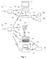
- the communication system shown in Fig. 1 has a first Signal source 1, which is provided for the distribution of television signals 17 which are received via cable, satellite or terrestrial.
- the signals 17 of the signal source 1 become a signal processing device 4 supplied, the signal conditioning device 4 is used to distribute the Signals 17 to terminals 2, 3, 5.
- the terminals 2, 3, 5 are in the in Fig. 1st illustrated embodiment, a TV receiver 2 with a Receiving device 2a, a screen 3 and a radio receiving device 5 with a receiving part 5a.
- a radio interface 27 is provided between TV reception equipment 2 and radio receiver 5 is also a radio interface 27 is provided.
- the transmission of signals 17 between the signal conditioning device 4 and the television or Radio receivers 2, 5 take place wirelessly via radio interfaces 19, 20.
- the signals received by the radio receiver 5, can further radio interfaces 21, 22, for example as Infrared interfaces are formed, distributed to speakers 6a, 6b will.
- the communication system shown in Fig. 1 has furthermore a second signal source 10 for receiving Telephone signals 18 on.
- the telephone signals 18 become a second Signal processing device 11 supplied via radio interfaces 23 ... 26 can be connected to end devices 12 .. 16.
- a connection between stationary 15 and portable personal computer 15 is over another Interface 32 possible.
- the communication system shown in Fig. 1 also shows a connection option shown in dashed lines between the signal conditioning devices 4 and 11, whereby a Connection of the different signal sources is possible.
- a coupling of the TV receiving device is also via a radio interface 28 2 to the second signal source 10.
- the communication system shown in Fig. 1 is based on a decentralized structure of signal sources 1, 10, i.e. the signal sources 1, 10 or the corresponding signal processing devices 4, 11 are with the respective end devices 2, 3, 5 - 12 ... 15 directly via the wireless in-house connection connected.
- Such a decentralized structure of the Communication system has the advantage that all services of the signal sources 1, 10 distributed directly at the respective location where these are available can be without being central to a data stream must be summarized. This can be an additional Cabling effort to an otherwise necessary central station be avoided.
- Signal source 1 is, for example a data source that provides television signals over the Connection line 17 supplied to the signal conditioning device 4 will.
- the signal conditioning device 4 is used for decoding the TV signals supplied by the signal source 1 and for the radiation of the appropriately prepared television signals to the respective terminals 2, 3, 5. Through the wireless connection of the terminals 2, 3, 5 to the Signal conditioning device 4 is therefore not required, for example an additional wiring effort for a residential unit.
- the connection of the terminals 2, 3, 5 to the signal processing device 4 takes place via the air interfaces 19, 20.
- the Signal source 10 telephone signals supplied via the connecting line 18 from the second signal processing device 11 to the one with this connectable terminals 12 ... 15 transmitted.
- Via connecting line 19 or by direct connection to the respective Signal conditioning device it is also possible that certain Terminal devices, such as the PC 15 with several signal sources 1, 10 communicates.
- Fig. 1 shown communication system terminals that on none Access service, such as that shown in Fig. 1 Speakers 6a, 6b and the printer 16 is the case. Beyond that also provided terminals that use only a single service, such as this is the case for example with the telephone 12, 13. Overall arises through the communication system shown in Fig. 1 a flexible Connection to the corresponding signal sources 1, 10. So that a direct parallel access of the different end devices to the different ones Signal sources 1, 10 are possible, the Signal conditioning devices 4, 11 and the terminals 2, 3, 5; 12 ... 15 corresponding modems that address the registration or deregistration to serve.
- a channel access method such as for example CDMA, TDMA or FDMA or a combination of these Procedure used.
- CDMA Code Division Multiple Access
- TDMA Time Division Multiple Access
- FDMA Frequency Division Multiple Access
- this method offers one increased security in relation to data protection problems.
- About the Radio interface 28 between the TV receiver 2 and Signal conditioning device 11 for the second signal source 10 is for example, receiving faxes or accessing Communication services, such as the Internet, are possible.
- the house or housing unit to be supplied consists of Clear R1, R2, R3, R4.
- room R1 there is a connection 1 to Reception of television signals, for example via cable, satellite or via terrestrial reception options.
- connection 10 is provided, for example as an ISDN telephone connection is trained. Via these decentrally arranged connections 1, 10 the entire residential unit R1 ... R4 is supplied. So are in Room R4 a TV receiver unit 2 with monitor or TV receiver 3 available. Are in room R4 in addition, two speakers 6a, 6b, for example via wireless Infrared connection to the television 3 are coupled.
- the transmitting devices e.g. the decoder for digital TV 2 directly with the respective Receiving devices, e.g. connected to the television 3.
- This is done right at the place of origin for every service that is for the residents of the Housing unit is provided, the implementation on the wireless In-house connection.
- a complex implementation in a central Data stream that supplies several services centrally, for example, is thus dispensable.
- An additional cabling effort in the cabling of centrally planned structures would also be necessary superfluous.
- the communication system shown in Fig. 2 has in addition, a very high flexibility, since a structure in small Steps towards a complex system according to the respective Requirements is possible without much effort.
- the signal source 1 for receiving television programs access both the receiving device 2 and the PC 15.
- the signal processing device 4 for the respective signal sources 1, 10 take place where the signal sources for Are available or where the services are needed in close proximity.
- the respective transmission power / reception power of the Signal conditioning devices 4, 10 or the respective terminals 2, 3; 12, 15 can thus be reduced to a minimum.
- the Communication system a corresponding reception power regulation (Power Control) on.
- This receive / transmit power regulation is such trained that the receiver when placed directly next to the transmitter is set to minimum reception power and at maximum distance or additional damping, for example through walls, its full Delivers receiving power.
- the communication system also communication with others Services, for example via radio communication service such as GSM or DAB services that can be integrated.
- FIG. 3 shows another embodiment of a local and wireless Communication system.
- the communication system shown in Fig. 3 consists of signal sources 1, 10 with respective Signal conditioning devices 4, 11. Die Signal processing devices, 4, 11 are for processing television or Telephone signals provided.
- the signal processing devices 4, 11 are connected to a device 2 via radio interfaces 43, 44, that as an interface to a television set 3 and more Radio interfaces 45, 46 to a heating control device 41 and one Safety control device 42 is used.
- the Heater control device 41 is connected to the heating center 40 coupled while the safety control device 42 with for example, signal generators arranged on windows, doors, etc. connected is.
Abstract
Description
Die Erfindung betrifft ein Kommunikationssystem mit mindestens zwei voneinander unabhängigen Signalquellen.The invention relates to a communication system with at least two independent signal sources.
Bei einem derartigen Kommunikationssystem handelt es sich beispielsweise
um ein sogenanntes ![]()
![]()
Der Erfindung liegt die Aufgabe zugrunde, ein Kommunikationssystem anzugeben, das ohne zusätzliche Verkabelung einen Zugriff auf unterschiedliche Dienste innerhalb eines Hauses ermöglicht.The invention has for its object a communication system specify that access without additional wiring enables different services within a house.
Diese Aufgabe wird durch ein Kommunikationssystem mit den im Anspruch 1
angegebenen Merkmalen gelöst.This object is achieved by a communication system with the in
Grundkonzept eines derartigen Kommunikationssystems ist somit seine dezentrale Struktur. Bei einer derartigen dezentralen Struktur ist eine gemeinsame Luftschnittstelle für die Endgeräte vorgesehen. In dieser Luftschnittstelle sind sowohl der logische Kontrollkanal bzw. die Kontrollkanäle als auch die jeweiligen Datenkanäle wiederzufinden. Mit Hilfe eines kontinuierlichen Kontrollkanals kann die Intelligenz des Netzwerks auf die verschiedenen Geräte verteilt werden. Damit kann jedes Gerät selbst entscheiden, ob ein Kanalzugriff möglich ist oder nicht. Die Signalquellen der externen Diensteanbieter, wie beispielsweise TV-Dienste, Telefondienste, Rundfunkdienste etc., werden direkt mit den jeweiligen Endgeräten, wie beispielsweise TV-, Rundfunkempfangseinrichtung oder Telefonendgerät, verbunden. Hierdurch erfolgt die Umsetzung auf die beispielsweise als drahtlose In-House-Verbindung ausgebildete Schnittstelle zum Endgerät ohne zusätzlichen Aufwand für die Zuführung zu einer zentralen Stelle. Bei einer bidirektionalen Verbindung, wie dies beispielsweise in jedem Fall bei Telefondiensten erforderlich ist, ergibt sich im Vergleich zu einer zentralen Struktur des Kommunikationssystems, d.h. bei einer indirekten Verbindung beispielsweise zu einem ersten Endgerät über eine Zentrale zu einem zweiten Endgerät, ein großer Vorteil im Hinblick auf die benötigte Bandbreite. Im Vergleich zur vorgeschlagenen direkten Verbindung wird in diesem Fall nämlich die doppelte Bandbreite benötigt.The basic concept of such a communication system is therefore its decentralized structure. With such a decentralized structure, one is common air interface provided for the terminals. In this Air interface are both the logical control channel and the Find control channels as well as the respective data channels again. With help a continuous control channel can affect the intelligence of the network the different devices are distributed. Each device can do this itself decide whether channel access is possible or not. The signal sources the external service provider, such as TV services, Telephone services, broadcasting services, etc. are directly with the respective Terminals, such as TV, radio reception equipment or Telephone terminal connected. As a result, the implementation takes place on the for example, an interface designed as a wireless in-house connection to the end device without additional effort for feeding to one central location. With a bidirectional connection like this for example, is required in any case for telephone services compared to a central structure of the communication system, i.e. in the case of an indirect connection, for example to a first terminal via a central to a second terminal, a big advantage in terms of to the required bandwidth. Compared to the proposed direct In this case, the connection requires twice the bandwidth.
Eine direkte von dem jeweiligen Ort, an dem die verschiedenen Dienste zur Verfügung stehen, ausgehende Verteilung der Dienste wird dadurch erreicht, daß das Kommunikationssystem zur Verteilung der von den Signalquellen der externen Diensteanbieter gelieferten Signale jeweils eine Signalaufbereitungseinrichtung aufweist, die zur Verteilung der Signale jeweils an die entsprechenden Endgeräte vorgesehen sind.A direct from the respective location where the various services for This will provide outbound distribution of services achieved that the communication system for the distribution of the Signal sources of the external service providers each delivered signals Signal conditioning device, which is used to distribute the signals are each provided on the corresponding terminals.
Auf eine zusätzliche Verkabelung zur Verteilung der Dienste kann dadurch verzichtet werden, daß mindestens eine Signalaufbereitungseinrichtung und mindestens ein Endgerät Mittel zur drahtlosen, bidirektionalen Verbindung aufweisen.This enables additional cabling to be used to distribute the services be dispensed with that at least one signal processing device and at least one terminal means for wireless, bidirectional connection exhibit.
Eine umfassende Kommunikation ohne unnötige Belastung der zwischen Signalaufbereitungseinrichtung und Endgerät zur Verfügung stehenden Verbindungen kann dadurch gewährleistet werden, daß das Kommunikationssystem weitere Endgeräte aufweist, die nicht direkt auf die externen Signalquellen zugreifen und als Terminals für die zur Verbindung mit den Signalaufbereitungseinrichtungen vorgesehenen Endgeräten vorgesehen sind. Comprehensive communication without unnecessary stress between the Signal processing device and terminal available Connections can be ensured that the Communication system has other devices that are not directly on the access external signal sources and as terminals for connecting with the signal processing devices provided terminals are provided.
Eine besonders vorteilhafte Realisierung der Verbindungen wird dadurch erreicht, daß das Kommunikationssystem nach einem Kanalzugriffsverfahren, insbesondere nach einem TDMA- und/oder einem FDMA-Verfahren arbeitet.This makes a particularly advantageous realization of the connections achieved that the communication system after a Channel access method, in particular according to a TDMA and / or FDMA process works.
Eine vorteilhafte kostengünstige Verbindung zwischen benachbarten Endgeräten ist die, daß zur Verbindung zwischen stationären oder quasistationären Endgeräten eine Infrarot-Verbindung vorgesehen ist.An advantageous low-cost connection between neighboring ones Terminal equipment is that for the connection between stationary or quasi-stationary terminals an infrared connection is provided.
Die Belastungen in Form von hochfrequenten Strahlungen kann dadurch auf ein Minimum reduziert werden, daß die Signalaufbereitungseinrichtungen und die Endgeräte Mittel zur Regelung der Sendeleistung aufweisen.The exposure in the form of high-frequency radiation can thereby be reduced to a minimum that the signal conditioning devices and the terminals have means for regulating the transmission power.
Ein Mißbrauch von Diensten kann dadurch verhindert werden, daß das Kommunikationssystem Mittel zur Kontrolle einer Zugangsberechtigung zu bestimmten Diensten aufweist.Abuse of services can be prevented by the fact that Communication system means to control an access authorization has certain services.
Eine für bestehende und kommende Anforderungen ausreichende Konfiguration des Kommunikationssystems wird dadurch erreicht, daß die Signalaufbereitungseinrichtungen zur Aufbereitung von analogen und/oder digitalen Ton- und/oder Bildsignalen, insbesondere von Rundfunk-, Fernseh- und/oder Telefonsignalen vorgesehen sind.A sufficient for existing and upcoming requirements Configuration of the communication system is achieved in that the Signal conditioning devices for conditioning analog and / or digital audio and / or video signals, in particular radio, television and / or Telephone signals are provided.
Der jeweilige Datentransfer zwischen den Signalsenken und den Endgeräten erfolgt dadurch, daß die Signalaufbearbeitungseinrichtungen und die Endgeräte jeweils ein Modem zum Zugriff auf die externen Dienste und zur Anpassung an die jeweilige Kommunikation zwischen Signalaufbearbeitungseinrichtung und Endgerät aufweisen.The respective data transfer between the signal sinks and the end devices takes place in that the signal processing devices and the Terminal devices each have a modem for access to external services and Adaptation to the respective communication between Have signal processing device and terminal.
Im folgenden wird die Erfindung anhand der in den Figuren dargestellten Ausführungsbeispiele näher beschrieben und erläutert. In the following, the invention is illustrated by the figures Exemplary embodiments described and explained in more detail.
Es zeigen:
- Fig. 1
- ein erstes Ausführungsbeispiel eines Kommunikationsnetzes und
- Fig. 2
- ein weiteres Ausführungsbeispiel eines IN-House-Kommunikationsnetzes und
- Fig. 3
- ein weiteres Ausführungsbeispiel eines IN-House-Kommunikationsnetzes mit Heizungssteuerung und Überwachungseinrichtung.
- Fig. 1
- a first embodiment of a communication network and
- Fig. 2
- a further embodiment of an IN-house communication network and
- Fig. 3
- a further embodiment of an IN-house communication network with heating control and monitoring device.
Das in Fig. 1 dargestellte Kommunikationssystem weist eine erste
Signalquelle 1 auf, die zur Verteilung von Fernsehsignalen 17 vorgesehen
ist, die über Kabel, Satellit oder terrestrisch empfangen werden. Die Signale
17 der Signalquelle 1 werden einer Signalaufbereitungseinrichtung 4
zugeführt, die Signalaufbereitungseinrichtung 4 dient der Verteilung der
Signale 17 an Endgeräte 2, 3, 5. Die Endgeräte 2, 3, 5 sind bei dem in Fig. 1
dargestellten Ausführungsbeispiel ein TV-Empfänger 2 mit einer
Empfangseinrichtung 2a, ein Bildschirm 3 sowie eine Rundfunk-Empfangseinrichtung
5 mit einem Empfangsteil 5a. Zwischen TV-Empfangseinrichtung
2 und Rundfunk-Empfangseinrichtung 5 ist ebenfalls
eine Funkschnittstelle 27 vorgesehen. Die Übertragung der Signale 17
zwischen der Signalaufbereitungseinrichtung 4 und dem Fernseh- bzw.
Rundfunkempfänger 2, 5 erfolgt dabei drahtlos über Funkschnittstellen 19,
20. Die vom Rundfunkempfänger 5 empfangenen Signale, können über
weitere Funkschnittstellen 21, 22, die beispielsweise als
Infrarotschnittstellen ausgebildet sind, an Lautsprecher 6a, 6b verteilt
werden. Das in Fig. 1 dargestellte Kommunikationssystem weist
darüberhinaus eine zweite Signalquelle 10 zum Empfang von
Telefonsignalen 18 auf. Die Telefonsignale 18 werden einer zweiten
Signalaufbereitungseinrichtung 11 zugeführt, die über Funkschnittstellen 23
...26 mit Endgeräten 12.. 16 verbindbar ist. Als Endgeräte sind bei dem in
Fig. 1 dargestellten Ausführungsbeispiel ein Telefonapparat 12, ein
schnurloser Telefonapparat 13, ein tragbarer Personalcomputer 14 sowie
ein stationärer Personalcomputer 15 mit über eine Schnittstelle 31
anschließbarem Drucker 16 vorgesehen. Eine Verbindung zwischen
stationärem 15 und tragbarem Personalcomputer 15 ist über eine weitere
Schnittstelle 32 möglich. Das in Fig. 1 dargestellte Kommunikationssystem
weist darüberhinaus eine gestrichelt eingezeichnete Verbindungsmöglcihkeit
zwischen den Signalaufbereitungseinrichtungen 4 und 11 auf, wodurch eine
Verbindung der verschiedenen Signalquellen möglich wird. Außerdem ist
über eine Funkschnittstelle 28 auch eine Kopplung der TV-Empfangseinrichtung
2 an die zweite Signalquelle 10 vorgesehen.The communication system shown in Fig. 1 has a
Das in Fig. 1 dargestellte Kommunikationssystem beruht auf einer
dezentralen Struktur der Signalquellen 1, 10, d.h. die Signalquellen 1, 10
bzw. die entsprechenden Signalaufbereitungseinrichtungen 4, 11 sind mit
den jeweiligen Endgeräten 2, 3, 5 - 12... 15 direkt über die drahtlose In-House-Verbindung
verbunden. Eine derartige dezentrale Struktur des
Kommunikationssystems hat den Vorteil, daß alle Dienste der Signalquellen
1, 10 am jeweiligen Ort, wo diese zur Verfügung stehen, direkt verteilt
werden können, ohne daß sie zentral zu einem Datenstrom
zusammengefaßt werden müssen. Hierdurch kann ein zusätzlicher
Verkabelungsaufwand zu einer ansonsten notwendigen Zentralstation
vermieden werden. Bei der Signalquelle 1 handelt es sich beispielsweise um
eine Datenquelle, die Fernsehsignale bereitstellt, die über die
Verbindungsleitung 17 an die Signalaufbereitungseinrichtung 4 geliefert
werden. Die Signalaufbereitungseinrichtung 4 dient zur Decodierung der
von der Signalquelle 1 gelieferten Fernsehsignale sowie zur Abstrahlung der
entsprechend aufbereiteten Fernsehsignale an die jeweiligen Endgeräte 2,
3, 5. Durch die drahtlose Anbindung der Endgeräte 2, 3, 5 an die
Signalaufbereitungseinrichtung 4 entfällt somit innerhalb beispielsweise
einer Wohneinheit ein zusätzlicher Verkabelungsaufwand. Die Anbindung
der Endgeräte 2, 3, 5 an die Signalaufbereitungseinrichtung 4 erfolgt über
die Luftschnittstellen 19, 20. In entsprechender Weise werden die von der
Signalquelle 10 über die Verbindungsleitung 18 gelieferten Telefonsignale
von der zweiten Signalaufbereitungseinrichtung 11 an die mit dieser
koppelbaren Endgeräte 12 ... 15 übermittelt. Über eine Verbindungsleitung
19 bzw. durch direkte Anbindung an die jeweilige
Signalaufbereitungseinrichtung ist es auch möglich, daß bestimmte
Endgeräte, wie beispielsweise der PC 15 mit mehreren Signalquellen 1, 10
in Verbindung steht. Hierdurch wird es beispielsweise möglich, daß der PC
15 auch Signale aus der Signalquelle 1 empfangen kann. Somit weist das in
Fig. 1 dargestellte Kommunikationssystem Endgeräte auf, die auf keinen
Dienst zugreifen, wie dies beispielsweise bei den in Fig. 1 dargestellten
Lautspechern 6a, 6b sowie dem Drucker 16 der Fall ist. Darüberhinaus sind
auch Endgeräte vorgesehen, die lediglich einen einzigen Dienst nutzen, wie
dies beispielsweise bei dem Telefon 12, 13 der Fall ist. Insgesamt entsteht
durch das in Fig. 1 dargestellte Kommunikationssystem eine flexible
Anbindung an die entsprechenden Signalquellen 1, 10. Damit ein direkter
paralleler Zugriff der verschiedenen Endgeräte auf die unterschiedlichen
Signalquellen 1, 10 möglich ist, weisen die
Signalaufbereitungseinrichtungen 4, 11, sowie die Endgeräte 2, 3, 5; 12... 15
entsprechende Modems, die der Adressierung der An- bzw. Abmeldung
dienen. Als Übertragungsverfahren wird ein Kanalzugriffsverfahren, wie
beispielsweise CDMA, TDMA oder FDMA bzw. eine Kombination dieser
Verfahren verwendet. Als robustes Verfahren ist in dieser Hinsicht das
CDMA-Verfahren in Kombination mit dem Spread-Spektrum
Modulationsverfahren geeignet. Darüberhinaus bietet dieses Verfahren eine
erhöhte Sicherheit in Bezug auf eine Datenschutzproblematik. Über die
Funkschnittstelle 28 zwischen TV-Empfangseinrichtung 2 und
Signalaufbereitungseinrichtung 11 für die zweite Signalquelle 10 ist
beispielsweise ein Empfang von Telefaxnachrichten oder ein Zugriff auf
Kommunikationsdienste, wie beispielsweise das Internet möglich.The communication system shown in Fig. 1 is based on a
decentralized structure of
Fig. 2 zeigt ein weiteres Ausführungsbeispiel eines Kommunikationssystems
am Beispiel eines möglichen Szenarios eines drahtlosen In-House-Netzes.
Das zu versorgende Haus bzw. zu versorgende Wohneinheit besteht aus
Räumen R1, R2, R3, R4. Im Raum R1 befindet sich ein Anschluß 1 zum
Empfang von Fernsehsignalen beispielsweise über Kabel, Satellit bzw. über
terrestrische Empfangsmöglichkeiten. Im Raum R1 ist darüberhinaus ein
Anschluß 10 vorgesehen, der beispielsweise als ISDN-Telefonanschluß
ausgebildet ist. Über diese jeweils dezentral angeordneten Anschlüsse 1, 10
erfolgt die Versorgung der kompletten Wohneinheit R1...R4. So sind im
Raum R4 eine TV-Empfangseinheit 2 mit Monitor bzw.
Fernsehempfangsgerät 3 vorhanden. Im Raum R4 befinden sich
darüberhinaus zwei Lautsprecher 6a, 6b, die beispielsweise über drahtlose
Infrarotanbindung an das Fernsehgerät 3 gekoppelt sind. Im Raum R1 ist ein
tragbarer Personalcomputer 14a vorgesehen, der mit der
Signalaufbereitungseinrichtung 11, der Signalquelle 10 sowie mit einem
stationär installierten Computer 15 Raum R2 koppelbar ist. Im Raum R2
befindet sich darüberhinaus ein Drucker 16, der über eine
Infrarotschnittstelle mit dem fest installierten PC 15 verbindbar ist, während
im Raum R3 ein weiterer tragbarer Personalcomputer 14b sowie ein
schnurloser Telefonapparat 12 vorhanden sind.2 shows a further exemplary embodiment of a communication system
using the example of a possible scenario of a wireless in-house network.
The house or housing unit to be supplied consists of
Clear R1, R2, R3, R4. In room R1 there is a
Durch die in Fig. 2 gezeigte dezentrale Netzstruktur sind die Sendegeräte,
z.B. der Decoder für digitale TV 2 direkt mit den jeweiligen
Empfangsgeräten, z.B. mit dem Fernsehgerät 3 verbunden. Hierdurch erfolgt
direkt am Entstehungsort für jeden Dienst, der für die Bewohner der
Wohneinheit zur Verfügung gestellt wird, die Umsetzung auf die drahtlose
In-House-Verbindung. Eine aufwendige Umsetzung in einen zentralen
Datenstrom, der beispielsweise mehrere Dienste zentral versorgt, ist somit
entbehrlich. Ein zusätzlicher Verkabelungsaufwand, der bei der Verkabelung
von zentral vorgesehenen Strukturen erforderlich wäre, ist somit ebenfalls
überflüssig. Das in Fig. 2 dargestellte Kommunikationssystem weist
darüberhinaus eine sehr hohe Flexibilität aus, da ein Aufbau in kleinen
Schritten hin zu einem komplexen System entsprechend den jeweiligen
Anforderungen ohne großen Aufwand möglich ist. Darüberhinaus können
bereits vorhandene Geräte innerhalb des Kommunikationssystems wie
beispielsweise ein ohnehin vorhandener Fernsehapparat oder
Personalcomputer weiter verwendet werden. Lediglich sind die ggfs.
benötigten Schnittstellen zu ergänzen. Auf Grund der dezentralen
Netzstruktur ist es darüberhinaus möglich, daß mehrere Empfänger einen
gleichzeitigen Zugang zu einer Signalquelle haben. So können
beispielsweise auch die Signalquelle 1 zum Empfang von Fernsehprogramm
sowohl die Empfangseinrichtung 2, als auch der PC 15 zugreifen. Bei der
Planung des in Fig. 2 dargestellten Kommunikationssystems kann eine
lokale Anordnung der jeweiligen Signalaufbereitungseinrichtung 4, 11 für die
jeweiligen Signalquellen 1, 10 jeweils dort erfolgen, wo die Signalquellen zur
Verfügung stehen oder wo die Dienste in räumlicher Nähe benötigt werden.
Bei einer Anordnung in räumlicher Nähe zu den jeweiligen Endgeräten kann
die jeweilige Sendeleistung/Empfangsleistung der
Signalaufbereitungseinrichtungen 4, 10 bzw. der jeweiligen Endgeräte 2, 3;
12, 15 somit auf ein Minimum reduziert werden. Hierzu weist das
Kommunikationssystem eine entsprechende Empfangsleistungsregelung
(Power Control) auf. Diese Empfangs/Sendeleistungsregelung ist derart
ausgebildet, daß der Empfänger bei direkter Plazierung neben dem Sender
auf minimale Empfangsleistung eingestellt ist und bei maximaler Distanz
oder zusätzlicher Dämpfung beispielsweise durch Wände seine volle
Empfangsleistung abgibt. Durch das außerhalb der Wohneinheit
vorgesehene Bezugszeichen 30 mit entsprechendem Pfeil ist symbolisiert,
daß in das Kommunikationssystem auch die Kommunikation mit weiteren
Diensten, beispielsweise über Funkkommunikationsdienst wie GSM oder
DAB-Dienste, eingebunden werden kann.Due to the decentralized network structure shown in FIG. 2, the transmitting devices
e.g. the decoder for
Fig. 3 zeigt ein weiteres Ausführungsbeispiel eines lokalen und drahtlosen
Kommunikationssystems. Das in Fig. 3 dargestellte Kommunikationssystem
besteht aus Signalquellen 1, 10 mit jeweiligen
Signalaufbereitungseinrichtungen 4, 11. Die
Signalaufbereitungseinrichtungen, 4, 11 sind zur Aufbereitung von Fernseh- bzw.
Telefonsignalen vorgesehen. Die Signalaufbereitungseinrichtungen 4,
11 sind über Funkschnittstellen 43, 44 mit einer Einrichtung 2 verbunden,
die als Schnittstelle zu einem Fernsehgerät 3 sowie über weitere
Funkschnittstellen 45, 46 zu einer Heizungssteuereinrichtung 41 sowie einer
Sicherheitssteuerungseinrichtung 42 dient. Die
Heizungssteuerungseinrichtung 41 ist an die Heizungszentrale 40
angekoppelt, während die Sicherheitssteuerungseinrichtung 42 mit
beispielsweise an Fenstern, Türen etc. angeordneten Signalgebern
verbunden ist.3 shows another embodiment of a local and wireless
Communication system. The communication system shown in Fig. 3
consists of
Mit Hilfe des in Fig. 3 dargestellten Kommunikationssystems ist neben den
im Zusammenhang mit den Fig. 1 und 2 beschriebenen Diensten auch eine
Steuerung der Heizungsanlage 40 sowie einer Alarmanlage 42 möglich.
Über die drahtlose Anbindung an die Telefonschnittstelle 10, 11 ist auch
eine Steuerung der Heizungsanlage 40 sowie der Sicherungsanlage 42
möglich. Der Anwendungsbereich der jeweiligen Kommunikationssysteme in
den Fig. 1 - 3 ist neben der gezeigten Konfiguration auch in beliebigen
Kombinationen untereinander möglich.With the help of the communication system shown in FIG. 3, in addition to the
in connection with FIGS. 1 and 2 also described services
Control of the
Claims (10)
dadurch gekennzeichnet,
daß das Kommunikationssystem zur Verteilung der von den Signalquellen (1, 10) der externen Diensteanbieter gelieferten Signale (17, 18) jeweils eine Signalaufbereitungseinrichtung (4, 11) aufweist, die zur Verteilung der Signale (17, 18) jeweils an die entsprechenden Endgeräte (2, 3, 5 ; 11 .. 16) vorgesehen ist.Communication system according to claim 1,
characterized,
that the communication system for distributing the signals (17, 18) supplied by the signal sources (1, 10) of the external service providers each has a signal processing device (4, 11) which, in order to distribute the signals (17, 18) to the corresponding terminals ( 2, 3, 5; 11 .. 16) is provided.
dadurch gekennzeichnet,
daß mindestens eine Signalaufbereitungseinrichtung (4, 11) und mindestens ein Endgerät (2, 3, 5 ; 11 .. 16) Mittel zur drahtlosen, bidirektionalen Verbindung aufweisen.Communication system according to one of claims 1 or 2,
characterized,
that at least one signal conditioning device (4, 11) and at least one terminal (2, 3, 5; 11 .. 16) have means for wireless, bidirectional connection.
dadurch gekennzeichnet,
daß das Kommunikationssystem weitere Endgeräte (6a, 6b, 16) aufweist, die nicht direkt auf die externen Signalquellen (1, 10) zugreifen und als Terminals für die zur Verbindung mit den Signalaufbereitungseinrichtungen (4, 11) vorgesehenen Endgeräten (2, 3, 5 ; 11 .. 16) vorgesehen sind.Communication system according to one of claims 1 to 3,
characterized,
that the communication system has further terminals (6a, 6b, 16) that do not directly access the external signal sources (1, 10) and as terminals for the terminals (2, 3, 5) provided for connection to the signal conditioning devices (4, 11) ; 11 .. 16) are provided.
dadurch gekennzeichnet,
daß das Kommunikationssystem nach einem Kanalzugriffsverfahren, insbesondere nach einem TDMA- und/ der einem FDMA-Verfahren arbeitet.Communication system according to one of claims 1 to 4,
characterized,
that the communication system operates according to a channel access method, in particular according to a TDMA and / or an FDMA method.
dadurch gekennzeichnet,
daß zur Verbindung zwischen stationären oder quasistatoinären Endgeräten (5, 6a, 6b) eine Infrarot-Verbindung vorgesehen ist.Communication system according to one of claims 1 to 5,
characterized,
that an infrared connection is provided for the connection between stationary or quasi-static end devices (5, 6a, 6b).
dadurch gekennzeichnet,
daß die Signalaufbereitungseinrichtungen (4, 11) und die Endgeräte (2, 3, 5 ; 11 .. 16) Mittel zur Regelung der Sendeleistung aufweisen.Communication system according to one of claims 1 to 6,
characterized,
that the signal conditioning devices (4, 11) and the terminals (2, 3, 5; 11 .. 16) have means for regulating the transmission power.
dadurch gekennzeichnet,
daß das Kommunikationssystem Mittel zur Kontrolle einer Zugangsberechtigung zu bestimmten Diensten aufweist.Communication system according to one of claims 1 to 7,
characterized,
that the communication system has means for controlling access authorization to certain services.
dadurch gekennzeichnet,
daß die Signalaufbereitungseinrichtungen (4, 11) zur Aufbereitung von analogen und/oder digitalen Ton- und/oder Bildsignalen, insbesondere von Rundfunk-, Fernseh- und/oder Telefonsignalen vorgesehen sind.Communication system according to one of claims 1 to 8,
characterized,
that the signal processing devices (4, 11) are provided for processing analog and / or digital audio and / or video signals, in particular radio, television and / or telephone signals.
dadurch gekennzeichnet,
daß die Signalaufbereitungseinrichtungen (4, 11) und die Endgeräte (2, 3, 5 ; 11 .. 16) jeweils ein Modem zum Zugriff auf die externen Dienste (1, 10) und zur Anpassung an die jeweilige Kommunikation zwischen Signalverarbeitunseinrichtung (4, 11) und Endgerät (2, 3, 5 ; 11 .. 16) aufweisen.Communication system according to one of claims 1 to 9,
characterized,
that the signal processing devices (4, 11) and the terminals (2, 3, 5; 11 .. 16) each have a modem for accessing the external services (1, 10) and for adapting to the respective communication between signal processing device (4, 11 ) and terminal (2, 3, 5; 11 .. 16).
Applications Claiming Priority (2)
| Application Number | Priority Date | Filing Date | Title |
|---|---|---|---|
| DE1997110169 DE19710169A1 (en) | 1997-03-12 | 1997-03-12 | Decentralized communication system |
| DE19710169 | 1997-03-12 |
Publications (2)
| Publication Number | Publication Date |
|---|---|
| EP0865168A2 true EP0865168A2 (en) | 1998-09-16 |
| EP0865168A3 EP0865168A3 (en) | 2003-09-03 |
Family
ID=7823097
Family Applications (1)
| Application Number | Title | Priority Date | Filing Date |
|---|---|---|---|
| EP98103884A Ceased EP0865168A3 (en) | 1997-03-12 | 1998-03-05 | Decentralized communications system |
Country Status (2)
| Country | Link |
|---|---|
| EP (1) | EP0865168A3 (en) |
| DE (1) | DE19710169A1 (en) |
Cited By (2)
| Publication number | Priority date | Publication date | Assignee | Title |
|---|---|---|---|---|
| WO2002003691A1 (en) * | 2000-06-30 | 2002-01-10 | Fast Tv Server Ag | Method for providing information on a tv set |
| US7274831B2 (en) | 2003-04-03 | 2007-09-25 | Microsoft Corporation | High quality anti-aliasing |
Citations (1)
| Publication number | Priority date | Publication date | Assignee | Title |
|---|---|---|---|---|
| US5101499A (en) * | 1987-09-15 | 1992-03-31 | Jerry R. Iggulden | Television local wireless transmission and control |
Family Cites Families (10)
| Publication number | Priority date | Publication date | Assignee | Title |
|---|---|---|---|---|
| DE4001810C2 (en) * | 1990-01-23 | 1996-02-08 | Loewe Opta Gmbh | Energy saving circuit in a mobile device for wireless communication |
| JPH05284203A (en) * | 1990-04-05 | 1993-10-29 | Texas Instr Inc <Ti> | Method and system for user interface for speaking based on telecommunication |
| DE4227914A1 (en) * | 1992-08-22 | 1994-02-24 | Sensys Ag | Cordless IR telephone subscriber's installation - has telephones connected via IR repeaters and channels for analog speech signals and digital data pilot channel |
| US5325423A (en) * | 1992-11-13 | 1994-06-28 | Multimedia Systems Corporation | Interactive multimedia communication system |
| CA2137383C (en) * | 1994-01-03 | 2001-02-13 | Gary Len Griffith | A switching arrangement for handling wireless terminals with switch features for handling wired terminals |
| US5459779A (en) * | 1994-02-25 | 1995-10-17 | At&T Ipm Corp. | Method for switching telephone calls to information service providers |
| US5537467A (en) * | 1994-08-23 | 1996-07-16 | Bell Communications Research, Inc. | Method for forwarding a call to a temporarily utilized portable telephone |
| DE19514616A1 (en) * | 1995-04-25 | 1996-10-31 | Sel Alcatel Ag | Communication system with hierarchical server structure |
| US5610910A (en) * | 1995-08-17 | 1997-03-11 | Northern Telecom Limited | Access to telecommunications networks in multi-service environment |
| DE19538842A1 (en) * | 1995-10-19 | 1997-04-24 | Walter Dipl Ing Siepmann | Mobile telephone with connection to data processing system |
-
1997
- 1997-03-12 DE DE1997110169 patent/DE19710169A1/en not_active Ceased
-
1998
- 1998-03-05 EP EP98103884A patent/EP0865168A3/en not_active Ceased
Patent Citations (1)
| Publication number | Priority date | Publication date | Assignee | Title |
|---|---|---|---|---|
| US5101499A (en) * | 1987-09-15 | 1992-03-31 | Jerry R. Iggulden | Television local wireless transmission and control |
Non-Patent Citations (3)
| Title |
|---|
| CHOW P.S.; CIOFFI J.M.: 'A MULTI-DROP IN-HOUSE ADSL DISTRIBUTION NETWORK' IEEE INTERNATIONAL CONFERENCE 01 Mai 1994, USA, XP010126562 * |
| MOSEL H J: "HOME COMMUNICATION SYSTEMS" IEEE JOURNAL ON SELECTED AREAS IN COMMUNICATIONS, IEEE INC. NEW YORK, US, Bd. SAC - 4, Nr. 4, 1. Juli 1986 (1986-07-01), Seiten 633-639, XP000313573 ISSN: 0733-8716 * |
| WILLIAM STALLINGS: "Local & Metropolitan Area Networks" 1. Januar 1997 (1997-01-01) , PRENTICE-HALL , USA XP002244034 * Abbildung 11.7 * * |
Cited By (4)
| Publication number | Priority date | Publication date | Assignee | Title |
|---|---|---|---|---|
| WO2002003691A1 (en) * | 2000-06-30 | 2002-01-10 | Fast Tv Server Ag | Method for providing information on a tv set |
| DE10031121A1 (en) * | 2000-06-30 | 2002-01-17 | Fast Tv Server Ag | Method for providing information on a television set |
| DE10031121B4 (en) * | 2000-06-30 | 2006-10-05 | Sony United Kingdom Ltd., Brooklands | Method for providing information on a television |
| US7274831B2 (en) | 2003-04-03 | 2007-09-25 | Microsoft Corporation | High quality anti-aliasing |
Also Published As
| Publication number | Publication date |
|---|---|
| DE19710169A1 (en) | 1998-09-17 |
| EP0865168A3 (en) | 2003-09-03 |
Similar Documents
| Publication | Publication Date | Title |
|---|---|---|
| DE69631372T2 (en) | Leakage cable transmission system and corresponding equipment for a subscriber facility | |
| DE69833757T2 (en) | Automated home control system using the existing power lines as a transmission medium | |
| DE19702350B4 (en) | Central node converter for connection to a connection of a house network, which is connected with a coaxial cable, and method for communication | |
| EP1719367B1 (en) | Multiple use of a standard interface in a device | |
| DE19848899A1 (en) | Personal computer based set-top converter for television services | |
| EP0731619B1 (en) | Broadband communication system and method | |
| DE4119094A1 (en) | Intelligent remote measuring and setting system using e.g. radio network - has mobile unit, e.g. handset connected to network via modem operating with single carrier frequency using signal converter | |
| EP0865168A2 (en) | Decentralized communications system | |
| CH647627A5 (en) | Cable communication system | |
| EP2154884B1 (en) | Antenna socket | |
| EP0933884B1 (en) | Transmission power adjustment particularly for wireless in-house communication | |
| EP0059786B1 (en) | Antenna socket | |
| EP1182872B1 (en) | Communication system | |
| EP0419713A1 (en) | Interface module for a bus interface | |
| DE10005763B4 (en) | Antenna signal home distribution network for the transmission of television and / or radio programs | |
| DE19723529B4 (en) | Device for transmitting digital signals | |
| DE60036743T2 (en) | Transmission of low priority data via a satellite using the unused capacity of the transponder | |
| EP1025657B1 (en) | Data transmission system based on combined shortwave-satellite transmission | |
| DE10103521C1 (en) | control system | |
| DE69819228T2 (en) | Digital television system | |
| EP0706293A2 (en) | Domestic network for distributing video and/or audio signals and for additional bidirectional transmission of subscriber related signals | |
| DE4435767A1 (en) | Broadband information system for distribution and interactive services | |
| DE19756163A1 (en) | Television and/or radio program transmission system | |
| DE102012101174B4 (en) | Device for receiving and relaying antenna signals | |
| EP1005228B1 (en) | Circuit for the transmission of signals received analog and/or digital |
Legal Events
| Date | Code | Title | Description |
|---|---|---|---|
| PUAI | Public reference made under article 153(3) epc to a published international application that has entered the european phase |
Free format text: ORIGINAL CODE: 0009012 |
|
| AK | Designated contracting states |
Kind code of ref document: A2 Designated state(s): AT BE CH DE DK ES FI FR GB GR IE IT LI LU MC NL PT SE |
|
| AX | Request for extension of the european patent |
Free format text: AL;LT;LV;MK;RO;SI |
|
| RAP1 | Party data changed (applicant data changed or rights of an application transferred) |
Owner name: GRUNDIG AKTIENGESELLSCHAFT |
|
| PUAL | Search report despatched |
Free format text: ORIGINAL CODE: 0009013 |
|
| RIC1 | Information provided on ipc code assigned before grant |
Ipc: 7H 04N 7/10 B Ipc: 7H 04H 1/10 B Ipc: 7H 04M 11/00 B Ipc: 7H 04L 12/28 B Ipc: 7H 04B 1/20 A |
|
| AK | Designated contracting states |
Kind code of ref document: A3 Designated state(s): AT BE CH DE DK ES FI FR GB GR IE IT LI LU MC NL PT SE |
|
| AX | Request for extension of the european patent |
Extension state: AL LT LV MK RO SI |
|
| 17P | Request for examination filed |
Effective date: 20031029 |
|
| 17Q | First examination report despatched |
Effective date: 20031222 |
|
| AKX | Designation fees paid |
Designated state(s): AT BE CH DE DK FR GB IT LI NL |
|
| RAP1 | Party data changed (applicant data changed or rights of an application transferred) |
Owner name: GRUNDIG MULTIMEDIA B.V. |
|
| STAA | Information on the status of an ep patent application or granted ep patent |
Free format text: STATUS: THE APPLICATION HAS BEEN REFUSED |
|
| 18R | Application refused |
Effective date: 20051112 |