EP0864951A1 - Switchgear cabinet with a central control system for monitoring and control of integrated and/or separate units - Google Patents
Switchgear cabinet with a central control system for monitoring and control of integrated and/or separate units Download PDFInfo
- Publication number
- EP0864951A1 EP0864951A1 EP98200489A EP98200489A EP0864951A1 EP 0864951 A1 EP0864951 A1 EP 0864951A1 EP 98200489 A EP98200489 A EP 98200489A EP 98200489 A EP98200489 A EP 98200489A EP 0864951 A1 EP0864951 A1 EP 0864951A1
- Authority
- EP
- European Patent Office
- Prior art keywords
- control
- output
- monitoring
- central control
- control device
- Prior art date
- Legal status (The legal status is an assumption and is not a legal conclusion. Google has not performed a legal analysis and makes no representation as to the accuracy of the status listed.)
- Granted
Links
Images

Classifications
-
- G—PHYSICS
- G05—CONTROLLING; REGULATING
- G05B—CONTROL OR REGULATING SYSTEMS IN GENERAL; FUNCTIONAL ELEMENTS OF SUCH SYSTEMS; MONITORING OR TESTING ARRANGEMENTS FOR SUCH SYSTEMS OR ELEMENTS
- G05B15/00—Systems controlled by a computer
- G05B15/02—Systems controlled by a computer electric
-
- G—PHYSICS
- G05—CONTROLLING; REGULATING
- G05B—CONTROL OR REGULATING SYSTEMS IN GENERAL; FUNCTIONAL ELEMENTS OF SUCH SYSTEMS; MONITORING OR TESTING ARRANGEMENTS FOR SUCH SYSTEMS OR ELEMENTS
- G05B2219/00—Program-control systems
- G05B2219/20—Pc systems
- G05B2219/26—Pc applications
- G05B2219/2642—Domotique, domestic, home control, automation, smart house
Definitions
- the invention relates to a control cabinet with a central Control device for monitoring and controlling installation units and / or add-on units of the control cabinet in a specifiable manner.
- a control cabinet as specified in DE 33 26 977 C2 is e.g. an installation or add-on unit in the form of an air conditioning assembly monitored and controlled, especially regulated.
- an air conditioning assembly monitored and controlled, especially regulated.
- Such a cabinet can only be air-conditioned globally for the whole Cabinet volume can be regulated and tailored to special requirements not only in terms of air conditioning, but also in terms of other functions of the control cabinet are not possible.
- the invention has for its object to provide a control cabinet, the one with simple programmability in terms of monitoring and control various adaptation options to different operating conditions offers, the structure is simple and clear.
- the information from and to different monitoring and control assemblies is therefore brought together in a central control device which has components of a personal computer.
- the states of the various built-in units or add-on units of the control cabinet can be individually adjusted, depending on each other, to the given conditions of use of the control cabinet. In this way, the control cabinet can be easily adapted to very different requirements both inside and outside, the required conditions being reliably monitored and maintained.
- Standard software can be used with the components of the personal computer and standardized interfaces can be used. Programming does not have to be at assembly level, but can be done with higher programming languages so that the user does not have to familiarize himself with a special programming language.
- the user programs can be adopted from the personal computer or developed on this. Library elements can be used for the input / output, which enable simple programming.
- the hardware for connecting a bus in particular an I 2 C bus, can also be taken over by the personal computer.
- An advantageous structure of the central control device is that the components a personal computer-typical microprocessor, a personal computer standard operating system and one compatible with this command processor as well as driver units. These components can be arranged on a motherboard and take up little space. Since the Control functions run automatically once they are programmed there is no need to install a display and keyboard. Is a further programming required, this can be done simply by that temporarily via a driver unit and an appropriate interface an independent personal computer or the like is connected.
- the Control device has an application program part with which the Monitoring, control and / or regulation data can be determined, i.e. can be specified and / or calculated.
- the driver units an input / output driver via which sensors can be queried, a driver for a serial interface, above the peripheral devices including an independent personal computer can be coupled, and have a network driver, via which the control device to a Data bus can be connected.
- the monitoring modules include a sensor device with optionally at least one humidity sensor, a door limit switch, a temperature sensor, a vibration sensor, a smoke sensor, a current transducer, a voltage transducer, a customer temperature sensor, have a code lock and / or a card reader. This allows different types of information regarding different Operating conditions and safety measures obtained and evaluated will.
- the signal transmission and processing is simple executed if it is provided that the sensor device via an input interface with the central control device in bidirectional Connection is established.
- the functional reliability of the entire monitoring system is ensured by the measures improved that the monitoring modules a function monitoring with a voltage supply device and an operating value monitor have that on failure of a normal supply Emergency supply is switched to maintain programmed emergency functions obtained, and that the central control device is buffered separately.
- the air conditioning system is simple and in terms of control and regulation clearly organized by the measures that the control modules have a regulation and control interface, on the one hand with the central control device and on the other hand with an air conditioning device optionally at least one heat exchanger, one fan, a cooling device, a heater, a door magnet and / or a customer fan includes that the signals required for regulation and control can be generated in the regulation and control interface and that the air conditioning device corresponding to signals from the central control device is controllable.
- Control modules have an output interface, on the one hand with the central control device is in a bidirectional connection and on the other hand is connected to an output device that the output device optionally at least one parallel output, one relay, one Optocoupler, a bus system output, a telemetry output, a network output, a PC interface output, an analog signal output, a display device, a light-emitting diode display and / or a symbol display unit with symbol display elements and that in the output interface Signals from the central control device for addressing the Output device are deformable.
- control buttons, a Programming, setting and testing device and / or a control center bidirectional are connected and that with the programming, setting and testing facility stored test procedures can be called up, certain program parts can be changed and / or customer-specific reference values can be entered at any time a simple way to perform a function test and change the set parameters, such as. Temperature setting values. To this An adjustment to changed conditions is also easily possible.
- a clear structure is further favored by the fact that the central Control device is built on a motherboard and that all Einund Outputs can be linked together.
- the sensor device 1 shows an overall monitoring device 10 for a control cabinet with a sensor device 1, an air conditioning device 2, one Communication device 3, an output device 4, a function monitoring 5 and a central control device 6.
- the sensor device 1 is via an input interface 1.10 with the central control device 6 connected, the connection between the input interface 1.10 and the central control device 6 bidirectionally is trained.
- the sensor device 1 comprises a moisture sensor 1.1, one Door limit switch 1.2, a temperature sensor 1.3, a vibration sensor 1.4, a smoke sensor 1.5, a current transducer 1.6, a voltage transducer 1.7, a code lock 1.8 and a card reader 1.9.
- the input interface 1.10 is preferably built on a circuit board and on one side a voltage supply for the sensor device 1 according to the requirements of the individual components safely, with direct and alternating voltages can be provided, and on the other hand processes the signals supplied by the individual components of the sensor device 1 and reshapes it so that it is forwarded to the central control device 6 can be. It can also evaluate and weight the Signals as well as a logical link are carried out.
- the air conditioning device 2 has one Heat exchanger 2.1, a fan 2.2, a cooling device 2.3, a heater 2.4, a door magnet 2.5 and a regulation and control interface 2.6.
- the regulation and control interface 2.6 is on the one hand with the central Control device 6 and on the other hand with the components mentioned Air conditioning device 2 each in a bidirectional connection. With the help of Regulation and control interface 2.6 become the connected components the air conditioning device 2 in accordance with the signals of central control device 6 controlled. As a result of the bidirectional In addition to the control or regulation, there is also the possibility of connection the function monitoring of the air conditioning device 2 with its individual Components.
- the fan 2.2 and possibly a customer fan can be AC or DC versions.
- the air conditioning device 2 advantageously comprises also compressors, pneumatic or hydraulic valves, Humidification and dehumidification devices, pressure sensors and air flow monitoring devices. The individual components of the air conditioning system 2 can be present, controlled and according to the respective need be managed.
- the communication device 3 comprises control buttons 3.1 and a programming, Adjustment and test equipment 3.2 and possibly a control center.
- the Programming, setting and testing device 3.2 can, for example, via a Hand module (not shown) can be operated. With the programming, setting and Test facility 3.2 can both permanently stored test procedures be called when certain program parts are changed (e.g. subsequent change of temperature setting values). Furthermore, customer side Reference values (e.g. for calibration) can be entered. over the control center can control the operating status of the monitoring personnel and be adjusted if necessary.
- the output device 4 comprises a parallel output 4.1, an optocoupler and / or relay 4.2, a bus system output 4.3, a telemetry output 4.4, a network output 4.5, a PC interface output 4.6, possibly an analog signal output, a display device 4.7, a light-emitting diode display 4.8, a symbol display unit with symbol display elements 4.9 and an output interface 4.10.
- the output interface 4.10 is bidirectional Connection to the central control device 6. With the help the output section 4.10 can information signals in various Form are output as the various components of the output device 4 show. For example, via the telemetry output 4.4 Data are transmitted to a remote monitoring station. Via the relay 4.2 or the optocoupler 4.2, e.g.
- the bus system output 4.3 can e.g. one Fieldbus or the like. Include.
- the PC interface output 4.6 can e.g. as RS 232 interface or the like. Be formed.
- As a display device 4.7 can other suitable display units, e.g. LCD units or the like be.
- the analog signal output can be used as a voltage or current output be executed.
- the function monitoring includes an emergency supply 5.1, a normal supply 5.2 and monitoring of operating values 5.3.
- Emergency care 5.1 e.g. a battery-backed power supply for the overall monitoring device 10 which programmed certain in the event of a power failure Maintains emergency functions in the event of a power failure.
- the normal care 5.2 especially mains voltage supply, is constantly monitored, to switch directly to emergency care 5.1 in an emergency.
- the Central control device 6, which is preferably on a motherboard is built up, is buffered separately again.
- the operational monitoring 5.3 serves both as a memory for an operational data acquisition (e.g. run times), as well as an error memory for in operation errors or faults that have occurred that have reset themselves.
- the various Devices of the overall monitoring device 10 can, if appropriate, additional or different components can be provided.
- Connection to the respective interface or the connection to the central one Control device 6 easily possible and the adaptation by appropriate simple reprogramming of the central control device 6 also easy to do.
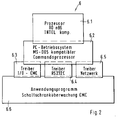
- the central control device 6 built on the main board is based advantageous on a system with components 6.1 to 6.6 of a personal computer (PC), as shown schematically in Fig. 2.
- PC personal computer
- memory chips e.g. an Eprom or EEprom
- the PC components 6.1 to 6.6. allow easy operation when programming the desired Control processes and settings.
- a PC-specific central processor 6.1 contains a in a known manner Micro program for the initial charge from a read-only memory. After the first charge takes over the operating system provided in an operating system unit 6.2 its function and an established command processor automatically loaded. An application program is created by means of the command processor loaded from an application program area 6.6, which the programmed Monitoring, control and regulation processes and given conditions and set values are taken into account and any necessary data is calculated. For example, due to a specific reaction sequence takes place in the application program, when a signal arrives from a door limit switch 1.2. In this case, a Alarm triggered and / or the air conditioning device 2 switched off or according to a further program on one intended for this case Operation can be reversed. In a similar way, specific control procedures when other sensor signals arrive using the application program be specified.
- the sensors are in particular at one Input / output driver 6.3 and are coupled according to the application program and the operating system, and their Sensor signals evaluated.
- a driver 6.4 for a serial interface can in particular peripheral units can be connected, for example an independent one Personal computer with screen and keyboard for programming the central Control device 6.
- a connection can be made via a network driver 6.5
- An external bus system can be produced, for example, the data of several such control cabinets in a central data processing system evaluate.
- the drivers in standard software form a connection between application program and operating system and reduce the programming effort for coupling and monitoring, control and regulation the installation units and add-on units.
- control cabinet monitoring system enables many monitoring and control functions. For example, a door and trim parts inspection be carried out by several door limit switches 1.2 are looped. If the loop is interrupted, a signal is generated issued, which indicates an open state.
- the door limit switch 1.2 can also be designed as a magnetic contact that consists of a magnet on the movable Part and a read relay on the fixed part.
- a legitimation check can be provided with a coding lock, a magnetic card reader, a chip card reader, a punch card reader, non-contact magnetic card recognition, voice recognition, a portrait recognition and / or a hand or fingerprint recognition.
- Valid Identifiers are stored in a reader and are activated when actuated compared to the input. If the comparison is positive, it becomes a valid one Message via the interface and, if the comparison is negative, an invalid message submitted.
- storing the valid identifiers in the overall monitoring system 10 is input via an interface to a Given evaluation unit and compared there.
- Proximity control can also be provided. With motion detectors an approximation is recognized on the basis of infrared, ultrasound or radar. The Entering near the cabinet can be determined by induction loops. The area around the control cabinet can also be protected with light barriers will. In order to register the approach of a person, foot contacts can be made also laid in mats in front of, next to or behind the control cabinet will. If an approximation has been recognized, the central Control device 6 triggered an acoustic or visual alarm and can also be passed on and logged via an interface.
- the cause can be a smoldering fire in the cable insulation, which usually consists of PVC and triggers a risk of dioxins. Plastic parts or paper can also burn during printer operation.
- the smoke sensor 1.5 or smoke detector detects smoke and soot particles and emits a signal to the central control device 6, which triggers a programmed reaction. It can be provided that the reaction is triggered after a time delay to be defined after one or more checks of the signal of the smoke sensor 1.5. If the signal is no longer present, a false alarm can be assumed. The process is then only logged. If the alarm is valid, the voltage to the installed components must be switched off.
- the central control device 6 can be configured in such a way that the fans are switched off after the alarm, so that the installation room is less smoky. In special cases, suctioning out of the cabinet can be useful. The fans must be switched on for this. Motorized ventilation flaps can be used to close the ventilation openings in the event of an alarm. In special cases, opening may make sense. The door lock is released. Setting a high priority and triggering the alarm via as many outputs as possible can be advisable (collective fault message, network connection, serial or parallel interfaces). The alarm can be integrated into the normal fire alarm systems, whereby a position specification and measures are selected. Automatic fire extinguishing systems in the control cabinet are activated. A water spray system installed in the cabinet is opened.
- a pressurized container with a fire extinguishing agent for example CO 2
- a fire extinguishing agent for example CO 2
- the pressure created in the control cabinet when extinguishing can escape by opening motor-operated flaps or automatically opening flaps, which may be unlocked. Escaping via controlled deformation of the paneling is also possible. Forced ventilation of the control cabinet to the outside can be provided.
- the given via the central control device 6 can be just as varied Functions also for other sensor signals.
- the bidirectional network output or a corresponding connection can also voice and Image data are transmitted. This is e.g. a communication between Network supervisor and network technician possible.
Abstract
Description
Die Erfindung bezieht sich auf einen Schaltschrank mit einer zentralen Steuerungseinrichtung zum Überwachen und Steuern von Einbaueinheiten und/oder Anbaueinheiten des Schaltschranks in vorgebbarer Weise.The invention relates to a control cabinet with a central Control device for monitoring and controlling installation units and / or add-on units of the control cabinet in a specifiable manner.
Bei einem bekannten Schaltschrank, wie er in der DE 33 26 977 C2 angegeben ist, wird z.B. eine Einbau- oder Anbaueinheit in Form einer Klimatisierungsbaugruppe überwacht und gesteuert, insbesondere geregelt. Bei einem derartigen Schaltschrank kann die Klimatisierung nur global für das gesamte Schrankvolumen geregelt werden, und die Abstimmung auf besondere Anforderungen nicht nur hinsichtlich der Klimatisierung, sondern auch hinsichtlich anderer Funktionen des Schaltschranks ist nicht möglich. In a known control cabinet, as specified in DE 33 26 977 C2 is e.g. an installation or add-on unit in the form of an air conditioning assembly monitored and controlled, especially regulated. At a Such a cabinet can only be air-conditioned globally for the whole Cabinet volume can be regulated and tailored to special requirements not only in terms of air conditioning, but also in terms of other functions of the control cabinet are not possible.
Der Erfindung liegt die Aufgabe zugrunde, einen Schaltschrank bereitzustellen, der bei einfacher Programmierbarkeit hinsichtlich Überwachung und Steuerung vielfältige Anpassungsmöglichkeiten an unterschiedliche Einsatzbedingungen bietet, wobei der Aufbau einfach und übersichtlich ist.The invention has for its object to provide a control cabinet, the one with simple programmability in terms of monitoring and control various adaptation options to different operating conditions offers, the structure is simple and clear.
Diese Aufgabe wird mit den Merkmalen des Anspruchs 1 gelöst. Hiernach ist also vorgesehen, daß die zentrale Steuerungseinrichtung Komponenten eines Personalcomputers aufweist, über die sie programmierbar ist und mit denen die Überwachung, Steuerung und/oder Regelung nach vorgebbaren Programmen erfolgt.This object is achieved with the features of claim 1. After that is thus provided that the central control device components of a Has personal computers via which it is programmable and with which the Monitoring, control and / or regulation takes place according to predefinable programs.
Die Informationen von und zu unterschiedlichen Überwachungs- und Steuerungsbaugruppen sind also in einer zentralen Steuerungseinrichtung zusammengeführt, die Komponenten eines Personalcomputers aufweist. Die Zustände der verschiedenen Einbaueinheiten bzw. Anbaueinheiten des Schaltschrankes können individuell, auch in Abhängigkeit voneinander, auf jeweils gegebene Einsatzbedingungen des Schaltschranks abgestimmt werden. Auf diese Weise läßt sich der Schaltschrank sowohl im Innen- als auch im Außenbereich an ganz unterschiedliche Anforderungen auf einfache Weise anpassen, wobei die geforderten Zustände zuverlässig überwacht und eingehalten werden. Mit den Komponenten des Personalcomputers kann Standardsoftware eingesetzt, und standardisierte Schnittstellen können verwendet werden. Die Programmierung muß nicht auf Assemblerebene, sondern kann mit höheren Programmiersprachen erfolgen, so daß sich der Benutzer nicht in eine spezielle Programmiersprache einarbeiten muß. Die Anwenderprogramme können vom Personalcomputer übernommen oder auf diesem entwickelt werden. Für die Ein-/Ausgabe können Bibliothekselemente verwendet werden, die ein einfaches Programmieren ermöglichen. Die Hardware zum Anschluß eines Busses, insbesondere eines I2 C-Busses, kann ebenfalls vom Personalcomputer übernommen werden.The information from and to different monitoring and control assemblies is therefore brought together in a central control device which has components of a personal computer. The states of the various built-in units or add-on units of the control cabinet can be individually adjusted, depending on each other, to the given conditions of use of the control cabinet. In this way, the control cabinet can be easily adapted to very different requirements both inside and outside, the required conditions being reliably monitored and maintained. Standard software can be used with the components of the personal computer and standardized interfaces can be used. Programming does not have to be at assembly level, but can be done with higher programming languages so that the user does not have to familiarize himself with a special programming language. The user programs can be adopted from the personal computer or developed on this. Library elements can be used for the input / output, which enable simple programming. The hardware for connecting a bus, in particular an I 2 C bus, can also be taken over by the personal computer.
Ein vorteilhafter Aufbau der zentralen Steuerungseinrichtung besteht darin, daß die Komponenten einen personalcomputer-typischen Mikroprozessor, ein Personalcomputer-Standardbetriebssystem und einen mit diesem kompatiblen Kommandoprozessor sowie Treibereinheiten umfassen. Diese Komponenten können auf einer Hauptplatine angeordnet sein und beanspruchen wenig Platz. Da die Steuerungsfunktionen automatisch ablaufen, wenn sie einmal programmiert sind, erübrigt sich die Installation einer Bildschirmanzeige und Tastatur. Ist eine weitere Programmierung erforderlich, so kann dies einfach dadurch geschehen, daß über eine Treibereinheit und eine entsprechende Schnittstelle vorübergehend ein selbständiger Personalcomputer oder dgl. angeschlossen wird.An advantageous structure of the central control device is that the components a personal computer-typical microprocessor, a personal computer standard operating system and one compatible with this command processor as well as driver units. These components can be arranged on a motherboard and take up little space. Since the Control functions run automatically once they are programmed there is no need to install a display and keyboard. Is a further programming required, this can be done simply by that temporarily via a driver unit and an appropriate interface an independent personal computer or the like is connected.
Zur Erleichterung der Programmierung ist weiterhin vorgesehen, daß die Steuerungseinrichtung einen Anwendungsprogrammteil aufweist, mit dem die Überwachungs-, Steuerungs- und/oder Regelungsdaten bestimmbar, d.h. vorgebbar und/oder berechenbar, sind.To facilitate programming, it is also provided that the Control device has an application program part with which the Monitoring, control and / or regulation data can be determined, i.e. can be specified and / or calculated.
Für eine vielseitige, standardisierte Verbindung mit den Überwachungs- und/oder Steuerungsbaugruppen sind die Maßnahmen vorteilhaft, daß die Treibereinheiten einen Ein-/Ausgabe-Treiber, über den Sensoren abfragbar sind, einen Treiber für eine serielle Schnittstelle, über den Peripheriegeräte einschließlich eines selbständigen Personalcomputers ankoppelbar sind, und einen Netzwerk-Treiber aufweisen, über den die Steuereinrichtung an einen Daten-BUS anschließbar ist. For a versatile, standardized connection with the monitoring and / or Control modules are the measures advantageous that the driver units an input / output driver via which sensors can be queried, a driver for a serial interface, above the peripheral devices including an independent personal computer can be coupled, and have a network driver, via which the control device to a Data bus can be connected.
Weiterhin kann vorgesehen sein, daß die Überwachungsbaugruppen eine Sensoreinrichtung mit wahlweise mindestens einem Feuchtesensor, einem Türendschalter, einem Temperaturfühler, einem Vibrationssensor, einem Rauchsensor, einem Strom-Meßwandler, einem Spannungs-Meßwandler, einem Kunden-Temperaturfühler, einem Code-Schloß und/oder einem Kartenleser aufweisen. Damit können verschiedenartige Informationen bezüglich unterschiedlicher Betriebszustände und Sicherheitsmaßnahmen gewonnen und ausgewertet werden. Dabei ist die Signalweitergabe und Verarbeitung einfach ausgeführt, wenn vorgesehen ist, daß die Sensoreinrichtung über eine Eingangsschnittstelle mit der zentralen Steuerungseinrichtung in bidirektionaler Verbindung steht.Furthermore, it can be provided that the monitoring modules include a sensor device with optionally at least one humidity sensor, a door limit switch, a temperature sensor, a vibration sensor, a smoke sensor, a current transducer, a voltage transducer, a customer temperature sensor, have a code lock and / or a card reader. This allows different types of information regarding different Operating conditions and safety measures obtained and evaluated will. The signal transmission and processing is simple executed if it is provided that the sensor device via an input interface with the central control device in bidirectional Connection is established.
Die Funktionssicherheit des gesamten Überwachungssystems wird dabei durch die Maßnahmen verbessert, daß die Überwachungsbaugruppen eine Funktionsüberwachung mit einer Spannungsversorgungseinrichtung und einer Betriebswertüberwachung aufweisen, daß bei Ausfall einer Normalversorgung auf eine Notversorgung umgeschaltet wird, um programmierte Notfunktionen aufrecht zu erhalten, und daß die zentrale Steuerungseinrichtung separat gepuffert ist.The functional reliability of the entire monitoring system is ensured by the measures improved that the monitoring modules a function monitoring with a voltage supply device and an operating value monitor have that on failure of a normal supply Emergency supply is switched to maintain programmed emergency functions obtained, and that the central control device is buffered separately.
Das Klimatisierungssystem ist einfach und hinsichtlich der Steuerung und Regelung übersichtlich organisiert durch die Maßnahmen, daß die Steuerungsbaugruppen eine Regelungs- und Steuerungsschnittstelle aufweisen, die einerseits mit der zentralen Steuerungseinrichtung und andererseits mit einer Klimatisierungseinrichtung wahlweise mindestens einen Wärmetauscher, einen Ventilator, ein Kühlgerät, eine Heizung, einen Türmagnet und/oder einen Kunden-Lüfter umfaßt, daß die für die Regelung und Steuerung benötigten Signale in der Regelungs- und Steuerungsschnittstelle generierbar sind und daß die Klimatisierungseinrichtung entsprechend Signalen der zentralen Steuerungseinrichtung ansteuerbar ist.The air conditioning system is simple and in terms of control and regulation clearly organized by the measures that the control modules have a regulation and control interface, on the one hand with the central control device and on the other hand with an air conditioning device optionally at least one heat exchanger, one fan, a cooling device, a heater, a door magnet and / or a customer fan includes that the signals required for regulation and control can be generated in the regulation and control interface and that the air conditioning device corresponding to signals from the central control device is controllable.
Ein Einblick in die Betriebszustände und die Möglichkeit einer diesbezüglichen Ansteuerung entsprechender Ausgabeeinheiten werden dadurch erzielt, daß die Steuerungsbaugruppen eine Ausgabeschnittstelle aufweisen, die einerseits mit der zentralen Steuerungseinrichtung in bidirektionaler Verbindung steht und andererseits mit einer Ausgabeeinrichtung verbunden ist, daß die Ausgabeeinrichtung wahlweise mindestens einen parallelen Ausgang, ein Relais, einen Optokoppler, einen Bussystemausgang, einen Telemetrieausgang, einen Netzwerk-Ausgang, einen PC-Schnittstellenausgang, einen Analogsignalausgang, eine Anzeigeneinrichtung, eine Leuchtdiodenanzeige und/oder eine Symbolanzeigeeinheit mit Symbolanzeigeelementen aufweist und daß in der Ausgabeschnittstele Signale der zentralen Steuerungseinrichtung zum Ansprechen der Ausgabeeinrichtung umformbar sind.An insight into the operating states and the possibility of a related Control of corresponding output units are achieved in that the Control modules have an output interface, on the one hand with the central control device is in a bidirectional connection and on the other hand is connected to an output device that the output device optionally at least one parallel output, one relay, one Optocoupler, a bus system output, a telemetry output, a network output, a PC interface output, an analog signal output, a display device, a light-emitting diode display and / or a symbol display unit with symbol display elements and that in the output interface Signals from the central control device for addressing the Output device are deformable.
Ist vorgesehen, daß mit der zentralen Steuerungseinrichtung, Bedientasten, eine Programmier-, Einstell- und Testeinrichtung und/oder eine Leitstelle bidirektional verbunden sind und daß mit der Programmier-, Einstell- und Testeinrichtung fest eingespeicherte Testprozeduren aufrufbar, bestimmte Programmteile änderbar und/oder kundenspezifische Referenzwerte eingebbar sind, so kann jederzeit auf einfache Weise eine Funktionsprüfung und Anderung von eingestellten Parametern, wie z.B. Temperatureinstellwerten, vorgenommen werden. Auf diese Weise ist auch eine Einstellung auf geänderte Bedingungen leicht möglich.It is provided that with the central control device, control buttons, a Programming, setting and testing device and / or a control center bidirectional are connected and that with the programming, setting and testing facility stored test procedures can be called up, certain program parts can be changed and / or customer-specific reference values can be entered at any time a simple way to perform a function test and change the set parameters, such as. Temperature setting values. To this An adjustment to changed conditions is also easily possible.
Ein übersichtlicher Aufbau wird weiterhin dadurch begünstigt, daß die zentrale Steuerungseinrichtung auf einer Hauptplatine aufgebaut ist und daß alle Einund Ausgänge miteinander verknüpfbar sind. A clear structure is further favored by the fact that the central Control device is built on a motherboard and that all Einund Outputs can be linked together.
Die Erfindung wird nachfolgend anhand eines Ausführungsbeispiels unter Bezugnahme auf die Zeichnungen näher erläutert. Es zeigen:
- Fig. 1
- ein Blockschaltbild einer gesamten Schaltschrank-Überwachungseinrichtung, und
- Fig. 2
- ein Blockschaltbild einer bei dem Überwachungssystem nach Fig. 1 vorgesehenen Steuerungseinrichtung.
- Fig. 1
- a block diagram of an entire cabinet monitoring device, and
- Fig. 2
- a block diagram of a control device provided in the monitoring system of FIG. 1.
Die Fig. 1 zeigt eine Gesamtüberwachungseinrichtung 10 für einen Schaltschrank
mit einer Sensoreinrichtung 1, einer Klimatisierungseinrichtung 2, einer
Kommunikationseinrichtung 3, einer Ausgabeeinrichtung 4, einer Funktionsüberwachung
5 sowie einer zentralen Steuerungseinrichtung 6. Die Sensoreinrichtung
1 ist über eine Eingangsschnittstelle 1.10 mit der zentralen Steuerungseinrichtung
6 verbunden, wobei die Verbindung zwischen der Eingangsschnittstelle
1.10 und der zentralen Steuerungseinrichtung 6 bidirektional
ausgebildet ist. Die Sensoreinrichtung 1 umfaßt einen Feuchtesensor 1.1, einen
Türendschalter 1.2, einen Temperaturfühler 1.3, einen Vibrationssensor 1.4,
einen Rauchsensor 1.5, einen Strom-Meßwandler 1.6, einen Spannungs-Meßwandler
1.7, ein Code-Schloß 1.8 und einen Kartenleser 1.9.1 shows an overall monitoring device 10 for a control cabinet
with a sensor device 1, an air conditioning device 2, one
Communication device 3, an output device 4, a
Diese einzelnen Komponenten der Sensoreinrichtung 1 sind beispielhaft angegeben
und können teilweise auch fehlen oder mehrfach vorhanden sein, je nach
Einsatzbedingungen und Kundenwunsch. Dazu kann der Aufbau so sein, daß
ein Austausch oder eine Ergänzung leicht möglich ist. Die Eingangsschnittstelle
1.10 ist vorzugsweise auf einer Platine aufgebaut und stellt auf der einen Seite
eine Spannungsversorgung für die Sensoreinrichtung 1 entsprechend den Anforderungen
der einzelnen Komponenten sicher, wobei Gleich- und Wechselspannungen
bereitgestellt werden können, und verarbeitet auf der anderen Seite die
von den einzelnen Komponenten der Sensoreinrichtung 1 gelieferten Signale
und formt sie so um, daß sie an die zentrale Steuerungseinrichtung 6 weitergeleitet
werden können. Es kann zudem eine Bewertung und Gewichtung der
Signale sowie eine logische Verknüpfung durchgeführt werden.These individual components of the sensor device 1 are given as examples
and can sometimes be missing or multiple, depending on
Conditions of use and customer requirements. For this purpose, the structure can be such that
an exchange or an addition is easily possible. The input interface
1.10 is preferably built on a circuit board and on one side
a voltage supply for the sensor device 1 according to the requirements
of the individual components safely, with direct and alternating voltages
can be provided, and on the other hand processes the
signals supplied by the individual components of the sensor device 1
and reshapes it so that it is forwarded to the
Die Klimatisierungseinrichtung 2 weist gemäß dem Ausführungsbeispiel einen
Wärmetauscher 2.1, einen Ventilator 2.2, ein Kühlgerät 2.3, eine Heizung 2.4,
einen Türmagnet 2.5 und eine Regelungs- und Steuerungsschnittstelle 2.6 auf.
Die Regelungs- und Steuerschnittstelle 2.6 steht einerseits mit der zentralen
Steuerungseinrichtung 6 und andererseits mit den genannten Komponeten der
Klimatisierungseinrichtung 2 jeweils in bidirektionaler Verbindung. Mit Hilfe der
Regelungs- und Steuerungsschnittstelle 2.6 werden die angeschlossenen Komponenten
der Klimatisierungseinrichtung 2 entsprechend den Signalen der
zentralen Steuerungseinrichtung 6 angesteuert. Infolge der bidirektionalen
Verbindung besteht neben der Steuerung bzw. Regelung auch die Möglichkeit
der Funktionsüberwachung der Klimatisierungseinrichtung 2 mit ihren einzelnen
Komponenten. In der Regelungs- und Steuerungsschnittstelle 2.6 können alle
für die Ansteuerung benötigen Signale selbst generiert werden, so daß der
Anschluß an die zentrale Steuerungseinrichtung 6 einfach und übersichtlich ist.
Der Ventilator 2.2 und ein evtl. Kunden-Lüfter können Wechselspannungs- oder
Gleichspannungs-Versionen sein. Die Klimatisierungseinrichtung 2 umfaßt vorteilhafterweise
auch Kompressoren, pneumatische oder hydraulische Ventile,
Be- und Entfeuchtungseinrichtungen, Drucksensoren und Luftströmungsüberwachungseinrichtungen.
Die einzelnen Komponenten der Klimatisierungseinrichtung
2 können nach dem jeweiligen Bedarf vorhanden sein, angesteuert und
geregelt werden. According to the exemplary embodiment, the air conditioning device 2 has one
Heat exchanger 2.1, a fan 2.2, a cooling device 2.3, a heater 2.4,
a door magnet 2.5 and a regulation and control interface 2.6.
The regulation and control interface 2.6 is on the one hand with the
Die Kommunikationseinrichtung 3 umfaßt Bedientasten 3.1 und eine Programmier-, Einstell- und Testeinrichtung 3.2 sowie evtl. eine Leitstelle. Die Programmier-, Einstell- und Testeinrichtung 3.2 kann beispielsweise über ein (nicht gezeigtes) Handmodul bedient werden. Mit der Programmier-, Einstell- und Testeinrichtung 3.2 können sowohl fest eingespeicherte Testprozeduren aufgerufen werden, als auch bestimmte Programmteile geändert werden (z.B. nachträgliches Ändern von Temperatureinstellwerten). Weiterhin können kundenseitige Referenzwerte (z.B. für die Kalibrierung) eingegeben werden. Über die Leitstelle können Betriebszustände vom Überwachungspersonal kontrolliert und gegebenenfalls eingestellt werden.The communication device 3 comprises control buttons 3.1 and a programming, Adjustment and test equipment 3.2 and possibly a control center. The Programming, setting and testing device 3.2 can, for example, via a Hand module (not shown) can be operated. With the programming, setting and Test facility 3.2 can both permanently stored test procedures be called when certain program parts are changed (e.g. subsequent change of temperature setting values). Furthermore, customer side Reference values (e.g. for calibration) can be entered. over the control center can control the operating status of the monitoring personnel and be adjusted if necessary.
Die Ausgabeeinrichtung 4 umfaßt einen Parallel-Ausgang 4.1, einen Optokoppler
und/oder Relais 4.2, einen Bussystemausgang 4.3, einen Telemetrieausgang
4.4, einen Netzwerk-Ausgang 4.5, einen PC-Schnittstellenausgang 4.6, evtl.
einen Analogsignalausgang, eine Anzeigeeinrichtung 4.7, eine Leuchtdiodenanzeige
4.8, eine Symbolanzeigeeinheit mit Symbolanzeigeelementen 4.9 sowie
eine Ausgabeschnittstelle 4.10. Die Ausgabeschnittstelle 4.10 steht in bidirektionaler
Verbindung mit der zentralen Steuerungseinrichtung 6. Mit Hilfe
der Ausgabeabschnittstelle 4.10 können Informationssignale in verschiedenster
Form ausgegeben werden, wie die verschiedenen Komponenten der Ausgabeeinrichtung
4 erkennen lassen. Beispielsweise können über den Telemetrieausgang
4.4 Daten an eine entfernte Überwachungsstation übermittelt werden.
Über das Relais 4.2 oder den Optokoppler 4.2 können z.B. externe Meldeeinrichtungen
angesprochen werden, die z.B. auf eine Funktionsstörung oder einen
unberechtigten Eingriff hinweisen. Der Bussystemausgang 4.3 kann z.B. einen
Feldbus oder dgl. umfassen. Der PC-Schnittstellenausgang 4.6 kann z.B. als RS
232-Schnittstelle oder dgl. ausgebildet sein. Als Anzeigeeinrichtung 4.7 können
auch andere geeignete Anzeigeeinheiten, z.B. LCD-Einheiten oder ähnliche, vorgesehen
sein. Der Analogsignalausgang kann als Spannungs- oder Stromausgang
ausgeführt sein.The output device 4 comprises a parallel output 4.1, an optocoupler
and / or relay 4.2, a bus system output 4.3, a telemetry output
4.4, a network output 4.5, a PC interface output 4.6, possibly
an analog signal output, a display device 4.7, a light-emitting diode display
4.8, a symbol display unit with symbol display elements 4.9 and
an output interface 4.10. The output interface 4.10 is bidirectional
Connection to the
Die Funktionsüberwachung beinhaltet eine Notversorgung 5.1, eine Normalversorgung
5.2 sowie eine Betriebswerteüberwachung 5.3. Die Notversorgung 5.1
stellt z.B. eine batteriegepufferte Spannungsversorgung für die Gesamtüberwachungseinrichtung
10 dar, die im Falle eines Netzausfalls bestimmte programmierte
Notfunktionen bei Spannungsausfall aufrecht erhält. Die Normalversorgung
5.2, insbesondere Netz-Spannungsversorgung, wird ständig überwacht,
um im Notfall direkt auf die Notversorgung 5.1 umzuschalten. Die
zentrale Steuerungseinrichtung 6, die vorzugsweise auf einer Hauptplatine
aufgebaut ist, ist noch einmal separat gepuffert.The function monitoring includes an emergency supply 5.1, a normal supply
5.2 and monitoring of operating values 5.3. Emergency care 5.1
e.g. a battery-backed power supply for the overall monitoring device
10 which programmed certain in the event of a power failure
Maintains emergency functions in the event of a power failure. The normal care
5.2, especially mains voltage supply, is constantly monitored,
to switch directly to emergency care 5.1 in an emergency. The
Die Betriebsüberwachung 5.3 dient sowohl als Speicher für eine Betriebsdatenerfassung (z.B. Laufzeiten), als auch als Fehlerspeicher für im Betrieb aufgetretene Fehler oder Störungen, die sich selbst zurückgesetzt haben.The operational monitoring 5.3 serves both as a memory for an operational data acquisition (e.g. run times), as well as an error memory for in operation errors or faults that have occurred that have reset themselves.
Außer den beispielhaft genannten einzelnen Komponenten, der verschiedenen
Einrichtungen der Gesamtüberwachungseinrichtung 10 können, soweit zweckmäßig,
weitere oder andere Komponenten vorgesehen werden. Dabei ist der
Anschluß an das jeweilige Interface bzw. die Verbindung mit der zentralen
Steuerungseinrichtung 6 einfach möglich und die Anpassung durch entsprechende
einfache Umprogrammierung der zentralen Steuerungseinrichtung 6
ebenfalls leicht durchführbar.In addition to the individual components mentioned by way of example, the various
Devices of the overall monitoring device 10 can, if appropriate,
additional or different components can be provided. Here is the
Connection to the respective interface or the connection to the central one
Die auf der Hauptplatine aufgebaute zentrale Steuerungseinrichtung 6 basiert
vorteilhaft auf einem System mit Komponenten 6.1 bis 6.6 eines Personalcomputers
(PC), wie in Fig. 2 schematisch dargestellt. Mit Hilfe von Speicherbausteinen,
z.B. eines Eproms oder EEproms, ist die Gesamtüberwachungseinrichtung
10 in der Lage, alle Ein- und Ausgänge beliebig miteinander zu
verknüpfen, so daß ohne aufwendige bauliche Änderungen sehr unterschiedliche
Anpassungsmöglichkeiten gegeben sind. Die PC-Komponenten 6.1 bis 6.6.
ermöglichen eine einfache Bedienung beim Programmieren der gewünschten
Steuerungsabläufe und Einstellungen.The
Ein PC-spezifischer Zentralprozessor 6.1 enthält in bekannter Weise ein Mikroprogramm für die Urladung aus einem Festwertspeicher. Nach der Urladung übernimmt das in einer Betriebssystemeinheit 6.2 vorgesehene Betriebssystem seine Funktion und ein eingerichteter Kommandoprozessor wird automatisch geladen. Mittels des Kommandoprozessors wird ein Anwendungsprogramm aus einem Anwendungsprogrammbereich 6.6 geladen, das die programmierten Überwachungs-, Steuerungs- und Regelungsabläufe vorgibt und dabei vorgegebene Bedingungen sowie eingestellte Werte berücksichtigt und gegebenenfalls noch erforderliche Daten errechnet. Beispielsweise kann aufgrund des Anwendungsprogramms ein spezifischer Reaktionsablauf erfolgen, wenn von einem Türendschalter 1.2 ein Signal eintrifft. In diesem Fall kann ein Alarm ausgelöst und/oder die Klimatisierungseinrichtung 2 abgeschaltet oder entsprechend einem weiteren Programm auf einen für diesen Fall vorgesehenen Betrieb umgesteuert werden. Auf ähnliche Weise können spezifische Steuerungsabläufe bei Eintreffen anderer Sensorsignale mittels des Anwendungsprogramms vorgegeben werden. Die Sensoren sind dabei insbesondere an einen Ein-/Ausgabe-Treiber 6.3 gekoppelt und werden nach Maßgabe des Anwendungsprogramms und des Betriebssystems abgefragt, und hinsichtlich ihrer Sensorsignale ausgewertet. A PC-specific central processor 6.1 contains a in a known manner Micro program for the initial charge from a read-only memory. After the first charge takes over the operating system provided in an operating system unit 6.2 its function and an established command processor automatically loaded. An application program is created by means of the command processor loaded from an application program area 6.6, which the programmed Monitoring, control and regulation processes and given conditions and set values are taken into account and any necessary data is calculated. For example, due to a specific reaction sequence takes place in the application program, when a signal arrives from a door limit switch 1.2. In this case, a Alarm triggered and / or the air conditioning device 2 switched off or according to a further program on one intended for this case Operation can be reversed. In a similar way, specific control procedures when other sensor signals arrive using the application program be specified. The sensors are in particular at one Input / output driver 6.3 and are coupled according to the application program and the operating system, and their Sensor signals evaluated.
Über einen Treiber 6.4 für eine serielle Schnittstelle können insbesondere
periphere Einheiten angeschlossen werden, beispielsweise ein selbständiger
Personalcomputer mit Bildschirm und Tastatur zum Programmieren der zentralen
Steuerungseinrichtung 6. Über einen Netzwerktreiber 6.5 kann ein Anschluß an
ein externes Bussystem hergestellt werden, um beispielsweise die Daten mehrerer
derartiger Schaltschränke in einer zentralen Datenverarbeitungsanlage
auszuwerten.A driver 6.4 for a serial interface can in particular
peripheral units can be connected, for example an independent one
Personal computer with screen and keyboard for programming the
Die in einer Standardsoftware bestehenden Treiber bilden eine Verbindung zwischen Anwendungsprogramm und Betriebssystem und verringern den Programmieraufwand zur Ankopplung und Überwachung, Steuerung und Regelung der Einbaueinheiten und Anbaueinheiten wesentlich.The drivers in standard software form a connection between application program and operating system and reduce the programming effort for coupling and monitoring, control and regulation the installation units and add-on units.
Das Schaltschranküberwachungssystem ermöglicht auf diese Weise viele Überwachungs- und Steuerungsfunktionen. Beispielsweise kann eine Tür- und Verkleidungsteilekontrolle durchgeführt werden, indem mehrere Türendschalter 1.2 in einer Schleife geschaltet sind. Bei Unterbrechung der Schleife wird ein Signal abgegeben, das einen Öffnungszustand angibt. Der Türendschalter 1.2 kann auch als Magnetkontakt ausgebildet sein, der aus einem Magnet am beweglichen Teil und einem Readrelais am festen Teil besteht.In this way, the control cabinet monitoring system enables many monitoring and control functions. For example, a door and trim parts inspection be carried out by several door limit switches 1.2 are looped. If the loop is interrupted, a signal is generated issued, which indicates an open state. The door limit switch 1.2 can also be designed as a magnetic contact that consists of a magnet on the movable Part and a read relay on the fixed part.
Weiterhin kann eine Legitimierungskontrolle vorgesehen sein mit einem Codierschloß, einem Magnetkartenleser, einem Chipkartenleser, einem Lochkartenleser, einer berührungslosen Magnetkartenerkennung, einer Stimmenerkennung, einer Porträterkennung und/oder einer Hand- oder Fingerabdruckerkennung. Gültige Kennungen sind in einem Lesegerät eingespeichert und werden bei Betätigung mit der Eingabe verglichen. Bei positivem Vergleich wird eine gültige Meldung über die Schnittstelle und bei negativem Vergleich eine Ungültig-Meldung abgegeben. Bei Speicherung der gültigen Kennungen in dem Gesamtüberwachungssystem 10 wird die Eingabe über eine Schnittstelle an eine Auswerteeinheit gegeben und dort verglichen.Furthermore, a legitimation check can be provided with a coding lock, a magnetic card reader, a chip card reader, a punch card reader, non-contact magnetic card recognition, voice recognition, a portrait recognition and / or a hand or fingerprint recognition. Valid Identifiers are stored in a reader and are activated when actuated compared to the input. If the comparison is positive, it becomes a valid one Message via the interface and, if the comparison is negative, an invalid message submitted. When storing the valid identifiers in the overall monitoring system 10 is input via an interface to a Given evaluation unit and compared there.
Auch eine Näherungskontrolle kann vorgesehen sein. Durch Bewegungsmelder
auf Infrarot-, Ultraschall- oder Radarbasis wird eine Annäherung erkannt. Das
Betreten in Schranknähe kann durch Induktionsschleifen festgestellt werden.
Mit Lichtschranken kann der Bereich um den Schaltschrank ebenfalls abgesichert
werden. Um die Annäherung einer Person zu registrieren, können Trittkontakte
auch in Matten vor, neben oder hinter dem Schaltschrank verlegt
werden. Wenn eine Annäherung erkannt worden ist, kann mittels der zentralen
Steuerungseinrichtung 6 ein akustischer oder optischer Alarm ausgelöst und
auch über eine Schnittstelle weitergegeben und protokolliert werden.Proximity control can also be provided. With motion detectors
an approximation is recognized on the basis of infrared, ultrasound or radar. The
Entering near the cabinet can be determined by induction loops.
The area around the control cabinet can also be protected with light barriers
will. In order to register the approach of a person, foot contacts can be made
also laid in mats in front of, next to or behind the control cabinet
will. If an approximation has been recognized, the
Bei Ansprechen des Rauchsensors infolge einer "Verrauchung" des Schrankinnenraums
kann Ursache ein Schwelbrand einer Kabelisolierung sein, die meist
aus PVC besteht und eine Dioxingefahr auslöst. Ferner können Kunststoffteile
oder Papier bei Druckerbetrieb brennen. Der Rauchsensor 1.5 bzw. Rauchmelder
erfaßt Rauch- und Rußpartikel und gibt ein Signal an die zentrale Steuerungseinrichtung
6 ab, die eine programmierte Reaktion auslöst. Dabei kann vorgesehen
sein, daß die Reaktion nach einer zu definierenden Zeitverzögerung nach
einer oder mehreren Kontrollen des Signals des Rauchsensors 1.5 ausgelöst
wird. Steht das Signal nicht mehr an, kann von einem Fehlalarm ausgegangen
werden. Der Vorgang wird dann nur protokolliert. Bei gültigem Alarm ist die
Spannung zu den installierten Bauteilen abzuschalten. Die zentrale Steuerungseinrichtung
6 kann so konfiguriert sein, daß nach dem Alarm die Ventilatoren
abgeschaltet werden, so daß der Aufstellraum weniger verqualmt. In
Sonderfällen kann ein Absaugen aus dem Schrank sinnvoll sein. Die
Ventilatoren sind hierzu einzuschalten. Durch motorisch betriebene Lüftungsklappen
können im Alarmfall die Lüftungsöffnungen verschlossen werden.
In Sonderfällen kann ein Öffnen sinnvoll sein. Die Türverriegelung wird aufgehoben.
Das Setzen einer hohen Priorität und die Auslösung des Alarms über
möglichst viele Ausgänge kann zweckmäßig sein (Sammelstörmeldung, Netzanschluß,
serielle oder parallele Schnittstellen). Der Alarm kann in die normalen
Feueralarmierungssysteme eingebunden werden, wobei eine Positionsangabe
und Maßnahmenauswahl erfolgt. Automatische Feuerlöschsysteme im Schaltschrank
werden aktiv geschaltet. Dabei wird eine im Schrank installierte
Wassersprühanlage geöffnet. Ein unter Druck stehender Behälter mit einem
Feuerlöschmittel, z.B. CO2, wird geöffnet, und das Feuerlöschmittel kann über
vorgesehene Öffnungen in den Schrank strömen. Der beim Löschen enstehende
Druck im Schaltschrank kann durch Öffnen motorisch betriebener Klappen oder
selbsttätig öffnender Klappen, die evtl. entriegelt werden, entweichen. Ein
Entweichen über kontrolliert sich verformende Beplankungsteile ist ebenfalls
möglich. Eine Zwangsentlüftung des Schaltschranks nach außen kann vorgesehen
sein.If the smoke sensor responds as a result of "smoke" in the interior of the cabinet, the cause can be a smoldering fire in the cable insulation, which usually consists of PVC and triggers a risk of dioxins. Plastic parts or paper can also burn during printer operation. The smoke sensor 1.5 or smoke detector detects smoke and soot particles and emits a signal to the
Ähnlich vielfältig können die über die zentrale Steuerungseinrichtung 6 gegebenen
Funktionen auch für andere Sensorsignale sein.The given via the
Über den bidirektionalen Bussystemausgang 4.3, den bidirektionalen Netzwerkausgang bzw. einen entsprechenden Anschluß können auch Sprach- und Bilddaten übertragen werden. Damit ist z.B. eine Kommunikation zwischen Netz-Supervisor und Netz-Techniker möglich.Via the bidirectional bus system output 4.3, the bidirectional network output or a corresponding connection can also voice and Image data are transmitted. This is e.g. a communication between Network supervisor and network technician possible.
Claims (12)
dadurch gekennzeichnet,
characterized,
dadurch gekennzeichnet,
characterized,
dadurch gekennzeichnet,
characterized,
dadurch gekennzeichnet,
characterized,
dadurch gekennzeichnet,
characterized,
dadurch gekennzeichnet,
characterized,
dadurch gekennzeichnet,
characterized,
dadurch gekennzeichnet,
characterized,
dadurch gekennzeichnet,
characterized,
dadurch gekennzeichnet,
characterized,
dadurch gekennzeichnet,
characterized,
Applications Claiming Priority (2)
| Application Number | Priority Date | Filing Date | Title |
|---|---|---|---|
| DE19710019 | 1997-03-12 | ||
| DE19710019A DE19710019C2 (en) | 1996-03-13 | 1997-03-12 | Control cabinet with a central control device for monitoring, controlling and / or regulating installation and / or add-on units |
Publications (2)
| Publication Number | Publication Date |
|---|---|
| EP0864951A1 true EP0864951A1 (en) | 1998-09-16 |
| EP0864951B1 EP0864951B1 (en) | 2001-06-13 |
Family
ID=7822991
Family Applications (1)
| Application Number | Title | Priority Date | Filing Date |
|---|---|---|---|
| EP98200489A Expired - Lifetime EP0864951B1 (en) | 1997-03-12 | 1998-02-13 | Switchgear cabinet with a central control system for monitoring and control of integrated and/or separate units |
Country Status (4)
| Country | Link |
|---|---|
| US (1) | US6222448B1 (en) |
| EP (1) | EP0864951B1 (en) |
| JP (1) | JP3142812B2 (en) |
| ES (1) | ES2159168T3 (en) |
Cited By (1)
| Publication number | Priority date | Publication date | Assignee | Title |
|---|---|---|---|---|
| CN102183949A (en) * | 2011-02-28 | 2011-09-14 | 中国北方车辆研究所 | Method for realization of optimally-cascaded multiplex intelligent simulation load |
Families Citing this family (36)
| Publication number | Priority date | Publication date | Assignee | Title |
|---|---|---|---|---|
| DE19609689B4 (en) * | 1996-03-13 | 2006-01-26 | Rittal Gmbh & Co. Kg | Control cabinet with a central control device for monitoring, controlling and / or regulating installation and / or add-on units |
| DE19911310A1 (en) * | 1999-03-13 | 2000-09-21 | Loh Kg Rittal Werk | Device for monitoring a switch cabinet includes a basic input/output device fitted with monitoring and controlling function cards and a power supply device. |
| DE19911320A1 (en) * | 1999-03-13 | 2000-09-21 | Loh Kg Rittal Werk | Monitoring device for switch box with operation restricted to monitoring of preset threshold values |
| DE19911824C2 (en) * | 1999-03-17 | 2001-12-20 | Loh Kg Rittal Werk | Control cabinet monitoring system |
| KR19990083691A (en) * | 1999-05-28 | 1999-12-06 | 김원선 | A perm an ency temperature and humidity micom cotroller |
| DE19933086B4 (en) * | 1999-07-15 | 2008-11-20 | Robert Bosch Gmbh | Method and device for mutual monitoring of control units |
| US6866581B2 (en) * | 1999-09-24 | 2005-03-15 | Igt | Video gaming apparatus for wagering with universal computerized controller and I/O interface for unique architecture |
| US6935946B2 (en) * | 1999-09-24 | 2005-08-30 | Igt | Video gaming apparatus for wagering with universal computerized controller and I/O interface for unique architecture |
| DE10007270A1 (en) * | 2000-02-17 | 2001-11-29 | Loh Kg Rittal Werk | Control cabinet air conditioning |
| US7043641B1 (en) * | 2000-03-08 | 2006-05-09 | Igt | Encryption in a secure computerized gaming system |
| CA2402389A1 (en) * | 2000-03-08 | 2002-09-19 | Shuffle Master, Inc. | Computerized gaming system, method and apparatus |
| US7988559B2 (en) * | 2001-03-08 | 2011-08-02 | Igt | Computerized gaming system, method and apparatus |
| DE10042165C1 (en) * | 2000-08-17 | 2002-04-18 | Butzke Werke Aqua | System for controlling and monitoring sanitary fittings |
| DE10108599C2 (en) * | 2001-02-22 | 2003-04-30 | Rittal Gmbh & Co Kg | Control cabinet or control cabinet arrangement with a monitoring device arranged therein |
| US7203841B2 (en) * | 2001-03-08 | 2007-04-10 | Igt | Encryption in a secure computerized gaming system |
| DE10113627B4 (en) * | 2001-03-20 | 2005-12-29 | Rittal Gmbh & Co. Kg | Cabinet monitoring device |
| DE10113626A1 (en) * | 2001-03-20 | 2002-10-02 | Rittal Gmbh & Co Kg | Control cabinet or control cabinet arrangement with a monitoring device arranged therein |
| DE10119637A1 (en) * | 2001-04-20 | 2002-11-21 | Rittal Gmbh & Co Kg | Cabinet monitoring system |
| CA2460046C (en) * | 2001-09-10 | 2014-06-10 | Igt | Method for developing gaming programs compatible with a computerized gaming operating system and apparatus |
| US7931533B2 (en) * | 2001-09-28 | 2011-04-26 | Igt | Game development architecture that decouples the game logic from the graphics logics |
| US6902481B2 (en) | 2001-09-28 | 2005-06-07 | Igt | Decoupling of the graphical presentation of a game from the presentation logic |
| US8708828B2 (en) | 2001-09-28 | 2014-04-29 | Igt | Pluggable modular gaming modifiers and configuration templates for gaming environments |
| US7340311B2 (en) * | 2002-03-19 | 2008-03-04 | Richard Landis | Electrical panel access and control apparatus including true emergency stop and power buss lockout |
| US20030203755A1 (en) * | 2002-04-25 | 2003-10-30 | Shuffle Master, Inc. | Encryption in a secure computerized gaming system |
| WO2004068614A2 (en) * | 2003-01-24 | 2004-08-12 | Tecumseh Products Company | Integrated hvacr control and protection system |
| US7623028B2 (en) | 2004-05-27 | 2009-11-24 | Lawrence Kates | System and method for high-sensitivity sensor |
| DE102005002314A1 (en) * | 2005-01-17 | 2006-07-27 | Rittal Gmbh & Co. Kg | Control cabinet control and monitoring system |
| DE102008012097B4 (en) * | 2008-02-29 | 2013-02-28 | Rittal Gmbh & Co. Kg | Monitoring device for the operation of control cabinet devices |
| US8184014B2 (en) | 2008-06-27 | 2012-05-22 | Schlumberger Technology Corporation | Driver to transmit signals over a transmission line in a well |
| EP2452415B1 (en) | 2009-07-08 | 2015-09-02 | ABB Research Ltd. | Bus condition monitoring system |
| US8463453B2 (en) | 2009-11-13 | 2013-06-11 | Leviton Manufacturing Co., Inc. | Intelligent metering demand response |
| US8755944B2 (en) * | 2009-11-13 | 2014-06-17 | Leviton Manufacturing Co., Inc. | Electrical switching module |
| AT511971B1 (en) * | 2011-10-05 | 2016-02-15 | Fronius Int Gmbh | METHOD FOR MONITORING A COOLING OR HEATING DEVICE AND MONITORING DEVICE THEREFOR |
| CN102967329A (en) * | 2012-11-08 | 2013-03-13 | 大连东方电器制造有限公司 | Switch cabinet monitoring alarming device |
| JP6489742B2 (en) * | 2014-01-30 | 2019-03-27 | 三菱重工業株式会社 | Air conditioning system and control method thereof |
| CN106249712A (en) * | 2016-08-19 | 2016-12-21 | 广东锐捷安全技术股份有限公司 | A kind of intelligent cluster controlled platform |
Citations (4)
| Publication number | Priority date | Publication date | Assignee | Title |
|---|---|---|---|---|
| DE3326977A1 (en) * | 1983-07-27 | 1985-02-07 | Bruno 7441 Wolfschlugen Kümmerle | Cooling set for electrical switch cabinets |
| US4567557A (en) * | 1983-02-23 | 1986-01-28 | Burns Martin J | Building intelligence system |
| EP0192108A2 (en) * | 1985-02-11 | 1986-08-27 | Rodger T. Lovrenich | Control station |
| US5317501A (en) * | 1987-10-13 | 1994-05-31 | Bernhard Hilpert | Control system for a numerically controlled machine |
Family Cites Families (1)
| Publication number | Priority date | Publication date | Assignee | Title |
|---|---|---|---|---|
| US5400246A (en) * | 1989-05-09 | 1995-03-21 | Ansan Industries, Ltd. | Peripheral data acquisition, monitor, and adaptive control system via personal computer |
-
1998
- 1998-02-13 EP EP98200489A patent/EP0864951B1/en not_active Expired - Lifetime
- 1998-02-13 ES ES98200489T patent/ES2159168T3/en not_active Expired - Lifetime
- 1998-03-10 US US09/037,651 patent/US6222448B1/en not_active Expired - Fee Related
- 1998-03-11 JP JP10059536A patent/JP3142812B2/en not_active Expired - Fee Related
Patent Citations (4)
| Publication number | Priority date | Publication date | Assignee | Title |
|---|---|---|---|---|
| US4567557A (en) * | 1983-02-23 | 1986-01-28 | Burns Martin J | Building intelligence system |
| DE3326977A1 (en) * | 1983-07-27 | 1985-02-07 | Bruno 7441 Wolfschlugen Kümmerle | Cooling set for electrical switch cabinets |
| EP0192108A2 (en) * | 1985-02-11 | 1986-08-27 | Rodger T. Lovrenich | Control station |
| US5317501A (en) * | 1987-10-13 | 1994-05-31 | Bernhard Hilpert | Control system for a numerically controlled machine |
Non-Patent Citations (1)
| Title |
|---|
| "PCS AND SMART I/O INVADE PLC TERRITORY", I & CS - INDUSTRIAL AND PROCESS CONTROL MAGAZINE, vol. 68, no. 5, 1 May 1995 (1995-05-01), pages 53 - 56, XP000508356 * |
Cited By (2)
| Publication number | Priority date | Publication date | Assignee | Title |
|---|---|---|---|---|
| CN102183949A (en) * | 2011-02-28 | 2011-09-14 | 中国北方车辆研究所 | Method for realization of optimally-cascaded multiplex intelligent simulation load |
| CN102183949B (en) * | 2011-02-28 | 2013-02-20 | 中国北方车辆研究所 | Method for realization of optimally-cascaded multiplex intelligent simulation load |
Also Published As
| Publication number | Publication date |
|---|---|
| JP3142812B2 (en) | 2001-03-07 |
| EP0864951B1 (en) | 2001-06-13 |
| US6222448B1 (en) | 2001-04-24 |
| JPH1151451A (en) | 1999-02-26 |
| ES2159168T3 (en) | 2001-09-16 |
Similar Documents
| Publication | Publication Date | Title |
|---|---|---|
| EP0864951B1 (en) | Switchgear cabinet with a central control system for monitoring and control of integrated and/or separate units | |
| DE19710019C2 (en) | Control cabinet with a central control device for monitoring, controlling and / or regulating installation and / or add-on units | |
| EP0886898B1 (en) | Control box with a device for monitoring and controlling built-in and/or fitted components | |
| DE3803892C2 (en) | ||
| DE102004013601A1 (en) | Mobile barrier operating procedure and device | |
| DE3490205C2 (en) | ||
| WO2006074808A1 (en) | Switchgear cabinet control system and monitoring system | |
| WO2007076939A2 (en) | Apparatus for controlling at least one machine | |
| DE19714838C2 (en) | Cabinet air-conditioning device | |
| EP1065577B1 (en) | Safety device for at least one door, preferably for escape routes | |
| DE102007041383B4 (en) | Smoke and heat extraction and ventilation device comprising smoke and heat extraction and ventilation devices, each with a motor drive | |
| DE102005031112A1 (en) | Operating parameter transmission method for actuating unit for movable barrier and device | |
| EP1374001B1 (en) | Switchgear cabinet or switchgear cabinet assembly comprising a monitoring device that is arranged therein | |
| EP1072743A1 (en) | Escape route device for at least a door or a window in escape routes | |
| DE19607918A1 (en) | Control unit for motorised actuator for door or window system | |
| DE19930690C2 (en) | Situation detection device for blockage detection in doors, gates or the like | |
| DE102007011428B4 (en) | Control unit for a smoke and heat exhaust system of a building | |
| EP1760558B1 (en) | System and method for assessing the safety of a technical system | |
| DE10011763A1 (en) | Locking device for door(s), preferably in escape and rescue routes, has local and central emergency off switches for lock arrangement with separate electrical circuits | |
| WO2003085463A1 (en) | Electric motor-operated drive device comprising an initial fault safety system | |
| DE102020129085A1 (en) | System for safety-related cooling of a control cabinet | |
| DE4244012A1 (en) | Workshop roof with controlled ventilation panel system | |
| DE4445465A1 (en) | Intruder alarm signal evaluation system | |
| EP0866283A2 (en) | Device for monitoring and controlling climatisation elements | |
| DE10207513B4 (en) | Control cabinet monitoring and control cabinet control device |
Legal Events
| Date | Code | Title | Description |
|---|---|---|---|
| PUAI | Public reference made under article 153(3) epc to a published international application that has entered the european phase |
Free format text: ORIGINAL CODE: 0009012 |
|
| 17P | Request for examination filed |
Effective date: 19980716 |
|
| AK | Designated contracting states |
Kind code of ref document: A1 Designated state(s): ES FR GB IT |
|
| AX | Request for extension of the european patent |
Free format text: AL;LT;LV;MK;RO;SI |
|
| AKX | Designation fees paid |
Free format text: ES FR GB IT |
|
| RBV | Designated contracting states (corrected) |
Designated state(s): ES FR GB IT |
|
| REG | Reference to a national code |
Ref country code: DE Ref legal event code: 8566 |
|
| 17Q | First examination report despatched |
Effective date: 19990804 |
|
| GRAG | Despatch of communication of intention to grant |
Free format text: ORIGINAL CODE: EPIDOS AGRA |
|
| GRAG | Despatch of communication of intention to grant |
Free format text: ORIGINAL CODE: EPIDOS AGRA |
|
| GRAH | Despatch of communication of intention to grant a patent |
Free format text: ORIGINAL CODE: EPIDOS IGRA |
|
| GRAH | Despatch of communication of intention to grant a patent |
Free format text: ORIGINAL CODE: EPIDOS IGRA |
|
| GRAA | (expected) grant |
Free format text: ORIGINAL CODE: 0009210 |
|
| AK | Designated contracting states |
Kind code of ref document: B1 Designated state(s): ES FR GB IT |
|
| ITF | It: translation for a ep patent filed |
Owner name: JACOBACCI & PERANI S.P.A. |
|
| REG | Reference to a national code |
Ref country code: ES Ref legal event code: FG2A Ref document number: 2159168 Country of ref document: ES Kind code of ref document: T3 |
|
| GBT | Gb: translation of ep patent filed (gb section 77(6)(a)/1977) |
Effective date: 20010906 |
|
| ET | Fr: translation filed | ||
| REG | Reference to a national code |
Ref country code: GB Ref legal event code: IF02 |
|
| PLBE | No opposition filed within time limit |
Free format text: ORIGINAL CODE: 0009261 |
|
| STAA | Information on the status of an ep patent application or granted ep patent |
Free format text: STATUS: NO OPPOSITION FILED WITHIN TIME LIMIT |
|
| 26N | No opposition filed | ||
| PGFP | Annual fee paid to national office [announced via postgrant information from national office to epo] |
Ref country code: ES Payment date: 20090324 Year of fee payment: 12 |
|
| PGFP | Annual fee paid to national office [announced via postgrant information from national office to epo] |
Ref country code: GB Payment date: 20090227 Year of fee payment: 12 |
|
| PGFP | Annual fee paid to national office [announced via postgrant information from national office to epo] |
Ref country code: IT Payment date: 20090225 Year of fee payment: 12 |
|
| PGFP | Annual fee paid to national office [announced via postgrant information from national office to epo] |
Ref country code: FR Payment date: 20090224 Year of fee payment: 12 |
|
| GBPC | Gb: european patent ceased through non-payment of renewal fee |
Effective date: 20100213 |
|
| REG | Reference to a national code |
Ref country code: FR Ref legal event code: ST Effective date: 20101029 |
|
| PG25 | Lapsed in a contracting state [announced via postgrant information from national office to epo] |
Ref country code: FR Free format text: LAPSE BECAUSE OF NON-PAYMENT OF DUE FEES Effective date: 20100301 |
|
| PG25 | Lapsed in a contracting state [announced via postgrant information from national office to epo] |
Ref country code: GB Free format text: LAPSE BECAUSE OF NON-PAYMENT OF DUE FEES Effective date: 20100213 Ref country code: IT Free format text: LAPSE BECAUSE OF NON-PAYMENT OF DUE FEES Effective date: 20100213 |
|
| REG | Reference to a national code |
Ref country code: ES Ref legal event code: FD2A Effective date: 20110408 |
|
| PG25 | Lapsed in a contracting state [announced via postgrant information from national office to epo] |
Ref country code: ES Free format text: LAPSE BECAUSE OF NON-PAYMENT OF DUE FEES Effective date: 20110324 |
|
| PG25 | Lapsed in a contracting state [announced via postgrant information from national office to epo] |
Ref country code: ES Free format text: LAPSE BECAUSE OF NON-PAYMENT OF DUE FEES Effective date: 20100214 |