EP0855299A2 - A multi-facility connection arrangement - Google Patents
A multi-facility connection arrangement Download PDFInfo
- Publication number
- EP0855299A2 EP0855299A2 EP98103939A EP98103939A EP0855299A2 EP 0855299 A2 EP0855299 A2 EP 0855299A2 EP 98103939 A EP98103939 A EP 98103939A EP 98103939 A EP98103939 A EP 98103939A EP 0855299 A2 EP0855299 A2 EP 0855299A2
- Authority
- EP
- European Patent Office
- Prior art keywords
- vehicle
- connector device
- terminal connector
- terminal
- terminal box
- Prior art date
- Legal status (The legal status is an assumption and is not a legal conclusion. Google has not performed a legal analysis and makes no representation as to the accuracy of the status listed.)
- Granted
Links
Images


Classifications
-
- B—PERFORMING OPERATIONS; TRANSPORTING
- B60—VEHICLES IN GENERAL
- B60H—ARRANGEMENTS OF HEATING, COOLING, VENTILATING OR OTHER AIR-TREATING DEVICES SPECIALLY ADAPTED FOR PASSENGER OR GOODS SPACES OF VEHICLES
- B60H1/00—Heating, cooling or ventilating [HVAC] devices
- B60H1/0025—Heating, cooling or ventilating [HVAC] devices the devices being independent of the vehicle
- B60H1/00257—Non-transportable devices, disposed outside the vehicle, e.g. on a parking
-
- B—PERFORMING OPERATIONS; TRANSPORTING
- B60—VEHICLES IN GENERAL
- B60H—ARRANGEMENTS OF HEATING, COOLING, VENTILATING OR OTHER AIR-TREATING DEVICES SPECIALLY ADAPTED FOR PASSENGER OR GOODS SPACES OF VEHICLES
- B60H1/00—Heating, cooling or ventilating [HVAC] devices
- B60H1/00357—Air-conditioning arrangements specially adapted for particular vehicles
- B60H1/00371—Air-conditioning arrangements specially adapted for particular vehicles for vehicles carrying large numbers of passengers, e.g. buses
-
- H—ELECTRICITY
- H01—ELECTRIC ELEMENTS
- H01R—ELECTRICALLY-CONDUCTIVE CONNECTIONS; STRUCTURAL ASSOCIATIONS OF A PLURALITY OF MUTUALLY-INSULATED ELECTRICAL CONNECTING ELEMENTS; COUPLING DEVICES; CURRENT COLLECTORS
- H01R13/00—Details of coupling devices of the kinds covered by groups H01R12/70 or H01R24/00 - H01R33/00
- H01R13/005—Electrical coupling combined with fluidic coupling
-
- B—PERFORMING OPERATIONS; TRANSPORTING
- B60—VEHICLES IN GENERAL
- B60H—ARRANGEMENTS OF HEATING, COOLING, VENTILATING OR OTHER AIR-TREATING DEVICES SPECIALLY ADAPTED FOR PASSENGER OR GOODS SPACES OF VEHICLES
- B60H1/00—Heating, cooling or ventilating [HVAC] devices
- B60H1/00007—Combined heating, ventilating, or cooling devices
- B60H1/00207—Combined heating, ventilating, or cooling devices characterised by the position of the HVAC devices with respect to the passenger compartment
- B60H2001/00242—Devices in the rear area of the passenger compartment
-
- H—ELECTRICITY
- H01—ELECTRIC ELEMENTS
- H01R—ELECTRICALLY-CONDUCTIVE CONNECTIONS; STRUCTURAL ASSOCIATIONS OF A PLURALITY OF MUTUALLY-INSULATED ELECTRICAL CONNECTING ELEMENTS; COUPLING DEVICES; CURRENT COLLECTORS
- H01R13/00—Details of coupling devices of the kinds covered by groups H01R12/70 or H01R24/00 - H01R33/00
- H01R13/62—Means for facilitating engagement or disengagement of coupling parts or for holding them in engagement
- H01R13/629—Additional means for facilitating engagement or disengagement of coupling parts, e.g. aligning or guiding means, levers, gas pressure electrical locking indicators, manufacturing tolerances
- H01R13/62933—Comprising exclusively pivoting lever
-
- H—ELECTRICITY
- H01—ELECTRIC ELEMENTS
- H01R—ELECTRICALLY-CONDUCTIVE CONNECTIONS; STRUCTURAL ASSOCIATIONS OF A PLURALITY OF MUTUALLY-INSULATED ELECTRICAL CONNECTING ELEMENTS; COUPLING DEVICES; CURRENT COLLECTORS
- H01R13/00—Details of coupling devices of the kinds covered by groups H01R12/70 or H01R24/00 - H01R33/00
- H01R13/66—Structural association with built-in electrical component
- H01R13/70—Structural association with built-in electrical component with built-in switch
- H01R13/703—Structural association with built-in electrical component with built-in switch operated by engagement or disengagement of coupling parts, e.g. dual-continuity coupling part
- H01R13/7035—Structural association with built-in electrical component with built-in switch operated by engagement or disengagement of coupling parts, e.g. dual-continuity coupling part comprising a separated limit switch
Landscapes
- Physics & Mathematics (AREA)
- Thermal Sciences (AREA)
- Engineering & Computer Science (AREA)
- Mechanical Engineering (AREA)
- Air-Conditioning For Vehicles (AREA)
- Small-Scale Networks (AREA)
- Use Of Switch Circuits For Exchanges And Methods Of Control Of Multiplex Exchanges (AREA)
- Details Of Connecting Devices For Male And Female Coupling (AREA)
- Body Structure For Vehicles (AREA)
- Electric Propulsion And Braking For Vehicles (AREA)
Abstract
Description
- Fig. 1
- illustrates an embodiment of the present invention applied to a bus or coach, wherein the Figure illustrates schematically the primary parts of the invention, namely the terminal connector device and the terminal box which coacts with the terminal connector device when the vehicle is stationary;
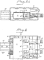
- Fig. 2
- is a broken view from above which shows the terminal connector device inserted into the terminal box although not fully connected thereto;
- Fig. 2A
- is a side view of the arrangement shown in Fig. 2;
- Fig. 3
- is a horizontal sectional view of the terminal connector device when fully connected to the terminal box;
- Fig. 4
- is a view from above of the terminal connector device and its pivotal engagement means; and
- Fig. 5
- is an electric signal flowsheet and also illustrates schematically the electrical coaction achieved when the terminal connector device is inserted in the terminal box.
Claims (4)
- A multi-facility connection arrangement comprising a terminal connector device (11) with first connecting means (30''', 31''', 32''', 33') and a terminal box (15) with corresponding second connection means (62, 63, 64, 66), which terminal box (15) is adapted to be mounted on a vehicle and connected to pipes and conductors of a heating system, an electric system and a pressure system of the vehicle, and which terminal connector device (11) is arranged to be connected to corresponding sources of hot liquid, electric current and compressed air on a stationary plant characterised in, that the terminal connector device (11) is arranged to be inserted into the terminal box (15), which terminal box (15) contains a microswitch (70) adapted to be activated upon insertion of the terminal connector device (11), which microswitch (70) when activated is arranged to activate at least one piston/cylinder device (67), which at least one piston/cylinder device (67) when activated is arranged to move the terminal connector device (11) and thereby bring the first connecting means (30''', 31''', 32''',33') into active connection with the corresponding second connecting means (62, 63, 64, 66) and thereby connect the vehicle systems to the corresponding sources on the stationary plant.
- An arrangement according to Claim 1, characterised in that the terminal connector device (11) has pivotally mounted thereon an activator (41) which is provided with an externally accessible handgrip (42) and which can be locked in a position in which the microswitch (70) is activated and locked in its activated state.
- An arrangement according to Claim 1, characterised in that the microswitch (70) is adapted to deliver a control signal to a solenoid valve (71) upon activation of the activator (41), such as to activate the piston/cylinder device or devices (67).
- An arrangement according to any one of Claims 1-3, characterised in that the microswitch (70) is connected electrically to an electrical terminal box (72) for controlling different signal commands and the functions to which they are directed, which functions include the activation of at least one temperature regulating facility and activation of a vehicle ignition locking facility.
Applications Claiming Priority (3)
| Application Number | Priority Date | Filing Date | Title |
|---|---|---|---|
| SE9401182A SE502704C2 (en) | 1994-04-08 | 1994-04-08 | Device for heating systems, for parked cargo or passenger vehicles, especially buses in scheduled services |
| SE9401182 | 1994-04-08 | ||
| EP95916079A EP0701512A1 (en) | 1994-04-08 | 1995-04-06 | A multi-facility connection arrangement |
Related Parent Applications (1)
| Application Number | Title | Priority Date | Filing Date |
|---|---|---|---|
| EP95916079A Division EP0701512A1 (en) | 1994-04-08 | 1995-04-06 | A multi-facility connection arrangement |
Publications (3)
| Publication Number | Publication Date |
|---|---|
| EP0855299A2 true EP0855299A2 (en) | 1998-07-29 |
| EP0855299A3 EP0855299A3 (en) | 1999-02-24 |
| EP0855299B1 EP0855299B1 (en) | 2000-10-18 |
Family
ID=20393577
Family Applications (2)
| Application Number | Title | Priority Date | Filing Date |
|---|---|---|---|
| EP98103939A Expired - Lifetime EP0855299B1 (en) | 1994-04-08 | 1995-04-06 | A multi-facility connection arrangement |
| EP95916079A Withdrawn EP0701512A1 (en) | 1994-04-08 | 1995-04-06 | A multi-facility connection arrangement |
Family Applications After (1)
| Application Number | Title | Priority Date | Filing Date |
|---|---|---|---|
| EP95916079A Withdrawn EP0701512A1 (en) | 1994-04-08 | 1995-04-06 | A multi-facility connection arrangement |
Country Status (7)
| Country | Link |
|---|---|
| EP (2) | EP0855299B1 (en) |
| AT (1) | ATE197020T1 (en) |
| DE (1) | DE69519178T2 (en) |
| DK (1) | DK0855299T3 (en) |
| ES (1) | ES2153694T3 (en) |
| SE (1) | SE502704C2 (en) |
| WO (1) | WO1995027630A1 (en) |
Cited By (2)
| Publication number | Priority date | Publication date | Assignee | Title |
|---|---|---|---|---|
| EP1961367A1 (en) * | 2007-02-22 | 2008-08-27 | invendo medical GmbH | Electric plug device with integrated hydraulic/pneumatic connections |
| EP1989073A1 (en) * | 2006-02-27 | 2008-11-12 | Jp Ei&Vvs Teknik Ab | A docking unit for heating/cooling a parked vehicle, as well as a vehicle arranged to be connected to such a docking unit |
Family Cites Families (4)
| Publication number | Priority date | Publication date | Assignee | Title |
|---|---|---|---|---|
| SE440734B (en) * | 1981-11-25 | 1985-08-19 | El & Dieselservice Ab | Device for vehicles, especially busses, designed for maintaining a constant amount of liquid in the vehicle's liquid-bearing heating system |
| US4624472A (en) * | 1984-01-18 | 1986-11-25 | Stuart Clifton F | Coupling mechanism for coupling fluid and electrical lines between adjacent vehicles |
| JP2912631B2 (en) * | 1989-05-17 | 1999-06-28 | 津田駒工業株式会社 | Automatic detachable connector device |
| US5462439A (en) * | 1993-04-19 | 1995-10-31 | Keith; Arlie L. | Charging batteries of electric vehicles |
-
1994
- 1994-04-08 SE SE9401182A patent/SE502704C2/en not_active IP Right Cessation
-
1995
- 1995-04-06 DE DE69519178T patent/DE69519178T2/en not_active Expired - Fee Related
- 1995-04-06 WO PCT/SE1995/000369 patent/WO1995027630A1/en not_active Application Discontinuation
- 1995-04-06 ES ES98103939T patent/ES2153694T3/en not_active Expired - Lifetime
- 1995-04-06 EP EP98103939A patent/EP0855299B1/en not_active Expired - Lifetime
- 1995-04-06 DK DK98103939T patent/DK0855299T3/en active
- 1995-04-06 EP EP95916079A patent/EP0701512A1/en not_active Withdrawn
- 1995-04-06 AT AT98103939T patent/ATE197020T1/en not_active IP Right Cessation
Non-Patent Citations (1)
| Title |
|---|
| None |
Cited By (4)
| Publication number | Priority date | Publication date | Assignee | Title |
|---|---|---|---|---|
| EP1989073A1 (en) * | 2006-02-27 | 2008-11-12 | Jp Ei&Vvs Teknik Ab | A docking unit for heating/cooling a parked vehicle, as well as a vehicle arranged to be connected to such a docking unit |
| EP1989073A4 (en) * | 2006-02-27 | 2010-03-10 | Jp Ei & Vvs Teknik Ab | A docking unit for heating/cooling a parked vehicle, as well as a vehicle arranged to be connected to such a docking unit |
| EP1961367A1 (en) * | 2007-02-22 | 2008-08-27 | invendo medical GmbH | Electric plug device with integrated hydraulic/pneumatic connections |
| US7621766B2 (en) | 2007-02-22 | 2009-11-24 | Invendo Medical Gmbh | Electric plug device including integrated hydraulic/pneumatic ports |
Also Published As
| Publication number | Publication date |
|---|---|
| DE69519178D1 (en) | 2000-11-23 |
| EP0701512A1 (en) | 1996-03-20 |
| WO1995027630A1 (en) | 1995-10-19 |
| DK0855299T3 (en) | 2001-02-05 |
| SE9401182L (en) | 1995-10-09 |
| EP0855299B1 (en) | 2000-10-18 |
| EP0855299A3 (en) | 1999-02-24 |
| SE502704C2 (en) | 1995-12-11 |
| ATE197020T1 (en) | 2000-11-15 |
| SE9401182D0 (en) | 1994-04-08 |
| ES2153694T3 (en) | 2001-03-01 |
| DE69519178T2 (en) | 2001-05-31 |
Similar Documents
| Publication | Publication Date | Title |
|---|---|---|
| US9114716B2 (en) | Method and apparatus for high-voltage DC charging of battery-electric and plug-in hybrid electric vehicles | |
| US3497027A (en) | Electric automobile | |
| CN103036109B (en) | Locking apparatus for electric vehicle charging connector | |
| US4414462A (en) | Tank car heating system | |
| US20200044464A1 (en) | Fast rechargeable battery assembly and recharging equipment | |
| EP3790145A1 (en) | Power distribution unit for managing transport climate control loads | |
| US6817879B2 (en) | Service port configurations | |
| EP1548901B1 (en) | An external power source connecting device for an electric vehicle | |
| CN102105337B (en) | Automatic brake | |
| JPH04334906A (en) | Electric motor vehicle with auxiliary power source | |
| EP0855299B1 (en) | A multi-facility connection arrangement | |
| CN110293856A (en) | Equipped with the electrified vehicle of secondary battery group | |
| SE542943C2 (en) | A charging device for a functional module and a vehicle assembled from a set of modules | |
| US20210234319A1 (en) | Optimized power cord for transferring power to a transport climate control system | |
| US11370315B2 (en) | Hands-free charging system with internal power source | |
| US11839782B2 (en) | Safety method and control device for an emergency vehicle | |
| DE102020211783A1 (en) | Trailer with a power generator | |
| EP4140884A1 (en) | Interface system for connecting trolleys | |
| CN114156103B (en) | Maintenance switch, control method of maintenance switch and electric automobile | |
| EP3718869A1 (en) | Maneuvering drive system, vehicle with a maneuvering drive system and kit with a maneuvering drive system and a loading device | |
| DE102021129893A1 (en) | System and method for transferring thermal and electrical energy |
Legal Events
| Date | Code | Title | Description |
|---|---|---|---|
| PUAI | Public reference made under article 153(3) epc to a published international application that has entered the european phase |
Free format text: ORIGINAL CODE: 0009012 |
|
| 17P | Request for examination filed |
Effective date: 19980316 |
|
| AC | Divisional application: reference to earlier application |
Ref document number: 701512 Country of ref document: EP |
|
| AK | Designated contracting states |
Kind code of ref document: A2 Designated state(s): AT BE CH DE DK ES FR GB IE IT LI NL PT |
|
| PUAL | Search report despatched |
Free format text: ORIGINAL CODE: 0009013 |
|
| AK | Designated contracting states |
Kind code of ref document: A3 Designated state(s): AT BE CH DE DK ES FR GB IE IT LI NL PT |
|
| GRAG | Despatch of communication of intention to grant |
Free format text: ORIGINAL CODE: EPIDOS AGRA |
|
| 17Q | First examination report despatched |
Effective date: 19991213 |
|
| GRAG | Despatch of communication of intention to grant |
Free format text: ORIGINAL CODE: EPIDOS AGRA |
|
| GRAH | Despatch of communication of intention to grant a patent |
Free format text: ORIGINAL CODE: EPIDOS IGRA |
|
| GRAH | Despatch of communication of intention to grant a patent |
Free format text: ORIGINAL CODE: EPIDOS IGRA |
|
| GRAA | (expected) grant |
Free format text: ORIGINAL CODE: 0009210 |
|
| AC | Divisional application: reference to earlier application |
Ref document number: 701512 Country of ref document: EP |
|
| AK | Designated contracting states |
Kind code of ref document: B1 Designated state(s): AT BE CH DE DK ES FR GB IE IT LI NL PT |
|
| REF | Corresponds to: |
Ref document number: 197020 Country of ref document: AT Date of ref document: 20001115 Kind code of ref document: T |
|
| REG | Reference to a national code |
Ref country code: CH Ref legal event code: EP |
|
| REG | Reference to a national code |
Ref country code: IE Ref legal event code: FG4D |
|
| REF | Corresponds to: |
Ref document number: 69519178 Country of ref document: DE Date of ref document: 20001123 |
|
| ET | Fr: translation filed | ||
| ITF | It: translation for a ep patent filed |
Owner name: STUDIO TORTA S.R.L. |
|
| PG25 | Lapsed in a contracting state [announced via postgrant information from national office to epo] |
Ref country code: PT Free format text: LAPSE BECAUSE OF FAILURE TO SUBMIT A TRANSLATION OF THE DESCRIPTION OR TO PAY THE FEE WITHIN THE PRESCRIBED TIME-LIMIT Effective date: 20010118 |
|
| REG | Reference to a national code |
Ref country code: CH Ref legal event code: NV Representative=s name: BUGNION S.A. |
|
| REG | Reference to a national code |
Ref country code: DK Ref legal event code: T3 |
|
| REG | Reference to a national code |
Ref country code: ES Ref legal event code: FG2A Ref document number: 2153694 Country of ref document: ES Kind code of ref document: T3 |
|
| PG25 | Lapsed in a contracting state [announced via postgrant information from national office to epo] |
Ref country code: IE Free format text: LAPSE BECAUSE OF NON-PAYMENT OF DUE FEES Effective date: 20010406 |
|
| PLBE | No opposition filed within time limit |
Free format text: ORIGINAL CODE: 0009261 |
|
| STAA | Information on the status of an ep patent application or granted ep patent |
Free format text: STATUS: NO OPPOSITION FILED WITHIN TIME LIMIT |
|
| 26N | No opposition filed | ||
| REG | Reference to a national code |
Ref country code: GB Ref legal event code: IF02 |
|
| REG | Reference to a national code |
Ref country code: IE Ref legal event code: MM4A |
|
| PGFP | Annual fee paid to national office [announced via postgrant information from national office to epo] |
Ref country code: GB Payment date: 20040325 Year of fee payment: 10 |
|
| PGFP | Annual fee paid to national office [announced via postgrant information from national office to epo] |
Ref country code: FR Payment date: 20040330 Year of fee payment: 10 |
|
| PGFP | Annual fee paid to national office [announced via postgrant information from national office to epo] |
Ref country code: NL Payment date: 20040415 Year of fee payment: 10 |
|
| PGFP | Annual fee paid to national office [announced via postgrant information from national office to epo] |
Ref country code: BE Payment date: 20040422 Year of fee payment: 10 |
|
| PGFP | Annual fee paid to national office [announced via postgrant information from national office to epo] |
Ref country code: DK Payment date: 20040426 Year of fee payment: 10 |
|
| PG25 | Lapsed in a contracting state [announced via postgrant information from national office to epo] |
Ref country code: IT Free format text: LAPSE BECAUSE OF NON-PAYMENT OF DUE FEES Effective date: 20050406 Ref country code: GB Free format text: LAPSE BECAUSE OF NON-PAYMENT OF DUE FEES Effective date: 20050406 |
|
| PGFP | Annual fee paid to national office [announced via postgrant information from national office to epo] |
Ref country code: CH Payment date: 20050414 Year of fee payment: 11 |
|
| PGFP | Annual fee paid to national office [announced via postgrant information from national office to epo] |
Ref country code: ES Payment date: 20050422 Year of fee payment: 11 |
|
| PGFP | Annual fee paid to national office [announced via postgrant information from national office to epo] |
Ref country code: AT Payment date: 20050426 Year of fee payment: 11 |
|
| PGFP | Annual fee paid to national office [announced via postgrant information from national office to epo] |
Ref country code: DE Payment date: 20050427 Year of fee payment: 11 |
|
| PG25 | Lapsed in a contracting state [announced via postgrant information from national office to epo] |
Ref country code: BE Free format text: LAPSE BECAUSE OF NON-PAYMENT OF DUE FEES Effective date: 20050430 |
|
| PG25 | Lapsed in a contracting state [announced via postgrant information from national office to epo] |
Ref country code: DK Free format text: LAPSE BECAUSE OF NON-PAYMENT OF DUE FEES Effective date: 20050502 |
|
| BERE | Be: lapsed |
Owner name: *UWE-VERKEN A.B. Effective date: 20050430 |
|
| PG25 | Lapsed in a contracting state [announced via postgrant information from national office to epo] |
Ref country code: NL Free format text: LAPSE BECAUSE OF NON-PAYMENT OF DUE FEES Effective date: 20051101 |
|
| REG | Reference to a national code |
Ref country code: DK Ref legal event code: EBP |
|
| GBPC | Gb: european patent ceased through non-payment of renewal fee |
Effective date: 20050406 |
|
| PG25 | Lapsed in a contracting state [announced via postgrant information from national office to epo] |
Ref country code: FR Free format text: LAPSE BECAUSE OF NON-PAYMENT OF DUE FEES Effective date: 20051230 |
|
| NLV4 | Nl: lapsed or anulled due to non-payment of the annual fee |
Effective date: 20051101 |
|
| REG | Reference to a national code |
Ref country code: FR Ref legal event code: ST Effective date: 20051230 |
|
| PG25 | Lapsed in a contracting state [announced via postgrant information from national office to epo] |
Ref country code: AT Free format text: LAPSE BECAUSE OF NON-PAYMENT OF DUE FEES Effective date: 20060406 |
|
| PG25 | Lapsed in a contracting state [announced via postgrant information from national office to epo] |
Ref country code: ES Free format text: LAPSE BECAUSE OF NON-PAYMENT OF DUE FEES Effective date: 20060407 |
|
| PG25 | Lapsed in a contracting state [announced via postgrant information from national office to epo] |
Ref country code: LI Free format text: LAPSE BECAUSE OF NON-PAYMENT OF DUE FEES Effective date: 20060430 Ref country code: CH Free format text: LAPSE BECAUSE OF NON-PAYMENT OF DUE FEES Effective date: 20060430 |
|
| PG25 | Lapsed in a contracting state [announced via postgrant information from national office to epo] |
Ref country code: DE Free format text: LAPSE BECAUSE OF NON-PAYMENT OF DUE FEES Effective date: 20061101 |
|
| REG | Reference to a national code |
Ref country code: CH Ref legal event code: PL |
|
| REG | Reference to a national code |
Ref country code: ES Ref legal event code: FD2A Effective date: 20060407 |
|
| BERE | Be: lapsed |
Owner name: *UWE-VERKEN A.B. Effective date: 20050430 |