EP0851632A2 - Wireless relay with selective message repeat and method of operation thereof - Google Patents
Wireless relay with selective message repeat and method of operation thereof Download PDFInfo
- Publication number
- EP0851632A2 EP0851632A2 EP97310018A EP97310018A EP0851632A2 EP 0851632 A2 EP0851632 A2 EP 0851632A2 EP 97310018 A EP97310018 A EP 97310018A EP 97310018 A EP97310018 A EP 97310018A EP 0851632 A2 EP0851632 A2 EP 0851632A2
- Authority
- EP
- European Patent Office
- Prior art keywords
- station
- message
- received
- unicast message
- destination end
- Prior art date
- Legal status (The legal status is an assumption and is not a legal conclusion. Google has not performed a legal analysis and makes no representation as to the accuracy of the status listed.)
- Granted
Links
- 238000000034 method Methods 0.000 title claims abstract description 18
- 238000012544 monitoring process Methods 0.000 claims description 3
- 230000005540 biological transmission Effects 0.000 description 5
- 238000012545 processing Methods 0.000 description 5
- 238000004891 communication Methods 0.000 description 4
- 238000010586 diagram Methods 0.000 description 4
- 238000001228 spectrum Methods 0.000 description 2
- 230000004075 alteration Effects 0.000 description 1
- 238000010276 construction Methods 0.000 description 1
- 230000007812 deficiency Effects 0.000 description 1
- 230000009365 direct transmission Effects 0.000 description 1
- 238000004519 manufacturing process Methods 0.000 description 1
- 230000008054 signal transmission Effects 0.000 description 1
- 238000006467 substitution reaction Methods 0.000 description 1
- 238000012546 transfer Methods 0.000 description 1
- 239000002699 waste material Substances 0.000 description 1
Images


Classifications
-
- H—ELECTRICITY
- H04—ELECTRIC COMMUNICATION TECHNIQUE
- H04L—TRANSMISSION OF DIGITAL INFORMATION, e.g. TELEGRAPHIC COMMUNICATION
- H04L1/00—Arrangements for detecting or preventing errors in the information received
- H04L1/12—Arrangements for detecting or preventing errors in the information received by using return channel
- H04L1/16—Arrangements for detecting or preventing errors in the information received by using return channel in which the return channel carries supervisory signals, e.g. repetition request signals
- H04L1/18—Automatic repetition systems, e.g. Van Duuren systems
- H04L1/1809—Selective-repeat protocols
-
- H—ELECTRICITY
- H04—ELECTRIC COMMUNICATION TECHNIQUE
- H04L—TRANSMISSION OF DIGITAL INFORMATION, e.g. TELEGRAPHIC COMMUNICATION
- H04L1/00—Arrangements for detecting or preventing errors in the information received
- H04L2001/0092—Error control systems characterised by the topology of the transmission link
-
- H—ELECTRICITY
- H04—ELECTRIC COMMUNICATION TECHNIQUE
- H04W—WIRELESS COMMUNICATION NETWORKS
- H04W84/00—Network topologies
- H04W84/02—Hierarchically pre-organised networks, e.g. paging networks, cellular networks, WLAN [Wireless Local Area Network] or WLL [Wireless Local Loop]
- H04W84/10—Small scale networks; Flat hierarchical networks
- H04W84/12—WLAN [Wireless Local Area Networks]
-
- H—ELECTRICITY
- H04—ELECTRIC COMMUNICATION TECHNIQUE
- H04W—WIRELESS COMMUNICATION NETWORKS
- H04W88/00—Devices specially adapted for wireless communication networks, e.g. terminals, base stations or access point devices
- H04W88/02—Terminal devices
- H04W88/04—Terminal devices adapted for relaying to or from another terminal or user
Definitions
- the present invention is directed, in general, to a wireless computer network and, more specifically, to systems and methods for selectively repeating messages in a wireless computer network.
- LANs local area networks
- ISM industrial, scientific and medical
- Wireless LAN products most often employ either direct sequence spread spectrum (“DSSS”) or frequency-hopping spread spectrum (“FHSS”) techniques to communicate between roaming mobile stations and network access points.
- DSSS direct sequence spread spectrum
- FHSS frequency-hopping spread spectrum
- the "backbone" of the LAN takes the form of one or more central servers that communicate with a number of network access points ("APs") through a hard-wired connection.
- Each AP includes a transceiver for communicating with at least one roaming mobile station ("MS").
- the mobile station may be a point-of-sale terminal (e.g ., an electronic cash register), a bar code reader or other scanning device, or a notepad, desktop or laptop computer.
- Each MS establishes a communication link with an AP by scanning the ISM band to find an available AP. Once a reliable link is established, the MS interacts with other mobile stations, a server or both. This allows the user of the MS to move freely in the office, factory, hospital or other facility where the wireless LAN is based, without the length of a hard-wired connection to the LAN limiting the movement of the MS user.
- Radio relays functions as repeaters to relay messages from one mobile station to another mobile station (peer-to-peer traffic) or from a mobile station to an access point. This allows the communication link to be maintained even if the distance between the two communicating end-stations (whether mobile station or access point) is greater than the range of the transceiver of either or both devices. This also allows the communication link to be maintained even when a radio block obstructs the path between the two end-stations.
- a conventional radio blindly repeats any wireless message that it receives. This has the unfortunate drawback of consuming already limited radio bandwidth in those cases where the two end-stations that are communicating are within direct radio range of each other. In such a case, the repeated message is redundant and time-consuming. This situation is exacerbated when an end-station improperly receives the message, as when a redundancy check fails, and the receiver requests that the message be retransmitted. The radio relay repeats the retransmitted message, thereby consuming even more bandwidth.
- the present invention provides, for use in a wireless computer network having a radio relay capable of transmitting messages, a system and method, operable with the radio relay, for selectively repeating a unicast message received from a source end-station only upon some indication that a destination end-station has not received the message.
- the system includes: (1) a transceiver that receives the unicast message from the source end-station and (2) control circuitry, coupled to the transceiver, that determines whether the destination end-station has received the unicast message and causes the transceiver to refrain from repeating the unicast message if the destination end-station has received the unicast message, the radio relay thereby freed from repeating already-received unicast messages.
- the present invention therefore recognizes that indiscriminate repeating of unicast messages by radio relays, while simple to implement, represents a considerable and completely avoidable waste of wireless computer network resources.
- the present invention responds by basing a decision of whether to repeat on whether the destination end-station has received the unicast message. If so, the radio relay refrains from wirelessly repeating the message, thereby covering situations in which the destination end-station is in direct range of the source end-station. If not, the radio relay wirelessly repeats the message so the destination end-station can receive it.
- the control circuitry determines whether the destination end-station has received the unicast message by monitoring the transceiver for receipt of an acknowledgment from the destination end-station.
- the present invention can operate in a wireless LAN environment, wherein Wireless InterFrame Spaces ("WIFS") separate individual messages.
- the WIFS provide a time period within which the radio relay and the destination end-station can acknowledge messages with BLEEP signals: R-BLEEPS and S-BLEEPS for radio relays and stations, respectively.
- the destination end-station refrains from acknowledging the unicast message if the destination end-station fails to confirm that the unicast message is error-free. By so refraining, the radio relay repeats the unicast message, thereby giving the destination end-station a better opportunity to receive the message.
- control circuitry is capable of causing the transceiver to acknowledge the unicast message, the control circuitry causing the transceiver to refrain from acknowledging the unicast message if the control circuitry fails to confirm that the unicast message is error-free.
- the radio relay can refrain from acknowledging the unicast message if it was received with errors.
- the source end-station retransmits the message, thereby giving the radio relay a second opportunity to receive the message.
- control circuitry causes the transceiver to repeat a multicast message received from the source end-station without regard as to whether the destination end-station has received the multicast message.
- multicast messages are not acknowledged. Therefore, the present invention does not selectively repeat such messages.
- control circuitry is coupled to a wire-based LAN via a bridge, the control circuitry transmitting the unicast message to the LAN via the bridge without regard as to whether the destination end-station has received the unicast message.
- the LAN is therefore able to process the message in any desirable manner.
- the control circuitry is coupled to a wire-based LAN via a bridge, the LAN receiving the unicast message from the control circuitry via the bridge without regard as to whether the destination end-station has received the unicast message, the LAN further searching a bridge filter table associated therewith for a destination address corresponding to the destination end-station.
- the LAN may employ the bridge filter table to determine a logical location within the LAN at which the destination end-station may be located. This furthers routing of the message within the LAN.
- Server 105 of wireless network 100 communicates bi-directionally with access points 110-112 via bus 106, which is typically a hard-wired connection. In other embodiments, server 105 may communicate with one or more of access points 110-112 by wireless link. AP 110-112 also communicate with one or more mobile stations (MS) 120-123 and 130-132 by wireless link. Each access point can transmit data to and receive data from mobile stations that are within the specified broadcast range of the access point. For example, AP 110 and AP 111 have broadcast ranges 140 and 141, respectively. AP 111 can communicate with MS 130, MS 131, MS 132 and MS 122. AP 110 can communicate directly with MS 120, MS 121 and MS 122, or indirectly with MS 123 through relay station (RS) 150, as will be explained below in greater detail.
- RS relay station
- the exemplary broadcast coverage areas of AP 110 and AP 111 are circular in shape, it is possible for the broadcast area of an access point to assume other shapes, including hexagonal.
- the shape and size of the coverage area of an access point is frequently determined by obstructions that prevent the transmission of signals between the access point and a mobile station.
- network 100 may be a wireless LAN in an office building.
- Mobile stations 120-122 and 130-132 are typically desktop and/or notebook computers that communicate with a document server, such as server 105, or run payroll or spreadsheet applications in connection with a server.
- network 100 may be a wireless LAN used to run the operations of a warehouse facility or manufacturing plant. Employees roaming the warehouse or factory floor, or even moving outside the facility, could communicate with a central server using a wide variety of mobile stations. For example, employees could use bar code scanners to send and receive data to/from server 105 through AP 110-112. Still other employees may be roam a facility using notepad devices to update inventory in server 105.
- network 100 may be a wireless LAN in a large department store and mobile stations 120-122 and 130-132 may be electronic cash registers and/or bar code readers.
- MS 122 will move out of the coverage range of its current access point, AP 110, to the new access point, AP 111.
- MS 122 determines that the signal quality of the link with current AP 110 has degraded below (or at least close to) an acceptable threshold level.
- MS 110 begins scanning for another AP in order to set up a "handover". The handover causes the communication link with current AP 110 to be broken down and a new link to be established with AP 111. Ideally, the handover will appear seamless to the user of MS 122.
- wireless computer network 100 employs one or more relays (or repeaters) that may be incorporated into mobile stations, access points, or both.
- AP 110 can communicate with MS 123 via dedicated relay station (RS) 150, even though MS 123 is beyond broadcast range 140 of AP 110.
- RS relay station
- One or more of the access points or mobile stations may be dedicated relays (such as RS 150) that perform no function other than relaying messages.
- the relay is said to be a "bridging relay".
- a bridging relay is a combination of a relay and a medium access control (MAC) level bridge that can retransmit a received message through the air, or can send the received message to its destination through the hard-wired "backbone" of the wireless computer system.
- MAC medium access control
- MS 122 and RS 150 both function as selective relays (in addition to other possible functions) in accordance with the present invention and that AP 110 functions as a MAC level bridge relay to the wired backbone of computer network 100 in accordance with the present invention.
- various components of computer network 100 may be described as either a "source end-station” or a "destination end-station,” whether the component involved is an access point or a mobile station.
- a source end-station is the original transmitter of an end-station to end-station message.
- a destination end-station is the ultimate destination of the message transmitted by the source end-station.
- a "unicast" message is one sent by a single source end-station to a single destination end-station
- a "multicast” message is one sent by a single source end-station to multiple destination end-stations, usually a class of end-stations that may be identified by a multicast address.
- a broadcast message is one sent by a single source end-station to all destination end-stations in computer network 100.
- MS 120, MS 121 and MS 122 are near the outer limits of the broadcast range of AP 110. Additionally, MS 120 and MS 121 are out of range of one another. If MS 120, acting as a source end-station, transmits a message intended for MS 121, the destination end-station, the signal will not reach MS 121 unless a relay is present. In this case, MS 122 functions as a selective relay and repeats the message transmitted by the source end-station, MS 120, when the relay function of MS 122 determines that there is some indication that MS 121 has not received the message sent by MS 120.
- the bridging relay function of AP 110 could selectively repeat the message transmitted by MS 120 when the relay function of AP 110 determines that there is some indication that MS 121 has not received the message sent by MS 120.
- RS 150 functions as a selective relay and repeats all message traffic it receives, including messages to and from AP 110 and MS 123.
- the "indication" that selective relays in accordance with the present invention look for is a BLEEP signal that is transmitted shortly after the reception of a message and that is sufficiently brief in duration that it fits in the Wireless Inter Frame Space (WIFS) employed by many wireless computer networks.
- Two "BLEEP” signals are employed by wireless networks according to the present invention.
- a Relay-BLEEP (R-BLEEP) signal is transmitted by a relay immediately after the end of the message transmitted by the source end-station.
- a Station BLEEP (S-BLEEP) signal is transmitted by the destination end-station immediately after the end of the time slot reserved for the R-BLEEP signal. Both BLEEP signals notify the source end-station of the reception of the message, as will be described in greater detail below. If neither BLEEP signal is detected by the source end-station, the source end-station will schedule the message for retransmission.
- FIGURE 2 there is illustrated a timing diagram 200 depicting the sequence of R-BLEEP and S-BLEEP signals in the Wireless Interframe Space (WIFS) according to one embodiment of the present invention.
- a relay transmits an R-BLEEP signal, indicating to the source end-station that the relay has received the message.
- the destination end-station transmits an S-BLEEP signal, indicating to the source end-station and to the relay that the destination end-station has received the message.
- the destination end-station transmits an S-BLEEP regardless whether or not an R-BLEEP signal is observed.
- the selective relay Since the time slots for an R-BLEEP and an S-BLEEP do not overlap, the selective relay will always be able to detect the S-BLEEP sent by the receiving end-station, if one is sent. When the relay detects the S-BLEEP signal, the selective relay will refrain from repeating the message, thereby conserving bandwidth.
- the selective relay or the destination end-station perform a redundancy check on the received message and transmit an R-BLEEP or an S-BLEEP, respectively, only if the message is received error-free.
- a selective relay in accordance with the present invention that has received the message error-free will transmit an R-BLEEP to the source end-station and then repeat the message to the destination end-station. If neither an R-BLEEP nor an S-BLEEP is detected by the source end-station because both the relay and the destination end-station detected errors in the received message, the source end-station will schedule the message for retransmission.
- FIGURES 3-6 are logical flow diagrams that illustrate the operation of selective relays, source end-stations and destination end-stations in a computer network according to the present invention.
- FIGURE 3 depicts flow chart 300, which illustrates the operation of a source end-station transmitting a unicast message to a destination end-station.
- the source end-station After transmitting the message (Step 310), the source end-station waits momentarily to detect either an R-BLEEP or an S-BLEEP, or both, in the WIFS (Steps 320 and 330). If no BLEEP message is received, the source end-station reports the status "NO TRANSFER" for the message (Step 350).
- the source end-station maintains a count of the number of transmissions of a particular message. When the transmission count reaches a maximum value, the source end-station ceases retransmission of the message and marks the message "undelivered" (Steps 360 and 370). If the transmission count is below the maximum value, the source end-station will schedule the message for retransmission (Step 310). A source end-statio transmitting a multicast message will not wait for a BLEEP signal.
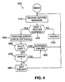
- FIGURE 4 depicts flow chart 400, which illustrates the operation of a destination end-station receiving a unicast message.
- the destination end-station After receiving a message (Step 410), the destination end-station verifies the address information in the header set (Step 420). If the recipient address in the header is not the same as the destination end-station's address, the destination end-station will ignore the message (Step 430).
- the destination end-station will transmit an S-BLEEP after an appropriate delay to allow any intervening R-BLEEP to be transmitted. If the destination end-station determines that the message is a multicast or broadcast message, the destination end-station will suppress the S-BLEEP (Steps 450, 460 and 480). Optionally, the destination end-station may perform a redundancy error check to verify that the message was received error free. In not, the destination end-station suppresses the S-BLEEP (Steps 440 and 470).
- FIGURE 5 depicts flow chart 500, which illustrates the operation of a plain relay receiving a unicast message (a plain relay will repeat all multicast messages, without looking for S-BLEEP signals).
- a plain relay may act as an end-station in addition to its role as a relay.
- the relay After receiving a unicast message (Step 505), the relay verifies the address information in the header set (Step 510). If the recipient address in the header is not the same as the relay's address, the relay transmits an R-BLEEP (Step 535) and looks to see if an S-BLEEP occurs in the WIFS after the R-BLEEP (Step 545).
- the relay may perform a redundancy error check to verify that the message was received error-free (Steps 515 and 525). If the message contains an error, the relay suppresses the R-BLEEP (Step 530) and further ignores the message (Step 540). If the message does not contain an error, the relay transmits an R-BLEEP (Step 535), as before, and verifies that an S-BLEEP occurs in the WIFS after the R-BLEEP (Step 545).
- the relay ignores (i.e., does not repeat) the message, because the destination end-station has received the message (Step 540).
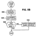
- the non-repetition of the message advantageously conserves bandwidth. If, however, the selective relay does not detect an S-BLEEP in the WIFS, the relay determines that the destination end-station did not receive the message and sets the status of the message to "REPEAT" (Step 580).
- the selective relay then retransmits the message in the same manner as the source end-station, namely, the relay maintains a transmission count to avoid endless retransmission of the message (Steps 585 and 590) and retransmits the message using the original source address of the source end-station (Step 595).
- the re-transmitted message is indistinguishable from the original message transmitted by the source end-station.
- Step 555 the relay transmits an S-BLEEP (Step 555), and then reports the status of the message as "MESSAGE RECEIVED" (Step 570). Since the message was intended for the relay, the message is then forwarded on to the other functions of the relay for further processing (Step 575).
- the relay must transmit an S-BLEEP, and not merely an R-BLEEP, because it is possible that another relay (a non-destination relay) can also hear the message. In such a case, the non-destination relay would not hear the R-BLEEP sent by the intended destination relay because the non-destination relay would be transmitting its own R-BLEEP at about the same time. Unless an S-BLEEP was sent by the intended destination relay, the non-destination relay would then incorrectly repeat the message despite the fact that it was correctly received by the intended destination relay.
- the relay may perform a redundancy error check to verify that the message was received error-free (Steps 520 and 550). If the message contains an error, the relay suppresses the S-BLEEP (Step 560) and further ignores the message (Step 565). If the message does not contain an error, the relay transmits an S-BLEEP (Step 555), as before, reports the status of the message as "MESSAGE RECEIVED" (Step 570), and forwards the message to the other functions of the relay for further processing (Step 575).
- FIGURE 6 depicts flow chart 600, which illustrates the operation of a MAC bridge relay receiving a unicast message (a bridge relay will repeat all multicast messages, without looking for S-BLEEP signals).
- a bridge relay may act as an end-station in addition to its role as a relay.
- the bridge relay After receiving a unicast message (Step 605), the bridge relay verifies the address information in the header set (Step 610). If the recipient address in the header is not the same as the bridge relay's address, the bridge relay transmits an R-BLEEP (Step 635) and looks to see if an S-BLEEP occurs in the WIFS after the R-BLEEP (Step 645).
- the bridge relay may perform a redundancy error check to verify that the message was received error-free (Steps 615 and 625). If the message contains an error, the bridge relay suppresses the R-BLEEP (Step 630) and further ignores the message (Step 640). If the message does not contain an error, the bridge relay transmits an R-BLEEP (Step 635), as before, and verifies that an S-BLEEP occurs in the WIFS after the R-BLEEP (Step 645).
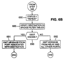
- the bridge relay may optionally report a status of "NO REPEAT" and send the received message to the bridge function (Steps 646-647). The bridge relay then ignores (i.e., does not repeat) the message, because the destination end-station has received the message (Step 640). Again, the non-repetition of the message advantageously conserves bandwidth. If, however, the bridge relay does not detect an S-BLEEP in the WIFS, the relay determines that the destination end-station did not receive the message and sets the status of the message to "REPEAT" (Step 680).
- the selective bridge relay then forwards the message to the bridge relay function and examines the bridge filter tables to determine if the destination end-station address is in the filter table (Steps 685 and 690). If the destination end-station is found, the message is retransmitted from the port on the bridge associated with the destination end-station (Step 691). If the destination end-station is not known, the message is retransmitted by the bridge relay and all other ports on the relay bridge (Step 692).
- Step 610 if the recipient address in the header is the same as the bridge relay's address, the bridge relay transmits an S-BLEEP (Step 655), and then report the status of the message as "MESSAGE RECEIVED" (Step 670). Since the message was intended for the relay, the message is then forwarded on to the other functions of the bridge relay for further processing (Step 675). As previously explained, the relay must transmit an S-BLEEP, and not merely an R-BLEEP, because it is possible that another relay (a non-destination relay) can also hear the message.
- the non-destination relay would not hear the R-BLEEP sent by the intended destination relay because the non-destination relay would be transmitting its own R-BLEEP at about the same time. Unless an S-BLEEP was sent by the intended destination relay, the non-destination relay would then incorrectly repeat the message despite the fact that it was correctly received by the intended destination relay.
- the bridge relay may perform a redundancy error check to verify that the message was received error-free (Steps 620 and 650). If the message contains an error, the relay suppresses the S-BLEEP (Step 660) and further ignores the message (Step 665). If the message does not contain an error, the relay transmits an S-BLEEP (Step 655), as before, reports the status of the message as "MESSAGE RECEIVED" (Step 670), and forwards the message to the other functions of the bridge relay for further processing (Step 675).
Landscapes
- Engineering & Computer Science (AREA)
- Computer Networks & Wireless Communication (AREA)
- Signal Processing (AREA)
- Mobile Radio Communication Systems (AREA)
- Data Exchanges In Wide-Area Networks (AREA)
- Small-Scale Networks (AREA)
- Synchronisation In Digital Transmission Systems (AREA)
- Radio Relay Systems (AREA)
Abstract
Description
Claims (17)
- For use in a wireless computer network having a radio relay capable of transmitting messages, a system, operable with said radio relay, for selectively repeating a unicast message received from a source end-station only upon some indication that a destination end-station has not received said message, said system comprising:a transceiver that receives said unicast message from said source end-station; andcontrol circuitry, coupled to said transceiver, that determines whether said destination end-station has received said unicast message and causes said transceiver to refrain from repeating said unicast message if said destination end-station has received said unicast message, said radio relay thereby freed from repeating already-received unicast messages.
- The system as recited in Claim 1 wherein said control circuitry is coupled to a wire-based local area network (LAN) via a bridge, said control circuitry transmitting said unicast message to said LAN via said bridge without regard as to whether said destination end-station has received said unicast message.
- The system as recited in Claim 1 wherein said control circuitry is coupled to a wire-based local area network (LAN) via a bridge, said LAN receiving said unicast message from said control circuitry via said bridge without regard as to whether said destination end-station has received said unicast message, said LAN further searching a bridge filter table associated therewith for a destination address corresponding to said destination end-station.
- For use in a wireless computer network having a radio relay capable of transmitting messages, a method, operable with said radio relay, of selectively repeating a unicast message received from a source end-station only upon some indication that a destination end-station has not received said message, said method comprising the steps of:receiving said unicast message from said source end-station;determining whether said destination end-station has received said unicast message; andrefraining from repeating said unicast message if said destination end-station has received said unicast message, said radio relay thereby freed from repeating already-received unicast messages.
- The method as recited in Claim 4 wherein said step of determining comprises the step of monitoring said transceiver for receipt of an acknowledgement from said destination end-station.
- The method as recited in Claim 4 further comprising the step of refraining from acknowledging said unicast message if said destination end-station fails to confirm that said unicast message is error-free.
- The method as recited in Claim 4 further comprising the step of refraining from acknowledging said unicast message if said radio relay fails to confirm that said unicast message is error-free.
- The method as recited in Claim 4 further comprising the step of repeating a multicast message received from said source end-station without regard as to whether said destination end-station has received said multicast message.
- The method as recited in Claim 4 wherein said radio relay is coupled to a wire-based local area network (LAN) via a bridge, said method further comprising the step of transmitting said unicast message to said LAN via said bridge without regard as to whether said destination end-station has received said unicast message.
- The method as recited in Claim 4 wherein said radio relay is coupled to a wire-based local area network (LAN) via a bridge, said method comprising the steps of:receiving said unicast message from said radio relay into said LAN via said bridge without regard as to whether said destination end-station has received said unicast message; andsearching a bridge filter table associated therewith for a destination address corresponding to said destination end-station.
- A wireless computer network, comprising:a wire-based local area network (LAN) having a server and a backbone;a plurality of bridges coupled to said backbone; anda corresponding plurality of radio relays coupled to said plurality of backbones and capable of transmitting unicast and multicast messages among a plurality of source and destination end-stations, each of said corresponding plurality of radio relays including a system for selectively repeating a unicast message received from a source end-station only upon some indication that a destination end-station has not received said message, said system including:a transceiver that receives said unicast message from said source end-station; andcontrol circuitry, coupled to said transceiver, that determines whether said destination end-station has received said unicast message and causes said transceiver to refrain from repeating said unicast message if said destination end-station has received said unicast message, said radio relay thereby freed from repeating already-received unicast messages.
- A system as claimed in claim 1 or a network as claimed in claim 11 wherein said control circuitry determines whether said destination end-station has received said unicast message by monitoring said transceiver for receipt of an acknowledgement from said destination end-station.
- A system as claimed in claim 1 or a network as claimed in claim 11 wherein said destination end-station refrains from acknowledging said unicast message if said destination end-station fails to confirm that said unicast message is error-free.
- A system as claimed in claim 1 or a network as claimed in claim 11 wherein said control circuitry is capable of causing said transceiver to acknowledge said unicast message, said control circuitry causing said transceiver to refrain from acknowledging said unicast message if said control circuitry fails to confirm that said unicast message is error-free.
- A system as claimed in claim 1 or a network as claimed in claim 11 wherein said control circuitry causes said transceiver to repeat a multicast message received from said source end-station without regard as to whether said destination end-station has received said multicast message.
- A network as claimed in claim 11 wherein said control circuitry transmits said unicast message to said LAN via a corresponding one of said plurality of bridges without regard as to whether said destination end-station has received said unicast message.
- A network as claimed in claim 11 wherein said LAN receives said unicast message from said control circuitry via a corresponding one of said plurality of bridges without regard as to whether said destination end-station has received said unicast message, said LAN searching a bridge filter table associated therewith for a destination address corresponding to said destination end-station.
Priority Applications (1)
| Application Number | Priority Date | Filing Date | Title |
|---|---|---|---|
| EP07075241A EP1808981B1 (en) | 1996-12-30 | 1997-12-11 | Wireless relay with selective message repeat and method of operation thereof |
Applications Claiming Priority (2)
| Application Number | Priority Date | Filing Date | Title |
|---|---|---|---|
| US775238 | 1996-12-30 | ||
| US08/775,238 US5898679A (en) | 1996-12-30 | 1996-12-30 | Wireless relay with selective message repeat and method of operation thereof |
Related Child Applications (1)
| Application Number | Title | Priority Date | Filing Date |
|---|---|---|---|
| EP07075241A Division EP1808981B1 (en) | 1996-12-30 | 1997-12-11 | Wireless relay with selective message repeat and method of operation thereof |
Publications (3)
| Publication Number | Publication Date |
|---|---|
| EP0851632A2 true EP0851632A2 (en) | 1998-07-01 |
| EP0851632A3 EP0851632A3 (en) | 2002-09-04 |
| EP0851632B1 EP0851632B1 (en) | 2007-04-25 |
Family
ID=25103768
Family Applications (2)
| Application Number | Title | Priority Date | Filing Date |
|---|---|---|---|
| EP07075241A Expired - Lifetime EP1808981B1 (en) | 1996-12-30 | 1997-12-11 | Wireless relay with selective message repeat and method of operation thereof |
| EP97310018A Expired - Lifetime EP0851632B1 (en) | 1996-12-30 | 1997-12-11 | Wireless relay with selective message repeat and method of operation thereof |
Family Applications Before (1)
| Application Number | Title | Priority Date | Filing Date |
|---|---|---|---|
| EP07075241A Expired - Lifetime EP1808981B1 (en) | 1996-12-30 | 1997-12-11 | Wireless relay with selective message repeat and method of operation thereof |
Country Status (4)
| Country | Link |
|---|---|
| US (1) | US5898679A (en) |
| EP (2) | EP1808981B1 (en) |
| JP (1) | JP3291460B2 (en) |
| DE (2) | DE69737647T2 (en) |
Cited By (12)
| Publication number | Priority date | Publication date | Assignee | Title |
|---|---|---|---|---|
| WO2000067434A1 (en) * | 1999-04-29 | 2000-11-09 | Reinder Eric Nederhoed | Radiographic network |
| WO2001015374A1 (en) * | 1999-08-24 | 2001-03-01 | Cedardell Limited | Method and apparatus for wireless communication |
| EP1146455A2 (en) * | 2000-04-06 | 2001-10-17 | Toshiba Tec Kabushiki Kaisha | Electronic shelf label system |
| WO2004002082A1 (en) * | 2002-06-21 | 2003-12-31 | Siemens Aktiengesellschaft | Method and communication station for transmitting data |
| EP1404141A1 (en) * | 2001-07-03 | 2004-03-31 | Matsushita Electric Industrial Co., Ltd. | Radio communication system and radio communication method |
| WO2005008947A1 (en) * | 2003-07-17 | 2005-01-27 | Koninklijke Philips Electronics N.V. | Packet retransmission for mimo systems using multipath transmission |
| DE102004009347A1 (en) * | 2004-02-26 | 2005-09-15 | Giesecke & Devrient Gmbh | Method and device for spreading messages |
| WO2010148123A3 (en) * | 2009-06-19 | 2011-03-24 | Research In Motion Limited | Uplink transmissions for type 2 relay |
| US8014336B2 (en) | 2006-12-18 | 2011-09-06 | Nokia Corporation | Delay constrained use of automatic repeat request for multi-hop communication systems |
| GB2489507A (en) * | 2011-03-31 | 2012-10-03 | Nec Corp | Cooperative transmission in a network comprising a number of relay nodes |
| WO2013028681A1 (en) * | 2011-08-22 | 2013-02-28 | Cisco Technology, Inc. | Dynamic multi-path forwarding for shared-media communication network |
| US8468412B2 (en) | 2009-06-19 | 2013-06-18 | Research In Motion Limited | Downlink transmissions for type 2 relay |
Families Citing this family (138)
| Publication number | Priority date | Publication date | Assignee | Title |
|---|---|---|---|---|
| US6407991B1 (en) * | 1993-05-06 | 2002-06-18 | Intermec Ip Corp. | Communication network providing wireless and hard-wired dynamic routing |
| US6285857B1 (en) * | 1997-05-01 | 2001-09-04 | At&T Corp. | Multi-hop telecommunications system and method |
| US20080220776A1 (en) * | 1997-07-30 | 2008-09-11 | Steven Tischer | Interface devices for facilitating communications between devices and communications networks |
| US20080207197A1 (en) | 1997-07-30 | 2008-08-28 | Steven Tischer | Apparatus, method, and computer-readable medium for interfacing devices with communications networks |
| US7149514B1 (en) | 1997-07-30 | 2006-12-12 | Bellsouth Intellectual Property Corp. | Cellular docking station |
| US6006254A (en) * | 1997-08-29 | 1999-12-21 | Mitsubishi Electric Information Technology Center America, Inc. | System for the reliable, fast, low-latency communication of object state updates over a computer network by combining lossy and lossless communications |
| EP0976211B1 (en) * | 1998-01-16 | 2007-02-28 | Symbol Technologies, Inc. | Infrastructure for wireless lans |
| DE69934931T2 (en) * | 1998-03-31 | 2007-11-15 | Koninklijke Philips Electronics N.V. | A method of radio range control, wireless radio communication device using this method, base station and handset therefor |
| FR2778303B1 (en) * | 1998-05-04 | 2000-06-02 | Alsthom Cge Alcatel | METHOD FOR TRANSFERRING A COMMUNICATION BETWEEN TWO RELAYS OF A CELL OF A CELLULAR DIGITAL RADIO-COMMUNICATION SYSTEM |
| US6558320B1 (en) * | 2000-01-20 | 2003-05-06 | Medtronic Minimed, Inc. | Handheld personal data assistant (PDA) with a medical device and method of using the same |
| KR100304648B1 (en) * | 1998-12-31 | 2001-09-29 | 윤종용 | Method for allocating resoures wireless in wireless communication system |
| US6104712A (en) * | 1999-02-22 | 2000-08-15 | Robert; Bruno G. | Wireless communication network including plural migratory access nodes |
| GB9911924D0 (en) * | 1999-05-21 | 1999-07-21 | Adaptive Broadband Ltd | A method and system for wireless connection to a wide area network |
| US8266657B2 (en) | 2001-03-15 | 2012-09-11 | Sling Media Inc. | Method for effectively implementing a multi-room television system |
| US6263503B1 (en) * | 1999-05-26 | 2001-07-17 | Neal Margulis | Method for effectively implementing a wireless television system |
| US6891820B1 (en) * | 1999-07-06 | 2005-05-10 | Broadcom Corporation | Utilization of the internet protocol to facilitate communication involving mobile devices |
| DE19950005A1 (en) * | 1999-10-18 | 2001-04-19 | Bernhard Walke | Range enhancement operating method for mobile radio communications base station uses mobile stations within normal range as relay stations for reaching mobile stations outside normal operating range |
| IL138097A0 (en) * | 2000-08-25 | 2003-06-24 | Rafael Armament Dev Authority | Method of managing a distributed communications system |
| US7010315B1 (en) * | 2000-03-01 | 2006-03-07 | Motorola, Inc. | Method and apparatus for assigning a remote unit a channel within a communication system |
| US7173923B2 (en) * | 2000-03-17 | 2007-02-06 | Symbol Technologies, Inc. | Security in multiple wireless local area networks |
| US7173922B2 (en) * | 2000-03-17 | 2007-02-06 | Symbol Technologies, Inc. | Multiple wireless local area networks occupying overlapping physical spaces |
| GB2362070B (en) * | 2000-05-05 | 2004-06-16 | Nokia Mobile Phones Ltd | Communication devices and method of communication |
| US6553228B1 (en) * | 2000-06-26 | 2003-04-22 | Motorola, Inc. | Method and apparatus for distributing processing load for decoding paging messages in a radio communication system |
| US20020059449A1 (en) * | 2000-06-27 | 2002-05-16 | Matthias Wandel | System and method for implementing local base stations |
| US6950413B1 (en) * | 2000-07-20 | 2005-09-27 | Jenn-Chorng Liou | Mutually-assisted proximity informer system and method with wireless devices |
| US7002933B1 (en) * | 2000-10-06 | 2006-02-21 | Mitsubishi Electric Research Laboratories, Inc. | Wireless mobile network with an adaptive locally linked mobile network for locally routing multimedia content |
| US7002932B1 (en) * | 2001-01-12 | 2006-02-21 | 3Com Corporation | Method and system for providing network connectivity and mobility while roaming |
| US6993327B2 (en) * | 2001-10-29 | 2006-01-31 | Motorola, Inc. | Multicast distribution of presence information for an instant messaging system |
| US6968198B2 (en) * | 2002-02-15 | 2005-11-22 | M/A-Com, Inc. | Data passing method and apparatus for wireless communication system |
| EP1769585A4 (en) * | 2002-03-01 | 2009-12-02 | Ipr Licensing Inc | System and method for joint maximal ratio combining using time-domain based signal processing |
| US6687492B1 (en) * | 2002-03-01 | 2004-02-03 | Cognio, Inc. | System and method for antenna diversity using joint maximal ratio combining |
| US6862456B2 (en) * | 2002-03-01 | 2005-03-01 | Cognio, Inc. | Systems and methods for improving range for multicast wireless communication |
| US6785520B2 (en) * | 2002-03-01 | 2004-08-31 | Cognio, Inc. | System and method for antenna diversity using equal power joint maximal ratio combining |
| US7145892B2 (en) * | 2002-03-05 | 2006-12-05 | Dell Products, L.P. | Method and apparatus for adaptive wireless information handling system bridging |
| US6871049B2 (en) * | 2002-03-21 | 2005-03-22 | Cognio, Inc. | Improving the efficiency of power amplifiers in devices using transmit beamforming |
| US8533070B2 (en) * | 2002-07-15 | 2013-09-10 | At&T Intellectual Property I, L.P. | Apparatus and method for aggregating and accessing data according to user information |
| US8526466B2 (en) * | 2002-07-15 | 2013-09-03 | At&T Intellectual Property I, L.P. | Apparatus and method for prioritizing communications between devices |
| US20100226481A1 (en) * | 2002-07-15 | 2010-09-09 | Steven Tischer | Apparatus and method for providing emergency and alarm communications |
| US8554187B2 (en) | 2002-07-15 | 2013-10-08 | At&T Intellectual Property I, L.P. | Apparatus and method for routing communications between networks and devices |
| US8275371B2 (en) * | 2002-07-15 | 2012-09-25 | At&T Intellectual Property I, L.P. | Apparatus and method for providing communications and connection-oriented services to devices |
| US8000682B2 (en) * | 2002-07-15 | 2011-08-16 | At&T Intellectual Property I, L.P. | Apparatus and method for restricting access to data |
| US8416804B2 (en) | 2002-07-15 | 2013-04-09 | At&T Intellectual Property I, L.P. | Apparatus and method for providing a user interface for facilitating communications between devices |
| US7200424B2 (en) | 2002-07-15 | 2007-04-03 | Bellsouth Intelectual Property Corporation | Systems and methods for restricting the use and movement of telephony devices |
| US8543098B2 (en) * | 2002-07-15 | 2013-09-24 | At&T Intellectual Property I, L.P. | Apparatus and method for securely providing communications between devices and networks |
| EP1540830B9 (en) * | 2002-07-30 | 2009-09-16 | IPR Licensing Inc. | System and method for multiple-input multiple-output (mimo) radio communication |
| US8060626B2 (en) * | 2008-09-22 | 2011-11-15 | Sony Computer Entertainment America Llc. | Method for host selection based on discovered NAT type |
| US8224985B2 (en) * | 2005-10-04 | 2012-07-17 | Sony Computer Entertainment Inc. | Peer-to-peer communication traversing symmetric network address translators |
| EP1406414A1 (en) * | 2002-09-12 | 2004-04-07 | Thomson Licensing S.A. | Method and device for connection of a device to a wireless network |
| US7177590B1 (en) * | 2002-12-10 | 2007-02-13 | Rockwell Collins, Inc. | System and method for implementing a retransmission bridge |
| US20040181597A1 (en) * | 2003-03-13 | 2004-09-16 | Randy L. Ekl | Efficient peer-to-peer transmission in an infrastructure environment |
| US7099678B2 (en) * | 2003-04-10 | 2006-08-29 | Ipr Licensing, Inc. | System and method for transmit weight computation for vector beamforming radio communication |
| US7603464B2 (en) * | 2003-06-04 | 2009-10-13 | Sony Computer Entertainment Inc. | Method and system for identifying available resources in a peer-to-peer network |
| US7016328B2 (en) * | 2003-06-24 | 2006-03-21 | Tropos Networks, Inc. | Method for allowing a client to access a wireless system |
| CN100530226C (en) | 2003-07-22 | 2009-08-19 | 诺基亚公司 | Reader device for radio frequency identification transponder with transponder functionality |
| AU2003904167A0 (en) * | 2003-08-08 | 2003-08-21 | Clipsal Intergrated Systems Pty Ltd | Radio network communication system and protocol using an automatic repeater |
| US7792988B2 (en) * | 2003-10-20 | 2010-09-07 | Sony Computer Entertainment America, LLC | Peer-to-peer data relay |
| US8725626B2 (en) * | 2004-01-23 | 2014-05-13 | Nokia Corporation | Method, device and system for automated context information based selective data provision by identification means |
| JP4398752B2 (en) * | 2004-02-19 | 2010-01-13 | 株式会社エヌ・ティ・ティ・ドコモ | Wireless relay system, wireless relay device, and wireless relay method |
| US8225014B2 (en) * | 2004-03-17 | 2012-07-17 | Nokia Corporation | Continuous data provision by radio frequency identification (RFID) transponders |
| EP1725977B1 (en) | 2004-03-19 | 2009-04-15 | Nokia Corporation | Detector logic and radio identification device and method for enhancing terminal operations |
| US20080259787A1 (en) * | 2004-05-28 | 2008-10-23 | Symbol Technologies, Inc. | Backup cell controller |
| US8346605B2 (en) * | 2004-06-07 | 2013-01-01 | Sling Media, Inc. | Management of shared media content |
| US7917932B2 (en) | 2005-06-07 | 2011-03-29 | Sling Media, Inc. | Personal video recorder functionality for placeshifting systems |
| US9998802B2 (en) | 2004-06-07 | 2018-06-12 | Sling Media LLC | Systems and methods for creating variable length clips from a media stream |
| US7975062B2 (en) * | 2004-06-07 | 2011-07-05 | Sling Media, Inc. | Capturing and sharing media content |
| US7769756B2 (en) * | 2004-06-07 | 2010-08-03 | Sling Media, Inc. | Selection and presentation of context-relevant supplemental content and advertising |
| US8099755B2 (en) * | 2004-06-07 | 2012-01-17 | Sling Media Pvt. Ltd. | Systems and methods for controlling the encoding of a media stream |
| BRPI0511858B1 (en) * | 2004-06-07 | 2020-12-22 | Sling Media, Inc. | personal media transmitter and respective transmission system, methods of providing access to the audio / visual source at a remote location of the audio / visual source and media signal streaming to a remote subscriber location |
| US7720484B2 (en) * | 2004-09-02 | 2010-05-18 | Samsung Electronics Co., Ltd. | Proxy translator for extending the coverage area of a wireless network |
| US8478283B2 (en) * | 2004-09-29 | 2013-07-02 | Apple Inc. | Method and system for capacity and coverage enhancement in wireless networks with relays |
| US20060256802A1 (en) * | 2005-03-31 | 2006-11-16 | Paul Edwards | Communication system using endpoint devices as routers |
| US8503299B2 (en) * | 2005-05-12 | 2013-08-06 | Apple, Inc. | Method and system for packet scheduling |
| WO2007005789A2 (en) * | 2005-06-30 | 2007-01-11 | Sling Media, Inc. | Screen management system for media player |
| WO2007005790A2 (en) * | 2005-06-30 | 2007-01-11 | Sling Media, Inc. | Firmware update for consumer electronic device |
| US7844258B2 (en) * | 2006-02-01 | 2010-11-30 | Qualcomm Incorporated | Method and apparatus to indicate communication is wanted or waiting |
| US8543105B2 (en) * | 2006-02-11 | 2013-09-24 | Broadcom Corporation | Using standard cellular handsets with a general access network |
| US7944885B2 (en) * | 2006-02-11 | 2011-05-17 | Broadcom Corporation | General access network controller bypass to facilitate use of standard cellular handsets with a general access network |
| US7720021B1 (en) * | 2006-03-30 | 2010-05-18 | Sprint Spectrum L.P. | Method and system for setting up a call to a mobile station via another mobile station |
| US9036510B1 (en) | 2006-03-30 | 2015-05-19 | Sprint Spectrum L.P. | Method and system for setting up a conference with a mobile station via another mobile station |
| CN101064913B (en) * | 2006-04-29 | 2012-05-16 | 上海贝尔阿尔卡特股份有限公司 | Relay station for spreading coverage of base station in wireless network, base station and method thereof |
| JP4910574B2 (en) * | 2006-08-31 | 2012-04-04 | 富士通株式会社 | Wireless communication system |
| EP1924009B1 (en) * | 2006-11-20 | 2009-05-20 | NTT DoCoMo Inc. | Relay apparatus for relaying a data packet to be transmitted from a first partner transceiver to a second partner transceiver |
| KR101405495B1 (en) * | 2007-03-30 | 2014-06-13 | 삼성전자주식회사 | Apparatus and method for data retrnasmission of asynchronous control message transmission in wireless communication system using relay |
| US8462690B2 (en) | 2007-03-30 | 2013-06-11 | Samsung Electronics Co., Ltd | Apparatus and method for asynchronous control message transmission for data retransmission in wireless relay communication system |
| US20080256485A1 (en) * | 2007-04-12 | 2008-10-16 | Jason Gary Krikorian | User Interface for Controlling Video Programs on Mobile Computing Devices |
| US7995478B2 (en) * | 2007-05-30 | 2011-08-09 | Sony Computer Entertainment Inc. | Network communication with path MTU size discovery |
| US8477793B2 (en) * | 2007-09-26 | 2013-07-02 | Sling Media, Inc. | Media streaming device with gateway functionality |
| US8350971B2 (en) * | 2007-10-23 | 2013-01-08 | Sling Media, Inc. | Systems and methods for controlling media devices |
| JP4914882B2 (en) * | 2007-11-08 | 2012-04-11 | サムスン エレクトロニクス カンパニー リミテッド | Response channel transmission apparatus and method in wireless communication system using relay system |
| US7856501B2 (en) * | 2007-12-04 | 2010-12-21 | Sony Computer Entertainment Inc. | Network traffic prioritization |
| US8060609B2 (en) * | 2008-01-04 | 2011-11-15 | Sling Media Inc. | Systems and methods for determining attributes of media items accessed via a personal media broadcaster |
| JP5058012B2 (en) * | 2008-02-08 | 2012-10-24 | パナソニック株式会社 | Radio communication base station apparatus, radio communication relay apparatus, radio communication terminal apparatus, packet retransmission method, and radio communication system |
| US7856506B2 (en) | 2008-03-05 | 2010-12-21 | Sony Computer Entertainment Inc. | Traversal of symmetric network address translator for multiple simultaneous connections |
| US8331280B2 (en) * | 2008-05-30 | 2012-12-11 | Nokia Corporation | Method, apparatus and computer program for relay selection |
| US8667279B2 (en) | 2008-07-01 | 2014-03-04 | Sling Media, Inc. | Systems and methods for securely place shifting media content |
| US8381310B2 (en) | 2009-08-13 | 2013-02-19 | Sling Media Pvt. Ltd. | Systems, methods, and program applications for selectively restricting the placeshifting of copy protected digital media content |
| US20100064332A1 (en) * | 2008-09-08 | 2010-03-11 | Sling Media Inc. | Systems and methods for presenting media content obtained from multiple sources |
| US8667163B2 (en) | 2008-09-08 | 2014-03-04 | Sling Media Inc. | Systems and methods for projecting images from a computer system |
| JP5519919B2 (en) * | 2008-10-10 | 2014-06-11 | キヤノン株式会社 | Communication system, communication method, relay station, and computer program |
| US8134912B2 (en) * | 2008-10-20 | 2012-03-13 | Intel Corporation | Apparatus, systems and methods adapted for opportunistic forwarding of uplink short messages in wireless metropolitan area networks |
| US9191610B2 (en) * | 2008-11-26 | 2015-11-17 | Sling Media Pvt Ltd. | Systems and methods for creating logical media streams for media storage and playback |
| US8438602B2 (en) * | 2009-01-26 | 2013-05-07 | Sling Media Inc. | Systems and methods for linking media content |
| US8171148B2 (en) | 2009-04-17 | 2012-05-01 | Sling Media, Inc. | Systems and methods for establishing connections between devices communicating over a network |
| JP5344986B2 (en) * | 2009-04-30 | 2013-11-20 | 株式会社エヌ・ティ・ティ・ドコモ | Wireless relay station |
| US8194541B2 (en) | 2009-05-29 | 2012-06-05 | Nokia Corporation | Method and apparatus for providing a collaborative reply over an ad-hoc mesh network |
| US8255469B2 (en) * | 2009-05-29 | 2012-08-28 | Nokia Corporation | Method and apparatus for locating communities over an ad-hoc mesh network |
| EP2280580A1 (en) * | 2009-07-07 | 2011-02-02 | Nokia Corporation | Data transfer with wirelessly powered communication devices |
| US8213396B1 (en) | 2009-07-15 | 2012-07-03 | Sprint Spectrum L.P. | Methods and systems for disabling paging to a wireless communication device |
| US8406431B2 (en) | 2009-07-23 | 2013-03-26 | Sling Media Pvt. Ltd. | Adaptive gain control for digital audio samples in a media stream |
| US9479737B2 (en) | 2009-08-06 | 2016-10-25 | Echostar Technologies L.L.C. | Systems and methods for event programming via a remote media player |
| US8532472B2 (en) | 2009-08-10 | 2013-09-10 | Sling Media Pvt Ltd | Methods and apparatus for fast seeking within a media stream buffer |
| US8799408B2 (en) | 2009-08-10 | 2014-08-05 | Sling Media Pvt Ltd | Localization systems and methods |
| US9565479B2 (en) * | 2009-08-10 | 2017-02-07 | Sling Media Pvt Ltd. | Methods and apparatus for seeking within a media stream using scene detection |
| US8966101B2 (en) * | 2009-08-10 | 2015-02-24 | Sling Media Pvt Ltd | Systems and methods for updating firmware over a network |
| US9525838B2 (en) | 2009-08-10 | 2016-12-20 | Sling Media Pvt. Ltd. | Systems and methods for virtual remote control of streamed media |
| US9160974B2 (en) | 2009-08-26 | 2015-10-13 | Sling Media, Inc. | Systems and methods for transcoding and place shifting media content |
| US8314893B2 (en) * | 2009-08-28 | 2012-11-20 | Sling Media Pvt. Ltd. | Remote control and method for automatically adjusting the volume output of an audio device |
| US8842525B2 (en) * | 2009-10-08 | 2014-09-23 | Clearwire Ip Holdings Llc | System and method for extending a wireless communication coverage area of a cellular base transceiver station (BTS) |
| US9015225B2 (en) | 2009-11-16 | 2015-04-21 | Echostar Technologies L.L.C. | Systems and methods for delivering messages over a network |
| US8799485B2 (en) | 2009-12-18 | 2014-08-05 | Sling Media, Inc. | Methods and apparatus for establishing network connections using an inter-mediating device |
| US8626879B2 (en) * | 2009-12-22 | 2014-01-07 | Sling Media, Inc. | Systems and methods for establishing network connections using local mediation services |
| US9178923B2 (en) | 2009-12-23 | 2015-11-03 | Echostar Technologies L.L.C. | Systems and methods for remotely controlling a media server via a network |
| US9275054B2 (en) * | 2009-12-28 | 2016-03-01 | Sling Media, Inc. | Systems and methods for searching media content |
| US20110191456A1 (en) * | 2010-02-03 | 2011-08-04 | Sling Media Pvt Ltd | Systems and methods for coordinating data communication between two devices |
| US8856349B2 (en) * | 2010-02-05 | 2014-10-07 | Sling Media Inc. | Connection priority services for data communication between two devices |
| US8768384B1 (en) | 2010-02-10 | 2014-07-01 | Sprint Spectrum L.P. | Methods and devices for efficient use of multiple paging channels |
| US20110208506A1 (en) * | 2010-02-24 | 2011-08-25 | Sling Media Inc. | Systems and methods for emulating network-enabled media components |
| FR2964003A1 (en) * | 2010-08-19 | 2012-02-24 | France Telecom | METHOD AND DEVICE FOR RELAYING IN A COMMUNICATION NETWORK |
| WO2012112178A1 (en) | 2011-02-18 | 2012-08-23 | Medtronic,Inc | Modular medical device programmer |
| CN103370099B (en) | 2011-02-18 | 2016-01-13 | 美敦力公司 | There is the medical treatment device programmable device of adjustable support |
| WO2012177190A1 (en) * | 2011-06-20 | 2012-12-27 | Telefonaktiebolaget Lm Ericsson (Publ) | Selective relaying in a network node |
| US8830971B1 (en) | 2011-07-26 | 2014-09-09 | Sprint Spectrum L.P. | Control of maximum number of concurrent local device connections for a mobile hotspot |
| JP5578203B2 (en) * | 2012-07-13 | 2014-08-27 | 株式会社バッファロー | COMMUNICATION DEVICE, COMMUNICATION SYSTEM, AND COMMUNICATION METHOD |
| US9276684B2 (en) | 2012-12-10 | 2016-03-01 | Qualcomm Incorporated | Efficient means of broadcast and relaying information between wireless terminals |
| US9351278B1 (en) | 2014-01-21 | 2016-05-24 | Sprint Spectrum L.P. | Controlling wireless paging parameters based on device type prevalence |
| US9763141B1 (en) | 2014-01-21 | 2017-09-12 | Sprint Spectrum L.P. | Controlling handoff and channel assignment parameters based on device type |
| US10687244B2 (en) | 2016-09-15 | 2020-06-16 | Telefonaktiebolaget Lm Ericsson (Publ) | Methods, first transmit device and relay device for supporting wireless communication |
| US11076353B2 (en) * | 2016-11-03 | 2021-07-27 | Interdigital Patent Holdings, Inc. | Methods for efficient power saving for wake up radios |
Citations (4)
| Publication number | Priority date | Publication date | Assignee | Title |
|---|---|---|---|---|
| EP0041974A1 (en) * | 1979-12-14 | 1981-12-23 | Ender Hans Georg | Device for relaying and fixing pertrochanteral and subtrochanteral fractures and insert comprised in such device. |
| US5133080A (en) * | 1988-12-02 | 1992-07-21 | Motorola, Inc. | Repeater for a controlled radio system |
| US5479400A (en) * | 1994-06-06 | 1995-12-26 | Metricom, Inc. | Transceiver sharing between access and backhaul in a wireless digital communication system |
| EP0695059A1 (en) * | 1994-07-29 | 1996-01-31 | International Business Machines Corporation | Wireless lan to wired lan bridge |
Family Cites Families (6)
| Publication number | Priority date | Publication date | Assignee | Title |
|---|---|---|---|---|
| US4882765A (en) * | 1987-05-22 | 1989-11-21 | Maxwell Ray F | Data transmission system |
| EP0515029B1 (en) * | 1991-04-19 | 1996-06-26 | Nec Corporation | Time-division multiplex communication system |
| US5481539A (en) * | 1994-06-29 | 1996-01-02 | General Electric Company | Datagram communication service over a cellular telephone network |
| FI950745A (en) | 1995-02-17 | 1996-08-18 | Nokia Telecommunications Oy | Picking up mobile stations from a direct channel |
| JP2661591B2 (en) * | 1995-05-26 | 1997-10-08 | 日本電気株式会社 | Signal transmission method in mobile communication system |
| US5734643A (en) * | 1995-10-23 | 1998-03-31 | Ericsson Inc. | Method and apparatus for transmitting data over a radio communications network |
-
1996
- 1996-12-30 US US08/775,238 patent/US5898679A/en not_active Expired - Lifetime
-
1997
- 1997-12-11 EP EP07075241A patent/EP1808981B1/en not_active Expired - Lifetime
- 1997-12-11 EP EP97310018A patent/EP0851632B1/en not_active Expired - Lifetime
- 1997-12-11 DE DE69737647T patent/DE69737647T2/en not_active Expired - Lifetime
- 1997-12-11 DE DE69739408T patent/DE69739408D1/en not_active Expired - Lifetime
- 1997-12-16 JP JP34620697A patent/JP3291460B2/en not_active Expired - Lifetime
Patent Citations (4)
| Publication number | Priority date | Publication date | Assignee | Title |
|---|---|---|---|---|
| EP0041974A1 (en) * | 1979-12-14 | 1981-12-23 | Ender Hans Georg | Device for relaying and fixing pertrochanteral and subtrochanteral fractures and insert comprised in such device. |
| US5133080A (en) * | 1988-12-02 | 1992-07-21 | Motorola, Inc. | Repeater for a controlled radio system |
| US5479400A (en) * | 1994-06-06 | 1995-12-26 | Metricom, Inc. | Transceiver sharing between access and backhaul in a wireless digital communication system |
| EP0695059A1 (en) * | 1994-07-29 | 1996-01-31 | International Business Machines Corporation | Wireless lan to wired lan bridge |
Non-Patent Citations (2)
| Title |
|---|
| "PACKET RELAY SYSTEM FOR WIRELESS LAN" IBM TECHNICAL DISCLOSURE BULLETIN, IBM CORP. NEW YORK, US, vol. 39, no. 2, 1 February 1996 (1996-02-01), pages 133-135, XP000559848 ISSN: 0018-8689 * |
| KAHN R E ET AL: "ADVANCES IN PACKET RADIO TECHNOLOGY" PROCEEDINGS OF THE IEEE, IEEE. NEW YORK, US, vol. 66, no. 11, November 1978 (1978-11), pages 1468-1496, XP000809395 ISSN: 0018-9219 * |
Cited By (24)
| Publication number | Priority date | Publication date | Assignee | Title |
|---|---|---|---|---|
| WO2000067434A1 (en) * | 1999-04-29 | 2000-11-09 | Reinder Eric Nederhoed | Radiographic network |
| US7065364B1 (en) | 1999-08-24 | 2006-06-20 | Cedardell Limited | Method and apparatus for wireless communication |
| WO2001015374A1 (en) * | 1999-08-24 | 2001-03-01 | Cedardell Limited | Method and apparatus for wireless communication |
| AU766786B2 (en) * | 1999-08-24 | 2003-10-23 | Cedardell Limited | Method and apparatus for wireless communication |
| EP1146455A2 (en) * | 2000-04-06 | 2001-10-17 | Toshiba Tec Kabushiki Kaisha | Electronic shelf label system |
| EP1146455A3 (en) * | 2000-04-06 | 2004-01-07 | Toshiba Tec Kabushiki Kaisha | Electronic shelf label system |
| US6762674B2 (en) | 2000-04-06 | 2004-07-13 | Toshiba Tec Kabushiki Kaisha | Electronic shelf label system |
| EP1404141A1 (en) * | 2001-07-03 | 2004-03-31 | Matsushita Electric Industrial Co., Ltd. | Radio communication system and radio communication method |
| EP1404141A4 (en) * | 2001-07-03 | 2007-10-31 | Matsushita Electric Ind Co Ltd | Radio communication system and radio communication method |
| US7577399B2 (en) | 2002-06-21 | 2009-08-18 | Nokia Siemens Networks Gmbh & Co. Kg | Method and communication station for transmitting data |
| WO2004002082A1 (en) * | 2002-06-21 | 2003-12-31 | Siemens Aktiengesellschaft | Method and communication station for transmitting data |
| WO2005008947A1 (en) * | 2003-07-17 | 2005-01-27 | Koninklijke Philips Electronics N.V. | Packet retransmission for mimo systems using multipath transmission |
| DE102004009347A1 (en) * | 2004-02-26 | 2005-09-15 | Giesecke & Devrient Gmbh | Method and device for spreading messages |
| US8014336B2 (en) | 2006-12-18 | 2011-09-06 | Nokia Corporation | Delay constrained use of automatic repeat request for multi-hop communication systems |
| US9185744B2 (en) | 2009-06-19 | 2015-11-10 | Blackberry Limited | Uplink transmissions for type 2 relay |
| US8468412B2 (en) | 2009-06-19 | 2013-06-18 | Research In Motion Limited | Downlink transmissions for type 2 relay |
| WO2010148123A3 (en) * | 2009-06-19 | 2011-03-24 | Research In Motion Limited | Uplink transmissions for type 2 relay |
| CN107846265A (en) * | 2009-06-19 | 2018-03-27 | 黑莓有限公司 | The up-link transmission relayed for type 2 |
| US10129812B2 (en) | 2009-06-19 | 2018-11-13 | Blackberry Limited | Uplink transmissions for type 2 relay |
| CN107846265B (en) * | 2009-06-19 | 2021-08-13 | 黑莓有限公司 | Uplink transmission for type 2 relay |
| GB2489507A (en) * | 2011-03-31 | 2012-10-03 | Nec Corp | Cooperative transmission in a network comprising a number of relay nodes |
| WO2013028681A1 (en) * | 2011-08-22 | 2013-02-28 | Cisco Technology, Inc. | Dynamic multi-path forwarding for shared-media communication network |
| US8630291B2 (en) | 2011-08-22 | 2014-01-14 | Cisco Technology, Inc. | Dynamic multi-path forwarding for shared-media communication networks |
| US9276845B2 (en) | 2011-08-22 | 2016-03-01 | Cisco Technology, Inc. | Dynamic multi-path forwarding for shared-media communication networks |
Also Published As
| Publication number | Publication date |
|---|---|
| JPH10215281A (en) | 1998-08-11 |
| DE69737647D1 (en) | 2007-06-06 |
| US5898679A (en) | 1999-04-27 |
| DE69739408D1 (en) | 2009-06-25 |
| EP1808981A1 (en) | 2007-07-18 |
| EP0851632A3 (en) | 2002-09-04 |
| EP1808981B1 (en) | 2009-05-13 |
| JP3291460B2 (en) | 2002-06-10 |
| EP0851632B1 (en) | 2007-04-25 |
| DE69737647T2 (en) | 2008-01-31 |
Similar Documents
| Publication | Publication Date | Title |
|---|---|---|
| US5898679A (en) | Wireless relay with selective message repeat and method of operation thereof | |
| EP1770903B1 (en) | Method and system for providing acknowledged broadcast and multicast communication | |
| US5812531A (en) | Method and apparatus for bridging wireless LAN to a wired LAN | |
| JP3853326B2 (en) | System and method for reliably broadcasting in ad hoc network environment | |
| US6400702B1 (en) | Radio frequency local area network | |
| US6084867A (en) | Apparatus and method of routing data in a radio frequency local area network | |
| US5504746A (en) | Radio frequency local area network | |
| KR200404707Y1 (en) | Reducing latency when transmitting acknowledgements in mesh networks | |
| US6046992A (en) | Radio frequency local area network | |
| KR100972476B1 (en) | Detecting a hidden node in a wireless local area network | |
| CN101176308B (en) | High-density wireless local area network | |
| US20030227934A1 (en) | System and method for multicast media access using broadcast transmissions with multiple acknowledgements in an Ad-Hoc communications network | |
| US20060233200A1 (en) | Packet retransmission for mimo systems using multipath transmission | |
| US20090010198A1 (en) | Shared harq feedback channels for virtual grouping in a wireless relay network | |
| CN101222299A (en) | Relay apparatus for relaying a data packet | |
| KR101008978B1 (en) | Confidence broadcasting system to ad-hoc network environment and method thereof | |
| KR101085774B1 (en) | Acknowledgement mechanism and frame structure for downlink packet transmission | |
| JP2006014103A (en) | Radio communication control apparatus and control method thereof | |
| JP2003283513A (en) | Radio communication system |
Legal Events
| Date | Code | Title | Description |
|---|---|---|---|
| PUAI | Public reference made under article 153(3) epc to a published international application that has entered the european phase |
Free format text: ORIGINAL CODE: 0009012 |
|
| AK | Designated contracting states |
Kind code of ref document: A2 Designated state(s): AT BE CH DE DK ES FI FR GB GR IE IT LI LU MC NL PT SE |
|
| AX | Request for extension of the european patent |
Free format text: AL;LT;LV;MK;RO;SI |
|
| PUAL | Search report despatched |
Free format text: ORIGINAL CODE: 0009013 |
|
| AK | Designated contracting states |
Kind code of ref document: A3 Designated state(s): AT BE CH DE DK ES FI FR GB GR IE IT LI LU MC NL PT SE |
|
| AX | Request for extension of the european patent |
Free format text: AL;LT;LV;MK;RO;SI |
|
| RIC1 | Information provided on ipc code assigned before grant |
Free format text: 7H 04L 12/28 A, 7H 04B 7/15 B, 7H 04B 7/26 B, 7H 04L 1/18 B |
|
| 17P | Request for examination filed |
Effective date: 20021113 |
|
| 17Q | First examination report despatched |
Effective date: 20030124 |
|
| AKX | Designation fees paid |
Designated state(s): DE FR GB |
|
| GRAP | Despatch of communication of intention to grant a patent |
Free format text: ORIGINAL CODE: EPIDOSNIGR1 |
|
| GRAS | Grant fee paid |
Free format text: ORIGINAL CODE: EPIDOSNIGR3 |
|
| GRAA | (expected) grant |
Free format text: ORIGINAL CODE: 0009210 |
|
| AK | Designated contracting states |
Kind code of ref document: B1 Designated state(s): DE FR GB |
|
| REG | Reference to a national code |
Ref country code: GB Ref legal event code: FG4D |
|
| REF | Corresponds to: |
Ref document number: 69737647 Country of ref document: DE Date of ref document: 20070606 Kind code of ref document: P |
|
| ET | Fr: translation filed | ||
| PLBE | No opposition filed within time limit |
Free format text: ORIGINAL CODE: 0009261 |
|
| STAA | Information on the status of an ep patent application or granted ep patent |
Free format text: STATUS: NO OPPOSITION FILED WITHIN TIME LIMIT |
|
| 26N | No opposition filed |
Effective date: 20080128 |
|
| REG | Reference to a national code |
Ref country code: DE Ref legal event code: R082 Ref document number: 69737647 Country of ref document: DE Representative=s name: DILG HAEUSLER SCHINDELMANN PATENTANWALTSGESELL, DE |
|
| REG | Reference to a national code |
Ref country code: FR Ref legal event code: PLFP Year of fee payment: 19 |
|
| PGFP | Annual fee paid to national office [announced via postgrant information from national office to epo] |
Ref country code: GB Payment date: 20151125 Year of fee payment: 19 Ref country code: DE Payment date: 20151119 Year of fee payment: 19 |
|
| PGFP | Annual fee paid to national office [announced via postgrant information from national office to epo] |
Ref country code: FR Payment date: 20151123 Year of fee payment: 19 |
|
| REG | Reference to a national code |
Ref country code: DE Ref legal event code: R119 Ref document number: 69737647 Country of ref document: DE |
|
| GBPC | Gb: european patent ceased through non-payment of renewal fee |
Effective date: 20161211 |
|
| REG | Reference to a national code |
Ref country code: FR Ref legal event code: ST Effective date: 20170831 |
|
| PG25 | Lapsed in a contracting state [announced via postgrant information from national office to epo] |
Ref country code: FR Free format text: LAPSE BECAUSE OF NON-PAYMENT OF DUE FEES Effective date: 20170102 |
|
| PG25 | Lapsed in a contracting state [announced via postgrant information from national office to epo] |
Ref country code: GB Free format text: LAPSE BECAUSE OF NON-PAYMENT OF DUE FEES Effective date: 20161211 Ref country code: DE Free format text: LAPSE BECAUSE OF NON-PAYMENT OF DUE FEES Effective date: 20170701 |