TECHNICAL FIELD OF THE INVENTION
This invention relates to optical wave guides also
known as optical fibers. In one aspect it relates to an
apparatus for the vertical routing and storage of optical
fibers between distribution frames.
BACKGROUND OF THE INVENTION
Optical fibers are increasingly preferred over copper
wires for the transmission of telecommunication signals
and other data. Once used only in specialized, high-density
applications, optical fiber networks are
increasingly being utilized in the so-called premises
market to provide signal transmission between groups of
nearby buildings, such as a university or business campus,
and even for intra-building connections of telephone
systems, computer networks and other such office systems.
Optical fiber connection apparatus, also known as
distribution frames, are used wherever the interconnection
or cross-connection of multiple optical fibers is
required, such as where an optical fiber cable comprising
numerous individual fibers enters a building for
connection to the individual optical fibers of the
building's computer network. The distribution frame will
generally contain a combination of patch panels, splice
housing, hubs, routers, and other equipment. All of the
equipment may reside in a single vertical frame or rack,
or it may take up two or more racks. In either case,
short lengths of optical fiber known as jumpers must be
routed vertically along the front side of the rack or
between racks to connect equipment. Additionally, the
cables that feed the equipment from behind the rack must
transition down the side of the rack to reach the
equipment.
It is known to use a vertical routing and storage
apparatus, also known as an inter-bay routing and storage
unit, to provide the room and cable management elements
necessary for the vertical routing of jumpers and other
optical fibers around the equipment in a distribution
frame. The vertical routing and storage apparatus can be
positioned between adjacent racks, along the side of a
free-standing rack, or along the side of the last rack at
the end of a line-up of racks.
It is known to provide various cable management element on
vertical routing and storage apparatus to facilitate the
support and routing of the fibers. Some such apparatus
simply provide spools on the front side to store slack
fiber from the jumpers. This keeps the installation neat
when one or more jumpers are longer than the exact length
necessary to make a given connection. Other such vertical
routing and storage apparatus may have a number of
assemblies forming "D" or "C" shaped channels (when viewed
from above) through which the jumpers are routed. These
channel help to keep the jumpers organized and, since the
jumpers that are being routed down through the channel
must be laid over its edge, the channel partially supports
the weight of the jumpers. If, however, the vertical
location of a channel is poorly placed relative to the
location of the equipment in the adjacent frame, then
jumpers to be routed downward through the channel may
either hang unsupported or be forced to make an otherwise
unnecessary transition upward around the next channel
above the equipment before being routed downward through
the channel. A need therefore exists, for a vertical
routing and storage apparatus having channel assemblies
which are vertically adjustable to conform with the
vertical position of adjacent equipment.
In addition, if the edge of the channel over which
the jumpers are being routed is too sharp, then the
jumpers may be pinched, or may violate the minimum
recommended bend radius of the jumper. Excessive bending,
in the case of optical fibers, can lead to signal loss or
premature failure of the fiber. A need therefore exists,
for a vertical routing and storage apparatus having
channel assemblies with radiused edges which will prevent
the fibers from being routed thereto from violating the
minimum bending radius.
SUMMARY OF THE INVENTION
In accordance with one aspect of the invention a
vertical routing and storage apparatus for optical fibers
is provided that comprises an upright member that is
adapted for connection to a supporting frame member. A
plurality of channel assemblies are adjustably mounted
along the upright member such that the assemblies can be
slidably adjusted up and down relative to the upright
member. The channel assemblies are suitable for routing a
plurality of fiber optic jumper cables therethrough.
In accordance with another aspect of the present
invention, a vertical routing and storage apparatus for
optical fibers is provided. The vertical routing and
storage apparatus comprises an upright member having front
and rear vertical faces, a plurality of front channel
assemblies adjustably mounted to the front vertical face,
and a plurality of rear channel assemblies mounted to the
rear vertical face. The upright member is adapted for
connection to a supporting frame member and has a
plurality of vertically oriented slots formed in the front
vertical face. Each front channel assembly has a vertical
position which is a adjustable through a range of vertical
positions corresponding to the vertical extent of one of
the vertical slots. Optical fibers can be routed
vertically through the front and rear channels of the
routing and storage apparatus and the vertical positions
and spacing of the front channel assemblies can be
adjusted to advantageously correspond to the vertical
positions of optical fiber source equipment adjacent to
the front of the apparatus.
In accordance with another aspect of the present
invention, the channel assemblies include side flanges
having an interior wall facing the channel and an inwardly
convex surface. This curved surface prevents the fibers
from violating their minimum bending radius. In a more
preferred embodiment, the inwardly convex surfaces of the
interior wall has, when viewed in cross section, a radius
within the range of about 0.75 inches. This generally
corresponds with the range of permissible bend radius for
a fiber optic jumper cable.
In accordance with another aspect of the current
invention, the side flanges further comprise an exterior
wall facing away from the channel and a radiused insert
attached to the exterior wall and forming the interior
wall.
In accordance with another aspect of the present
invention, the vertical routing and storage apparatus
further comprises a plurality of spool mounting holes
formed in the front vertical face and a storage spool
demountably attached to the front vertical face at one of
the spool mounting holes.
In accordance with another aspect of the present
invention, the channel assemblies further comprise a cross
member having a first end pivotally attached to one of the
side flanges and a second end being releasably securable
to the other of the side flanges, whereby the position of
the cross member can be selectively moved from an open
position, which provides an enhanced access to the channel
for the positioning of optical fibers, to a closed
position, which provides increased security for the
storage of optical fibers.
In accordance with another aspect of the present
invention, the vertical routing and storage apparatus
further comprises a dust cap storage cup including a
storage cavity and a mechanism for releasably connecting
the cup to a side flange, whereby dust caps from nearby
equipment can be advantageously stored in the cup.
BRIEF DESCRIPTION OF THE DRAWINGS
A more complete understanding of the invention and
its advantages will be apparent from the following
detailed description when taken in conjunction with the
accompanying drawings in which:
DETAILED DESCRIPTION
Referring now to the drawings, wherein like reference
characters designate like or corresponding parts
throughout several views, a vertical routing and storage
(VRS) apparatus for optical fibers according to one aspect
of the present invention is illustrated. Referring first
to FIG. 1, a partial front view of a fiber optic
distribution facility or distribution frame 20 is shown
which includes a VRS apparatus 25. A typical
distribution frame such as frame 20 comprises one or more
vertical equipment stacks 22, also known as racks or bays,
each comprising several components supported by vertical
frame members 24. The frame members 24 may be attached to
a wall or free standing on the floor. The distribution
frame 20 shown in FIG. 1 comprises two equipment bays 22,
each including several connector panels 26 and horizontal
raceways 28 with a VRS apparatus 25 positioned between
equipment bays 22. A number of optical fibers 29 are
shown being routed horizontally between bays 22 and
vertically through channel assemblies 36 on the VRS
apparatus 25. Also shown are excess lengths of the fibers
29, known as slack, being looped around a spool 62 for
storage. Note that in the example shown in FIG. 1, the
vertical position of the channel assembly designated 36a
is not well matched to the vertical position of the
connector panel designated 26a, therefore the fibers
routed therebetween, designated 29a, are relatively
unsupported. The occurrence of such vertical mismatch
between fiber connection equipment and the channels of a
VRS apparatus is relatively common with prior art
apparatus having only fixed channels. The current
invention, however, provides for vertically adjustable
channels to address the vertical mismatch problem.
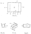
Referring now to FIGS. 2a and 2b, a vertical routing
and storage apparatus 25 according to another embodiment
of the current invention is shown. VRS apparatus 25
comprises an upright member 30 having front and rear
vertical surfaces 32, 34, respectively, a plurality of
front channel assemblies 36 adjustably mounted to the
front vertical face 32, and a plurality of rear channel
assemblies 38 mounted to the rear vertical face 34.
Upright member 30 is adapted for connection to a
supporting frame member (not shown), such as the
distribution frame member 24 (shown in FIG. 1). In the
embodiment shown in FIGS. 2a and 2b, a plurality of
mounting holes 40 are formed in upright member 30 to
facilitate connection to a supporting frame member by
means of bolts, screws or other fasteners, however, it
will be readily apparent that upright member 30 could be
otherwise adapted for connection to a supporting frame as
is known in the art without departing from the scope of
the current invention.
A plurality of vertically oriented slots 42 are
formed in front vertical face 32 of VRS apparatus 25.
Each of the front channel assemblies 36 has a vertical
position which is adjustable through a range of vertical
positions corresponding to the vertical extent of one of
the vertical slots 42. For example, as best seen in FIG.
2a, the front channel assembly designated 36a has a
vertical position, V, which is adjustable through a range
of vertical positions, RV, from the uppermost position
(shown in solid lines) designated as V1, to the lower-most
position (shown in phantom) designated as V2. The range
RV corresponds to the vertical extent of one of the
vertical slots, in this case, either of the slots marked
42a. Each front channel assembly 36 includes two front
side flanges 44 and a first front cross member 46. The
front side flanges 44 are spaced apart from one another
and project outwardly from the front vertical face 32.
The first front cross member 46 is connected to at least
one of the front side flanges 44, thereby defining a front
channel 48 generally bounded by the front side flanges 44
and the first front cross member 46.
The front channel assembly 36 can be adjustably
mounted to the vertical slots 42 of upright member 30 in a
number of ways. In the embodiment shown in FIG. 2a, a
second front cross member 50 is connected between the
front side flanges 44 at the rear side of channel 48. The
second cross member 50 can be adjustably mounted on
upright member 30 by means of various fasteners as is
known in the art. In a preferred embodiment, so-called
cage nuts (not shown) are positioned in vertical slots 42.
The cage nuts have internal threads for receiving a
threaded fastener which is passed through a hole formed in
second front cross member 50. When the fastener is not
tightened, the cage nut can slide in slot 42, thus
allowing the second front cross member 50 to slide
vertically up and down between the top and bottom of the
vertical slot 42. When the fastener is tightened,
however, the cage nut no longer slides in slot 42, rather
it becomes fixed in position, thus securing the front
channel assembly 36 in the desired vertical position. The
vertical position and spacing of front channel assemblies
36 can thus be adjusted to advantageously correspond to
the vertical positions of optical fibers from sources
adjacent to front vertical face 32. Front channel
assemblies are removable and can either not be used or
moved to another pair of slots. Additionally, more than
one channel assembly can be used in a pair of slots.
Referring still to FIGS. 2a and 2b, rear channel
assemblies 38, as best seen in FIG. 2b, are similar to the
front channel assemblies 36, with each rear channel
assembly 38 having two rear side flanges 52 and a rear
cross member 54. The rear side members 52 are spaced
apart from one another and project outwardly from the rear
vertical face 34. Rear cross-member 54 is connected to at
least one of the rear side faces 52, thereby defining a
rear channel 56 bounded by the rear side flanges 52 and
the rear cross member 54. In the preferred embodiment
shown, the rear channel assemblies 38 are fixedly
connected to rear vertical face 34 instead of adjustably
connected because the small number of larger cables
typically routed on the rear side of a distribution frame
do not require precise location of cable management
features as do the jumper cables used on the front side.
As such is may be easier and less costly to manufacture
the back side without accommodating for adjustable
assemblies. Rear channels are removable should they not
be needed or if they interfere with routing of a large
cable or conduit. Further, it will be readily apparent
that VRS apparatus having rear channel assemblies which
are adjustably mounted to the rear vertical face are
within the scope of the current invention. For example,
in one such alternative embodiment similar to the VRS
apparatus 25 shown, vertically adjustable rear channel
assemblies can be provided for mounting to the vertical
slots 42 from the rear vertical face 34, since the
vertical slots 42, while being formed in the front
vertical face 32, can also be accessed from the rear
vertical face 34. This would allow vertically adjustable
channel assemblies to be mounted on both faces of the VRS
apparatus.
Referring still to FIGS. 2a and 2b, to further
enhance the routing and storage capabilities of VRS
apparatus 25, a plurality of spool mounting holes 60 can
be formed in the front vertical face 32 and a storage
spool 62 can be demountably attached to the front vertical
face 32 at one of the spool mounting holes 60. By using
different mounting holes 60, the vertical position of the
spool 62 can be selected. The spool 62 can be demountably
attached to front vertical face 32 using threaded
fasteners such as bolts or screws inserted through the
spool mounting holes 60. In the embodiment shown, four
storage spools 62 are provided. Feed-through holes 63
formed through vertical member 30 can also be provided
allowing cables or fibers (not shown) to be routed from
one side of VRS apparatus 25 to the other. When feed-through
holes 63 are used, rubber or plastic grommets (not
shown) can be positioned in feed-through holes 63 to
protect the fibers from being damaged by the edges of the
hole.
Referring now to FIGS. 3 and 4, a front channel
assembly 36 according to another aspect of the invention
is shown. As previously described, it is desirable to
prevent the excessive bending of optical fibers 29 (shown
in phantom in FIG. 4) as they are routed across the front
side flanges 44 into the front channel 48. In this
aspect, as best seen in FIG. 4, each front side flange 44
further comprises an interior wall 66, which faces the
front channel 48, and an exterior wall 70, which faces
away from the front channel. Interior wall 66 has an
inwardly convex (with respect to the channel 48) surface
68 that is radiused to prevent excessive bending of the
fibers 29 routed there across. In a preferred embodiment
of this aspect, the inwardly convex surface 68 of the
interior wall 66 has, when viewed in cross section (as
shown in FIG. 4), a radius RW within the range of about
0.75 inches. This corresponds to the range of the
permissible bend radius of fiber optic jumper cables.
The inwardly convex surface 68 of interior wall 66
can be formed by directly shaping front side flanges 44
into an inwardly convex cross section. When front side
flanges 44 comprise flat metal parts, however, as is often
the case with optical fiber equipment, the direct shaping
approach can present manufacturing difficulties,
especially when trying to avoid so-called bullet ends on
the inwardly facing side of the flanges. Referring now
specifically to FIG. 4, in another aspect of the current
invention, front side flanges 44 comprise an exterior wall
70 facing away from the channel 48 and a radiused insert
72 connected to the exterior wall. The radiused insert
72, which can be formed of various materials known in the
art including metals and plastics, is preferably formed of
extruded plastic which can be conveniently cut to the
proper length. Radiused insert 72 is attached to exterior
wall 70 thereby forming interior wall 66 having the
desired inwardly convex surface 68. In the embodiment
shown in FIG. 4, radiused inserts 72 have chamfered ends
74 and notches 76 sized to facilitate convenient snap-on
attachment to exterior wall 70, however, other means for
the attachment of radiused inserts 72 to exterior walls
70, including adhesives, screws, bolts and other such
fastenings known in the art, can be used without departing
from the scope of the current invention. It will also be
readily apparent that while the foregoing description
relates specifically to the front side flanges 44 and
front channel assemblies 36 of VRS apparatus 25, it can
further be applied to the rear side flanges 52 and rear
channel assemblies 38 without significant change.
Referring again to FIG. 3, to further facilitate the
routing and storage of optical fibers using VRS apparatus
25, is desirable that the front channel assemblies allow
side access for the positioning of optical fibers in the
channels, rather than requiring them to be threaded in
from one end or the other. In another aspect of the
current invention, the first front cross member 46 further
comprises a first end 78 which is pivotally attached to
one of the front side flanges 44 and a second end 80 which
is releasably securable to the other of the front side
flanges 44. In the embodiment shown, a hinge 79 is
provided for connecting first end 78 to side flange 44.
The position of the front cross member 46 can thus be
moved between an open position (shown in phantom in FIG.
3), which provides side access for the convenient
positioning of optical fibers into the front channel 48,
to a closed position (shown in solid lines in FIG. 3),
providing no side access to the front channel 48 and
increased security to the optical fibers stored within. A
latch mechanism 81, can be provided for releasably
securing second end 80 to the other side flange 44. The
latch mechanism is preferably a swell latch which expands
and contracts, respectively, when an activating lever is
pushed in and pulled out, however other latch mechanisms
known in the art can be used without departing from the
scope of the current invention. While FIG. 3 and the
foregoing description relate specifically to a front
channel assembly 36, it will be readily apparent that the
foregoing description can also be applied to the rear side
flanges 52 and rear channel assemblies 38 without
significant change.
Referring now to FIG. 5, in an alternative embodiment
of the current invention, the front channel assemblies 36
can further comprise a first front cross member 46 having
a fixed end 82 and a free end 84 and a third front cross
member 86 having a fixed end 88 and a free end 90. The
fixed end 82 of the front cross member 46 is connected to
one of the front side flanges 44 and the free end 84
extends towards the other of the front side flanges 44.
The fixed end 88 of the third front cross member 86 is
connected to the other of the front side flanges 44 and
the free end 90 extends generally toward the free end 84
of the first front cross member 46, thereby defining a gap
92 therebetween. Optical fibers (not shown) may be moved
into front channel 48 by passing through the gap 92
between the free ends 84, 90 of the first and third front
cross members 46, 86. The channel assembly 36 of this
embodiment is substantially identical in all other
respects to those of previously discussed embodiments.
Also, while FIG. 5 and the foregoing description relate
specifically to a front channel assembly 36, it will be
readily apparent that the foregoing description can also
be applied to the rear channel assemblies 38 without
significant change.
Optical fiber adaptors and other devices used in
distribution frames such as that shown in FIG. 1 are
typically provided with small removable dust caps to
prevent damage or contamination prior to use. When these
caps are removed by the installer or technician working on
the frame, they are frequently placed on the first
available surface and forgotten. These discarded dust
caps invariably fall to the floor or into openings in the
equipment, forming an unattractive and possibly hazardous
litter. Referring now generally to FIGS. 2a, 2b, 3 and 4
and specifically to FIGS. 6a-6c, in another aspect of the
current invention, the VRS apparatus 25 further comprises
a dust cap storage cup 100 which is releasably mounted to
one of the front side flanges 44. The dust cap storage
cup 100 includes a storage cavity 102 and a connecting
mechanism 104. The storage cavity 102 provides a place
where dust caps can be advantageously stored for ready
access by personnel working on nearby equipment and to
prevent the caps from falling into equipment or onto the
floor. The connecting mechanism 104 releasably secures
the cup 100 to the front side flange 44. If necessary, a
compatible connecting mechanism 98 can be provided on
front side flanges 44 to cooperate with connecting
mechanism 104 of the cup. For example, in the embodiment
shown in FIGS. 2, 3, 4, and 6a-6c (best seen in FIGS. 3
and 4), flange connecting mechanism 98 comprises holes 106
formed in the exterior wall 70 of front side flanges 44
and cup connecting mechanism 104 comprises pegs 108
adapted for frictional fit within holes 106. While the
peg-in-hole connecting mechanism used in the current
embodiment is simple to manufacture and use, other
connecting mechanisms known in the art, including clips,
hangers, hook and loop material, and releasable adhesives
can also be used to connect the cup 100 to the channel
assemblies 36. Alternately, the flange connecting
mechanism 98 can be used alone to releasably mount the cup
100 if appropriate. While the foregoing description
relates specifically to a cup 100 for mounting on a front
channel assembly 36, it will be readily apparent that the
cup 100 can also be mounted to the rear channel
assemblies 38 without significant change.
Although several embodiments of the present
invention have been illustrated in the accompanying
drawings and described in the foregoing Detailed
Description, it will be understood that the invention is
not limited to the embodiments disclosed, but is capable
of numerous rearrangements, modifications and substitution
of parts and elements without departing from the scope and
spirit of the invention.