EP0846915A1 - Inner room light - Google Patents
Inner room light Download PDFInfo
- Publication number
- EP0846915A1 EP0846915A1 EP97104417A EP97104417A EP0846915A1 EP 0846915 A1 EP0846915 A1 EP 0846915A1 EP 97104417 A EP97104417 A EP 97104417A EP 97104417 A EP97104417 A EP 97104417A EP 0846915 A1 EP0846915 A1 EP 0846915A1
- Authority
- EP
- European Patent Office
- Prior art keywords
- light
- interior
- lamp
- light guide
- light source
- Prior art date
- Legal status (The legal status is an assumption and is not a legal conclusion. Google has not performed a legal analysis and makes no representation as to the accuracy of the status listed.)
- Granted
Links
- 238000010168 coupling process Methods 0.000 claims description 13
- 238000005859 coupling reaction Methods 0.000 claims description 13
- 230000001902 propagating effect Effects 0.000 claims 2
- 230000000694 effects Effects 0.000 abstract description 6
- 230000004313 glare Effects 0.000 description 20
- 230000004907 flux Effects 0.000 description 11
- 230000008878 coupling Effects 0.000 description 8
- 239000000463 material Substances 0.000 description 6
- 230000005855 radiation Effects 0.000 description 6
- 238000010586 diagram Methods 0.000 description 5
- 238000005516 engineering process Methods 0.000 description 5
- 230000003287 optical effect Effects 0.000 description 4
- 210000003128 head Anatomy 0.000 description 3
- 239000004033 plastic Substances 0.000 description 3
- 229920003023 plastic Polymers 0.000 description 3
- 239000002985 plastic film Substances 0.000 description 3
- 229920006255 plastic film Polymers 0.000 description 3
- 230000011514 reflex Effects 0.000 description 3
- 239000004809 Teflon Substances 0.000 description 2
- 229920006362 Teflon® Polymers 0.000 description 2
- 239000004973 liquid crystal related substance Substances 0.000 description 2
- 239000013307 optical fiber Substances 0.000 description 2
- 229920003229 poly(methyl methacrylate) Polymers 0.000 description 2
- 239000004926 polymethyl methacrylate Substances 0.000 description 2
- 239000012790 adhesive layer Substances 0.000 description 1
- 238000011161 development Methods 0.000 description 1
- 230000018109 developmental process Effects 0.000 description 1
- 230000004438 eyesight Effects 0.000 description 1
- 239000000835 fiber Substances 0.000 description 1
- 210000001061 forehead Anatomy 0.000 description 1
- 239000011521 glass Substances 0.000 description 1
- 230000003760 hair shine Effects 0.000 description 1
- 239000010410 layer Substances 0.000 description 1
- 238000004519 manufacturing process Methods 0.000 description 1
- 230000001404 mediated effect Effects 0.000 description 1
- 230000036651 mood Effects 0.000 description 1
- 239000011022 opal Substances 0.000 description 1
- 210000001328 optic nerve Anatomy 0.000 description 1
- 239000007787 solid Substances 0.000 description 1
- 238000001228 spectrum Methods 0.000 description 1
- 239000010409 thin film Substances 0.000 description 1
- 230000004304 visual acuity Effects 0.000 description 1
- 230000000007 visual effect Effects 0.000 description 1
Images


Classifications
-
- G—PHYSICS
- G02—OPTICS
- G02B—OPTICAL ELEMENTS, SYSTEMS OR APPARATUS
- G02B6/00—Light guides; Structural details of arrangements comprising light guides and other optical elements, e.g. couplings
- G02B6/0001—Light guides; Structural details of arrangements comprising light guides and other optical elements, e.g. couplings specially adapted for lighting devices or systems
- G02B6/0011—Light guides; Structural details of arrangements comprising light guides and other optical elements, e.g. couplings specially adapted for lighting devices or systems the light guides being planar or of plate-like form
- G02B6/0013—Means for improving the coupling-in of light from the light source into the light guide
- G02B6/0023—Means for improving the coupling-in of light from the light source into the light guide provided by one optical element, or plurality thereof, placed between the light guide and the light source, or around the light source
- G02B6/0031—Reflecting element, sheet or layer
-
- F—MECHANICAL ENGINEERING; LIGHTING; HEATING; WEAPONS; BLASTING
- F21—LIGHTING
- F21S—NON-PORTABLE LIGHTING DEVICES; SYSTEMS THEREOF; VEHICLE LIGHTING DEVICES SPECIALLY ADAPTED FOR VEHICLE EXTERIORS
- F21S6/00—Lighting devices intended to be free-standing
- F21S6/002—Table lamps, e.g. for ambient lighting
-
- F—MECHANICAL ENGINEERING; LIGHTING; HEATING; WEAPONS; BLASTING
- F21—LIGHTING
- F21S—NON-PORTABLE LIGHTING DEVICES; SYSTEMS THEREOF; VEHICLE LIGHTING DEVICES SPECIALLY ADAPTED FOR VEHICLE EXTERIORS
- F21S8/00—Lighting devices intended for fixed installation
- F21S8/02—Lighting devices intended for fixed installation of recess-mounted type, e.g. downlighters
- F21S8/026—Lighting devices intended for fixed installation of recess-mounted type, e.g. downlighters intended to be recessed in a ceiling or like overhead structure, e.g. suspended ceiling
-
- F—MECHANICAL ENGINEERING; LIGHTING; HEATING; WEAPONS; BLASTING
- F21—LIGHTING
- F21V—FUNCTIONAL FEATURES OR DETAILS OF LIGHTING DEVICES OR SYSTEMS THEREOF; STRUCTURAL COMBINATIONS OF LIGHTING DEVICES WITH OTHER ARTICLES, NOT OTHERWISE PROVIDED FOR
- F21V17/00—Fastening of component parts of lighting devices, e.g. shades, globes, refractors, reflectors, filters, screens, grids or protective cages
- F21V17/02—Fastening of component parts of lighting devices, e.g. shades, globes, refractors, reflectors, filters, screens, grids or protective cages with provision for adjustment
-
- F—MECHANICAL ENGINEERING; LIGHTING; HEATING; WEAPONS; BLASTING
- F21—LIGHTING
- F21V—FUNCTIONAL FEATURES OR DETAILS OF LIGHTING DEVICES OR SYSTEMS THEREOF; STRUCTURAL COMBINATIONS OF LIGHTING DEVICES WITH OTHER ARTICLES, NOT OTHERWISE PROVIDED FOR
- F21V5/00—Refractors for light sources
- F21V5/002—Refractors for light sources using microoptical elements for redirecting or diffusing light
-
- F—MECHANICAL ENGINEERING; LIGHTING; HEATING; WEAPONS; BLASTING
- F21—LIGHTING
- F21V—FUNCTIONAL FEATURES OR DETAILS OF LIGHTING DEVICES OR SYSTEMS THEREOF; STRUCTURAL COMBINATIONS OF LIGHTING DEVICES WITH OTHER ARTICLES, NOT OTHERWISE PROVIDED FOR
- F21V7/00—Reflectors for light sources
- F21V7/0008—Reflectors for light sources providing for indirect lighting
- F21V7/0016—Reflectors for light sources providing for indirect lighting on lighting devices that also provide for direct lighting, e.g. by means of independent light sources, by splitting of the light beam, by switching between both lighting modes
-
- F—MECHANICAL ENGINEERING; LIGHTING; HEATING; WEAPONS; BLASTING
- F21—LIGHTING
- F21V—FUNCTIONAL FEATURES OR DETAILS OF LIGHTING DEVICES OR SYSTEMS THEREOF; STRUCTURAL COMBINATIONS OF LIGHTING DEVICES WITH OTHER ARTICLES, NOT OTHERWISE PROVIDED FOR
- F21V7/00—Reflectors for light sources
- F21V7/005—Reflectors for light sources with an elongated shape to cooperate with linear light sources
-
- F—MECHANICAL ENGINEERING; LIGHTING; HEATING; WEAPONS; BLASTING
- F21—LIGHTING
- F21V—FUNCTIONAL FEATURES OR DETAILS OF LIGHTING DEVICES OR SYSTEMS THEREOF; STRUCTURAL COMBINATIONS OF LIGHTING DEVICES WITH OTHER ARTICLES, NOT OTHERWISE PROVIDED FOR
- F21V7/00—Reflectors for light sources
- F21V7/22—Reflectors for light sources characterised by materials, surface treatments or coatings, e.g. dichroic reflectors
- F21V7/24—Reflectors for light sources characterised by materials, surface treatments or coatings, e.g. dichroic reflectors characterised by the material
-
- F—MECHANICAL ENGINEERING; LIGHTING; HEATING; WEAPONS; BLASTING
- F21—LIGHTING
- F21V—FUNCTIONAL FEATURES OR DETAILS OF LIGHTING DEVICES OR SYSTEMS THEREOF; STRUCTURAL COMBINATIONS OF LIGHTING DEVICES WITH OTHER ARTICLES, NOT OTHERWISE PROVIDED FOR
- F21V7/00—Reflectors for light sources
- F21V7/22—Reflectors for light sources characterised by materials, surface treatments or coatings, e.g. dichroic reflectors
- F21V7/28—Reflectors for light sources characterised by materials, surface treatments or coatings, e.g. dichroic reflectors characterised by coatings
-
- G—PHYSICS
- G02—OPTICS
- G02B—OPTICAL ELEMENTS, SYSTEMS OR APPARATUS
- G02B6/00—Light guides; Structural details of arrangements comprising light guides and other optical elements, e.g. couplings
- G02B6/0001—Light guides; Structural details of arrangements comprising light guides and other optical elements, e.g. couplings specially adapted for lighting devices or systems
- G02B6/0011—Light guides; Structural details of arrangements comprising light guides and other optical elements, e.g. couplings specially adapted for lighting devices or systems the light guides being planar or of plate-like form
- G02B6/0033—Means for improving the coupling-out of light from the light guide
- G02B6/005—Means for improving the coupling-out of light from the light guide provided by one optical element, or plurality thereof, placed on the light output side of the light guide
- G02B6/0053—Prismatic sheet or layer; Brightness enhancement element, sheet or layer
-
- F—MECHANICAL ENGINEERING; LIGHTING; HEATING; WEAPONS; BLASTING
- F21—LIGHTING
- F21V—FUNCTIONAL FEATURES OR DETAILS OF LIGHTING DEVICES OR SYSTEMS THEREOF; STRUCTURAL COMBINATIONS OF LIGHTING DEVICES WITH OTHER ARTICLES, NOT OTHERWISE PROVIDED FOR
- F21V11/00—Screens not covered by groups F21V1/00, F21V3/00, F21V7/00 or F21V9/00
- F21V11/08—Screens not covered by groups F21V1/00, F21V3/00, F21V7/00 or F21V9/00 using diaphragms containing one or more apertures
- F21V11/14—Screens not covered by groups F21V1/00, F21V3/00, F21V7/00 or F21V9/00 using diaphragms containing one or more apertures with many small apertures
-
- F—MECHANICAL ENGINEERING; LIGHTING; HEATING; WEAPONS; BLASTING
- F21—LIGHTING
- F21V—FUNCTIONAL FEATURES OR DETAILS OF LIGHTING DEVICES OR SYSTEMS THEREOF; STRUCTURAL COMBINATIONS OF LIGHTING DEVICES WITH OTHER ARTICLES, NOT OTHERWISE PROVIDED FOR
- F21V14/00—Controlling the distribution of the light emitted by adjustment of elements
- F21V14/02—Controlling the distribution of the light emitted by adjustment of elements by movement of light sources
-
- F—MECHANICAL ENGINEERING; LIGHTING; HEATING; WEAPONS; BLASTING
- F21—LIGHTING
- F21V—FUNCTIONAL FEATURES OR DETAILS OF LIGHTING DEVICES OR SYSTEMS THEREOF; STRUCTURAL COMBINATIONS OF LIGHTING DEVICES WITH OTHER ARTICLES, NOT OTHERWISE PROVIDED FOR
- F21V2200/00—Use of light guides, e.g. fibre optic devices, in lighting devices or systems
- F21V2200/20—Use of light guides, e.g. fibre optic devices, in lighting devices or systems of light guides of a generally planar shape
-
- F—MECHANICAL ENGINEERING; LIGHTING; HEATING; WEAPONS; BLASTING
- F21—LIGHTING
- F21W—INDEXING SCHEME ASSOCIATED WITH SUBCLASSES F21K, F21L, F21S and F21V, RELATING TO USES OR APPLICATIONS OF LIGHTING DEVICES OR SYSTEMS
- F21W2106/00—Interior vehicle lighting devices
-
- F—MECHANICAL ENGINEERING; LIGHTING; HEATING; WEAPONS; BLASTING
- F21—LIGHTING
- F21W—INDEXING SCHEME ASSOCIATED WITH SUBCLASSES F21K, F21L, F21S and F21V, RELATING TO USES OR APPLICATIONS OF LIGHTING DEVICES OR SYSTEMS
- F21W2131/00—Use or application of lighting devices or systems not provided for in codes F21W2102/00-F21W2121/00
- F21W2131/40—Lighting for industrial, commercial, recreational or military use
- F21W2131/402—Lighting for industrial, commercial, recreational or military use for working places
-
- F—MECHANICAL ENGINEERING; LIGHTING; HEATING; WEAPONS; BLASTING
- F21—LIGHTING
- F21Y—INDEXING SCHEME ASSOCIATED WITH SUBCLASSES F21K, F21L, F21S and F21V, RELATING TO THE FORM OR THE KIND OF THE LIGHT SOURCES OR OF THE COLOUR OF THE LIGHT EMITTED
- F21Y2103/00—Elongate light sources, e.g. fluorescent tubes
- F21Y2103/30—Elongate light sources, e.g. fluorescent tubes curved
- F21Y2103/33—Elongate light sources, e.g. fluorescent tubes curved annular
-
- F—MECHANICAL ENGINEERING; LIGHTING; HEATING; WEAPONS; BLASTING
- F21—LIGHTING
- F21Y—INDEXING SCHEME ASSOCIATED WITH SUBCLASSES F21K, F21L, F21S and F21V, RELATING TO THE FORM OR THE KIND OF THE LIGHT SOURCES OR OF THE COLOUR OF THE LIGHT EMITTED
- F21Y2105/00—Planar light sources
-
- F—MECHANICAL ENGINEERING; LIGHTING; HEATING; WEAPONS; BLASTING
- F21—LIGHTING
- F21Y—INDEXING SCHEME ASSOCIATED WITH SUBCLASSES F21K, F21L, F21S and F21V, RELATING TO THE FORM OR THE KIND OF THE LIGHT SOURCES OR OF THE COLOUR OF THE LIGHT EMITTED
- F21Y2113/00—Combination of light sources
-
- F—MECHANICAL ENGINEERING; LIGHTING; HEATING; WEAPONS; BLASTING
- F21—LIGHTING
- F21Y—INDEXING SCHEME ASSOCIATED WITH SUBCLASSES F21K, F21L, F21S and F21V, RELATING TO THE FORM OR THE KIND OF THE LIGHT SOURCES OR OF THE COLOUR OF THE LIGHT EMITTED
- F21Y2113/00—Combination of light sources
- F21Y2113/20—Combination of light sources of different form
-
- G—PHYSICS
- G02—OPTICS
- G02B—OPTICAL ELEMENTS, SYSTEMS OR APPARATUS
- G02B6/00—Light guides; Structural details of arrangements comprising light guides and other optical elements, e.g. couplings
- G02B6/0001—Light guides; Structural details of arrangements comprising light guides and other optical elements, e.g. couplings specially adapted for lighting devices or systems
- G02B6/0011—Light guides; Structural details of arrangements comprising light guides and other optical elements, e.g. couplings specially adapted for lighting devices or systems the light guides being planar or of plate-like form
- G02B6/0033—Means for improving the coupling-out of light from the light guide
- G02B6/0035—Means for improving the coupling-out of light from the light guide provided on the surface of the light guide or in the bulk of it
- G02B6/0045—Means for improving the coupling-out of light from the light guide provided on the surface of the light guide or in the bulk of it by shaping at least a portion of the light guide
- G02B6/0046—Tapered light guide, e.g. wedge-shaped light guide
Definitions
- the invention relates to an interior light according to the preamble of claim 1.
- a major problem of interior lighting in particular When it comes to office lighting, on the one hand a surface of the interior to be illuminated is preferred uniform, but at least sufficient illuminance to achieve, but at the same time - and that applies especially for workplaces, especially for VDU workstations - unwanted glare from the selected Exclude lighting. It is particularly critical the reflex glare caused by light reflections Work surfaces or work equipment, such as. B. a monitor.
- EP-B1-0 665 936 An example of such a solution is known from EP-B1-0 665 936, in which a luminaire with an elongated illuminant and reflectors is described, which is extend like a bird's wing " into the vicinity of ceiling elements to which the lamp is attached.
- the design of the reflector surfaces as such means that this lamp has a relatively large light exit surface compared to a mirror louvre Light is emitted to the ceiling surface surrounding the luminaire and, with high luminaire efficiency, a pleasant, calm and daylight-like lighting effect results from a luminaire that can also be used in rooms with VDU workstations.
- the luminaire efficiency is such Interior light not only on the type of decoupling of the in the light guide plate transported light but also from the coupling of this light into the light guide plate significantly influenced.
- a multilayer plate is used as the coupling element proposed whose layers for targeted Direction of light in the beam direction of that radiated by the light source Light optically become denser. That means, apart from the technological effort, inevitably Multiple reflections of the light when coupling in with corresponding light losses.
- a flat reflector arranged roof-shaped above the light source suggested. While this suggestion is simpler too realize, but, as has been shown, does not lead to satisfactory results Results.
- each microprism has at least one sidewall that is in one predetermined angle vertical to the surface of the light guide plate is inclined so that from the light guide plate in the microprism light entering this inclined side wall is reflected and substantially perpendicular to that Light exit surface of the microprisms emerges.
- the present invention has for its object a Interior light of the type mentioned to create the in terms of luminaire efficiency and compliance glare control conditions with conventional luminaire types, such as B. Grid mirror lights, quite comparable but is based on the principle of a light source radiated light, using an optical fiber compared to conventional interior lights relatively large light-emitting surface evenly and to steer with good efficiency and in compliance the known anti-glare conditions.
- the light-emitting surface here the light exit surface of the lamp, not only with a good one Illuminate efficiency as evenly as possible, but in addition to direct the light radiation so that the dimming conditions defined for such lighting, with regard to the longitudinal and transverse glare control of the luminaire, but above all also with regard to a possible reflected glare be respected.
- the absolute dimension of the individual is less important Elements ("elevations") of the prism structure coupling out the light than on their design and location of the reflection surfaces, to achieve the desired light distribution
- Elevations Elements of the prism structure coupling out the light than on their design and location of the reflection surfaces
- FIG 1 and Figure 2 is a schematic representation in each case a three-dimensional view or a cross section shown for an interior light, whose characteristic external feature in a distinctly flat design lies.
- the light source of this interior light is in this Example one with its longitudinal axis in the central plane of the Luminaire lying elongated lamp 1 used, the concentric a main reflector 2 surrounding it on its axis assigned.
- This main reflector 2 consists of two Half-shells 21 and 22, which are circular in cross-section trained and - based on the lamp - above or are arranged below the lamp 1.
- the two half shells 21, 22 of the main reflector 2 are facing the lamp 1 Completely diffusely reflective inside.
- the light guide plates 3 have exactly parallel and flat tops or Bottom pages consist of a transparent as possible Material, such as glass or a plastic.
- a transparent as possible Material such as glass or a plastic.
- Plastic material for example, offers undyed polymethyl methacrylate (PMMA) because of this in lighting technology is already widely used. Of course other materials can also be used, if they have the required light-guiding properties.
- PMMA polymethyl methacrylate
- the end faces of the light guide plates facing away from the lamp 1 3 are covered with a flat reflector strip 4, its directly on the front of each Light guide plate 3 attached inner surface also possible is completely diffusely reflective.
- a suitable material is made of white colored Teflon existing tape.
- the reflector strips 4 are above all on the face opposite the light entry side the light guide plates 3 are functionally important. It is advantageous but it also, the other end faces of the light guide plates to cover.
- a plastic film is applied directly to the undersides of the light guide plates 3 as a light-coupling element, which extends from the outer edges of the light guide plates 3 to close to the main reflector 2.
- This plastic film has a microprism structure and is therefore referred to below as prism 5.
- Materials of this type are under the trademark Spectra Vue offered by AlliedSignal Inc. on the market in particular for the backlighting of liquid crystal displays.
- a prism structure is to be used here for the interior lighting, in which the inclination angles of the microprisms are adapted to the desired light distribution curve.
- the interior light described a pronounced flat design, which in particular also due to the use of 16 mm diameter fluorescent lamps available today (inconsistently referred to as T5 or T16 lamps) will, as will be explained later.
- the lamp diameter determines also approximately the thickness of the light guide plates 3, the Thickness to width ratio - seen in cross-sectional direction - e.g. Is 1:10.
- Essential for the function of the in Figure 1 and Figure 2 interior light is initially the light-generating unit, consisting of the lamp 1 and the concentrically surrounding main reflector 2.
- the inner surfaces of the two half-shells facing the lamp 1 21 and 22 as ideally as possible diffusely reflecting are trained and for this purpose, for example just like the reflector strips 4 with white colored Teflon coated, form the lamp 1 and the main reflector 2 a lighting unit, approximately corresponds to a Lambert radiator.
- FIG. 3 shows the luminous intensity distribution curve of this lighting unit, consisting of lamp 1 and main reflector 2 in the so-called C0-180 ° plane, ie here in the transverse plane perpendicular to the longitudinal axis of lamp 1.
- this circle is deformed approximately elliptically.
- this light distribution curve shown in FIG. 3 illustrates that light is not directed into the light guide plates 3 arranged on both sides of the lamp 1, but is radiated in as diffusely as possible.
- Beam path of the coupled into the light guide plates 3 Light which is exemplified by two typical partial beams S1 or S2 is indicated.
- the first sub-beam S1 is after the refractive passage through the lamp 1 facing End face of the light guide plate 3 on its top and bottom totally reflected several times. He reaches that of Lamp 1 remote outer face of the light guide plate 3, where it is omnidirectional on the corresponding reflector strip 4 reflected back into the light guide plate 3 becomes.
- the second sub-beam S2 illustrates that due to the diffuse Beam characteristic of lamp 1 and main reflector 2 existing light emitting unit a certain partial luminous flux already from the bottom of the light guide plate 3 can emerge without the light rays of this partial luminous flux previously total reflections in the light guide plate 3 experienced.
- the individual rays of the emerging from the light guide plate 3 Light here for example the partial beams S1 or S2, are deflected by the prism 5.
- the present one Embodiment of the prism 5 in particular with regard to the angle of inclination of the microprisms is adjusted so that they has a glare-limiting effect.
- Figure 4 one corresponding to the representation of Figure 3 Diagram, are for explaining this glare limitation the light distribution curves which now concern the interior light as a unit for the two perpendicular to each other C0-180 ° or C90-270 ° planes shown. From the comparison of the two diagrams of Figure 3 and Figure 4 is the light-guiding function of the light guide plates 3 in connection with the corresponding prismatics 5 clearly.
- the corresponding Light distribution curves are in solid or broken lines.
- the two curve branches of the Demonstrate light distribution curves for the lower half space the well-focused radiation characteristics of the interior light with a clear cross glare control, but especially also an excellent longitudinal glare control of the lamp. Lots conventional interior lights meet these two, in particular essential for lighting workplaces Conditions not equally in both directions.
- FIG. 4 also shows another special feature of the interior light, that has not yet been mentioned.
- the described Basic shape of the interior light should be in itself no significant luminous flux in the upper half-space emerge. If so, the light distribution curves shown in Figure 4 accordingly, however the case is, it is this is due to a training of the interior light described.
- the main reflector 2 of the interior light without his limit the basic function as a diffuse reflector, also to be partially translucent.
- the in Figure 4 shown light distribution curves is an interior light on which the upper half shell 21 of the Main reflector 2 partially translucent, here in the form of a Opal shell, is formed.
- Another way with similar The lighting effect is this upper one To produce half-shell 21 of the main reflector 2 from a screen plate. In principle, the same applies to the lower one Half-shell 22, if this is desired because of the optical effect would be without the described function of To significantly impair or leave the basic form.
- FIG. 6 shows another possible embodiment shown for the interior light
- the one relating to the luminaire center plane is mirror-symmetrical Luminaire structure with one 1 '' lamp and one assigned main reflector 2 '' as one of two light-coupling Shows units to which only one-sided a single light guide plate 3 is assigned.
- the light is coupled in only one embodiment Direction, but basically the same principle of operation this embodiment also corresponds to that of FIGS 4 described basic shape of the interior light. Repetitions superfluous to the lighting function of this embodiment yourself.
- the two other main reflectors 2 '' each not completely form the assigned lamp 1 '', but to leave a gap open on the top an indirect luminous flux component directed against the ceiling can leak.
- This example also shows that it is expedient, such a gap near the front edge of the to assign assigned light guide plate 3 to the function of the main reflector as an approximate Lambert radiator essentially to ensure. In this case, too Indoor light as direct / indirect light, as schematic by arrows for the upwards or downwards Luminous flux components is specified.
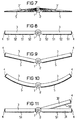
- FIGS. 7 to 11 show further embodiments for Indoor lights with one each with respect to two light guide plates 3 centrally arranged elongated light source 1 corresponding to the basic form shown in Figures 1 and 2.
- Structure and arrangement of the light-emitting unit from the light source 1 and the main reflector 2 with two half shells 21 and 22 is analogous to the embodiment of Figures 1 and 2 chosen so that for the subsequent Embodiments also the corresponding ones already The details described apply and none here Repetition is required.
- FIG. 1 In the cross section shown schematically in FIG Another embodiment of an interior light are both sides of the light source 1 and the main reflector 2 with its half-shells 21 and 22 arranged light guide plates 3 'wedge-shaped.
- the angle of inclination between the bottom and top surface of the light guide plates 3 ' can be, as in Figure 7 schematically by a distribution indicated by rays of light, the direction of light in Affect the direction of propagation in the light guide plates 3 '.
- the exemplary embodiment according to FIG. 1 and 2 do not contradict the original direction of propagation partial beams reflected back. Except from the even flatter, purely functional in design luminaire design there are possibilities here to further improve the operating efficiency of the lamp.
- FIG. 8 shows a further embodiment for an interior light shown at first sight of the embodiment corresponds to Figure 1 or 2.
- the light coupling-out prism 5 into individual prism areas 51 or 52 divided.
- These prismatic areas 51 and 52 are in terms of their light-coupling surfaces designed in such a way that they each have different light Radiate light distribution.
- the one prismatic areas 51 formed such that they a preferably narrow-beam light emission characteristic own, while on the other hand the second prismatic areas 52 a predominantly wide-angle light emission characteristic exhibit.
- each with different Light distribution curve can be zonal as well Realize large-area lighting solutions and therefore different ones Create lighting moods.
- Figure 9 shows a further embodiment of an interior light.
- these two Light guide plates 3 by a predetermined angle in the Vertical employed. If the light guide plates 3 in relation hinge-like arranged on the longitudinal axis of the lamp are, this angle of attack is not fixed, but even adjustable.
- the light coupling-out prism 5 is a predetermined one Light distribution curve with a defined main beam direction owns, this is the main emission direction when the light guide plates 3 are turned on by a predetermined one Angle also by this angle of attack from the vertical pivoted outwards.
- predominantly narrow beam light emission characteristic of Prismatics 5 can be so with increasing angle of attack
- Light guide plates 3 a light emission of the entire interior light achieve that always with increasing angle of attack becomes more wide-angle.
- Figure 10 is also an embodiment in cross section shown the interior light, in which the light guide plates 3 - in contrast to all of the previously described embodiments - Arched outward from the center axis of the lamp are.
- the light guide plates 3 made of a plastic material are such a curved cross-sectional profile to realize the light guide plates 3 with simple means.
- the prismatics 5 also exist as required from a thin plastic film with sufficient Elasticity, so that it is mechanically easy the underside of the light guide plates 3 immediately set leave without loss of efficiency of the interior light to have to put up with. From a lighting point of view, this is Embodiment of an interior light shown in FIG with swing-like curved light guide plates 3 one Alternative to the embodiment of Figure 9.
- Figure 11 is an embodiment of the interior light shown, in which the flat light guide plates 3, in Seen longitudinal direction of the lamp, divided into sections are, so that, for example, one between two end faces End regions 31 of the light guide plates 3 centrally arranged Middle area 32 individually compared to these forehead areas 31 can be adjusted by a predetermined angle. If you assume from that the frontally arranged, horizontally aligned Subregions 31 of the light guide plates 3 light-coupling Prismatics 5 with light-distributing properties wear, as above for that with reference to Figures 1 and 2 described embodiments have been explained, so forms also the embodiment shown in FIG. 11 initially an interior light with longitudinal and cross glare control.
- This lamp can be made into a lighting system, if you now for the extendable central areas 32 Printed circuit boards 3 selects a prism 51, whose light emission characteristic non-glare limited wide beam, but is mainly narrow beam. In this case it works the central region 31 to be exhibited according to the embodiment Figure 11 similar to a conventional radiator with a strongly bundled light distribution, which directly into one glare-limited interior light is integrated. With the In this way, the embodiment shown in FIG. 11 can be used in addition to a general limited lighting accent put.
- Embodiments was an elongated as the light source 1 Lamp, preferably a fluorescent lamp, if possible based on a small diameter.
- the two in figure Differentiate between illustrated embodiments 12 and 13 respectively itself, otherwise the described lighting concept also used here.
- a circular lamp is shown in a half section, whose light source 1 '' 'is designed as an annular lamp is.
- This light source 1 '' ' encloses one to it aligned light guide plate designed as a circular disk 3 '', which in turn is one in in this case also a disc-shaped prism 5 'carries.
- the properties set out in the embodiments convey the Light guide plate 3 '' over its circumferential surface from the neighboring one Light source 1 'coupled light in radial Direction and shines downwards over the prismatic 5 '.
- the radiation characteristic is preferred this prism 5 'mainly narrow beam, so that the so on an illuminated surface under the lamp Luminous flux component is focused zonally.
- the Round lamp shown in Figure 12 concentric to the light source 1 '' 'arranged, a roof reflector 6, the Cross-sectional profile, for example in the form of an approximate Involute to the light source 1 'is formed.
- a counter reflector 7 is provided. This is in cross section formed in the shape of a half-shell and the light source 1 '' 'covering from below against the light exit opening arranged.
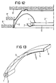
- FIG. 13 schematically illustrates that the underlying concept also realized in the form of a table lamp can be.
- the light source is 1, surrounded by the main reflector 2, arranged in the foot part of the lamp, as shown schematically.
- a lamp with a relatively short burner as the light source used.
- Light guide plate 3 in the direction of the head of the table lamp transported.
- FIG. 13 shows that the light guide plate 3 in the form of a curved rectangular rod is trained.
- other embodiments are also conceivable.
- the head side End face of the light guide plate 3 is again through a Reflector 4 covered in the form of a thin film, the the inside of the light guide plate 3 is reflective is trained.
- the light decoupling prism 5 arranged in the head part of the table lamp of Figure 13 .
Abstract
Description
Die Erfindung bezieht sich auf eine Innenraumleuchte gemäß
dem Oberbegriff des Patentanspruches 1.The invention relates to an interior light according to
the preamble of
Ein wesentliches Problem der Innenraumbeleuchtung, insbesondere bei der Bürobeleuchtung besteht darin, einerseits auf einer zu beleuchtenden Fläche des Innenraumes eine Vorzugsweise gleichmäßige, jedenfalls aber ausreichende Beleuchtungsstärke zu erzielen, gleichzeitig aber - und das gilt insbesondere für Arbeitsplätze, vor allem auch für Bildschirmarbeitsplätze - eine unerwünschte Blendung durch die gewählte Beleuchtung auszuschließen. Besonders kritisch ist dabei die Reflexblendung, hervorgerufen durch Lichtreflexionen auf Arbeitsflächen oder Arbeitsmitteln, wie z. B. einem Monitor.A major problem of interior lighting, in particular When it comes to office lighting, on the one hand a surface of the interior to be illuminated is preferred uniform, but at least sufficient illuminance to achieve, but at the same time - and that applies especially for workplaces, especially for VDU workstations - unwanted glare from the selected Exclude lighting. It is particularly critical the reflex glare caused by light reflections Work surfaces or work equipment, such as. B. a monitor.
Da diese Problemstellung bekannt ist, wurde dazu auch bereits eine Vielzahl von Lösungsvorschlägen gemacht. Gemeinsam ist diesen bekannten Lösungen, eine entsprechende Innenraumleuchte so auszugestalten, daß einerseits ihre Leuchtdichte trotz hoher Lichtstärke einen vorgegebenen Wert nicht übersteigt und ferner die Lichtstärkeverteilung der Leuchte durch gezielte Lichtlenkung so ausgebildet ist, daß dabei ein vorgegebener Abblendwinkel γ, gemessen gegen die Vertikale, eingehalten wird. Ein typisches Beispiel für einen Leuchtentyp, mit dem diese Bedingungen für eine Querentblendung,mit gewissen Einschränkungen auch eine Längsentblendung zu erfüllen sind, ist die Spiegelrasterleuchte. Deren lichttechnisches Prinzip besteht - bezogen auf den hier vorliegenden Fall betrachtet - darin, eine möglichst große Lichtmenge durch eine relativ kleine Lichtaustrittsöffnung so gelenkt abzustrahlen, daß die genannten Bedingungen noch eingehalten sind. Wesentlichen Anteil an der Lichtlenkung hat dabei das aufwendige und in seiner Herstellung teure Spiegelraster. Since this problem is known, this has already been done made a variety of proposed solutions. Is common these known solutions, a corresponding interior light To be designed so that on the one hand their luminance despite high light intensity does not exceed a predetermined value and also the luminous intensity distribution of the lamp through targeted Light control is designed so that a predetermined Anti-glare angle γ, measured against the vertical, maintained becomes. A typical example of a type of luminaire, with which these conditions for cross-glare, with certain Restrictions also apply to longitudinal glare control is the mirror louvre. Their lighting technology The principle exists - in relation to the present case - in the greatest possible amount of light through a to direct the relatively small light exit opening in such a way that the conditions mentioned are still met. Essentially The elaborate part of the light control is involved and expensive mirror grids in its manufacture.
Wenn man von den sogenannten Indirektleuchten absieht, die das Licht vor allem gegen die Raumdecke und gegebenenfalls auch oberhalb des normalen Sichtbereiches liegende Wandteile abstrahlen, besteht eine weitere Möglichkeit, den genannten Abstrahlungsbedingungen zu genügen, darin, die der zu beleuchtenden Fläche zugekehrte Lichtaustrittsöffnung der Inneraumleuchte zu vergrößern.If you ignore the so-called indirect lights, the the light especially against the ceiling and if necessary also wall parts above the normal field of vision radiate, there is another possibility, the aforementioned To meet radiation conditions, that of those to be illuminated Surface facing light exit opening of the interior light to enlarge.
Aus EP-B1-0 665 936 ist ein Beispiel für einen derartigen Lösungsansatz
bekannt, in der eine Leuchte mit langgestrecktem
Leuchtmittel und Reflektoren beschrieben ist, die sich
![]()
![]()
Aus EP-B1-0 371 073 ist ferner eine Vorrichtung mit einer Lichtleiterplatte bekannt, in der Licht - ausgehend von einer Lichtquelle - mit Komponenten parallel zu den großen Plattenflächen geführt wird und aus Erhebungen austritt, die auf der Oberfläche einer dieser Plattenflächen mit einer dazwischen aufgebrachten Haftschicht dicht an dicht angeordnet sind sowie nach Höhe und Breite in der Größenordnung zwischen 0,5 und 0,001 mm liegen. Dabei wird davon ausgegangen, daß bei Erhebungen dieser Größenordnung deren abstrahlende Fläche in der Projektion auf einen Betrachter etwa mit der Untergrenze des Auflösungsvermögens des menschlichen Auges zusammenfällt. Aus dieser optischen Überlegung wird abgeleitet, daß die gesamte abstrahlende Fläche gleichmäßig hell erscheint. From EP-B1-0 371 073 a device with a Light guide plate known in the light - starting from one Light source - with components parallel to the large panel surfaces is conducted and emerges from surveys carried out on the Surface of one of these plate surfaces with one in between applied adhesive layer are arranged closely together as well in height and width in the order of 0.5 and 0.001 mm. It is assumed that at Elevations of this order of magnitude the projection onto an observer with the lower limit of the resolving power of the human eye coincides. From this optical consideration it is deduced that the entire radiating surface appears evenly bright.
Es mag zwar zutreffen, daß eine Vielzahl kleiner, geometrisch etwa im Auflösungsbereich des menschlichen Auges nahe beieinander liegender Lichtpunkte dann dem Betrachter als eine geschlossene Fläche erscheint, wenn er die Einzelpunkte nicht mehr voneinander unterscheiden kann. Dies ist aber noch nicht gleichbedeutend mit einer gleichmäßigen Leuchtdichteverteilung über die gesamte abstrahlende Fläche, die gerade bei der Lichtauskopplung aus Lichtwellenleitern problematisch ist. Ebensowenig ist damit auch bereits eine Lösung für das Blendungsproblem gegeben.It may be true that a multitude of smaller, geometric ones for example in the resolution area of the human eye close to each other lying light points then as a closed to the viewer Area appears if it does not have the single points can distinguish more from each other. But this is not yet synonymous with a uniform luminance distribution over the entire radiating surface, especially with the Coupling of light from optical fibers is problematic. Nor is it a solution to the glare problem given.
In diesem Zusammenhang wird zur Erläuterung z. B. auf EP-B1-0 479 042 verwiesen. Dort wird - vereinfacht - die Erkenntnis dargelegt, daß eine mit ihrer Projektion etwa im Auflösungsbereich des menschlichen Auges liegende, somit nahezu punktförmige Fläche unabhängig von dem absoluten Wert ihrer Leuchtdichte nur dann keine Reflexblendung hervorruft, wenn außerdem ihr Abstand zu gleichartigen Nachbarflächen aureichend groß ist. Erklärt wird dieser Effekt damit, daß Reflexblendung darauf beruhen soll, daß gleichzeitig mehrere benachbarte Sehnerven des Auges durch zu hohe Lichtreize erregt werden. Da nach der Lehre der oben zitierten bekannten Vorrichtung Mikroerhebungen dicht an dicht zu packen sind, müßte demnach die Leuchtdichte der lichtabstrahlenden Fläche entsprechend niedrig gewählt werden, um Blendung zu vermeiden.In this context, for explanation. B. on EP-B1-0 479 042. There - simplified - the knowledge explained that one with its projection in the resolution range of the human eye, thus almost punctiform Area regardless of the absolute value of their Luminance only causes no reflected glare if also their distance from similar neighboring areas is sufficient is great. This effect is explained by the fact that reflected glare should be based on the fact that several neighboring ones at the same time Optic nerves of the eye excited by excessive light stimuli will. Since according to the teaching of the known device cited above Micro surveys have to be packed tightly together accordingly the luminance of the light-emitting surface low to avoid glare.
Abgesehen davon wird der Leuchtenwirkungsgrad einer solchen Innenraumleuchte nicht nur von der Art der Auskopplung des in der Lichtleiterplatte transportierten Lichtes sondern auch von der Einkopplung dieses Lichtes in die Lichtleiterplatte wesentlich beeeinflußt. Dazu werden zwei Lösungsmöglichkeiten angegeben. Im einen Fall wird als Einkoppelelement eine Mehrschichtplatte vorgeschlagen, deren Schichten zur gezielten Lichtlenkung in Strahlrichtung des von der Lichtquelle eingestrahlten Lichtes optisch immer dichter werden. Das bedeutet, abgesehen von dem auch technologischen Aufwand, zwangsläufig Mehrfachreflexionen des Lichtes bereits beim Einkoppeln mit entsprechenden Lichtverlusten. Als weitere Möglichkeit wird ein dachförmig über der Lichtquelle angeordneter planer Reflektor vorgeschlagen. Dieser Vorschlag ist zwar einfacher zu realisieren, führt aber, wie sich erwiesen hat, nicht zu befriedigenden Ergebnissen. Mit der in EP-B1-0 371 073 angegebenen Lehre ist somit zwar eine Richtung angegeben, daß unter Verwendung von Lichtwellenleitern eine Innenraumleuchte rasterlos gestaltet werden könnte, es wird damit aber noch nicht eine lichttechnisch befriedigende, den üblichen Anforderungen hinsichtlich Leuchtenwirkungsgrad und auch Blendfreiheit genügende Lösung vermittelt.Apart from that, the luminaire efficiency is such Interior light not only on the type of decoupling of the in the light guide plate transported light but also from the coupling of this light into the light guide plate significantly influenced. There are two possible solutions specified. In one case, a multilayer plate is used as the coupling element proposed whose layers for targeted Direction of light in the beam direction of that radiated by the light source Light optically become denser. That means, apart from the technological effort, inevitably Multiple reflections of the light when coupling in with corresponding light losses. As another option a flat reflector arranged roof-shaped above the light source suggested. While this suggestion is simpler too realize, but, as has been shown, does not lead to satisfactory results Results. With the specified in EP-B1-0 371 073 Teaching is thus given a direction that under Using fiber optics an interior light gridless could be designed, but it will still be not a satisfactory lighting technology, the usual requirements in terms of luminaire efficiency and also glare-free sufficient solution mediated.
Ferner sind aus US-A-5 396 350 sowie US-A-5 555 109 Beleuchtungsanordnungen bekannt, die bei geringem Querschnitt insbesondere im Hinblick auf die Anwendung zur Hintergrundbeleuchtung von elektronischen Sichtgeräten optimiert sind. Dabei wird das von einer Lichtquelle diffus abgestrahlte Licht seitlich in eine Lichtleiterplatte eingekoppelt und in dieser mittels Totalreflexion transportiert. Auf eine der Oberflächen der Lichtleiterplatte ist unmittelbar ein Raster von Mikroprismen mit einer parallel zur Lichteintrittsfläche liegenden Lichtaustrittsoberfläche aufgebracht. Dabei besitzt jedes Mikroprisma mindestens eine Seitenwand, die in einem vorgegebenen Winkel vertikal zur Oberfläche der Lichtleiterplatte derart geneigt ist, daß von der Lichtleiterplatte in das Mikroprisma eintretendes Licht an dieser geneigten Seitenwand reflektiert wird und im wesentlichen senkrecht zu der Lichtaustrittsfläche der Mikroprismen austritt. Zusätzlich kann auf der Lichtaustrittsfläche der Mikroprismen ein Raster von Mikrolinsen vorgesehen sein, um das von den Mikroprismen abgestrahlte Licht weiter zu bündeln. Mit der bekannten Beleuchtungsanordnung sollen insbesondere die bekannten Nachteile von Flüssigkristallanzeigeeinheiten behoben werden, bei denen der Kontrast bei hohen Betrachtungswinkeln (große Winkel bezogen auf die Normale zur Oberfläche der Anzeigeeinheit) zu wünschen übrig läßt sowie darüberhinaus die visuelle Farbart von diesem Betrachtungswinkel abhängig ist. Also known from US-A-5 396 350 and US-A-5 555 109 are lighting arrangements known, in particular with a small cross-section with regard to the application for backlighting of electronic viewing devices are optimized. Here becomes the light diffusely emitted by a light source Coupled laterally into a light guide plate and in this transported by means of total reflection. On one of the surfaces the light guide plate is directly a grid of microprisms with a parallel to the light entry surface Light exit surface applied. Thereby owns each microprism has at least one sidewall that is in one predetermined angle vertical to the surface of the light guide plate is inclined so that from the light guide plate in the microprism light entering this inclined side wall is reflected and substantially perpendicular to that Light exit surface of the microprisms emerges. In addition can a grid on the light exit surface of the microprisms of microlenses to be provided by the microprisms continue to bundle emitted light. With the well-known lighting arrangement the known disadvantages in particular fixed by liquid crystal display units at contrast at high viewing angles (large angles based on the normal to the surface of the display unit) leaves something to be desired as well as the visual Color type depends on this viewing angle.
Der vorliegenden Erfindung liegt die Aufgabe zugrunde, eine Innenraumleuchte der eingangs genannten Art zu schaffen, die im Hinblick auf den Leuchtenwirkungsgrad und die Einhaltung von Entblendungsbedingungen mit konventionellen Leuchtentypen, wie z. B. Spiegelrasterleuchten, durchaus vergleichbar ist, dabei aber von dem Prinzip ausgeht, das von einer Lichtquelle abgestrahlte Licht, unter Verwendung eines Lichtwellenleiters auf eine im Vergleich zu konventionellen Innenraumleuchten relativ große lichtabstrahlende Fläche gleichmäßig und mit gutem Wirkungsgrad zu lenken und unter Einhaltung der bekannten Entblendungsbedingungen abzustrahlen.The present invention has for its object a Interior light of the type mentioned to create the in terms of luminaire efficiency and compliance glare control conditions with conventional luminaire types, such as B. Grid mirror lights, quite comparable but is based on the principle of a light source radiated light, using an optical fiber compared to conventional interior lights relatively large light-emitting surface evenly and to steer with good efficiency and in compliance the known anti-glare conditions.
Bei einer Innenraumleuchte der eingangs genannten Art wird
diese Aufgabe mit den im Kennzeichen des Patentanspruches 1
beschriebenen Merkmalen gelöst.In an interior light of the type mentioned
this task with the in the characterizing part of
Diese Lösung geht zunächst von der Erkenntnis aus, daß sich das aus US-A-5 555 109 und US-A- 5 396 350 bekannte Konzept für ein optisches Beleuchtungssystem, obwohl zunächst insbesondere zum Beleuchten unterschiedlicher Anzeigeeinheiten entwickelt, unter bestimmten Voraussetzungen auch bei einer Innenraumleuchte einsetzen ließe. Voraussetzung wäre allerdings, daß sich die daraus bekannte Lichtauskopplung auch bei für die Innenraumbeleuchtung erforderlichen großen Flächen einsetzen und sich bei einem für die Raumbeleuchtung ausreichenden Wirkungsgrad der Leuchte zugleich eine Lichtlenkung erreichen ließe, die der einer konventionellen, blendungsfreien Innenraumleuchte entspricht.This solution starts from the knowledge that the concept known from US-A-5 555 109 and US-A-5 396 350 for an optical lighting system, although initially in particular for illuminating different display units developed, under certain conditions also with a Interior light. However, the prerequisite would be that the known light output also at large areas required for interior lighting use and with a sufficient for the room lighting Efficiency of the lamp is also a light control that of a conventional, glare-free Interior light corresponds.
Im Gegensatz zu einer Anzeigeeinheit kommt es bei einer Innenraumleuchte darauf an, die das Licht abstrahlende Fläche, hier die Lichtaustrittsfläche der Leuchte, nicht nur mit gutem Wirkungsgrad möglichst gleichmäßig auszuleuchten, sondern darüberhinaus auch die Lichtabstrahlung so zu lenken, daß die für eine derartige Beleuchtung festgelegten Abblendbedingungen, hinsichtlich der Längs- und Querentblendung der Leuchte, vor allem aber auch im Hinblick auf eine mögliche Reflexblendung eingehalten werden.In contrast to a display unit, it comes with an interior light the light-emitting surface, here the light exit surface of the lamp, not only with a good one Illuminate efficiency as evenly as possible, but in addition to direct the light radiation so that the dimming conditions defined for such lighting, with regard to the longitudinal and transverse glare control of the luminaire, but above all also with regard to a possible reflected glare be respected.
Wie Untersuchungen gezeigt haben beziehungsweise die erfindungsgemäße Lösung lehrt, sind diese Anforderungen unter Anpassung der bekannten Lösung an die spezifischen Randbedingungen für eine Innenraumleuchte lichttechnisch unter bestimmten Voraussetzungen erfüllbar. Erzielt wird damit eine im Vergleich zu einleitend diskutierten, lichttechnisch vergleichbaren bekannten Lösungen extrem flache, dabei funktionale Leuchte, die insbesondere auch die geometrischen Abmessungen moderner Lampentypen vorteilhaft nutzt. Bei der erfindungsgemäßen Lösung wird der von der Lichtquelle erzeugte Lichtstrom mit hohem Wirkungsgrad in die Lichtleiterplatte(n) eingekoppelt und unter für die Innenraumbeleuchtung festgelegten Abstrahlungsbedingungen blendfrei wieder ausgekoppelt. Dabei kommt es weniger auf die absolute Dimension der einzelnen Elemente ("Erhebungen") der das Licht auskoppelnden Prismenstruktur an, als auf deren Gestaltung und Lage der Reflexionsflächen, um die gewünschte Lichtverteilung zu erzielen, Längs- und Querentblendung der Innenraumleuchte zu erreichen und darüberhinaus eine Reflexblendung, hervorgerufen durch Reflexionen an von der Innenraumleuchte beleuchteten Flächen, zu vermeiden.As studies have shown or the invention Teaching solution, these requirements are under customization the known solution to the specific boundary conditions for an interior light under certain lighting conditions Requirements can be met. One is thus achieved compared to the previously discussed, comparable in terms of lighting technology known solutions extremely flat, yet functional Luminaire, in particular, the geometric dimensions advantage of modern lamp types. In the case of the invention The solution is the one generated by the light source Luminous flux with high efficiency in the light guide plate (s) coupled and under defined for the interior lighting Radiation conditions decoupled again without glare. The absolute dimension of the individual is less important Elements ("elevations") of the prism structure coupling out the light than on their design and location of the reflection surfaces, to achieve the desired light distribution To achieve longitudinal and cross glare control of the interior light and also a reflex glare caused by Reflections on surfaces illuminated by the interior light, to avoid.
Wie in Unteransprüchen beschriebene Weiterbildungen der Erfindung zeigen, ist eine Mehrzahl von Möglichkeiten denkbar, dieses Gestaltungsprinzip weiter zu entwickeln und an unterschiedliche Beleuchtungsaufgaben anzupassen.Further developments of the invention as described in subclaims show, a number of possibilities are conceivable to further develop this design principle and to different Adapt lighting tasks.
Ausführungsbeispiele der Erfindung werden im folgenden anhand
der Zeichnung näher beschrieben. Dabei zeigen:
In Figur 1 und Figur 2 ist in einer schematischen Darstellung
jeweils eine dreidimensionale Ansicht bzw. ein Querschnitt
für eine Innenraumleuchte gezeigt, deren charakteristisches
äußeres Merkmal in einer ausgeprägt flächenhaften Gestaltung
liegt. Als Lichtquelle dieser Innenraumleuchte wird in diesem
Beispiel eine mit ihrer Längsachse in der Mittelebene der
Leuchte liegende langgestreckte Lampe 1 verwendet, der konzentrisch
zu ihrer Achse ein sie umgebender Hauptreflektor 2
zugeordnet ist. Dieser Hauptreflektor 2 besteht aus zwei
Halbschalen 21 und 22, die im Querschnitt kreisabschnittförmig
ausgebildet und - bezogen auf die Leuchte - oberhalb bzw.
unterhalb der Lampe 1 angeordnet sind. Die beiden Halbschalen
21, 22 des Hauptreflektors 2 sind auf ihrer der Lampe 1 zugekehrten
Innenseite vollkommen diffus reflektierend ausgebildet.
An die auf Abstand zueinander stehenden Seitenränder der
Halbschalen 21, 22 des Hauptreflektors 2 ist zu beiden Seiten
der Lampe 1 senkrecht und quer jeweils mit einer Stirnseite
eine Lichtleiterplatte 3 angesetzt. Die Lichtleiterplatten 3
weisen zueinander exakt parallele und plane Oberseiten bzw.
Unterseiten auf, bestehen aus einem möglichst transparenten
Material, beispielsweise Glas oder einem Kunststoff. Als
Kunststoffmaterial bietet sich beispielsweise ungefärbtes Polymethylmethacrylat
(PMMA) an, weil dieses in der Beleuchtungstechnik
bereits vielfach verwendet wird. Selbstverständlich
können aber auch andere Materialien eingesetzt werden,
sofern sie die geforderten Lichtleiteigenschaften besitzen.In Figure 1 and Figure 2 is a schematic representation
in each case a three-dimensional view or a cross section
shown for an interior light, whose characteristic
external feature in a distinctly flat design
lies. As the light source of this interior light is in this
Example one with its longitudinal axis in the central plane of the
Luminaire lying
Die von der Lampe 1 abgewandten Stirnseiten der Lichtleiterplatten
3 sind mit einem planen Reflektorstreifen 4 abgedeckt,
dessen unmittelbar an die Stirnseite der jeweiligen
Lichtleiterplatte 3 angesetzte Innenfläche ebenfalls möglichst
vollkommen diffus reflektierend ausgebildet ist. Ein
dafür geeignetes Material ist ein aus weißgefärbtem Teflon
bestehendes Klebeband. Die Reflektorstreifen 4 sind vor allem
auf der der Lichteintrittsseite gegenüberliegenden Stirnseite
der Lichtleiterplatten 3 funktionsbedeutend. Vorteilhaft ist
es aber auch, die übrigen Stirnseiten der Lichtleiterplatten
abzudecken.The end faces of the light guide plates facing away from the
Auf die Unterseiten der Lichtleiterplatten 3 ist unmittelbar
eine Kunststoff-Folie als lichtauskoppelndes Element aufgebracht,
die sich von den Außenkanten der Lichtleiterplatten 3
bis nahe an den Hauptreflektor 2 erstreckt. Diese Kunststoff-Folie
besitzt eine Mikroprismenstruktur und wird deshalb im
folgenden als Prismatik 5 bezeichnet. Materialien dieser Art
werden unter dem Warenzeichen ![]()
![]()
![]()
![]()
Wie die Darstellungen von Figur 1 und 2 erkennen lassen, besitzt
die beschriebene Innenraumleuchte eine ausgesprochen
flache Bauform, die insbesondere auch durch die Verwendung
von heute verfügbaren Leuchtstofflampen mit 16 mm Durchmesser
(uneinheitlich als T5- bzw. T16-Lampen bezeichnet) ermöglicht
wird, wie noch zu erläutern ist. Der Lampendurchmesser bestimmt
auch in etwa die Dicke der Lichtleiterplatten 3, deren
Verhältnis von Dicke zu Breite - in Querschnittsrichtung gesehen
- z.B. 1:10 beträgt. Wesentlich für die Funktion der in
Figur 1 und Figur 2 dargestellten Innenraumleuchte ist zunächst
die lichterzeugende Einheit, bestehend aus der Lampe 1
und dem diese konzentrisch umgebenden Hauptreflektor 2. Da
die der Lampe 1 zugekehrte Innenflächen der beiden Halbschalen
21 und 22 voraussetzungsgemäß möglichst ideal diffus reflektierend
ausgebildet sind und zu diesem Zweck beispielsweise
ebenso wie die Reflektorstreifen 4 mit weißgefärbtem
Teflon beschichtet sind, bilden die Lampe 1 und der Hauptreflektor
2 eine lichttechnische Einheit, die näherungsweise
einem Lambert-Strahler entspricht.As can be seen from the illustrations in FIGS. 1 and 2,
the interior light described a pronounced
flat design, which in particular also due to the use
of 16 mm diameter fluorescent lamps available today
(inconsistently referred to as T5 or T16 lamps)
will, as will be explained later. The lamp diameter determines
also approximately the thickness of the
In Figur 3 ist dieser Sachverhalt zur Verdeutlichung in Form
eines Polardiagrammes dargestellt. Dieses Diagramm zeigt die
Lichtstärkeverteilungskurve dieser lichttechnischen Einheit,
bestehend aus Lampe 1 und Hauptreflektor 2 in der sog. C0-180°-Ebene,
d.h. hier in der zur Längsachse der Lampe 1 senkrechten
Querebene. Beim idealen Lambert-Strahler ergäbe sich
ein exakter Kreis als Lichtstärkeverteilungskurve. In diesem
Fall ist dieser Kreis näherungsweise ellipsenartig verformt.
Dies ist auch darauf zurückzuführen, daß die ideale Kreisform
des Hauptreflektors durch die der Lampe 1 zugewandten Stirnseiten
der Lichtleiterplatten 3
Zurückkehrend zur Darstellung von Figur 2 folgt daraus ein
Strahlengang des in die Lichtleiterplatten 3 eingekoppelten
Lichtes, der beispielhaft durch zwei typische Teilstrahlen S1
bzw. S2 angedeutet ist. Der erste Teilstrahl S1 wird nach dem
lichtbrechenden Durchgang durch die der Lampe 1 zugekehrte
Stirnfläche der Lichtleiterplatte 3 an deren Ober- bzw. Unterseite
mehrfach total reflektiert. Er erreicht so die der
Lampe 1 entfernt liegende äußere Stirnfläche der Lichtleiterplatte
3, wo er ungerichtet am entsprechenden Reflektorstreifen
4 wieder in die Lichtleiterplatte 3 zurückreflektiert
wird. Dabei tritt schließlich der Fall ein, daß er auf die
Unterseite der Lichtleiterplatte 3 auftreffend den Grenzwinkel
für die Totalreflexion überschreitet und durch die Prismatik
5 hindurchtretend auf der Unterseite der Innenraumleuchte
austritt.Returning to the illustration in FIG. 2, this follows
Beam path of the coupled into the
Der zweite Teilstrahl S2 illustriert, daß aufgrund der diffusen
Abstrahlcharakteristik der aus Lampe 1 und Hauptreflektor
2 bestehenden lichtabstrahlenden Einheit ein bestimmter Teillichtstrom
bereits aus der Unterseite der Lichtleiterplatte 3
austreten kann, ohne daß die Lichtstrahlen dieses Teillichtstromes
zuvor Totalreflexionen in der Lichtleiterplatte
3 erfahren. Nicht im einzelnen gezeigt ist in Figur 2, wie
die einzelnen Strahlen des aus der Lichtleiterplatte 3 austretenden
Lichtes, hier beispielsweise die Teilstrahlen S1
bzw. S2, durch die Prismatik 5 umgelenkt werden. Dies erscheint
hier nicht erforderlich, da ausführliche Einzeldarstellungen
für den prinzipiellen Aufbau und die Funktion dieser
Prismatik 5 in den einleitend bereits diskutierten Dokumenten
US-A-55 55 109 sowie US-A-53 96 350 ausführlich erläutert
sind und deshalb als bekannt angesehen werden können.
Hinzuweisen ist jedenfalls darauf, daß die hier vorliegende
Ausführungsform der Prismatik 5 insbesondere im Hinblick auf
die Neigungswinkel der Mikroprismen so angepaßt ist, daß sie
blendungsbegrenzend wirkt.The second sub-beam S2 illustrates that due to the diffuse
Beam characteristic of
In Figur 4, einem der Darstellung von Figur 3 entsprechenden
Diagramm, sind für die Erläuterung dieser Blendungsbegrenzung
die nun die Innenraumleuchte als Einheit betreffenden Lichtverteilungskurven
für die beiden zueinander senkrecht stehenden
C0-180°- bzw. C90-270°-Ebenen dargestellt. Aus dem Vergleich
der beiden Diagramme von Figur 3 und Figur 4 wird die
lichtlenkende Funktion der Lichtleiterplatten 3 in Verbindung
mit den entsprechenden Prismatiken 5 deutlich. Die entsprechenden
Lichtverteilungskurven sind in durchgezogenen bzw.
unterbrochenen Linien dargestellt. Die beiden Kurvenäste der
Lichtverteilungskurven für den unteren Halbraum demonstrieren
die gut gebündelte Abstrahlcharakteristik der Innenraumleuchte
mit einer eindeutigen Querentblendung, insbesondere aber
auch einer hervorragenden Längsentblendung der Leuchte. Viele
konventionellen Innenraumleuchten erfüllen diese beiden, insbesondere
für die Beleuchtung von Arbeitsplätzen wesentlichen
Bedingungen nicht in beiden Richtungen gleichermaßen. Die
hier erzielten Abstrahlcharakteristiken erlauben es sogar,
diese Innenraumleuchte mit der Zweckbestimmung einer Arbeitsplatzleuchte
in einem Innenraum senkrecht zur Fensterfront
anzuordnen. Dazu kommt ein überraschend günstiger Leuchtenbetriebswirkungsgrad,
so daß diese genannten Vorteile nicht etwa
durch hohe Lichtstromverluste kompensiert würden.In Figure 4, one corresponding to the representation of Figure 3
Diagram, are for explaining this glare limitation
the light distribution curves which now concern the interior light as a unit
for the two perpendicular to each other
C0-180 ° or C90-270 ° planes shown. From the comparison
of the two diagrams of Figure 3 and Figure 4 is the
light-guiding function of the
Figur 4 zeigt aber auch eine andere Besonderheit der Innenraumleuchte,
die bisher noch nicht erwähnt wurde. Bei der beschriebenen
Grundform der Innenraumleuchte dürfte an sich
kein nennenswerter Lichtstromanteil in den oberen Halbraum
austreten. Wenn dies, den in Figur 4 dargestellten Lichtverteilungskurven
entsprechend, dennoch der Fall ist, so ist
dies auf eine bisher noch nicht erwähnte Weiterbildung der
beschriebenen Innenraumleuchte zurückzuführen. Es ist nämlich
möglich, den Hauptreflektor 2 der Innenraumleuchte, ohne seine
prinzipielle Funktion als diffuser Reflektor zu beschränken,
auch teillichtdurchlässig auszubilden. Den in Figur 4
dargestellten Lichtverteilungskurven liegt eine Innenraumleuchte
zugrunde, bei der die obere Halbschale 21 des
Hauptreflektors 2 teillichtdurchlässig, hier in Form einer
Opalschale, ausgebildet ist. Eine andere Möglichkeit mit ähnlicher
lichttechnischer Wirkung besteht darin, diese obere
Halbschale 21 des Hauptreflektors 2 aus einem Siebblech herzustellen.
Analoges gilt im Prinzip auch sogar für die untere
Halbschale 22, falls dies wegen des optischen Effektes erwünscht
wäre, ohne dadurch die beschriebene Funktion der
Grundform wesentlich zu beeinträchtigen bzw. zu verlassen.FIG. 4 also shows another special feature of the interior light,
that has not yet been mentioned. With the described
Basic shape of the interior light should be in itself
no significant luminous flux in the upper half-space
emerge. If so, the light distribution curves shown in Figure 4
accordingly, however the case is, it is
this is due to a training of the
interior light described. Because it is
possible the
Wie sich die anhand der Figuren 1 bis 4 beschrieben Grundform
einer direktstrahlenden Leuchte außerdem weiterbilden ließe,
ist beispielhaft in Figur 5 bzw. 6 im Hinblick auf die Anordnung
der Lichtquelle(n) dargestellt. In den Beispielen nach
Figur 5 ist die vorstehend beschriebene Grundform der Innenraumleuchte
durch weitere lichteinkoppelnde Einheiten erweitert.
In diesem Falle sind anstatt der Reflektorstreifen 4 an
den entsprechenden Stirnflächen der Lichtleiterplatten 3 jeweils
eine weitere Lampe 1' und ein weiterer dazu konzentrischer
Reflektor 2' vorgesehen. In bezug auf die Lichteinkopplung
wirken diese zusätzlichen Einheiten - nur in Gegenrichtung
den Anteil der von der Lampe 1 und dem Hauptreflektor 2
in die Lichtleiterplatten 3 eingekoppelten Lichtstromanteil
überlagernd - ansonsten völlig analog und wie vorstehend beschrieben.How the basic shape described with reference to Figures 1 to 4
a direct beam luminaire,
is exemplary in Figure 5 or 6 with regard to the arrangement
the light source (s) shown. In the examples
Figure 5 is the basic form of the interior light described above
extended by further light coupling units.
In this case, instead of the reflector strips 4 are on
the corresponding end faces of the
Zusätzlich besteht die Möglichkeit, die weiteren Reflektoren
2' so auszubilden, daß sie die Lampen 1' nicht vollständig
bis hin zu den Rändern der angrenzenden Stirnflächen der
Lichtleiterplatten 3 umschließen. Wie mit Pfeilen schematisch
angedeutet, kann ein von den weiteren Lampen 1' abgestrahlter
Teillichtstrom dann auch in den oberen Halbraum, gegen die
Decke gerichtet, aus dem so gebildeten Spalt austreten. Dabei
ist vorausgesetzt, daß die Innenraumleuchte von einer Raumdecke
pendelnd abgehängt ist. Auch in dieser Ausführungsform
bildet die Innenraumleuchte eine Direkt/Indirekt-Leuchte.There is also the possibility of additional reflectors
2 'so that they do not complete the lamps 1'
to the edges of the adjacent end faces of the
Enclose
In Figur 6 ist eine weitere Möglichkeit einer Ausführungsform
für die Innenraumleuchte dargestellt, die einen in bezug auf
die Leuchtenmittelebene spiegelbildlich symmetrisch ausgebildeten
Leuchtenaufbau mit jeweils einer Lampe 1'' und einem
zugeordneten Hauptreflektor 2'' als eine von zwei lichteinkoppelnden
Einheiten zeigt, denen jeweils nur einseitig dazu
eine einzige Lichtleiterplatte 3 zugeordnet ist. Bei dieser
Ausführungsform erfolgt somit die Lichteinkopplung nur in einer
Richtung, grundsätzlich gleicht aber das Funktionsprinzip
auch dieser Ausführungsform dem der anhand der Figuren 1 bis
4 beschriebenen Grundform der Innenraumleuchte. Wiederholungen
zur lichttechnischen Funktion dieser Ausführungsform erübrigen
sich daher.FIG. 6 shows another possible embodiment
shown for the interior light, the one relating to
the luminaire center plane is mirror-symmetrical
Luminaire structure with one 1 '' lamp and one
assigned main reflector 2 '' as one of two light-coupling
Shows units to which only one-sided
a single
Zusätzlich ist es auch bei diesem Ausführungsbeispiel wieder
möglich, die beiden weiteren Hauptreflektoren 2'' die jeweils
zugeordnete Lampe 1'' nicht ganz umschließend auszubilden,
sondern auf der Oberseite einen Spalt offen zu lassen, durch
den ein indirekter Lichtstromanteil gegen die Raumdecke gerichtet
austreten kann. Dieses Beispiel zeigt auch, daß es
zweckmäßig ist, einen solchen Spalt nahe der Stirnkante der
zugeordneten Lichtleiterplatte 3 anzuordnen, um die Funktion
des Hauptreflektors als angenäherter Lambert-Strahler im wesentlichen
zu gewährleisten. Auch in diesem Falle wirkt die
Innenraumleuchte als Direkt/Indirekt-Leuchte, wie schematisch
durch Pfeile für die nach oben bzw. nach unten gerichteten
Lichtstromanteile angegeben ist.In addition, it is again in this embodiment
possible, the two other main reflectors 2 '' each
not completely form the assigned lamp 1 '',
but to leave a gap open on the top
an indirect luminous flux component directed against the ceiling
can leak. This example also shows that it
is expedient, such a gap near the front edge of the
to assign assigned
Figur 7 bis 11 zeigen dagegen weitere Ausführungsformen für
Innenraumleuchten mit je einer in bezug auf zwei Lichtleiterplatten
3 zentral angeordneten langgestreckten Lichtquelle 1
entsprechend der in den Figuren 1 und 2 dargestellten Grundform.
Aufbau und Anordnung der lichtabgebenden Einheit, gebildet
aus der Lichtquelle 1 und dem Hauptreflektor 2 mit
zwei Halbschalen 21 bzw. 22, ist analog zu dem Ausführungsbeispiel
der Figuren 1 und 2 gewählt, so daß für die nachfolgenden
Ausführungsbeispiele auch die entsprechenden, bereits
beschriebenen Einzelheiten gelten und es hier insoweit keiner
Wiederholung bedarf.By contrast, FIGS. 7 to 11 show further embodiments for
Indoor lights with one each with respect to two
In dem in Figur 7 schematisch dargestellten Querschnitt einer
weiteren Ausführungsform einer Innenraumleuchte sind die zu
beiden Seiten der Lichtquelle 1 und des Hauptreflektors 2 mit
seinen Halbschalen 21 bzw. 22 angeordneten Lichtleiterplatten
3' keilförmig gestaltet. Entsprechend dem Neigungswinkel zwischen
der Boden- und der Deckfläche der Lichtleiterplatten 3'
läßt sich damit, wie in Figur 7 schematisch durch eine Verteilung
von Lichtstrahlen angedeutet, die Lichtlenkung in
Ausbreitungsrichtung in den Lichtleiterplatten 3' beeinflussen.
Im Gegensatz zu dem Ausführungsbeispiel gemäß Figur 1
und 2 treten hier keine entgegen der ursprünglichen Ausbreitungsrichtung
zurückreflektierten Teilstrahlen auf. Abgesehen
von der noch flacheren, in der Ausgestaltung rein funktional
wirkenden Leuchtenbauform bestehen damit hier Möglichkeiten,
den Betriebswirkungsgrad der Leuchte weiter zu verbessern.In the cross section shown schematically in FIG
Another embodiment of an interior light are
both sides of the
In Figur 8 ist eine weitere Ausführungsform für eine Innenraumleuchte
dargestellt, die auf den ersten Blick der Ausführungsform
gemäß Figur 1 bzw. 2 entspricht. Im Unterschied zu
der anhand der Figuren 1 und 2 erläuterten Grundform ist hier
aber die lichtauskoppelnde Prismatik 5 in einzelne Prismatikbereiche
51 bzw. 52 unterteilt. Diese Prismatikbereiche 51
bzw. 52 sind hinsichtlich ihrer lichtauskoppelnden Oberflächen
derart gestaltet, daß sie Licht mit jeweils unterschiedlicher
Lichtverteilung ausstrahlen. So sind beispielsweise
die einen Prismatikbereiche 51 derart ausgebildet, daß sie
eine vorzugsweise tiefstrahlende Lichtausstrahlungscharakteristik
besitzen, während andererseits die zweiten Prismatikbereiche
52 eine überwiegend breitstrahlende Lichtausstrahlungscharakteristik
aufweisen. Mit dieser Anordnung von Prismatikbereichen
51 bzw. 52 mit jeweils unterschiedlicher
Lichtverteilungskurve lassen sich sowohl zonale als auch
großflächige Beleuchtungslösungen realisieren und somit unterschiedliche
Lichtstimmungen erzeugen.FIG. 8 shows a further embodiment for an interior light
shown at first sight of the embodiment
corresponds to Figure 1 or 2. In contrast to
the basic form explained with reference to FIGS. 1 and 2 is here
but the light coupling-out
Figur 9 zeigt ein weiteres Ausführungsbeispiel für eine Innenraumleuchte.
Im Unterschied zu den bisher beschriebenen
Ausführungsformen von Innenraumleuchten sind hier diese beiden
Lichtleiterplatten 3 um einen vorgegebenen Winkel in der
Vertikalen angestellt. Wenn die Lichtleiterplatten 3 in bezug
auf die Leuchtenlängsachse scharnierartig drehbar angeordnet
sind, ist dieser Anstellwinkel nicht fest, sondern sogar einstellbar.
Da die lichtauskoppelnde Prismatik 5 eine vorgegebene
Lichtverteilungskurve mit definierter Hauptausstrahlungsrichtung
besitzt, wird diese Hauptausstrahlungsrichtung
bei einem Anstellen der Lichtleiterplatten 3 um einen vorgegebenen
Winkel ebenfalls um diesen Anstellwinkel aus der Vertikalen
nach außen geschwenkt. Bei einer beispielsweise vorwiegend
tiefstrahlenden Lichtausstrahlungscharakteristik der
Prismatiken 5 läßt sich so mit wachsendem Anstellwinkel der
Lichtleiterplatten 3 eine Lichtausstrahlung der gesamten Innenraumleuchte
erzielen, die mit wachsendem Anstellwinkel immer
mehr breitstrahlend wird.Figure 9 shows a further embodiment of an interior light.
In contrast to the previously described
Embodiments of interior lights are these two
In Figur 10 ist ebenfalls im Querschnitt eine Ausführungsform
der Innenraumleuchte gezeigt, bei der die Lichtleiterplatten
3 - im Gegensatz zu allen vorbeschriebenen Ausführungsformen
- von der Leuchtenmittelachse nach außen gewölbt ausgebildet
sind. Da die Lichtleiterplatten 3 aus einem Kunststoffmaterial
gebildet sind, ist ein derartig gewölbtes Querschnittsprofil
der Lichtleiterplatten 3 mit einfachen Mitteln zu realisieren.
Weiterhin bestehen die Prismatiken 5 voraussetzungsgemäß
aus einer dünnen Kunststoff-Folie mit ausreichender
Elastizität, so daß sich diese ohne weiteres mechanisch, an
der Unterseite der Lichtleiterplatten 3 unmittelbar festlegen
lassen, ohne dabei Wirkungsgradverluste der Innenraumleuchte
in Kauf nehmen zu müssen. Lichttechnisch betrachtet, ist diese
in Figur 10 dargestellte Ausführungsform einer Innenraumleuchte
mit schwingenartig gewölbten Lichtleiterplatten 3 eine
Alternative zu der Ausführungsform von Figur 9.In Figure 10 is also an embodiment in cross section
shown the interior light, in which the light guide plates
3 - in contrast to all of the previously described embodiments
- Arched outward from the center axis of the lamp
are. Since the
In Figur 11 ist eine Ausführungsform der Innenraumleuchte
dargestellt, bei der die planen Lichtleiterplatten 3, in
Längsrichtung der Leuchte gesehen, in Teilbereiche gegliedert
sind, so daß beispielsweise ein zwischen zwei stirnseitigen
Endbereichen 31 der Lichtleiterplatten 3 zentral angeordneter
Mittelbereich 32 individuell gegenüber diesen Stirnbereichen
31 um einen vorgegebenen Winkel anstellbar ist. Geht man davon
aus, daß die stirnseitige angeordneten, horizontal ausgerichteten
Teilbereiche 31 der Lichtleiterplatten 3 lichtauskoppelnde
Prismatiken 5 mit lichtverteilenden Eigenschaften
tragen, wie sie vorstehend für das anhand der Figuren 1 und 2
beschriebenen Ausführungsbeispiele erläutert wurden, so bildet
auch die in Figur 11 dargestellte Ausführungsform zunächst
eine Innenraumleuchte mit Längs- und Querentblendung.In Figure 11 is an embodiment of the interior light
shown, in which the flat
Diese Leuchte läßt sich zu einem Leuchtensystem ausgestalten,
falls man nun für die ausstellbaren Mittelbereiche 32 der
Leiterplatten 3 eine Prismatik 51 wählt, deren Lichtausstrahlungscharakteristik
nicht blendungsbegrenzt breitstrahlend,
sondern vorwiegend tiefstrahlend ist. In diesem Falle wirkt
der auszustellende Mittelbereich 31 der Ausführungsform nach
Figur 11 ähnlich wie ein herkömmlicher Strahler mit einer
stark gebündelten Lichtverteilung, der unmittelbar in eine
blendungsbegrenzte Innenraumleuchte integriert ist. Mit der
in Figur 11 dargestellten Ausführungsform läßt sich so neben
einer allgemeinen Beleuchtung ein lokal begrenzter Lichtakzent
setzen.This lamp can be made into a lighting system,
if you now for the extendable
Bei allen vorstehend anhand der Figuren 1 bis 11 beschriebenen
Ausführungsformen wurde als Lichtquelle 1 eine langgestreckte
Lampe, vorzugsweise eine Leuchtstofflampe, mit möglichst
geringem Durchmesser zugrundegelegt. Die beiden in Figur
12 bzw. 13 dargestellten Ausführungsformen unterscheiden
sich darin, im übrigen wird das beschriebene Leuchtenkonzept
auch hier eingesetzt.In all described above with reference to Figures 1 to 11
Embodiments was an elongated as the
In Figur 12 ist in einem Halbschnitt eine Rundleuchte dargestellt, deren Lichtquelle 1''' als ringförmige Lampe ausgebildet ist. Diese Lichtquelle 1''' umschließt eine zu ihr fluchtend angeordnete, als Kreisscheibe ausgebildete Lichtleiterplatte 3'', die auf ihrer Unterseite wiederum eine in diesem Fall ebenfalls scheibenförmig ausgebildete Prismatik 5' trägt. Funktional gleichwertig zu den in den vorstehenden Ausführungsformen dargelegten Eigenschaften transportiert die Lichtleiterplatte 3'' das über ihre Umfangsfläche von der benachbarten Lichtquelle 1' eingekoppelte Licht in radialer Richtung und strahlt es nach unten gerichtet über die Prismatik 5' ab. Vorzugsweise ist dabei die Abstrahlcharakteristik dieser Prismatik 5' vorwiegend tiefstrahlend, so daß der so auf eine unter der Leuchte liegende beleuchtete Fläche abgegebene Lichtstromanteil zonal fokussiert ist.In Figure 12, a circular lamp is shown in a half section, whose light source 1 '' 'is designed as an annular lamp is. This light source 1 '' 'encloses one to it aligned light guide plate designed as a circular disk 3 '', which in turn is one in in this case also a disc-shaped prism 5 'carries. Functionally equivalent to those in the previous The properties set out in the embodiments convey the Light guide plate 3 '' over its circumferential surface from the neighboring one Light source 1 'coupled light in radial Direction and shines downwards over the prismatic 5 '. The radiation characteristic is preferred this prism 5 'mainly narrow beam, so that the so on an illuminated surface under the lamp Luminous flux component is focused zonally.
Um eine allgemeine Beleuchtung zu realisieren, weist nun die
in Figur 12 dargestellte Rundleuchte, konzentrisch zur Lichtquelle
1''' angeordnet, einen Dachreflektor 6 auf, dessen
Querschnittsprofil beispielsweise in Form einer angenäherten
Evolvente zur Lichtquelle 1' ausgebildet ist. Insbesondere um
eine Blendungsbegrenzung zu erreichen, aber auch um die
Lichteinkopplung in die Lichtleiterplatte 3'' zu verbessern,
ist ein Gegenreflektor 7 vorgesehen. Dieser ist im Querschnitt
in Form einer Halbschale ausgebildet und die Lichtquelle
1''' von unten gegen die Lichtaustrittsöffnung abdeckend
angeordnet. Bei dieser Anordnung des Gegenreflektors 7
kann kein von der Lichtquelle 1''' abgegebenes Licht direkt
aus der Rundleuchte austreten, vielmehr wird dieses Licht in
zwei Lichtstromanteile aufgespalten, die einerseits über den
Dachreflektor 6 mit relativ breiter Streuung bzw. über die
Lichtleiterplatte 3'' in Verbindung mit der Prismatik 5' vorzugsweise
relativ eng gebündelt indirekt abgegeben werden.To implement general lighting, the
Round lamp shown in Figure 12, concentric to the light source
1 '' 'arranged, a
In Figur 12 ist schließlich schematisch angedeutet, daß die
Rundleuchte sowohl als reine Anbauleuchte an eine Raumdecke 8
unmittelbar angesetzt sein kann. Weitere Möglichkeiten bestehen
darin, die Rundleuchte in einen Ausschnitt der Raumdecke
8' oder 8'' teilweise bzw. vollständig einzubauen.In Figure 12 is finally indicated schematically that the
Round lamp both as a pure surface-mounted lamp on a
In Figur 13 ist schließlich schematisch illustriert, daß das
zugrundeliegende Konzept auch in Form einer Tischleuchte realisiert
werden kann. In diesem Fall ist die Lichtquelle 1,
umgeben von dem Hauptreflektor 2, im Fußteil der Leuchte angeordnet,
wie schematisch dargestellt ist. Vorzugsweise wird
dabei als Lichtquelle eine Lampe mit relativ kurzem Brenner
eingesetzt. Wie bei den anderen Ausführungsbeispielen wird
das von der Lichtquelle 1 abgestrahlte Licht über die mit einer
ihren Stirnseiten an den Hauptreflektor 2 angesetzte
Lichtleiterplatte 3 in Richtung des Kopfes der Tischleuchte
transportiert. Beispielhaft ist in Figur 13 dargestellt, daß
die Lichtleiterplatte 3 dabei in Form eines gewölbten Rechteckstabes
ausgebildet ist. Natürlich sind neben dieser Ausgestaltung
auch andere Ausführungsformen denkbar. Die kopfseitige
Stirnfläche der Lichtleiterplatte 3 ist wieder durch einen
Reflektor 4 in Form einer dünnen Folie abgedeckt, dessen
der Lichtleiterplatte 3 zugekehrte Innenseite reflektierend
ausgebildet ist. Im Kopfteil der Tischleuchte von Figur 13
ist schließlich auf der Unterseite der Lichtleiterplatte 3
die lichtauskoppelnde Prismatik 5 angeordnet. Auch bei dieser
Anordnung gleicht die lichttechnische Funktion in ihrem Prinzip
den bereits vorstehend beschriebenen Ausführungsformen,
so daß sich hier eine weitere Detailbetrachtung dazu erübrigt.Finally, FIG. 13 schematically illustrates that the
underlying concept also realized in the form of a table lamp
can be. In this case the light source is 1,
surrounded by the
Die anhand der Zeichnung beschriebenen Ausführungsbeispiele für Innenraumleuchten demonstrieren zunächst, daß die erfindungsgemäße Lösung, auch in Verbindung mit unterschiedlichen Lampentypen, eine Vielzahl von Realisierungsmöglichkeiten bietet, um Innenraumleuchten zu gestalten, ohne dabei die Lichttechnik zu vernachlässigen. Im Gegenteil belegen insbesondere auch die Ausführungsformen, bei denen eine langgestreckte Leuchtstofflampe als Lichtquelle eingesetzt wird, daß sich auch für diesen Lampentyp Innenraumleuchten mit hohem Wirkungsgrad und den insbesondere für Bildschirmarbeitsplätze geforderten Entblendungseigenschaften, auch hinsichtlich der Reflexblendung, schaffen lassen, ohne dabei notwendigerweise ein Spiegelraster einsetzen zu müssen. Dies erlaubt neue Gestaltungsmöglichkeiten, insbesondere auch im Hinblick auf die mögliche Bauhöhe. Für diese ist bei Spiegelrasterleuchten immer aus optischen Gründen eine entsprechende Bauhöhe vorgegeben. Im vorliegenden Fall entfällt diese konstruktive Beschränkung und bietet so dem Leuchtengestalter völlig neue Möglichkeiten, auch gestalterische Akzente zu setzen.The embodiments described with reference to the drawing for interior lights demonstrate first that the invention Solution, also in connection with different Lamp types, a variety of implementation options offers to design interior lights without losing the Neglecting lighting technology. Quite the contrary, in particular also the embodiments in which an elongated Fluorescent lamp is used as the light source, that even for this type of lamp indoor lights with high Efficiency and especially for VDU workstations required anti-glare properties, also with regard to the reflex glare, created without necessarily to have to use a mirror grid. This allows new design options, especially in With regard to the possible height. For this is with grid luminaires always an appropriate one for optical reasons Height specified. In the present case, this is not constructive Restriction and thus offers the luminaire designer completely new possibilities, including design accents put.
Claims (19)
Priority Applications (1)
| Application Number | Priority Date | Filing Date | Title |
|---|---|---|---|
| EP03019103A EP1378771B1 (en) | 1996-12-04 | 1997-03-14 | Interior lighting |
Applications Claiming Priority (2)
| Application Number | Priority Date | Filing Date | Title |
|---|---|---|---|
| DE19650295 | 1996-12-04 | ||
| DE19650295 | 1996-12-04 |
Related Child Applications (2)
| Application Number | Title | Priority Date | Filing Date |
|---|---|---|---|
| EP03019103A Division EP1378771B1 (en) | 1996-12-04 | 1997-03-14 | Interior lighting |
| EP03013545 Division | 2003-06-13 |
Publications (2)
| Publication Number | Publication Date |
|---|---|
| EP0846915A1 true EP0846915A1 (en) | 1998-06-10 |
| EP0846915B1 EP0846915B1 (en) | 2003-08-27 |
Family
ID=7813628
Family Applications (2)
| Application Number | Title | Priority Date | Filing Date |
|---|---|---|---|
| EP03019103A Expired - Lifetime EP1378771B1 (en) | 1996-12-04 | 1997-03-14 | Interior lighting |
| EP97104417A Expired - Lifetime EP0846915B1 (en) | 1996-12-04 | 1997-03-14 | Inner room light |
Family Applications Before (1)
| Application Number | Title | Priority Date | Filing Date |
|---|---|---|---|
| EP03019103A Expired - Lifetime EP1378771B1 (en) | 1996-12-04 | 1997-03-14 | Interior lighting |
Country Status (3)
| Country | Link |
|---|---|
| EP (2) | EP1378771B1 (en) |
| AT (2) | ATE248321T1 (en) |
| DE (2) | DE59713046D1 (en) |
Cited By (38)
| Publication number | Priority date | Publication date | Assignee | Title |
|---|---|---|---|---|
| EP0940628A2 (en) | 1998-03-02 | 1999-09-08 | Siteco Beleuchtungstechnik GmbH | Interior light with a wing structure |
| DE19808912A1 (en) * | 1998-03-03 | 1999-09-09 | Siteco Beleuchtungstech Gmbh | Inside room lamp |
| WO1999064785A1 (en) * | 1998-06-11 | 1999-12-16 | Zumtobel Staff Gmbh | Light distribution system |
| EP0978683A1 (en) * | 1998-08-07 | 2000-02-09 | Siteco Beleuchtungstechnik GmbH | Optical display device |
| EP1035369A2 (en) * | 1999-03-08 | 2000-09-13 | Wilfried Pöllet | Lighting system |
| EP1040295A1 (en) † | 1997-12-15 | 2000-10-04 | Zumtobel Staff GmbH | Light with a disc-shaped light guide |
| EP1055865A2 (en) | 1999-05-25 | 2000-11-29 | Siteco Beleuchtungstechnik GmbH | Light fixture of the hanging type with indirect lighting |
| EP1055871A1 (en) * | 1999-05-25 | 2000-11-29 | Siteco Beleuchtungstechnik GmbH | Indoor luminaire with limited refractiv glare |
| EP1055870A1 (en) | 1999-05-25 | 2000-11-29 | Siteco Beleuchtungstechnik GmbH | Indoor luminaire with refractive glare limiter |
| EP1065435A1 (en) | 1999-05-28 | 2001-01-03 | Siteco Beleuchtungstechnik GmbH | Ceiling lamp |
| EP1065436A1 (en) * | 1999-05-28 | 2001-01-03 | Siteco Beleuchtungstechnik GmbH | Ceiling light with lightguide |
| DE19957811A1 (en) * | 1999-12-01 | 2001-04-19 | Siteco Beleuchtungstech Gmbh | Lighting unit has rectangular box format with reflective top and side walls, with lighting tubes installed in end compartments, together with clear prism plates |
| EP1120600A1 (en) | 1999-12-01 | 2001-08-01 | Siteco Beleuchtungstechnik GmbH | Light guide lamp with linear prismatic structure |
| EP1156268A1 (en) | 1999-12-01 | 2001-11-21 | Siteco Beleuchtungstechnik GmbH | Light guide lamp with nonuniform refractive structure |
| EP1143193A3 (en) * | 2000-04-07 | 2002-11-20 | Glättli Hansheinrich | Lighting device |
| WO2003087657A1 (en) * | 2002-04-12 | 2003-10-23 | Christian Bartenbach | Lighting device for illuminating rooms |
| WO2003087656A1 (en) * | 2002-04-18 | 2003-10-23 | Koninklijke Philips Electronics N.V. | Luminaire |
| EP1411294A2 (en) | 2002-10-15 | 2004-04-21 | Siteco Beleuchtungstechnik GmbH | Reflector having a structured surface and luminaire or indirect lighting system including such a reflector |
| US6742914B2 (en) | 2000-03-09 | 2004-06-01 | Siteco Beleuchtungatechnik Gmbh | Light having a non-uniform light emission |
| DE10335748A1 (en) * | 2003-08-05 | 2005-03-03 | Manfred Grimm | Pendant lamp has a flat housing with lengthways lights and diffuser with a closed housing below the lights |
| DE19961491B4 (en) * | 1999-05-25 | 2005-08-04 | Siteco Beleuchtungstechnik Gmbh | Interior light with hollow fiber optic cable |
| EP1106916A3 (en) * | 1999-11-30 | 2005-12-28 | Siteco Beleuchtungstechnik GmbH | Luminaire comprising a shielding refracting structure and a light beam cutting reflector assembly |
| WO2006098765A1 (en) * | 2005-03-14 | 2006-09-21 | Honeywell International Inc. | Low profile direct/indirect luminaires |
| EP1688662A3 (en) * | 2000-02-14 | 2007-01-24 | Zumtobel Lighting GmbH | Luminaire |
| US7207699B2 (en) | 2000-03-09 | 2007-04-24 | Siteco Beleuchtungstechnik Gmbh | System of light units |
| DE102006058079A1 (en) * | 2006-12-07 | 2008-06-12 | Schott Ag | Illumination apparatus e.g. reading lamp, for use as reading light in aircraft, has light-guiding element axially displaceably arranged in such manner that free-radiation region is provided between light source and light input surface |
| WO2009112277A1 (en) | 2008-03-14 | 2009-09-17 | Zumtobel Lighting Gmbh | Luminaire having separate lamps for direct lighting and indirect lighting |
| DE19853956B4 (en) * | 1998-08-24 | 2012-03-29 | Zumtobel Staff Ges.M.B.H. | Lighting arrangement with a light guide for room lighting |
| EP1093765B2 (en) † | 1999-10-20 | 2013-04-03 | Nakanishi Inc. | Lighting device for dental or medical instrument |
| DE10011378B4 (en) * | 1999-05-25 | 2013-07-25 | Siteco Beleuchtungstechnik Gmbh | Hollow-light luminaire with indirect light emission |
| EP2685295A1 (en) * | 2012-07-10 | 2014-01-15 | Belux IP AG | Lateral light feed |
| DE202012104953U1 (en) * | 2012-12-19 | 2014-03-26 | Zumtobel Lighting Gmbh | Luminaire with a curved light-guiding element |
| WO2014074618A1 (en) | 2012-11-07 | 2014-05-15 | Cooper Technologies Company | Edgelit lighting fixture and assembly |
| US20140293645A1 (en) * | 2013-03-26 | 2014-10-02 | Kabushiki Kaisha Toshiba | Illumination device and light-guiding member |
| DE102013211311A1 (en) * | 2013-06-17 | 2014-12-18 | Zett Optics Gmbh | Area light source |
| CN105020625A (en) * | 2015-08-06 | 2015-11-04 | 天津中环电子照明科技有限公司 | LED diffuse reflection table lamp using nano coatings |
| CN110985940A (en) * | 2019-12-24 | 2020-04-10 | 上海粲高教育设备有限公司 | Plane lamp capable of adjusting vertical illumination |
| WO2021170497A1 (en) * | 2020-02-27 | 2021-09-02 | Signify Holding B.V. | Light generating device |
Families Citing this family (4)
| Publication number | Priority date | Publication date | Assignee | Title |
|---|---|---|---|---|
| DE102005035720A1 (en) * | 2005-07-29 | 2007-02-08 | Zumtobel Staff Gmbh | Luminaire with an elongated light source and with a likewise elongated light guide |
| DE102008015728A1 (en) * | 2008-03-26 | 2009-10-01 | Zumtobel Lighting Gmbh | Luminaire with a lamp column extending upwards from a lamp stand |
| DE202012104138U1 (en) * | 2012-10-29 | 2014-02-04 | Zumtobel Lighting Gmbh | Workplace light |
| DE202014103431U1 (en) * | 2014-07-25 | 2015-10-27 | Zumtobel Lighting Gmbh | lamp |
Citations (8)
| Publication number | Priority date | Publication date | Assignee | Title |
|---|---|---|---|---|
| WO1989002606A1 (en) * | 1987-09-09 | 1989-03-23 | Fandrich Heinz Juergen | Device composed of a light guide plate |
| EP0442529A2 (en) * | 1990-02-16 | 1991-08-21 | Tosoh Corporation | Back lighting device for a panel |
| EP0479042A2 (en) * | 1990-10-04 | 1992-04-08 | Christian Bartenbach | Lighting device |
| EP0560605A1 (en) * | 1992-03-11 | 1993-09-15 | Sharp Kabushiki Kaisha | Light-source device |
| EP0573268A2 (en) * | 1992-06-01 | 1993-12-08 | Sharp Kabushiki Kaisha | Liquid crystal display |
| WO1994009311A1 (en) * | 1992-10-21 | 1994-04-28 | Zumtobel Licht Gmbh | Lamps with oblong lighting means and reflectors |
| US5396350A (en) * | 1993-11-05 | 1995-03-07 | Alliedsignal Inc. | Backlighting apparatus employing an array of microprisms |
| US5555109A (en) * | 1993-11-05 | 1996-09-10 | Alliedsignal Inc. | Illumination system employing an array of microprisms |
Family Cites Families (2)
| Publication number | Priority date | Publication date | Assignee | Title |
|---|---|---|---|---|
| DE4205137A1 (en) | 1992-02-20 | 1993-08-26 | Willing Gmbh Dr Ing | Flat hinge-mounted lamp e.g. for wall or ceiling - has diffuser with lamp in one edge and one side coated giving regular and diffuse reflecting areas |
| US5555329A (en) | 1993-11-05 | 1996-09-10 | Alliesignal Inc. | Light directing optical structure |
-
1997
- 1997-03-14 EP EP03019103A patent/EP1378771B1/en not_active Expired - Lifetime
- 1997-03-14 AT AT97104417T patent/ATE248321T1/en active
- 1997-03-14 EP EP97104417A patent/EP0846915B1/en not_active Expired - Lifetime
- 1997-03-14 AT AT03019103T patent/ATE483996T1/en active
- 1997-03-14 DE DE59713046T patent/DE59713046D1/en not_active Expired - Lifetime
- 1997-03-14 DE DE59710654T patent/DE59710654D1/en not_active Expired - Lifetime
Patent Citations (8)
| Publication number | Priority date | Publication date | Assignee | Title |
|---|---|---|---|---|
| WO1989002606A1 (en) * | 1987-09-09 | 1989-03-23 | Fandrich Heinz Juergen | Device composed of a light guide plate |
| EP0442529A2 (en) * | 1990-02-16 | 1991-08-21 | Tosoh Corporation | Back lighting device for a panel |
| EP0479042A2 (en) * | 1990-10-04 | 1992-04-08 | Christian Bartenbach | Lighting device |
| EP0560605A1 (en) * | 1992-03-11 | 1993-09-15 | Sharp Kabushiki Kaisha | Light-source device |
| EP0573268A2 (en) * | 1992-06-01 | 1993-12-08 | Sharp Kabushiki Kaisha | Liquid crystal display |
| WO1994009311A1 (en) * | 1992-10-21 | 1994-04-28 | Zumtobel Licht Gmbh | Lamps with oblong lighting means and reflectors |
| US5396350A (en) * | 1993-11-05 | 1995-03-07 | Alliedsignal Inc. | Backlighting apparatus employing an array of microprisms |
| US5555109A (en) * | 1993-11-05 | 1996-09-10 | Alliedsignal Inc. | Illumination system employing an array of microprisms |
Cited By (60)
| Publication number | Priority date | Publication date | Assignee | Title |
|---|---|---|---|---|
| EP1040295A1 (en) † | 1997-12-15 | 2000-10-04 | Zumtobel Staff GmbH | Light with a disc-shaped light guide |
| EP1040295B2 (en) † | 1997-12-15 | 2008-10-08 | Zumtobel Lighting GmbH | Ceiling light with a panel-shaped light guide |
| EP0940628A2 (en) | 1998-03-02 | 1999-09-08 | Siteco Beleuchtungstechnik GmbH | Interior light with a wing structure |
| DE19808912A1 (en) * | 1998-03-03 | 1999-09-09 | Siteco Beleuchtungstech Gmbh | Inside room lamp |
| DE19808912C2 (en) * | 1998-03-03 | 2003-02-27 | Siteco Beleuchtungstech Gmbh | Interior light with a device for simplified lamp replacement |
| WO1999064785A1 (en) * | 1998-06-11 | 1999-12-16 | Zumtobel Staff Gmbh | Light distribution system |
| EP0978683A1 (en) * | 1998-08-07 | 2000-02-09 | Siteco Beleuchtungstechnik GmbH | Optical display device |
| DE19853956B4 (en) * | 1998-08-24 | 2012-03-29 | Zumtobel Staff Ges.M.B.H. | Lighting arrangement with a light guide for room lighting |
| EP1035369A2 (en) * | 1999-03-08 | 2000-09-13 | Wilfried Pöllet | Lighting system |
| EP1035369A3 (en) * | 1999-03-08 | 2002-01-02 | Wilfried Pöllet | Lighting system |
| EP1055870A1 (en) | 1999-05-25 | 2000-11-29 | Siteco Beleuchtungstechnik GmbH | Indoor luminaire with refractive glare limiter |
| DE10011378B4 (en) * | 1999-05-25 | 2013-07-25 | Siteco Beleuchtungstechnik Gmbh | Hollow-light luminaire with indirect light emission |
| EP1055871A1 (en) * | 1999-05-25 | 2000-11-29 | Siteco Beleuchtungstechnik GmbH | Indoor luminaire with limited refractiv glare |
| EP1055865A2 (en) | 1999-05-25 | 2000-11-29 | Siteco Beleuchtungstechnik GmbH | Light fixture of the hanging type with indirect lighting |
| DE19961491B4 (en) * | 1999-05-25 | 2005-08-04 | Siteco Beleuchtungstechnik Gmbh | Interior light with hollow fiber optic cable |
| EP1055865A3 (en) * | 1999-05-25 | 2003-04-02 | Siteco Beleuchtungstechnik GmbH | Light fixture of the hanging type with indirect lighting |
| EP1065435A1 (en) | 1999-05-28 | 2001-01-03 | Siteco Beleuchtungstechnik GmbH | Ceiling lamp |
| EP1065436A1 (en) * | 1999-05-28 | 2001-01-03 | Siteco Beleuchtungstechnik GmbH | Ceiling light with lightguide |
| EP1093765B2 (en) † | 1999-10-20 | 2013-04-03 | Nakanishi Inc. | Lighting device for dental or medical instrument |
| EP1106916A3 (en) * | 1999-11-30 | 2005-12-28 | Siteco Beleuchtungstechnik GmbH | Luminaire comprising a shielding refracting structure and a light beam cutting reflector assembly |
| DE19957811A1 (en) * | 1999-12-01 | 2001-04-19 | Siteco Beleuchtungstech Gmbh | Lighting unit has rectangular box format with reflective top and side walls, with lighting tubes installed in end compartments, together with clear prism plates |
| EP1120600A1 (en) | 1999-12-01 | 2001-08-01 | Siteco Beleuchtungstechnik GmbH | Light guide lamp with linear prismatic structure |
| EP1156268A1 (en) | 1999-12-01 | 2001-11-21 | Siteco Beleuchtungstechnik GmbH | Light guide lamp with nonuniform refractive structure |
| EP1111298A1 (en) | 1999-12-01 | 2001-06-27 | Siteco Beleuchtungstechnik GmbH | Light guide lamp with shield in two planes |
| EP2264359A3 (en) * | 2000-02-14 | 2014-09-10 | Zumtobel Lighting GmbH | Lighting device |
| EP1688662A3 (en) * | 2000-02-14 | 2007-01-24 | Zumtobel Lighting GmbH | Luminaire |
| US6742914B2 (en) | 2000-03-09 | 2004-06-01 | Siteco Beleuchtungatechnik Gmbh | Light having a non-uniform light emission |
| EP1132680B1 (en) * | 2000-03-09 | 2008-09-03 | Siteco Beleuchtungstechnik GmbH | Luminaire with non homogeneus light radiation |
| US7207699B2 (en) | 2000-03-09 | 2007-04-24 | Siteco Beleuchtungstechnik Gmbh | System of light units |
| EP1143193A3 (en) * | 2000-04-07 | 2002-11-20 | Glättli Hansheinrich | Lighting device |
| WO2003087657A1 (en) * | 2002-04-12 | 2003-10-23 | Christian Bartenbach | Lighting device for illuminating rooms |
| US7387408B2 (en) | 2002-04-18 | 2008-06-17 | Koninklijke Philips Electronics, N.V. | Luminaire featuring light-transmitting counter reflector cover |
| WO2003087656A1 (en) * | 2002-04-18 | 2003-10-23 | Koninklijke Philips Electronics N.V. | Luminaire |
| EP1411294A2 (en) | 2002-10-15 | 2004-04-21 | Siteco Beleuchtungstechnik GmbH | Reflector having a structured surface and luminaire or indirect lighting system including such a reflector |
| DE102005005454B4 (en) * | 2003-08-05 | 2015-05-21 | Manfred Grimm | pendant light |
| DE102005005454A1 (en) * | 2003-08-05 | 2006-08-10 | Manfred Grimm | Pendant luminaire for lighting room, has additional illuminant provided to supply and guide light into upper plate-like transparent cover, and light emitting unit provided in luminaire, so that light is emitted over cover surface |
| DE10335748A1 (en) * | 2003-08-05 | 2005-03-03 | Manfred Grimm | Pendant lamp has a flat housing with lengthways lights and diffuser with a closed housing below the lights |
| DE10335748B4 (en) * | 2003-08-05 | 2011-07-21 | Grimm, Manfred, 59759 | pendant light |
| US7258467B2 (en) | 2004-03-12 | 2007-08-21 | Honeywell International, Inc. | Low profile direct/indirect luminaires |
| WO2006098765A1 (en) * | 2005-03-14 | 2006-09-21 | Honeywell International Inc. | Low profile direct/indirect luminaires |
| DE102006058079A1 (en) * | 2006-12-07 | 2008-06-12 | Schott Ag | Illumination apparatus e.g. reading lamp, for use as reading light in aircraft, has light-guiding element axially displaceably arranged in such manner that free-radiation region is provided between light source and light input surface |
| DE102006058079B4 (en) * | 2006-12-07 | 2011-04-28 | Schott Ag | lighting device |
| WO2009112277A1 (en) | 2008-03-14 | 2009-09-17 | Zumtobel Lighting Gmbh | Luminaire having separate lamps for direct lighting and indirect lighting |
| US8231259B2 (en) | 2008-03-14 | 2012-07-31 | Zumtobel Lighting Gmbh | Luminaire having separate lamps for direct lighting and indirect lighting |
| EP2685295A1 (en) * | 2012-07-10 | 2014-01-15 | Belux IP AG | Lateral light feed |
| WO2014008614A1 (en) * | 2012-07-10 | 2014-01-16 | Belux Ip Ag | Lateral light input |
| US10042113B2 (en) | 2012-11-07 | 2018-08-07 | Cooper Technologies Company | Edgelit lighting fixture and assembly |
| AU2013341225B2 (en) * | 2012-11-07 | 2017-09-28 | Signify Holding B.V. | Edgelit lighting fixture and assembly |
| US10473850B2 (en) | 2012-11-07 | 2019-11-12 | Eaton Intelligent Power Limited | Edgelit lighting fixture and assembly |
| WO2014074618A1 (en) | 2012-11-07 | 2014-05-15 | Cooper Technologies Company | Edgelit lighting fixture and assembly |
| CN104919242A (en) * | 2012-11-07 | 2015-09-16 | 库珀技术公司 | Edgelit lighting fixture and assembly |
| CN104919242B (en) * | 2012-11-07 | 2019-03-12 | 库珀技术公司 | Edge-lit equipment and assembling |
| EP2917633A4 (en) * | 2012-11-07 | 2016-07-20 | Cooper Technologies Co | Edgelit lighting fixture and assembly |
| DE202012104953U1 (en) * | 2012-12-19 | 2014-03-26 | Zumtobel Lighting Gmbh | Luminaire with a curved light-guiding element |
| US20140293645A1 (en) * | 2013-03-26 | 2014-10-02 | Kabushiki Kaisha Toshiba | Illumination device and light-guiding member |
| US10180529B2 (en) * | 2013-03-26 | 2019-01-15 | Kabushiki Kaisha Toshiba | Illumination device and light-guiding member |
| DE102013211311A1 (en) * | 2013-06-17 | 2014-12-18 | Zett Optics Gmbh | Area light source |
| CN105020625A (en) * | 2015-08-06 | 2015-11-04 | 天津中环电子照明科技有限公司 | LED diffuse reflection table lamp using nano coatings |
| CN110985940A (en) * | 2019-12-24 | 2020-04-10 | 上海粲高教育设备有限公司 | Plane lamp capable of adjusting vertical illumination |
| WO2021170497A1 (en) * | 2020-02-27 | 2021-09-02 | Signify Holding B.V. | Light generating device |
Also Published As
| Publication number | Publication date |
|---|---|
| ATE483996T1 (en) | 2010-10-15 |
| EP1378771B1 (en) | 2010-10-06 |
| EP1378771A1 (en) | 2004-01-07 |
| DE59713046D1 (en) | 2010-11-18 |
| DE59710654D1 (en) | 2003-10-02 |
| EP0846915B1 (en) | 2003-08-27 |
| ATE248321T1 (en) | 2003-09-15 |
Similar Documents
| Publication | Publication Date | Title |
|---|---|---|
| EP0846915B1 (en) | Inner room light | |
| DE10034594B4 (en) | Dental treatment light | |
| EP1979668B1 (en) | Lamp with a box-like lamp housing an a light outlet element | |
| EP1555477B1 (en) | Luminaire comprising light sources of different colours and a planar light guide for emitting mixed light | |
| WO2005066540A1 (en) | Illumination device | |
| EP1110031B1 (en) | Light with a light-guiding element | |
| DE102007040573A1 (en) | lighting device | |
| EP3207308B1 (en) | Wallwasher | |
| DE102014004472B4 (en) | Luminous module having an optical element | |
| DE4312889B4 (en) | Mainly direct luminaire with a suspended light guide | |
| DE10011378B4 (en) | Hollow-light luminaire with indirect light emission | |
| DE20317444U1 (en) | Lighting device, e.g. for roads, paths, open spaces has common, elongated, at least partly transparent light deflection body before row of light sources with pointed edge on side remote from sources | |
| WO2014020163A1 (en) | Incident illumination apparatus for a microscope with planar light source | |
| WO2016166203A1 (en) | Optical system, and assembly for emitting light | |
| EP0638764B2 (en) | Indoor lamp for mainly direct lighting | |
| DE4205137A1 (en) | Flat hinge-mounted lamp e.g. for wall or ceiling - has diffuser with lamp in one edge and one side coated giving regular and diffuse reflecting areas | |
| DE10353645B4 (en) | Luminaire with asymmetrical light emission | |
| DE102018119606A1 (en) | Optical element for a lamp, in particular office lamp, and lamp | |
| EP3767159B1 (en) | Emergency light | |
| EP3627042B1 (en) | Luminaire with plate-shaped light guide element | |
| DE202020100899U1 (en) | Elongated lamp | |
| DE10254170B4 (en) | Lighting system and lighting arrangement | |
| EP3889499A1 (en) | Light with light source and associated optics | |
| DE4312380A1 (en) | Radiation lamp with point or line type light source of high radiation intensity - has reflector partly enclosing light source designed symmetrical to given C90-270-plane of lamp also light outlet opening vertical to this C-plane defined by reflector | |
| DE202005015908U1 (en) | Illumination device for stereo microscope, has LEDs arranged at specific angle relative to transparent cover plate, in which light from LEDs is incident on side wall and base of housing and are scattered before light passes via plate |
Legal Events
| Date | Code | Title | Description |
|---|---|---|---|
| PUAI | Public reference made under article 153(3) epc to a published international application that has entered the european phase |
Free format text: ORIGINAL CODE: 0009012 |
|
| AK | Designated contracting states |
Kind code of ref document: A1 Designated state(s): AT CH DE FR GB IT LI NL |
|
| 17P | Request for examination filed |
Effective date: 19980813 |
|
| RAP1 | Party data changed (applicant data changed or rights of an application transferred) |
Owner name: SITECO BELEUCHTUNGSTECHNIK GMBH |
|
| AKX | Designation fees paid |
Free format text: AT CH DE FR GB IT LI NL |
|
| RBV | Designated contracting states (corrected) |
Designated state(s): AT CH DE FR GB IT LI NL |
|
| 17Q | First examination report despatched |
Effective date: 20000712 |
|
| GRAH | Despatch of communication of intention to grant a patent |
Free format text: ORIGINAL CODE: EPIDOS IGRA |
|
| GRAH | Despatch of communication of intention to grant a patent |
Free format text: ORIGINAL CODE: EPIDOS IGRA |
|
| GRAA | (expected) grant |
Free format text: ORIGINAL CODE: 0009210 |
|
| RIC1 | Information provided on ipc code assigned before grant |
Ipc: 7F 21V 7/00 B Ipc: 7F 21S 8/00 B Ipc: 7F 21S 6/00 B Ipc: 7F 21V 8/00 A |
|
| AK | Designated contracting states |
Designated state(s): AT CH DE FR GB IT LI NL |
|
| PG25 | Lapsed in a contracting state [announced via postgrant information from national office to epo] |
Ref country code: NL Free format text: LAPSE BECAUSE OF FAILURE TO SUBMIT A TRANSLATION OF THE DESCRIPTION OR TO PAY THE FEE WITHIN THE PRESCRIBED TIME-LIMIT Effective date: 20030827 Ref country code: FR Free format text: LAPSE BECAUSE OF FAILURE TO SUBMIT A TRANSLATION OF THE DESCRIPTION OR TO PAY THE FEE WITHIN THE PRESCRIBED TIME-LIMIT Effective date: 20030827 |
|
| REG | Reference to a national code |
Ref country code: GB Ref legal event code: FG4D Free format text: NOT ENGLISH |
|
| REG | Reference to a national code |
Ref country code: CH Ref legal event code: EP |
|
| REG | Reference to a national code |
Ref country code: CH Ref legal event code: NV Representative=s name: ISLER & PEDRAZZINI AG |
|
| GBT | Gb: translation of ep patent filed (gb section 77(6)(a)/1977) | ||
| REF | Corresponds to: |
Ref document number: 59710654 Country of ref document: DE Date of ref document: 20031002 Kind code of ref document: P |
|
| NLV1 | Nl: lapsed or annulled due to failure to fulfill the requirements of art. 29p and 29m of the patents act | ||
| PLBQ | Unpublished change to opponent data |
Free format text: ORIGINAL CODE: EPIDOS OPPO |
|
| PLBI | Opposition filed |
Free format text: ORIGINAL CODE: 0009260 |
|
| PLAX | Notice of opposition and request to file observation + time limit sent |
Free format text: ORIGINAL CODE: EPIDOSNOBS2 |
|
| 26 | Opposition filed |
Opponent name: ZUMTOBEL STAFF GMBH Effective date: 20040527 |
|
| EN | Fr: translation not filed | ||
| PLAX | Notice of opposition and request to file observation + time limit sent |
Free format text: ORIGINAL CODE: EPIDOSNOBS2 |
|
| PLAX | Notice of opposition and request to file observation + time limit sent |
Free format text: ORIGINAL CODE: EPIDOSNOBS2 |
|
| PLBB | Reply of patent proprietor to notice(s) of opposition received |
Free format text: ORIGINAL CODE: EPIDOSNOBS3 |
|
| PLAB | Opposition data, opponent's data or that of the opponent's representative modified |
Free format text: ORIGINAL CODE: 0009299OPPO |
|
| R26 | Opposition filed (corrected) |
Opponent name: ZUMTOBEL STAFF GMBH Effective date: 20040527 |
|
| PLBP | Opposition withdrawn |
Free format text: ORIGINAL CODE: 0009264 |
|
| PLBD | Termination of opposition procedure: decision despatched |
Free format text: ORIGINAL CODE: EPIDOSNOPC1 |
|
| PLBM | Termination of opposition procedure: date of legal effect published |
Free format text: ORIGINAL CODE: 0009276 |
|
| STAA | Information on the status of an ep patent application or granted ep patent |
Free format text: STATUS: OPPOSITION PROCEDURE CLOSED |
|
| 27C | Opposition proceedings terminated |
Effective date: 20060730 |
|
| REG | Reference to a national code |
Ref country code: CH Ref legal event code: PCAR Free format text: ISLER & PEDRAZZINI AG;POSTFACH 1772;8027 ZUERICH (CH) |
|
| REG | Reference to a national code |
Ref country code: DE Ref legal event code: R082 Ref document number: 59710654 Country of ref document: DE Representative=s name: BOEHMERT & BOEHMERT, DE |
|
| REG | Reference to a national code |
Ref country code: DE Ref legal event code: R082 Ref document number: 59710654 Country of ref document: DE Representative=s name: BOEHMERT & BOEHMERT ANWALTSPARTNERSCHAFT MBB -, DE Effective date: 20111109 Ref country code: DE Ref legal event code: R082 Ref document number: 59710654 Country of ref document: DE Representative=s name: BOEHMERT & BOEHMERT, DE Effective date: 20111109 Ref country code: DE Ref legal event code: R081 Ref document number: 59710654 Country of ref document: DE Owner name: SITECO BELEUCHTUNGSTECHNIK GMBH, DE Free format text: FORMER OWNER: SITECO BELEUCHTUNGSTECHNIK GMBH, 83301 TRAUNREUT, DE Effective date: 20111109 |
|
| REG | Reference to a national code |
Ref country code: CH Ref legal event code: PUE Owner name: SITECO BETEILIGUNGSVERWALTUNGS GMBH Free format text: SITECO BELEUCHTUNGSTECHNIK GMBH#OHMSTRASSE 50#83301 TRAUNREUT (DE) -TRANSFER TO- SITECO BETEILIGUNGSVERWALTUNGS GMBH#GEORG-SIMON-OHM-STR. 50#83301 TRAUNREUT (DE) |
|
| REG | Reference to a national code |
Ref country code: CH Ref legal event code: PFA Owner name: SITECO BELEUCHTUNGSTECHNIK GMBH Free format text: SITECO BETEILIGUNGSVERWALTUNGS GMBH#GEORG-SIMON-OHM-STR. 50#83301 TRAUNREUT (DE) -TRANSFER TO- SITECO BELEUCHTUNGSTECHNIK GMBH#GEORG-SIMON-OHM-STR. 50#83301 TRAUNREUT (DE) |
|
| PGFP | Annual fee paid to national office [announced via postgrant information from national office to epo] |
Ref country code: GB Payment date: 20120314 Year of fee payment: 16 Ref country code: IT Payment date: 20120320 Year of fee payment: 16 |
|
| REG | Reference to a national code |
Ref country code: GB Ref legal event code: 732E Free format text: REGISTERED BETWEEN 20121004 AND 20121010 |
|
| REG | Reference to a national code |
Ref country code: AT Ref legal event code: PC Ref document number: 248321 Country of ref document: AT Kind code of ref document: T Owner name: SITECO BELEUCHTUNGSTECHNIK GMBH, DE Effective date: 20121019 |
|
| GBPC | Gb: european patent ceased through non-payment of renewal fee |
Effective date: 20130314 |
|
| PG25 | Lapsed in a contracting state [announced via postgrant information from national office to epo] |
Ref country code: GB Free format text: LAPSE BECAUSE OF NON-PAYMENT OF DUE FEES Effective date: 20130314 |
|
| PG25 | Lapsed in a contracting state [announced via postgrant information from national office to epo] |
Ref country code: IT Free format text: LAPSE BECAUSE OF NON-PAYMENT OF DUE FEES Effective date: 20130314 |
|
| PGFP | Annual fee paid to national office [announced via postgrant information from national office to epo] |
Ref country code: CH Payment date: 20140319 Year of fee payment: 18 |
|
| REG | Reference to a national code |
Ref country code: CH Ref legal event code: PL |
|
| PG25 | Lapsed in a contracting state [announced via postgrant information from national office to epo] |
Ref country code: CH Free format text: LAPSE BECAUSE OF NON-PAYMENT OF DUE FEES Effective date: 20150331 Ref country code: LI Free format text: LAPSE BECAUSE OF NON-PAYMENT OF DUE FEES Effective date: 20150331 |
|
| PGFP | Annual fee paid to national office [announced via postgrant information from national office to epo] |
Ref country code: DE Payment date: 20160321 Year of fee payment: 20 |
|
| PGFP | Annual fee paid to national office [announced via postgrant information from national office to epo] |
Ref country code: AT Payment date: 20160322 Year of fee payment: 20 |
|
| REG | Reference to a national code |
Ref country code: DE Ref legal event code: R071 Ref document number: 59710654 Country of ref document: DE |
|
| REG | Reference to a national code |
Ref country code: AT Ref legal event code: MK07 Ref document number: 248321 Country of ref document: AT Kind code of ref document: T Effective date: 20170314 |