EP0844007A2 - Product dispenser - Google Patents
Product dispenser Download PDFInfo
- Publication number
- EP0844007A2 EP0844007A2 EP97118019A EP97118019A EP0844007A2 EP 0844007 A2 EP0844007 A2 EP 0844007A2 EP 97118019 A EP97118019 A EP 97118019A EP 97118019 A EP97118019 A EP 97118019A EP 0844007 A2 EP0844007 A2 EP 0844007A2
- Authority
- EP
- European Patent Office
- Prior art keywords
- template
- storage space
- flow
- dispenser according
- medium
- Prior art date
- Legal status (The legal status is an assumption and is not a legal conclusion. Google has not performed a legal analysis and makes no representation as to the accuracy of the status listed.)
- Withdrawn
Links
Images
Classifications
-
- A—HUMAN NECESSITIES
- A61—MEDICAL OR VETERINARY SCIENCE; HYGIENE
- A61M—DEVICES FOR INTRODUCING MEDIA INTO, OR ONTO, THE BODY; DEVICES FOR TRANSDUCING BODY MEDIA OR FOR TAKING MEDIA FROM THE BODY; DEVICES FOR PRODUCING OR ENDING SLEEP OR STUPOR
- A61M15/00—Inhalators
- A61M15/0028—Inhalators using prepacked dosages, one for each application, e.g. capsules to be perforated or broken-up
-
- A—HUMAN NECESSITIES
- A61—MEDICAL OR VETERINARY SCIENCE; HYGIENE
- A61M—DEVICES FOR INTRODUCING MEDIA INTO, OR ONTO, THE BODY; DEVICES FOR TRANSDUCING BODY MEDIA OR FOR TAKING MEDIA FROM THE BODY; DEVICES FOR PRODUCING OR ENDING SLEEP OR STUPOR
- A61M15/00—Inhalators
- A61M15/0001—Details of inhalators; Constructional features thereof
- A61M15/0013—Details of inhalators; Constructional features thereof with inhalation check valves
- A61M15/0016—Details of inhalators; Constructional features thereof with inhalation check valves located downstream of the dispenser, i.e. traversed by the product
-
- A—HUMAN NECESSITIES
- A61—MEDICAL OR VETERINARY SCIENCE; HYGIENE
- A61M—DEVICES FOR INTRODUCING MEDIA INTO, OR ONTO, THE BODY; DEVICES FOR TRANSDUCING BODY MEDIA OR FOR TAKING MEDIA FROM THE BODY; DEVICES FOR PRODUCING OR ENDING SLEEP OR STUPOR
- A61M15/00—Inhalators
- A61M15/0028—Inhalators using prepacked dosages, one for each application, e.g. capsules to be perforated or broken-up
- A61M15/003—Inhalators using prepacked dosages, one for each application, e.g. capsules to be perforated or broken-up using capsules, e.g. to be perforated or broken-up
- A61M15/0033—Details of the piercing or cutting means
- A61M15/0035—Piercing means
-
- A—HUMAN NECESSITIES
- A61—MEDICAL OR VETERINARY SCIENCE; HYGIENE
- A61M—DEVICES FOR INTRODUCING MEDIA INTO, OR ONTO, THE BODY; DEVICES FOR TRANSDUCING BODY MEDIA OR FOR TAKING MEDIA FROM THE BODY; DEVICES FOR PRODUCING OR ENDING SLEEP OR STUPOR
- A61M15/00—Inhalators
- A61M15/0028—Inhalators using prepacked dosages, one for each application, e.g. capsules to be perforated or broken-up
- A61M15/0045—Inhalators using prepacked dosages, one for each application, e.g. capsules to be perforated or broken-up using multiple prepacked dosages on a same carrier, e.g. blisters
- A61M15/0046—Inhalators using prepacked dosages, one for each application, e.g. capsules to be perforated or broken-up using multiple prepacked dosages on a same carrier, e.g. blisters characterized by the type of carrier
- A61M15/0048—Inhalators using prepacked dosages, one for each application, e.g. capsules to be perforated or broken-up using multiple prepacked dosages on a same carrier, e.g. blisters characterized by the type of carrier the dosages being arranged in a plane, e.g. on diskettes
-
- A—HUMAN NECESSITIES
- A61—MEDICAL OR VETERINARY SCIENCE; HYGIENE
- A61M—DEVICES FOR INTRODUCING MEDIA INTO, OR ONTO, THE BODY; DEVICES FOR TRANSDUCING BODY MEDIA OR FOR TAKING MEDIA FROM THE BODY; DEVICES FOR PRODUCING OR ENDING SLEEP OR STUPOR
- A61M2202/00—Special media to be introduced, removed or treated
- A61M2202/06—Solids
- A61M2202/064—Powder
- A61M2202/066—Powder made from a compacted product by abrading
-
- A—HUMAN NECESSITIES
- A61—MEDICAL OR VETERINARY SCIENCE; HYGIENE
- A61M—DEVICES FOR INTRODUCING MEDIA INTO, OR ONTO, THE BODY; DEVICES FOR TRANSDUCING BODY MEDIA OR FOR TAKING MEDIA FROM THE BODY; DEVICES FOR PRODUCING OR ENDING SLEEP OR STUPOR
- A61M2205/00—General characteristics of the apparatus
- A61M2205/02—General characteristics of the apparatus characterised by a particular materials
- A61M2205/0233—Conductive materials, e.g. antistatic coatings for spark prevention
-
- A—HUMAN NECESSITIES
- A61—MEDICAL OR VETERINARY SCIENCE; HYGIENE
- A61M—DEVICES FOR INTRODUCING MEDIA INTO, OR ONTO, THE BODY; DEVICES FOR TRANSDUCING BODY MEDIA OR FOR TAKING MEDIA FROM THE BODY; DEVICES FOR PRODUCING OR ENDING SLEEP OR STUPOR
- A61M2205/00—General characteristics of the apparatus
- A61M2205/07—General characteristics of the apparatus having air pumping means
- A61M2205/071—General characteristics of the apparatus having air pumping means hand operated
- A61M2205/073—Syringe, piston type
Definitions
- the invention relates to a dispenser for media which are gaseous, can be liquid, pasty and / or powdery. Of the It is advisable to carry the dispenser freely with one hand and to operate with this hand at the same time. Essentially all parts, especially housing parts, can consist of plastic or injection molding, so that their Wall thickness is not more than 5 mm or 2 mm.
- the Medium should in particular be finely distributed in a fluid stream, conveyed like a gas or air and as precisely as possible dosed single quanta and for this within the Device sufficiently swirled by multiple deflection will.
- the donor is to inhale a pharmaceutical Serve medium, it is expedient the flow only admixed during use, taking it beforehand is compressed much more compactly.
- the invention has for its object to a donor create the disadvantages of known training avoided or advantages of the type mentioned are to be achieved and which in particular is a precisely dosed, deep inside End of a patient's airway insertion Medium in finest atomization with ergonomically cheaper Handling guaranteed.
- means are provided to keep the medium inside to open up the donor's funding channels very finely, for example, by only one or more reciprocating Movement of the medium. So you can use existing ones larger particles into smaller particles on at least two opposing baffles are separated. in the In the case of a powder, this can be with or without airflow from the Storage first down into a trough-shaped baffle or Guide surface. After that it gets through the air flow lifted off this first surface at high speed, swirled and hurled against an opposite wall. This leads to a crushing of the possibly clumped Powder particles.
- the proportion of respiratory, i.e. particles that penetrate into the patient's lungs thereby significantly increased compared to such donors, which only for nasal application or for application of the medium in the pharynx are provided.
- the said first or another surface can also be used as Buffer or template for at least part of the Single application dose of the medium can be provided. At least part of this dose of the flowable medium falls then during the opening and if necessary afterwards on the template that is expanded upwards in a channel shape. With that only afterwards starting flow rate, this medium is from the template lifted off with swirling. Immediately afterwards it will be against hurled the wall above and against it again deflected in the direction of the fall towards the outlet or mouthpiece.
- the memory outlet and the template Divider can be another between the memory outlet and the template Divider provided for fanning out the media flow be, for example, a mandrel or a point. This serves also to open the memory. The tip extends into the Storage space or the medium contained therein.
- the conveyor path between the storage and the is advantageous Outlet at which the medium is completely detached emerges from the donor into the open, as short as possible.
- From the The swirl zone is the conveying path as straight as possible or only angled or curved at an obtuse angle. This results in low flow losses.
- the first way between the storage outlet and the swirl zone shorter than the second flow path between the middle of this Swirl zone and the outlet.
- the second way is at most four or three times longer than the first way.
- the middle the swirl zone can be with the center of the opposite Impact surface collapse.
- the smallest passage cross section the funding path is advantageously smaller than that of the continuous constant passage cross section of the storage space and is advantageously due to the transition. This is considered the closest Place from the two opposite surfaces limited.
- the straight end channel forms the outlet with one end.
- This and the end channel are at an angle to the storage or main axis of the device. This can therefore at oral application with head slightly tilted back be held vertically. The operator's thumb then lies between the upper lip and mouthpiece and can both are created.
- a pressure-dependent opening valve is provided from the storage space be. Only after reaching a predetermined negative pressure downstream of the valve, the flow is through the Valve opening started suddenly. Surrender very high flow rates.
- the valve can be a Be a cuff valve.
- the dispenser 1 has a base body 2 consisting of only five housing parts 3 to 7. Of these, on standby or Operating state only three firmly connected parts 3, 4, 6 together with a magazine unit 8 the entire Outer surface of the discharge device 1. Part 5 is complete sunk stuck in part 3 and through the part 4 immediately axially secured.
- the unit 8 has at least four and a maximum of eight evenly distributed and immediately adjacent to each other in a wreath by one Axis 10 arranged storage locations 9 for the medium.
- the Axis 10 is parallel to the main axis 11, in which the respective in the operating position 9 is. Right away from this position the 9th place for the discharge emptied through an outlet 12.
- Its axis 13 is below an obtuse angle of at least 110 ° and at most 160 °, in particular 135 °, to axis 10 or 11.
- the outlet 12 lies completely parallel to the axis 10, 11 within the outer circumference of the base body 2.
- the outlet 15 has one essential smaller distance from the upstream end of the Guide 14 as from its exit end 12.
- the outlet 15 is through one end of an elongated, separate storage body 16 formed with an elongated storage space 17. This is coaxial with the axis 11 in the emptying position.
- the rigid body 16 is in two parts Capsule made of hard gelatin or the like. Both of them sleeve-shaped Parts are closely matched axially.
- the capsule ends facing away from each other are hemispherical.
- the medium contained in room 17 is before opening packed tightly closed with a device 18.
- the non-gaseous, flowable medium completely fills the room 17 or only partially as a single dose.
- the body 16 or space 17 can only be closed by destruction to open. In operation, it forms one over its entire length reaching section of the guide 14.
- the on the two Openings lying at the ends of the room are essential in the manner of a throttle narrower than the part of the room 17 lying between the ends. This part has constant passage cross-sections throughout.
- the exposed one, formed only by parts 3, 4, 6, 8 Outer jacket 19 of device 1 can be operated with a single hand are almost completely enclosed.
- the guide 14 forms a zone 20 for swirling, Shredding and finely distributed processing of the Medium.
- the medium was already upstream of zone 20 absorbed by the air flow.
- Midway between the ends of the Guide 14 or the device 1 is in the operating position below the outlet 15 a bowl-shaped or trough-shaped Template 21 provided. It is only open at the top.
- your Bottom 24 has one of the length 15 of the outlet Room 17 smaller distance.
- the concave curved bottom 24 connects to a longer edge 22 and a shorter edge 23 on.
- the flanks 22, 23 diverge at an acute angle.
- the one between axes 10, 11, but closer to axis 10 lying common axial plane of the surfaces 22 to 24 or the The trough 21 is laterally opposite the axis 11 of the outlet 15 transferred.
- the outlet 15 is vertically above the center of the Bottom 24 when the device 1 is slightly in the operating position is tipped back.
- the axis 13 is flatter than slanted when the axes 10, 11 are aligned vertically is.
- the flank 22 connects to the outlet 15 in a sealed manner.
- the Flank 23 only extends to a narrow transition 25 between the trough 21 and the downstream thereof Part of the guide 14.
- the edge 23 extends to a rounded Edge 26 which is concave along its length.
- the edge 26 is opposite an overlying concave surface 27. It is like the trough 21 around one of the axes 10, 11 right-angled transverse axis curved. she has a compared to the bottom 24 at least four or five times larger Radius of curvature.
- the surface 27 extends in and against the flow direction about the crossing delimited by the edge 26 25 beyond.
- the area 27 extends to the outlet 15 and as Circumference limitation into a channel section 28. This closes downstream at the transition 25 and the edge 26 on.
- section 28 closes obtuse-angled at an end channel 29. Its end forms the outlet 12.
- the axis 30 of the section 28 lies parallel to axis 10, 11 and on the side away from axis 11 Side of the axis 10.
- the two channel sections 28, 29 are straightforward. You have constant throughout Passage cross sections which are larger than that of the crossing 25 are.
- Section 29 is characterized by a freely projecting, tubular connecting piece 31 of constant external cross sections educated.
- the mouthpiece 31 is over a largest Insert part of its length into the patient's mouth and to seal tightly with his lips.
- Section 29 can be slightly longer than section 28 to Edge 26. Trough 21 and nozzle 31 lie on the same Side of section 28.
- the trough 21 including the surfaces 22 to 24, 26 and a first longitudinal section of the channel part 28 is exclusive limited by part 5. This is against the direction of flow in part 3 until it stops inserted sunk and by the same in this direction inserted part 4 axially secured.
- Part 4 forms a longitudinal section adjoining part 3 of the channel part 28 and the section 29, the nozzle 31 and the outlet 12.
- Part 4 stands over the outer circumference of the Part 3 does not propose and strikes at its lower, more annular End face sealed with a ring shoulder.
- the Surface 27 extends over an arc angle of less than 90 ° and more than 45 °.
- the surface 27 is only through part 3 formed and continued continuously at both ends. So it forms an intermediate section of a semicircular or hemispherical or U-shaped inner surface of part 3. This inner surface has a continuation, which on the surface 27 adjoins.
- Part 5 lies with convex Surfaces close to this continuation. Following the Part 5 is part 4 with a peripheral surface close to the Continued on.
- the flank 22 extends up to these curved surfaces.
- the Surface 27 is in the area of the outlet 15 and in the connection to the flank 22 of a transition opening 46 for the Medium and the air flow penetrated.
- the opening 46 is in the axis 11.
- the passage cross section corresponds to the opening 46 the largest passage cross section of the room 17.
- Die The width of the transfer opening 46 is larger than the largest Width of the room 17.
- the trough 21 lies between the axes 11, 30.
- the largest width of the trough 21 is at the level of the edge 26 greater than the associated depth of this trough 21.
- Die Channel sections 21, 25, 28 point parallel to the plane of the drawing limits. They can be roughly flat as well be parallel to each other. Then the device is in the associated Area in web view in the form of a web. This area can be rotated like the surfaces mentioned, but also the axis 11 may be curved.
- the Part 4 of the body 2 a crowned handle 32.
- the other handle 33 is formed by the rear end of the body 2, namely through the outside of the end wall of part 6.
- the two Handle form a handle 32, 33.
- the thumb can on of the handle 32 and other fingers of the same hand can rest like a clamp on the handle 33 facing away from it.
- the mouthpiece 31 is between the lips introduced by the patient.
- the unit 8 has a magazine body which can be moved about the axis 10 34 on. This is fixed axially between the parts 3.6. It carries replaceable on its side facing part 6 a magazine insert 35 with the number mentioned the storage body 16.
- the body 34 has 9 for each place a holder 36, which projects freely in the direction of flow and is sleeve-shaped.
- the holder 36 encloses sealed as well as just one lower end of the body 16. By narrowing the jacket 36 forms a stop for the lower, curved end surface of the body 16.
- a corresponding bracket 37 only projects in the direction of flow. It is essential shorter than the bracket 36.
- Insert 35 a jacket 37 is provided.
- the cuff 37 engages a conical outer circumference in a conical inner surface on rear end of the bracket 36 a. So it is radial narrows close to the outer circumference of the narrower part of the body 16 on. Its extended cover part can with its end face rest on the upper end face of the insert disk 35. This protrudes this rear end or the cover part against the flow direction without contact into the interior of part 6.
- the lower longitudinal section of the capsule 16 lies completely in the brackets 36, 37 and penetrates the Body 34, 35. Like each of the other parts is 3 to 7, 35 the body 34 is formed in one piece. He points to the extreme Circumference of a jacket 38.
- the narrowed end is in the operating position or the outlet 15 of the holder 36 immediately adjacent to the transfer opening 46 in the surface 27 or to the outside the curved wall 47, which forms the surface 27.
- the body 34 lies completely on this outside. He is directly on part 3 with two concentric bearings 41, 42 rotatably mounted and axially in the opposite direction secured.
- the bearing parts are formed in one piece with part 3. They are made up of two interlocking bearing bodies for example, formed sleeves that are opposite to the flow direction protrude freely. They slide with their end faces Sleeves at the bottom of the wall 39.
- the outer sleeve of the outer bearing 41 slides with its outer circumference on the inner circumference of the jacket 38 and with its inner circumference on the outer circumferences of the brackets 36.
- the inner sleeve of the inner Bearing 42 also slides with its outer circumference to the External circumferences of the brackets 36, which together form one Form inner circumference.
- the opening lies between the two sleeves 46, which connects to the outlet 15.
- the two sleeves go in one piece into the curved wall of surface 27.
- the sleeve of the bearing 41 is eccentric to the axis 11 of the including adjacent housing part 3, 4 of the body 2 provided and stands on the side away from the handle 32 Page about parts 3, 4.
- a snap connection is provided be.
- Another radial and axial bearing is on the upper side the body 35, 39 provided.
- the jacket 43 slides Part 6 on this side on the inner circumference of the jacket 38 and on the upper end face of the body 35.
- the body 35 will kept in close contact with the top of wall 39.
- the jacket 43 also forms only over a partial circumference Outer jacket of part 6, since it is eccentric to this outer jacket lies. Outside of the bearing member 43, this engages Outer jacket stuck inside the jacket of part 3 a.
- the outer jacket is a resilient Snap lock secured against pulling off. By application however, it can counteract a correspondingly high pull-off force Flow direction can be replaced. After this peeling lies the body 35 with the bodies 16 freely accessible for replacement.
- the device 18 has two in the axis 11 and each other opposite opening members 44, 45. you are through Metal tips are formed and serve to break open the end walls the capsule 16 during the switching movement of the unit 8. The capsule 16 is thereby in the last phase of the transfer in the operating position of the members 44, 45 detected and shattered at the ends. Then the tips protrude into the room 17, each with a jagged opening is surrounded.
- the associated transition opening 46 of the curved Wall 47 is penetrated by link 44. It's on the wall 47 secured with the arms of a star-shaped bracket.
- the outer circumference of the tip 44 forms a guide surface. By they become the medium and the air flow in an envelope flow expanded.
- the rear tip 45 is on the inside of the End wall of part 3 attached.
- the tips 44, 45 are directed coaxially against each other.
- the ring 38 is with a Provide display device for its rotational position and snaps resilient in every operating position.
- the ring 38 is rotated until until the next capsule 16 lies in the axis 11 and then on is open at both ends. Part of it trickles when opened of the medium along the tip 44, then over a free fall and then along the flanks 22 and 23 to the ground 24 of the trough 21. Then the patient sucks on the mouthpiece 31. It is through openings in the housing space, which the upper end of the capsule 16 and the tip 45 receives from outside sucked in air. It flows through the upper opening of the Capsule 16 in room 17.
- the mixed medium then flows directly through the outlet 15 around the tip 44 into the opening 46. From this it flows against the Flank 22 closer to the outlet 12 deflected back upwards along the flank 22 and the bottom 24, tears off at the edge 26 and is immediately against the surface 27 passed.
- the flow rate takes this into account the trough 21 located medium. In the area of the trough 21 a roller flow can briefly arise. Through the The flow is accelerated by suction. The flow flows through the transition 25 into the channel 28, 29. There the flow is calmed down to the outlet 12 continues. When hitting the surface 27, opposite which the flank 23 lies on a radius beam larger media particles crushed by impact. For the next application will be the unit 8 by a place 9 turned on.
- the unit 8 is with a freewheel lock only rotatable in one direction.
- a sieve 48 or a filter is provided in the channel 28. It is inserted between parts 3, 4. This can possibly chipped particles of the capsule 16 or too large Media particles do not get into the patient's throat.
- a valve 49 may be provided downstream of the space 17. It opens depending on the pressure if a lower one downstream Pressure as upstream. The valve can increase with increasing Opening a constant or decreasing opening force exhibit. Then it opens suddenly after opening completely and the flow is released in pulses. The valve 49 returns to the closed position depending on the pressure. The valve 49 is close to the outlet 12 within the channel 29. This makes the upstream section the Guide 14 during the rest periods against the ingress of contaminants tightly closed.
- Part 7 is a protective cap educated. It becomes axially complete for use deducted. Part 7 takes the socket 31 in the protective position including opening 12 and the entire part 4 and the lower section of part 3 tightly closed.
- Fig. 3 is only the upper portion of the dispenser from Part 6 shown.
- an air pump 50 is arranged at the top.
- the top end wall of the part 6 does not form a handle here, but detects one freely projecting jacket 52 on top.
- a cup-shaped Piston 41 with its jacket up to the stop on the End wall of part 6 inserted firmly.
- the extended Piston lip protrudes over the upper end of the jacket 52.
- the Piston lip slides on a cylinder 53. This surrounds the Outer circumference of the jacket 52 closely.
- the cylinder 53 can by Stop on the end wall of part 6 against the force of one Spring 54 to be moved down. This creates air through an opening 55 in the piston crown and in the end wall of the part 6 to the capsule 16 around the tip 45.
- the pump 50 lies in the axis 11.
- the end wall of the cylinder 53 forms the movable handle 33. After its release the pump returns to its starting position while drawing in fresh air back.
- the path through the opening 55 can a valve, for example valve 49, against suction be closed.
- the air flow can pass through Suction generated through opening 12 and to any Time can be increased by operating the pump 50.
- 3 is the insert 35 in its changing position for itself and shown without insert 34.
- the donor can be designed to scale according to Figures 1 to 3.
- the Boundary areas of the areas in contact with the medium come, especially in areas 12, 14, 18, 20 to 29, 44 to 46, 48 and 49, can be used with a non-stick or antistatic Coating made of metal and / or plastic, such as Tetrafluoroethylene. This can cause sticking of the medium by electrical charging or the like. avoided will.
- the coating is only a few ⁇ m thin. she can by painting, gluing, printing or the like. on the surfaces of the areas mentioned.
Abstract
Description
Die Erfindung betrifft einen Spender für Medien, die gasförmig, flüssig, pastös und/oder pulverförmig sein können. Der Spender ist zweckmäßig mit einer einzigen Hand frei zu tragen und gleichzeitig mit dieser Hand zu betätigen bzw. anzuwenden. Im wesentlichen alle Teile, insbesondere Gehäuseteile, können aus Kunststoff bzw. Spritzguß bestehen, so daß ihre Wandungsdicke nicht mehr als 5 mm oder 2 mm beträgt. Das Medium soll insbesondere fein verteilt in einem Fluidstrom, wie einem Gas oder Luft gefördert und in möglichst genau dosierten Einzelquanten ausgetragen und hierfür innerhalb der Vorrichtung durch mehrfache Umlenkung ausreichend verwirbelt werden.The invention relates to a dispenser for media which are gaseous, can be liquid, pasty and / or powdery. Of the It is advisable to carry the dispenser freely with one hand and to operate with this hand at the same time. Essentially all parts, especially housing parts, can consist of plastic or injection molding, so that their Wall thickness is not more than 5 mm or 2 mm. The Medium should in particular be finely distributed in a fluid stream, conveyed like a gas or air and as precisely as possible dosed single quanta and for this within the Device sufficiently swirled by multiple deflection will.
Soll der Spender zum Inhalieren eines pharmazeutischen Mediums dienen, so wird dieses zweckmäßig dem Förderstrom erst während der Anwendung beigemischt, wobei es zuvor wesentlich stärker verdichtet bzw. kompakt gespeichert ist.If the donor is to inhale a pharmaceutical Serve medium, it is expedient the flow only admixed during use, taking it beforehand is compressed much more compactly.
Der Erfindung liegt die Aufgabe zugrunde, einen Spender zu schaffen, bei welchem Nachteile bekannter Ausbildungen vermieden bzw. Vorteile der genannten Art zu erzielen sind und der insbesondere ein genau dosiertes, tief bis ans innere Ende der Atemwege eines Patienten reichendes Einbringen des Mediums in feinster Zerstäubung bei ergonomisch günstiger Handhabung gewährleistet.The invention has for its object to a donor create the disadvantages of known training avoided or advantages of the type mentioned are to be achieved and which in particular is a precisely dosed, deep inside End of a patient's airway insertion Medium in finest atomization with ergonomically cheaper Handling guaranteed.
Erfindungsgemäß sind Mittel vorgesehen, um das Medium innerhalb der Förderwege des Spenders sehr fein aufzuschließen, beispielsweise durch nur ein- oder mehrfach hin- und hergehende Bewegung des Mediums. So können bereits vorhandene größere Partikel in kleinere Partikel an mindestens zwei einander gegenüberliegenden Prallflächen separiert werden. Im Falle eines Pulvers kann dieses mit oder ohne Lufstrom vom Speicher zunächst nach unten in eine muldenförmige Prall- oder Leitfläche gelangen. Danach wird es durch den Luftstrom von dieser ersten Fläche mit hoher Geschwindigkeit abgehoben, verwirbelt und an eine gegenüberliegende Wandung geschleudert. Das führt zu einer Zerkleinerung der eventuell verklumpten Pulverteilchen. Der Anteil der lungengängigen, d.h. bis in die Lunge des Patienten vordringenden Partikel wird dadurch gegenüber solchen Spendern wesentlich gesteigert, welche lediglich zur nasalen Applikation oder zur Anwendung des Mediums im Rachenraum vorgesehen sind.According to the invention, means are provided to keep the medium inside to open up the donor's funding channels very finely, for example, by only one or more reciprocating Movement of the medium. So you can use existing ones larger particles into smaller particles on at least two opposing baffles are separated. in the In the case of a powder, this can be with or without airflow from the Storage first down into a trough-shaped baffle or Guide surface. After that it gets through the air flow lifted off this first surface at high speed, swirled and hurled against an opposite wall. This leads to a crushing of the possibly clumped Powder particles. The proportion of respiratory, i.e. particles that penetrate into the patient's lungs thereby significantly increased compared to such donors, which only for nasal application or for application of the medium in the pharynx are provided.
Die genannte erste oder eine andere Fläche kann auch als Zwischenspeicher oder Vorlage für wenigstens einen Teil der Einzel-Anwendungsdosis des Mediums vorgesehen sein. Wenigstens ein Teil dieser Dosis des fließfähigen Mediums fällt dann während des Öffnens und ggf. danach auf die Vorlage, die rinnenförmig nach oben erweitert ist. Mit dem erst danach einsetzenden Förderstrom wird dieses Medium von der Vorlage unter Verwirbelung abgehoben. Sofort danach wird es gegen die darüberliegende Wandung geschleudert und an dieser wieder in die Fallrichtung zum Auslaß oder Mundstück umgelenkt. The said first or another surface can also be used as Buffer or template for at least part of the Single application dose of the medium can be provided. At least part of this dose of the flowable medium falls then during the opening and if necessary afterwards on the template that is expanded upwards in a channel shape. With that only afterwards starting flow rate, this medium is from the template lifted off with swirling. Immediately afterwards it will be against hurled the wall above and against it again deflected in the direction of the fall towards the outlet or mouthpiece.
Der Förderstrom durchströmt zweckmäßig durch geeignete Abdichtung vollständig den Speicherraum. So werden im Speicher verbliebene Rückstände des Mediums bis zum Auslaß mitgenommen. Auch diese Rückstände gelangen vom Speicher berührungsfrei unmittelbar auf die Vorlage. Diese kann geneigte Rutschflächen aufweisen. Dadurch kann das Medium unter seiner Gewichtskraft auch ohne Förderstrom bis an die tiefste Stelle der Vorlage gelangen.The flow flows appropriately through a suitable seal completely the storage space. So be in memory Remaining residues of the medium taken to the outlet. These residues also come into contact-free storage immediately to the template. This can be sloping surfaces exhibit. This allows the medium under its weight even without flow down to the lowest point the template.
Zwischem dem Speicherauslaß und der Vorlage kann noch ein Teilungsglied zur Auffächerung des Medienstromes vorgesehen sein, beispielsweise ein Dorn oder eine Spitze. Diese dient auch zum Öffnen des Speichers. Die Spitze ragt bis in den Speicherraum bzw. das in diesem enthaltene Medium hinein.There can be another between the memory outlet and the template Divider provided for fanning out the media flow be, for example, a mandrel or a point. This serves also to open the memory. The tip extends into the Storage space or the medium contained therein.
Vorteilhaft ist der Förderweg zwischen dem Speicher und dem Auslaß, an welchem das Medium unter vollständiger Ablösung von der Spender ins Freie austritt, möglichst kurz. Ab der Verwirbelungszone ist der Förderweg möglichst geradlinig oder nur ein einziges Mal stumpfwinklig abgewinkelt bzw. gekrümmt. So entstehen geringe Strömungsverluste. Der erste Weg zwischen dem Speicherauslaß und der Verwirbelungszone ist kürzer als der zweite Strömungsweg zwischen der Mitte dieser Verwirbelungszone und dem Auslaß. Der zweite Weg ist höchstens vier- oder dreimal länger als der erste Weg. Die Mitte der Verwirbelungszone kann mit der Mitte der gegenüberliegenden Prallfläche zusammenfallen. Der geringste Durchlaßquerschnitt der Förderwege ist vorteilhaft kleiner als der durchgehend konstante Durchlaßquerschnitt des Speicherraumes und liegt vorteilhaft an dem Übertritt. Dieser wird als engste Stelle von den beiden einander gegenüberliegenden Flächen begrenzt. Diese leiten das Medium von der Vorlage in den zum Auslaß führenden Endkanal. Letzterer kann durchgehend konstante Durchlaßquerschnitte haben. The conveyor path between the storage and the is advantageous Outlet at which the medium is completely detached emerges from the donor into the open, as short as possible. From the The swirl zone is the conveying path as straight as possible or only angled or curved at an obtuse angle. This results in low flow losses. The first way between the storage outlet and the swirl zone shorter than the second flow path between the middle of this Swirl zone and the outlet. The second way is at most four or three times longer than the first way. The middle the swirl zone can be with the center of the opposite Impact surface collapse. The smallest passage cross section the funding path is advantageously smaller than that of the continuous constant passage cross section of the storage space and is advantageously due to the transition. This is considered the closest Place from the two opposite surfaces limited. These direct the medium from the template to the Outlet leading end channel. The latter can be constant throughout Have passage cross sections.
Der geradlinige Endkanal bildet mit einem Ende den Auslaß. Dieser und der Endkanal liegen unter einem Winkel zur Speicher- bzw. Hauptachse der Vorrichtung. Diese kann daher bei oraler Anwendung mit leicht zurückgeneigtem Kopf annähernd vertikal gehalten werden. Der Daumen der Bedienungsperson liegt dann zwischen Oberlippe und Mundstück und kann an beide angelegt werden.The straight end channel forms the outlet with one end. This and the end channel are at an angle to the storage or main axis of the device. This can therefore at oral application with head slightly tilted back be held vertically. The operator's thumb then lies between the upper lip and mouthpiece and can both are created.
In den Förderwegen kann stromaufwärts und/oder stromabwärts vom Speicherraum ein druckabhängig öffnendes Ventil vorgesehen sein. Erst nach Erreichen eines vorbestimmten Unterdruckes stromabwärts vom Ventil wird der Förderstrom durch die Ventilöffnung schlagartig in Gang gesetzt. Es ergeben sich sehr hohe Strömungsgeschwindigkeiten. Das Ventil kann ein Manschettenventil sein.In the production routes, upstream and / or downstream a pressure-dependent opening valve is provided from the storage space be. Only after reaching a predetermined negative pressure downstream of the valve, the flow is through the Valve opening started suddenly. Surrender very high flow rates. The valve can be a Be a cuff valve.
Diese und weitere Merkmale der Erfindung gehen auch aus der Beschreibung und den Zeichnungen hervor, wobei die einzelnen Merkmale jeweils für sich allein oder zu mehreren in Form von Unterkombinationen bei einer Ausführungsform der Erfindung und auf anderen Gebieten verwirklicht sein können. Ausführungsbeispiele der Erfindung sind in den Zeichnungen dargestellt und werden im folgenden näher erläutert. In den Zeichnungen zeigen:
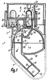
- Fig. 1
- ein erfindungsgemäßer Spender im Axialschnitt,
- Fig. 2
- der Spender gemäß Fig. 1 in teilweise geschnittener Ansicht von unten und
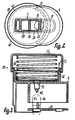
- Fig. 3
- einen Ausschnitt einer weiteren Ausführungsform mit Druckerzeuger für einen Förderstrom.
- Fig. 1
- an inventive donor in axial section,
- Fig. 2
- 1 in a partially sectioned view from below and
- Fig. 3
- a section of a further embodiment with pressure generator for a flow.
Der Spender 1 weist einen Grundkörper 2 aus nur fünf Gehäuseteilen
3 bis 7 auf. Von diesen bilden im Bereitschafts- bzw.
Betriebszustand lediglich drei festsitzend verbundene Teile
3, 4, 6 gemeinsam mit einer Magazin-Einheit 8 die gesamte
Außenfläche der Austrag-Vorrichtung 1. Der Teil 5 ist vollständig
versenkt festsitzend im Teil 3 angeordnet und durch
den Teil 4 unmittelbar axial gesichert. Die Einheit 8 weist
mindestens vier und höchsten acht gleichmäßig verteilte und
unmittelbar benachbart zueinander in einem Kranz um eine
Achse 10 angeordnete Speicherplätze 9 für das Medium auf. Die
Achse 10 ist parallel zur Hauptachse 11, in welcher der jeweils
in Betriebstellung stehende Platz 9 liegt. Unmittelbar
aus dieser Stellung heraus wird der Platz 9 für den Austrag
durch einen Auslaß 12 entleert. Dessen Achse 13 liegt unter
einem stumpfen Winkel von mindestens 110° und höchstens
160°, insbesondere 135°, zur Achse 10 bzw. 11. In Ansicht
parallel zur Achse 10, 11 liegt der Auslaß 12 vollständig
innerhalb des Außenumfanges des Grundkörpers 2.The
Vollständig innerhalb des Grundkörpers 2 ist eine dessen
beide Enden verbindende Fluidführung 14 bzw. Kanalisierung
vorgesehen. Zwischen deren Enden liegt ein Speicherauslaß 15,
um das Medium abzugeben. Der Auslaß 15 hat einen wesentlich
kleineren Abstand vom stromaufwärts liegenden Ende der
Führung 14 als von deren Austrittsende 12. Der Auslaß 15 ist
durch ein Ende eines langgestreckten, gesonderten Speicherkörpers
16 mit langgestrecktem Speicherraum 17 gebildet.
Dieser ist in der Entleerungsstellung mit der Achse 11 koaxial.
Der formsteife Körper 16 ist durch eine zweiteilige
Kapsel aus Hartgelatine o. dgl. gebildet. Deren beide hülsenförmige
Teile sind eng aneinander angepaßt axial zusammengesteckt.
Die voneinander abgekehrten Kapselenden sind halbkugelförmig.
Das im Raum 17 enthaltene Medium ist vor Öffnung
mit einer Vorrichtung 18 dicht verschlossen verpackt. Das
nicht gasförmige, fließfähige Medium füllt den Raum 17 vollständig
oder nur teilweise als Einzel-Anwendungsdosis aus.
Der Körper 16 bzw. Raum 17 ist nur durch Zerstörung zu
öffnen. Er bildet im Betrieb einen über seine gesamte Länge
reichenden Abschnitt der Führung 14. Die an den beiden
Raumenden liegenden Öffnungen sind drosselartig wesentlich
enger als zwischen den Enden liegende Teil des Raumes 17.
Dieser Teil hat durchgehend konstante Durchlaßquerschnitte.Completely within the base body 2 is one of them
Der freiliegende, nur durch die Teile 3, 4, 6, 8 gebildete
Außenmantel 19 der Vorrichtung 1 kann mit einer einzigen Hand
nahezu vollständig umschlossen werden. Innerhalb dieses
Mantels 19 bildet die Führung 14 eine Zone 20 zur Verwirbelung,
Zerkleinerung und feinst verteilten Aufbereitung des
Mediums. Das Medium wurde bereits stromaufwärts der Zone 20
vom Luftstrom aufgenommen. Mittig zwischen den Enden der
Führung 14 bzw. der Vorrichtung 1 ist in Betriebsstellung
unterhalb des Auslasses 15 eine schalen- oder rinnenförmige
Vorlage 21 vorgesehen. Sie ist nur nach oben offen. Ihr
Boden 24 hat vom Auslaß 15 einen gegenüber der Länge des
Raumes 17 kleineren Abstand. Der konkav gekrümmte Boden 24
schließt an eine längere Flanke 22 und eine kürzere Flanke 23
an. Die Flanken 22, 23 divergieren nach oben spitzwinklig.
Die zwischen den Achsen 10, 11, jedoch näher bei der Achse 10
liegende gemeinsame Axialebene der Flächen 22 bis 24 bzw. der
Mulde 21 ist seitlich gegenüber der Achse 11 des Auslasses 15
versetzt. Der Auslaß 15 liegt vertikal über der Mitte des
Bodens 24, wenn die Vorrichtung 1 in Betriebstellung geringfügig
nach hinten gekippt ist. Dabei ist die Achse 13 flacher
als bei vertikaler Ausrichtung der Achsen 10, 11 schräg gestellt
ist.The exposed one, formed only by parts 3, 4, 6, 8
Die Flanke 22 schließt abgedichtet an den Auslaß 15 an. Die
Flanke 23 reicht nur bis zu einem verengten Übertritt 25
zwischen der Mulde 21 und dem stromabwärts davon liegenden
Teil der Führung 14. Die Flanke 23 reicht bis zu einer abgerundeten
Kante 26, die über ihre Länge konkav ist. Die Kante
26 liegt einer darüberliegenden, konkaven Fläche 27 gegenüber.
Sie ist wie die Mulde 21 um eine zu den Achsen 10, 11
rechtwinklig querliegende Achse gekrümmt. Sie hat einen
gegenüber dem Boden 24 mindestens vier- oder fünfach größeren
Krümmungsradius. Die Fläche 27 reicht in und entgegen Strömungsrichtung
über den von der Kante 26 begrenzten Übertritt
25 hinaus. Die Fläche 27 reicht bis zum Auslaß 15 und als
Umfangsbegrenzung bis in einen Kanalabschnitt 28. Dieser
schließt stromabwärts an den Übertritt 25 und die Kante 26
an.The flank 22 connects to the outlet 15 in a sealed manner. The
Flank 23 only extends to a
Das stromabwärts liegende Ende des Abschnittes 28 schließt
stumpfwinklig gekrümmt an einen Endkanal 29 an. Dessen Ende
bildet den Auslaß 12. Die Achse 30 des Abschnittes 28 liegt
parallel zur Achse 10, 11 und auf der von der Achse 11 abgekehrten
Seite der Achse 10. Die beiden Kanalabschnitte 28, 29
sind jeweils geradlinig. Sie haben durchgehend konstante
Durchlaßquerschnitte, welche größer als derjenige des Übertrittes
25 sind. Der Abschnitt 29 ist durch einen frei vorstehenden,
rohrförmigen Stutzen 31 konstanter Außenquerschnitte
gebildet. Das Mundstück 31 ist über einen größten
Teil seiner Länge in den Mund des Patienten einzuführen und
mit dessen Lippen dicht zu umschließen. Der Abschnitt 29
kann dabei geringfügig länger als der Abschnitt 28 bis zur
Kante 26 sein. Mulde 21 und Stutzen 31 liegen an derselben
Seite des Abschnittes 28.The downstream end of
Die Mulde 21 einschließlich der Flächen 22 bis 24, 26 und
eines ersten Längsabschnittes des Kanalteiles 28 ist ausschließlich
vom Teil 5 begrenzt. Dieses ist entgegen Strömungsrichtung
in den Teil 3 bis zum Anschlag vollständig
versenkt eingesetzt und durch den in dieser Richtung ebenfalls
eingesetzten Teil 4 axial gesichert. Der Teil 4 bildet
einen innerhalb des Teiles 3 anschließenden Längsabschnitt
des Kanalteiles 28 sowie den Abschnitt 29, den Stutzen 31 und
den Auslaß 12. Der Teil 4 steht über den Außenumfang des
Teiles 3 nicht vor und schlägt an dessen unterer, ringförmiger
Stirnfläche mit einer Ringschulter abgedichtet an. Die
Fläche 27 reicht über einen Bogenwinkel von weniger als 90°
und mehr als 45°. Die Fläche 27 ist nur durch den Teil 3
gebildet sowie an beiden Enden kontinuierlich fortgesetzt.
So bildet sie einen Zwischenabschnitt einer halbkreis- oder
halkugelförmigen bzw. U-förmigen Innenfläche des Teiles 3.
Diese Innenfläche weist an eine Fortsetzung auf, welche an
die Fläche 27 anschließendt. Der Teil 5 liegt mit konvexen
Flächen an dieser Fortsetzung dicht an. Im Anschluß an den
Teil 5 liegt der Teil 4 mit einer Umfangsfläche dicht an der
Fortsetzung an.The trough 21 including the surfaces 22 to 24, 26 and
a first longitudinal section of the
Die Flanke 22 reicht bis zu diesen gekrümmten Flächen. Die
Fläche 27 ist im Bereich des Auslasses 15 sowie im Anschluß
an die Flanke 22 von einer Übertrittsöffnung 46 für das
Medium und den Lufstrom durchsetzt. Die Öffnung 46 liegt in
der Achse 11. Der Durchlaßquerschnitt der Öffnung 46 entspricht
dem größten Durchlaßquerschnitt des Raumes 17. Die
Weite der Übertrittsöffnung 46 ist größer als die größte
Weite des Raumes 17. Die Mulde 21 liegt zwischen den Achsen
11, 30. Die größte Weite der Mulde 21 ist in Höhe der Kante
26 größer als die zugehörige Tiefe dieser Mulde 21. Die
Kanalabschnitte 21, 25, 28 weisen parallel zur Zeichenebene
liegende Begrenzungen auf. Sie können annähernd eben sowie
zueinander parallel sein. Dann ist die Vorrichtung im zugehörigen
Bereich in Axialansicht stegförmig. Dieser Bereich
kann wie die genannten Flächen, aber auch rotationsförmig um
die Achse 11 gekrümmt sein.The flank 22 extends up to these curved surfaces. The
Surface 27 is in the area of the outlet 15 and in the connection
to the flank 22 of a
Mit Abstand oberhalb der Anordnungen 12, 29, 31 bildet der
Teil 4 des Körpers 2 eine ballig gekrümmte Handhabe 32. Sie
schließt im einspringenden, spitzen Winkel rechtwinklig quer
zur Achse 11 an das hintere Ende des Außenumfanges des Mundstückes
31 an. Zum davon entfernten Bereich steigt die Fläche
32 bis zum Außenumfang des Mantels 19 an. Die andere Handhabe
33 ist durch das hintere Ende des Körpers 2 gebildet, nämlich
durch die Außenseite der Stirnwand des Teiles 6. Die beiden
Handhaben bilden einen Handgriff 32, 33. Der Daumen kann an
der Handhabe 32 anliegen und weitere Finger derselben Hand
können klammerartig an der davon abgekehrten Handhabe 33 anliegen.
Gleichzeitig ist das Mundstück 31 zwischen den Lippen
des Patienten eingeführt. Dabei kann sich der Finger, welcher
an der konvexen Handhabe 32 abgestützt ist, auch an der Oberlippe
des Patienten sowie mit seiner davon abgekehrten Seite
am Außenumfang des Mundstückes 31 anlegen. Die Handhaben 32,
33 liegen während des gesamten Betriebes und Austrages lagestarr
zueinander.At a distance above the
Die Einheit 8 weist einen um die Achse 10 bewegbaren Magazinkörper
34 auf. Dieser ist axial zwischen den Teilen 3,6 festgelegt.
Er trägt an seiner dem Teil 6 zugekehrten Seite auswechselbar
einen Magazineinsatz 35 mit der genannten Anzahl
der Speicherkörper 16. Der Körper 34 weist für jeden Platz 9
eine Halterung 36 auf, die in Strömungsrichtung frei vorsteht
und hülsenförmig ist. Die Halterung 36 umschließt abgedichtet
sowie eng nur das eine untere Ende des Körpers 16. Durch Verengung
bildet der Mantel 36 einen Anschlag für die untere,
gekrümmte Endfläche des Körpers 16. Eine entsprechende Halterung
37 steht nur in Strömungsrichtung vor. Sie ist wesentlich
kürzer als die Halterung 36. Für jeden Platz 9 ist am
Einsatz 35 ein Mantel 37 vorgesehen. Sie steht nur über die
untere Stirnseite des Einsatzes 35 vor, der ansonsten kreis- bzw.
scheibenförmig eben ist. Die Manschette 37, greift mit
einem konischen Außenumfang in eine konische Innenfläche am
hinteren Ende der Halterung 36 ein. So liegt sie radial
verengt dicht am Außenumfang des engeren Teiles des Körpers
16 an. Dessen erweiterter Deckelteil kann mit seiner Stirnfläche
an der oberen Stirnfläche der Einsatzscheibe 35 anliegen.
Dadurch ragt dieses hintere Ende bzw. der Deckelteil
entgegen Strömungsrichtung berührungsfrei in den Innenraum
des Teiles 6. Der untere Längsabschnitt der Kapsel 16 liegt
vollständig in den Halterungen 36, 37 und durchsetzt die
Körper 34, 35. Wie jedes der anderen Teile 3 bis 7, 35 ist
der Körper 34 einteilig ausgebildet. Er weist am äußersten
Umfang einen Mantel 38 auf. An dessen Innenumfang schließt
mit Abstand zwischen seinen Enden eine Stirnwand 39 an. Über
deren Unterseite stehen die Halterungen 36 vor. An der oberen
Stirnfläche liegt der Einsatz 35 an. Der Außenumfang des
Mantels 38 bildet eine Handhabe 40. sie reicht um die Achse
10 über einen Bogenwinkel von mindestens 90° oder 160° und
höchstens 220°, insbesondere nur 180°. Sie ist am Außenumfang
der Körper 3, 6 nur über diesen Winkel zur Betätigung frei
zugänglich. In der Betriebsstellung liegt das verengte Ende
bzw. der Auslaß 15 der Halterung 36 unmittelbar benachbart
zur Übertrittsöffnung 46 in der Fläche 27 bzw. zur Außenseite
der gekrümmten Wandung 47, welche die Fläche 27 bildet.The unit 8 has a magazine body which can be moved about the axis 10
34 on. This is fixed axially between the parts 3.6.
It carries replaceable on its side facing part 6
a
Der Körper 34 liegt vollständig an dieser Außenseite. Er ist
unmittelbar am Teil 3 mit zwei konzentrischen Lagern 41, 42
drehbar gelagert sowie in entgegengesetzter Richtung axial
gesichert. Die Lagerteile sind einteilig mit dem Teil 3 ausgebildet.
Sie sind durch zwei ineinander liegende Lagerkörper
gebildet beispielsweise Hülsen, die entgegen der Strömungsrichtung
frei ausragen. Mit ihren Endflächen gleiten die
Hülsen an der Unterseite der Wand 39. Die äußere Hülse des
äußeren Lagers 41 gleitet mit ihrem Außenumfang am Innenumfang
des Mantels 38 und mit ihrem Innenumfang an den Außenumfängen
der Halterungen 36. Die innere Hülse des inneren
Lagers 42 gleitet mit ihrem Außenumfang ebenfalls an den
Außenumfängen der Halterungen 36, die hierfür gemeinsam einen
Innenumfang bilden. Zwischen den beiden Hülsen liegt die Öffnung
46, die an den Auslaß 15 anschließt. Die beiden Hülsen
gehen einteilig in die gekrümmte Wandung der Fläche 27 über.
Die Hülse des Lagers 41 ist exzentrisch zur Achse 11 des
darunter anschließenden Gehäuseteiles 3, 4 des Körpers 2
vorgesehen und steht auf der von der Handhabe 32 abgekehrten
Seite über die Teile 3, 4 vor. Zur Axialsicherung kann an
einer der Hülsen, insbesondere zwischen dem Außenumfang der
inneren Hülse und dem Körper 34, eine Schnappverbindung vorgesehen
sein. Nach vollständigem Abnehmen des Teiles 6 ist
der Einsatz 35 einschließlich der entleerten Körper 16 entgegen
Strömungsrichtung herauszuziehen. Dabei muß der Körper
34 nicht aus der Lagerung 41, 42 gelöst werden.The
Ein weiteres Radial- und Axiallager ist an der oberen Seite
der Körper 35, 39 vorgesehen. Dafür gleitet der Mantel 43 des
Teiles 6 auf dieser Seite am Innenumfang des Mantels 38 und
an der oberen Stirnfläche des Körpers 35. Der Körper 35 wird
in engem Kontakt mit der Oberseite der Wandung 39 gehalten.
Der Mantel 43 bildet nur über einen Teilumfang auch den
Außenmantel des Teiles 6, da er exzentrisch zu diesem Außenmantel
liegt. Außerhalb des Lagergliedes 43 greift dieser
Außenmantel in das Innere des Mantels des Teiles 3 festsitzend
ein. Dabei ist der Außenmantel durch eine federnde
Schnappsicherung gegen Abziehen gesichert. Durch Anwendung
einer entsprechend hohen Abzugkraft kann er dennoch entgegen
Strömungsrichtung abgelöst werden. Nach diesem Ablösen liegt
der Körper 35 mit den Körpern 16 frei zugänglich zum Auswechseln.Another radial and axial bearing is on the upper side
the
Die Vorrichtung 18 weist zwei in der Achse 11 und einander
gegenüberliegende Öffnungsglieder 44, 45 auf. Sie sind durch
Metallspitzen gebildet und dienen zum Aufbrechen der Endwandungen
der Kapsel 16 während der Schaltbewegung der Einheit
8. Die Kapsel 16 wird dadurch in der letzten Phase der Überführung
in die Betriebsstellung von den Gliedern 44, 45 erfaßt
und an den Enden zersplittert. Dann ragen die spitzen in
den Raum 17 hinein, wobei jede von einer gezackten Öffnung
umgeben ist. Die zugehörige Übertrittsöffnung 46 der gekrümmten
Wand 47 wird vom Glied 44 durchsetzt. Es ist an der Wand
47 mit den Armen einer sternförmigen Halterung lagegesichert.
Der Außenumfang der Spitze 44 bildet eine Leitfläche. Durch
sie werden das Medium und der Luftstrom in einen Hüllstrom
aufgeweitet. Die hintere Spitze 45 ist an der Innenseite der
Stirnwand des Teiles 3 befestigt. Die Spitzen 44, 45 sind
koaxial gegeneinander gerichtet. Der Ring 38, ist mit einer
Anzeigeeinrichtung für seine Drehstellung versehen und rastet
in jeder Betriebstellung federnd ein.The
Zum Gebrauch des Spenders 1 wird der Ring 38 soweit gedreht,
bis die nächste Kapsel 16 in der Achse 11 liegt und dann an
beiden Enden geöffnet ist. Durch das Öffnen rieselt ein Teil
des Mediums entlang der Spitze 44, dann über eine freie Fallstrecke
und dann entlang der Flanke 22 bzw. 23 auf den Boden
24 der Mulde 21. Danach saugt der Patient am Mundstück 31.
Dabei wird durch Öffnungen in dem Gehäuseraum, welcher das
obere Ende der Kapsel 16 und die Spitze 45 aufnimmt, von
außen Luft angesaugt. Sie strömt durch die obere Öffnung der
Kapsel 16 in den Raum 17.To use the
Die Luft durchströmt den Raum 17 unter Mitnahme des Restes
des Mediums, das noch in diesem Raum 17 ist. Das Mischmedium
strömt dann durch den Auslaß 15 um die Spitze 44 herum unmittelbar
in die Öffnung 46. Von dieser strömt es gegen die
näher beim Auslaß 12 liegende Flanke 22. Der Förderstrom wird
entlang der Flanke 22 und des Bodens 24 zurück nach oben umgelenkt,
reißt an der Kante 26 ab und wird unmittelbar gegen
die Fläche 27 geleitet. Hierbei nimmt der Förderstrom das in
der Mulde 21 befindliche Medium mit. Im Bereich der Mulde 21
kann dabei kurz eine Walzenströmung entstehen. Durch die
Saugwirkung wird die Strömung beschleunigt. Der Förderstrom
fließt durch den Übertritt 25 in den Kanal 28, 29. Dort
erfolgt eine Strömungsberuhigung, die sich bis zum Auslaß 12
fortsetzt. Beim Auftreffen auf der Fläche 27, gegenüber
welcher die Flanke 23 auf einem Radiusstrahl liegt, werden
größere Medienpartikel durch Prallwirkung zerkleinert. Für
die nächste Anwendung wird die Einheit 8 um einen Platz 9
weitergedreht. Die Einheit 8 ist mit einem Freilaufgesperre
nur in einer einzigen Richtung drehbar.The air flows through the room 17, taking the rest with it
of the medium that is still 17 in this room. The mixed medium
then flows directly through the outlet 15 around the
Stromabwärts vom Auslaß 15 bzw. vom Übertritt 25 ist zweckmäßig
im Kanal 28 ein Sieb 48 oder ein Filter vorgesehen. Es
ist zwischen den Teilen 3, 4 eingesetzt. Dadurch können eventuell
abgesplitterte Teilchen der Kapsel 16 oder zu große
Medienpartikel nicht in den Rachenraum des Patienten gelangen.
Ferner kann im Strömungsweg, nämlich stromaufwärts oder
stromabwärts vom Raum 17, ein Ventil 49 vorgesehen sein. Es
öffnet druckabhängig dann, wenn stromabwärts ein geringerer
Druck als stromaufwärts anliegt. Das Ventil kann mit zunehmender
Öffnung eine konstante oder abnehmende Öffnungskraft
aufweisen. Dann öffnet es nach Beginn der Öffnung schlagartig
vollständig und der Förderstrom wird impulsartig freigegeben.
Das Ventil 49 kehrt druckabhängig zur Schließstellung zurück.
Das Ventil 49 liegt nahe zum Auslaß 12 innerhalb des Kanales
29. Dadurch ist der stromaufwärts liegende Abschnitt der
Führung 14 während der Ruhezeiten gegen Eindringen von Verunreinigungen
dicht geschlossen. Der Teil 7 ist als Schutzkappe
ausgebildet. Sie wird für den Gebrauch axial vollständig
abgezogen. Der Teil 7 nimmt in Schutzlage den Stutzen 31
einschließlich Öffnung 12 sowie das gesamte Teil 4 und den
unteren Abschnitt des Teiles 3 dicht verschlossen auf.Downstream from the outlet 15 or from the
In Fig. 3 ist nur der obere Abschnitt des Spenders ab dem
Teil 6 dargestellt. An dessen Oberseite ist als Druckerzeuger
eine Luftpumpe 50 angeordnet. Die obere Stirnwand des Teiles
6 bildet hier nicht eine Handhabe, sondern weist einen nach
oben frei vorstehenden Mantel 52 auf. In diesen ist ein napfförmiger
Kolben 41 mit seinem Mantel bis zum Anschlag an der
Stirnwand des Teiles 6 fest eingesetzt. Die erweiterte
Kolbenlippe steht über das obere Ende des Mantels 52 vor. Die
Kolbenlippe gleitet an einem Zylinder 53. Dieser umgibt den
Außenumfang des Mantels 52 eng. Der Zylinder 53 kann bis zum
Anschlag an der Stirnwand des Teiles 6 gegen die Kraft einer
Feder 54 nach unten verschoben werden. Dadurch wird Luft
durch eine Öffnung 55 im Kolbenboden sowie in der Stirnwand
des Teiles 6 um die Spitze 45 herum der Kapsel 16 zugeführt.
Die Pumpe 50 liegt in der Achse 11. Die Stirnwand des Zylinders
53 bildet die bewegliche Handhabe 33. Nach deren Freigabe
kehrt die Pumpe unter Ansaugen von Frischluft in ihre Ausgangslage
zurück. Dabei kann der Weg durch die Öffnung 55 mit
einem Ventil, beispielsweise dem Ventil 49, gegen Ansaugen
geschlossen sein. Auch hier kann der Luftstrom allein durch
Ansaugen durch die Öffnung 12 erzeugt und zu jeder beliebigen
Zeit durch Betätigen der Pumpe 50 verstärkt werden. In Fig. 3
ist der Einsatz 35 in seiner Wechselstellung für sich und
ohne Einsatz 34 dargestellt.In Fig. 3 is only the upper portion of the dispenser from
Part 6 shown. At the top is as a pressure generator
an
Alle angegebenen Wirkungen und Eigenschaften, wie Lagen,
Größen usw., können genau wie beschrieben oder nur etwa bzw.
im wesentlichen wie beschrieben vorgesehen sein und je nach
Anwendungszweck auch stark davon abweichen. Der Spender kann
maßstäblich gemäß den Figuren 1 bis 3 ausgebildet sein. Die
Begrenzungsflächen der Bereiche, die mit dem Medium in Berührung
kommen, insbesondere der Bereiche 12, 14, 18, 20 bis 29,
44 bis 46, 48 und 49, können mit einer antihaft- bzw. antistatischen
Beschichtung aus Metall und/oder Kunststoff, wie
Tetrafluoräthylen, versehen sein. Dadurch kann ein Anhaften
des Mediums durch elektrische Aufladung od.dgl. vermieden
werden. Die Beschichtung ist nur wenige µm dünn sein. Sie
kann durch Lackieren, Kleben, Drucken od.dgl. auf die Flächen
der genannten Bereiche aufgetragen sein.All specified effects and properties, such as layers,
Sizes etc., can be exactly as described or only approximately or
be provided essentially as described and depending on
Application also deviate significantly from it. The donor can
be designed to scale according to Figures 1 to 3. The
Boundary areas of the areas in contact with the medium
come, especially in
Claims (11)
Applications Claiming Priority (2)
| Application Number | Priority Date | Filing Date | Title |
|---|---|---|---|
| DE19647947A DE19647947A1 (en) | 1996-11-20 | 1996-11-20 | Discharge device for media |
| DE19647947 | 1996-11-20 |
Publications (2)
| Publication Number | Publication Date |
|---|---|
| EP0844007A2 true EP0844007A2 (en) | 1998-05-27 |
| EP0844007A3 EP0844007A3 (en) | 1998-12-09 |
Family
ID=7812191
Family Applications (1)
| Application Number | Title | Priority Date | Filing Date |
|---|---|---|---|
| EP97118019A Withdrawn EP0844007A3 (en) | 1996-11-20 | 1997-10-17 | Product dispenser |
Country Status (4)
| Country | Link |
|---|---|
| US (1) | US5964417A (en) |
| EP (1) | EP0844007A3 (en) |
| JP (1) | JPH10155907A (en) |
| DE (1) | DE19647947A1 (en) |
Cited By (30)
| Publication number | Priority date | Publication date | Assignee | Title |
|---|---|---|---|---|
| EP0950423A2 (en) | 1998-04-18 | 1999-10-20 | Ing. Erich Pfeiffer GmbH | Product dispenser, especially for powder |
| EP1466642A3 (en) * | 1998-08-26 | 2005-11-30 | Bespak Plc | Drug delivery devices |
| EP1649886A2 (en) * | 1999-07-23 | 2006-04-26 | Mannkind Corporation | Unit dose capsules for a dry powder inhaler |
| EP1726323A2 (en) * | 1999-12-17 | 2006-11-29 | Nektar Therapeutics | Receptacles to facilitate the extraction of powders |
| US7464706B2 (en) | 1999-07-23 | 2008-12-16 | Mannkind Corporation | Unit dose cartridge and dry powder inhaler |
| US8146588B2 (en) | 1999-07-23 | 2012-04-03 | Mannkind Corporation | Unit dose capsules and dry powder inhaler |
| US9610351B2 (en) | 2011-10-24 | 2017-04-04 | Mannkind Corporation | Methods and compositions for treating pain |
| US9630930B2 (en) | 2009-06-12 | 2017-04-25 | Mannkind Corporation | Diketopiperazine microparticles with defined specific surface areas |
| US9700690B2 (en) | 2002-03-20 | 2017-07-11 | Mannkind Corporation | Inhalation apparatus |
| US9706944B2 (en) | 2009-11-03 | 2017-07-18 | Mannkind Corporation | Apparatus and method for simulating inhalation efforts |
| US9717689B2 (en) | 2005-09-14 | 2017-08-01 | Mannkind Corporation | Method of drug formulation based on increasing the affinity of crystalline microparticle surfaces for active agents |
| US9796688B2 (en) | 2004-08-20 | 2017-10-24 | Mannkind Corporation | Catalysis of diketopiperazine synthesis |
| US9801925B2 (en) | 1999-06-29 | 2017-10-31 | Mannkind Corporation | Potentiation of glucose elimination |
| US9802012B2 (en) | 2012-07-12 | 2017-10-31 | Mannkind Corporation | Dry powder drug delivery system and methods |
| US9925144B2 (en) | 2013-07-18 | 2018-03-27 | Mannkind Corporation | Heat-stable dry powder pharmaceutical compositions and methods |
| US9943571B2 (en) | 2008-08-11 | 2018-04-17 | Mannkind Corporation | Use of ultrarapid acting insulin |
| US9983108B2 (en) | 2009-03-11 | 2018-05-29 | Mannkind Corporation | Apparatus, system and method for measuring resistance of an inhaler |
| US10130709B2 (en) | 2011-06-17 | 2018-11-20 | Mannkind Corporation | High capacity diketopiperazine microparticles and methods |
| US10130685B2 (en) | 2004-08-23 | 2018-11-20 | Mannkind Corporation | Diketopiperazine salts for drug delivery and related methods |
| US10130581B2 (en) | 2006-02-22 | 2018-11-20 | Mannkind Corporation | Method for improving the pharmaceutic properties of microparticles comprising diketopiperazine and an active agent |
| US10159644B2 (en) | 2012-10-26 | 2018-12-25 | Mannkind Corporation | Inhalable vaccine compositions and methods |
| US10172850B2 (en) | 2008-12-29 | 2019-01-08 | Mannkind Corporation | Substituted diketopiperazine analogs for use as drug delivery agents |
| US10201672B2 (en) | 2008-06-13 | 2019-02-12 | Mannkind Corporation | Dry powder inhaler and system for drug delivery |
| US10307464B2 (en) | 2014-03-28 | 2019-06-04 | Mannkind Corporation | Use of ultrarapid acting insulin |
| US10342938B2 (en) | 2008-06-13 | 2019-07-09 | Mannkind Corporation | Dry powder drug delivery system |
| US10421729B2 (en) | 2013-03-15 | 2019-09-24 | Mannkind Corporation | Microcrystalline diketopiperazine compositions and methods |
| US10561806B2 (en) | 2014-10-02 | 2020-02-18 | Mannkind Corporation | Mouthpiece cover for an inhaler |
| US10625034B2 (en) | 2011-04-01 | 2020-04-21 | Mannkind Corporation | Blister package for pharmaceutical cartridges |
| US10675421B2 (en) | 2008-06-20 | 2020-06-09 | Mannkind Corporation | Interactive apparatus and method for real-time profiling of inhalation efforts |
| US11446127B2 (en) | 2013-08-05 | 2022-09-20 | Mannkind Corporation | Insufflation apparatus and methods |
Families Citing this family (39)
| Publication number | Priority date | Publication date | Assignee | Title |
|---|---|---|---|---|
| US5758637A (en) | 1995-08-31 | 1998-06-02 | Aerogen, Inc. | Liquid dispensing apparatus and methods |
| DK0865302T3 (en) | 1995-12-07 | 2000-10-02 | Jago Pharma Ag | Inhalator for repeated dose delivery of pharmacological dry powder |
| US7131441B1 (en) | 1995-12-07 | 2006-11-07 | Skyepharma Ag | Inhaler for multiple dosed administration of a pharmacological dry powder |
| DE19831525A1 (en) * | 1998-07-14 | 2000-01-20 | Pfeiffer Erich Gmbh & Co Kg | Media Donor |
| DE19942791A1 (en) * | 1999-09-08 | 2001-03-15 | Pfeiffer Erich Gmbh & Co Kg | Media Donor |
| US6235177B1 (en) | 1999-09-09 | 2001-05-22 | Aerogen, Inc. | Method for the construction of an aperture plate for dispensing liquid droplets |
| DE19961300A1 (en) | 1999-12-18 | 2001-06-21 | Asta Medica Ag | Storage system for medicinal products in powder form and inhaler equipped with them |
| DE10011120A1 (en) * | 2000-03-09 | 2001-09-13 | Pfeiffer Erich Gmbh & Co Kg | Media Donor |
| US7971588B2 (en) | 2000-05-05 | 2011-07-05 | Novartis Ag | Methods and systems for operating an aerosol generator |
| US7100600B2 (en) * | 2001-03-20 | 2006-09-05 | Aerogen, Inc. | Fluid filled ampoules and methods for their use in aerosolizers |
| US8336545B2 (en) | 2000-05-05 | 2012-12-25 | Novartis Pharma Ag | Methods and systems for operating an aerosol generator |
| WO2003057291A1 (en) | 2002-01-07 | 2003-07-17 | Aerogen, Inc. | Devices and methods for nebulizing fluids for inhalation |
| US7677467B2 (en) | 2002-01-07 | 2010-03-16 | Novartis Pharma Ag | Methods and devices for aerosolizing medicament |
| WO2003059424A1 (en) | 2002-01-15 | 2003-07-24 | Aerogen, Inc. | Methods and systems for operating an aerosol generator |
| US7258118B2 (en) | 2002-01-24 | 2007-08-21 | Sofotec Gmbh & Co, Kg | Pharmaceutical powder cartridge, and inhaler equipped with same |
| US6915962B2 (en) | 2002-05-20 | 2005-07-12 | Aerogen, Inc. | Apparatus for providing aerosol for medical treatment and methods |
| DE10245326A1 (en) * | 2002-09-27 | 2004-04-08 | Abb Patent Gmbh | A method for atomizing paint coating materials has an ultrasonic generator and reflector setting up standing waves maximized at the center |
| DE10252437A1 (en) * | 2002-11-12 | 2004-05-27 | Abb Patent Gmbh | Ultrasonic standing wave atomizer appliance for coating components e.g. in the motor vehicle industry has paint feeder with paint discharge pipe sections in area of selected maximum of sound particle velocity of vertical ultrasonic field |
| US8616195B2 (en) | 2003-07-18 | 2013-12-31 | Novartis Ag | Nebuliser for the production of aerosolized medication |
| DE10352277A1 (en) * | 2003-11-08 | 2005-06-02 | Boehringer Ingelheim Pharma Gmbh & Co. Kg | powder inhaler |
| EP1711220A1 (en) * | 2004-01-16 | 2006-10-18 | Biodel, Inc. | Sublingual drug delivery device |
| US7946291B2 (en) | 2004-04-20 | 2011-05-24 | Novartis Ag | Ventilation systems and methods employing aerosol generators |
| CA2563365A1 (en) * | 2004-04-23 | 2005-11-03 | Mystic Pharmaceuticals, Inc. | Multiple unit dose drug delivery system |
| GB0420513D0 (en) * | 2004-09-15 | 2004-10-20 | Optinose As | Powder delivery devices |
| AU2014253488A1 (en) * | 2004-09-15 | 2014-11-13 | Optinose As | Nasal delivery devices |
| PL370286A1 (en) * | 2004-09-23 | 2006-04-03 | Glaxosmithkline Pharmaceuticals Spółka Akcyjna | Powder inhaler - capsules opening and emptying system |
| EA012656B1 (en) | 2005-05-25 | 2009-12-30 | Аэроджен, Инк. | Vibration systems and use thereof |
| US20070212307A1 (en) * | 2006-02-10 | 2007-09-13 | Daniel Wermeling | Pharmaceutical Compositions Comprising an Opioid Receptor Antagonist and Methods of Using Same |
| GB0611659D0 (en) * | 2006-06-13 | 2006-07-19 | Cambridge Consultants | Dry powder inhalers |
| JP2010515541A (en) | 2007-01-09 | 2010-05-13 | ミスティック ファーマシューティカルズ, インコーポレイテッド | Nasal cartridge device |
| CA2688689C (en) | 2007-05-16 | 2015-06-30 | Mystic Pharmaceuticals, Inc. | Combination unit dose dispensing containers |
| US8683995B2 (en) | 2007-05-16 | 2014-04-01 | Mystic Pharmaceuticals, Inc. | Dose dispensing containers |
| US9248076B2 (en) | 2007-05-16 | 2016-02-02 | Mystic Pharmaceuticals, Inc. | Dose dispensing containers |
| CN103707452B (en) * | 2007-09-14 | 2017-05-03 | 神秘制药公司 | Deep draw container forming method |
| US8056343B2 (en) * | 2008-10-01 | 2011-11-15 | General Electric Company | Off center combustor liner |
| IT1395945B1 (en) * | 2009-09-30 | 2012-11-02 | Oliva | INHALER PERFECTED FOR POWDER PREPARATIONS |
| RU2571331C1 (en) | 2010-06-21 | 2015-12-20 | Маннкайнд Корпорейшн | Systems and methods for dry powder drug delivery |
| GB2544477A (en) * | 2015-11-16 | 2017-05-24 | 3M Innovative Properties Co | Improvements in or relating to medical actuators |
| US10933208B2 (en) * | 2016-11-14 | 2021-03-02 | Vandana M. Krishna | Asthma inhaler accessory |
Citations (8)
| Publication number | Priority date | Publication date | Assignee | Title |
|---|---|---|---|---|
| GB1118341A (en) * | 1965-04-20 | 1968-07-03 | Fisons Pharmaceuticals Ltd | Inhalation device |
| FR2352556A1 (en) * | 1976-05-26 | 1977-12-23 | Pasteur Institut | Nasal and oral powder inhaler for medicines etc. - uses cyclone chamber to entrain powder into air stream |
| GB2169265A (en) * | 1982-10-08 | 1986-07-09 | Glaxo Group Ltd | Pack for medicament |
| US5113855A (en) * | 1990-02-14 | 1992-05-19 | Newhouse Michael T | Powder inhaler |
| US5239993A (en) * | 1992-08-26 | 1993-08-31 | Glaxo Inc. | Dosage inhalator providing optimized compound inhalation trajectory |
| US5320714A (en) * | 1990-02-16 | 1994-06-14 | Byk Gulden Lomberg Chemische Fabrik Gmbh | Powder inhalator |
| US5366122A (en) * | 1991-08-27 | 1994-11-22 | Ing. Erich Pfeiffer Gmbh & Co. Kg | Dispenser for flowable media |
| US5522383A (en) * | 1990-06-14 | 1996-06-04 | Rhone-Poulenc Rorer Ltd. | Powder inhaler having capsule holding structure and anti-static walls |
Family Cites Families (15)
| Publication number | Priority date | Publication date | Assignee | Title |
|---|---|---|---|---|
| US3888252A (en) * | 1974-01-23 | 1975-06-10 | Anthony J Side | Powder inhaler |
| US4778054A (en) * | 1982-10-08 | 1988-10-18 | Glaxo Group Limited | Pack for administering medicaments to patients |
| DE3811309C2 (en) * | 1988-04-02 | 1997-09-04 | Weitmann & Konrad Fa | Powder atomizing device |
| DE4021263C2 (en) * | 1990-07-04 | 1996-04-11 | Pfeiffer Erich Gmbh & Co Kg | Discharge device for media |
| GB9015522D0 (en) * | 1990-07-13 | 1990-08-29 | Braithwaite Philip W | Inhaler |
| FR2667509B1 (en) * | 1990-10-04 | 1995-08-25 | Valois | POWDER INHALER, DEVICE FOR PACKAGING POWDER MICRODOSES IN THE FORM OF BANDS SUITABLE FOR USE IN A POWDER INHALER, AND METHOD FOR MANUFACTURING SUCH BANDS. |
| GB9027234D0 (en) * | 1990-12-15 | 1991-02-06 | Harris Pharma Ltd | An inhalation device |
| DE4133281A1 (en) * | 1991-10-08 | 1993-04-15 | Kloeckner Humboldt Deutz Ag | Appliance to spray anti-bonding agent to die plate - has collection vessel for agent, moving below die plate, with upward directed spray nozzles |
| DE4134665A1 (en) * | 1991-10-19 | 1993-04-22 | Solvay Deutschland | MEDICAL INHALATION SYSTEM |
| DE4208880A1 (en) * | 1992-03-19 | 1993-09-23 | Boehringer Ingelheim Kg | SEPARATOR FOR POWDER INHALATORS |
| DE4306458C2 (en) * | 1993-03-02 | 1996-06-05 | Lindopharm Gmbh | Nebulizers for medical purposes |
| SE9302550D0 (en) * | 1993-07-30 | 1993-07-30 | Ernst Hoerlin | POWDER INHALES |
| NL9400346A (en) * | 1994-03-07 | 1995-10-02 | Itsac Nv | Liquid dispenser with refill pack. |
| DE4415462C1 (en) * | 1994-05-03 | 1995-08-31 | Transcoject Marketing Gmbh | Inhaler for powdered medicine etc. |
| GB2300371B (en) * | 1995-05-05 | 1997-08-06 | Andrew Ian Briggs | Particulate dispenser |
-
1996
- 1996-11-20 DE DE19647947A patent/DE19647947A1/en not_active Withdrawn
-
1997
- 1997-10-17 EP EP97118019A patent/EP0844007A3/en not_active Withdrawn
- 1997-11-07 US US08/966,377 patent/US5964417A/en not_active Expired - Fee Related
- 1997-11-07 JP JP9320618A patent/JPH10155907A/en active Pending
Patent Citations (8)
| Publication number | Priority date | Publication date | Assignee | Title |
|---|---|---|---|---|
| GB1118341A (en) * | 1965-04-20 | 1968-07-03 | Fisons Pharmaceuticals Ltd | Inhalation device |
| FR2352556A1 (en) * | 1976-05-26 | 1977-12-23 | Pasteur Institut | Nasal and oral powder inhaler for medicines etc. - uses cyclone chamber to entrain powder into air stream |
| GB2169265A (en) * | 1982-10-08 | 1986-07-09 | Glaxo Group Ltd | Pack for medicament |
| US5113855A (en) * | 1990-02-14 | 1992-05-19 | Newhouse Michael T | Powder inhaler |
| US5320714A (en) * | 1990-02-16 | 1994-06-14 | Byk Gulden Lomberg Chemische Fabrik Gmbh | Powder inhalator |
| US5522383A (en) * | 1990-06-14 | 1996-06-04 | Rhone-Poulenc Rorer Ltd. | Powder inhaler having capsule holding structure and anti-static walls |
| US5366122A (en) * | 1991-08-27 | 1994-11-22 | Ing. Erich Pfeiffer Gmbh & Co. Kg | Dispenser for flowable media |
| US5239993A (en) * | 1992-08-26 | 1993-08-31 | Glaxo Inc. | Dosage inhalator providing optimized compound inhalation trajectory |
Cited By (38)
| Publication number | Priority date | Publication date | Assignee | Title |
|---|---|---|---|---|
| EP0950423A2 (en) | 1998-04-18 | 1999-10-20 | Ing. Erich Pfeiffer GmbH | Product dispenser, especially for powder |
| EP1466642A3 (en) * | 1998-08-26 | 2005-11-30 | Bespak Plc | Drug delivery devices |
| US9801925B2 (en) | 1999-06-29 | 2017-10-31 | Mannkind Corporation | Potentiation of glucose elimination |
| US9061111B2 (en) | 1999-07-23 | 2015-06-23 | Mannkind Corporation | Unit dose capsules and dry powder inhaler |
| EP1649886A2 (en) * | 1999-07-23 | 2006-04-26 | Mannkind Corporation | Unit dose capsules for a dry powder inhaler |
| EP1649886A3 (en) * | 1999-07-23 | 2006-07-19 | Mannkind Corporation | Unit dose capsules for a dry powder inhaler |
| US7464706B2 (en) | 1999-07-23 | 2008-12-16 | Mannkind Corporation | Unit dose cartridge and dry powder inhaler |
| US8146588B2 (en) | 1999-07-23 | 2012-04-03 | Mannkind Corporation | Unit dose capsules and dry powder inhaler |
| US8156936B2 (en) | 1999-07-23 | 2012-04-17 | Mannkind Corporation | Unit dose capsules and dry powder inhaler |
| US8215300B2 (en) | 1999-07-23 | 2012-07-10 | Mannkind Corporation | Unit dose cartridge and dry powder inhaler |
| EP1726323A3 (en) * | 1999-12-17 | 2007-08-22 | Nektar Therapeutics | Receptacles to facilitate the extraction of powders |
| EP1726323A2 (en) * | 1999-12-17 | 2006-11-29 | Nektar Therapeutics | Receptacles to facilitate the extraction of powders |
| US9700690B2 (en) | 2002-03-20 | 2017-07-11 | Mannkind Corporation | Inhalation apparatus |
| US9796688B2 (en) | 2004-08-20 | 2017-10-24 | Mannkind Corporation | Catalysis of diketopiperazine synthesis |
| US10130685B2 (en) | 2004-08-23 | 2018-11-20 | Mannkind Corporation | Diketopiperazine salts for drug delivery and related methods |
| US9717689B2 (en) | 2005-09-14 | 2017-08-01 | Mannkind Corporation | Method of drug formulation based on increasing the affinity of crystalline microparticle surfaces for active agents |
| US10143655B2 (en) | 2005-09-14 | 2018-12-04 | Mannkind Corporation | Method of drug formulation |
| US10130581B2 (en) | 2006-02-22 | 2018-11-20 | Mannkind Corporation | Method for improving the pharmaceutic properties of microparticles comprising diketopiperazine and an active agent |
| US10751488B2 (en) | 2008-06-13 | 2020-08-25 | Mannkind Corporation | Dry powder inhaler and system for drug delivery |
| US10342938B2 (en) | 2008-06-13 | 2019-07-09 | Mannkind Corporation | Dry powder drug delivery system |
| US10201672B2 (en) | 2008-06-13 | 2019-02-12 | Mannkind Corporation | Dry powder inhaler and system for drug delivery |
| US10675421B2 (en) | 2008-06-20 | 2020-06-09 | Mannkind Corporation | Interactive apparatus and method for real-time profiling of inhalation efforts |
| US9943571B2 (en) | 2008-08-11 | 2018-04-17 | Mannkind Corporation | Use of ultrarapid acting insulin |
| US10172850B2 (en) | 2008-12-29 | 2019-01-08 | Mannkind Corporation | Substituted diketopiperazine analogs for use as drug delivery agents |
| US9983108B2 (en) | 2009-03-11 | 2018-05-29 | Mannkind Corporation | Apparatus, system and method for measuring resistance of an inhaler |
| US9630930B2 (en) | 2009-06-12 | 2017-04-25 | Mannkind Corporation | Diketopiperazine microparticles with defined specific surface areas |
| US9706944B2 (en) | 2009-11-03 | 2017-07-18 | Mannkind Corporation | Apparatus and method for simulating inhalation efforts |
| US10625034B2 (en) | 2011-04-01 | 2020-04-21 | Mannkind Corporation | Blister package for pharmaceutical cartridges |
| US10130709B2 (en) | 2011-06-17 | 2018-11-20 | Mannkind Corporation | High capacity diketopiperazine microparticles and methods |
| US9610351B2 (en) | 2011-10-24 | 2017-04-04 | Mannkind Corporation | Methods and compositions for treating pain |
| US10258664B2 (en) | 2011-10-24 | 2019-04-16 | Mannkind Corporation | Methods and compositions for treating pain |
| US9802012B2 (en) | 2012-07-12 | 2017-10-31 | Mannkind Corporation | Dry powder drug delivery system and methods |
| US10159644B2 (en) | 2012-10-26 | 2018-12-25 | Mannkind Corporation | Inhalable vaccine compositions and methods |
| US10421729B2 (en) | 2013-03-15 | 2019-09-24 | Mannkind Corporation | Microcrystalline diketopiperazine compositions and methods |
| US9925144B2 (en) | 2013-07-18 | 2018-03-27 | Mannkind Corporation | Heat-stable dry powder pharmaceutical compositions and methods |
| US11446127B2 (en) | 2013-08-05 | 2022-09-20 | Mannkind Corporation | Insufflation apparatus and methods |
| US10307464B2 (en) | 2014-03-28 | 2019-06-04 | Mannkind Corporation | Use of ultrarapid acting insulin |
| US10561806B2 (en) | 2014-10-02 | 2020-02-18 | Mannkind Corporation | Mouthpiece cover for an inhaler |
Also Published As
| Publication number | Publication date |
|---|---|
| JPH10155907A (en) | 1998-06-16 |
| EP0844007A3 (en) | 1998-12-09 |
| DE19647947A1 (en) | 1998-05-28 |
| US5964417A (en) | 1999-10-12 |
Similar Documents
| Publication | Publication Date | Title |
|---|---|---|
| EP0844007A2 (en) | Product dispenser | |
| EP0147755B1 (en) | Inhalator | |
| EP0957962B1 (en) | Medium dispenser | |
| EP1220700B1 (en) | Breathing-controlled inhalation device for dry powder | |
| DE69723156T2 (en) | Regulated flow inhalers | |
| EP0530625B1 (en) | Fluid dispenser | |
| DE69832679T2 (en) | Device for the administration of a drug in aerosol form | |
| DE3429389C1 (en) | Inhaler | |
| DE60032173T2 (en) | CONTAINER FOR SIMPLIFYING THE PROMOTION OF POWDER | |
| DE60027714T3 (en) | DRAINAGE SYSTEM WITH LOW SPRAY POWER AND RETENTION | |
| DE19520622C2 (en) | Device for atomizing fluids | |
| EP0799646B1 (en) | Dosing device for flowing media such as air-powder dispersion | |
| EP0473965B1 (en) | Dispensing device for substances | |
| EP0661070A1 (en) | Inhalation device | |
| EP0972533A2 (en) | Product dispenser | |
| CH646064A5 (en) | INHALATOR FOR ORAL OR NASAL POWDERED MEDICINE. | |
| DE102006023662A1 (en) | inhaler | |
| EP1993644A1 (en) | Inhalator for powdery substances | |
| EP0923993A1 (en) | Fluid dispenser | |
| DE10007591A1 (en) | Medical nebulizer | |
| DE4415462C1 (en) | Inhaler for powdered medicine etc. | |
| DE2600903A1 (en) | INHALATION DEVICE | |
| DE10258360A1 (en) | Chamber for accommodation of disposable capsules for powder inhalers has an inner surface with protruding elements serving as distance pieces between the capsules | |
| DE60013799T2 (en) | powder inhaler | |
| DE19502725A1 (en) | Pump dispenser for a medium |
Legal Events
| Date | Code | Title | Description |
|---|---|---|---|
| PUAI | Public reference made under article 153(3) epc to a published international application that has entered the european phase |
Free format text: ORIGINAL CODE: 0009012 |
|
| AK | Designated contracting states |
Kind code of ref document: A2 Designated state(s): BE CH DE DK ES FI FR GB IT LI NL PT SE |
|
| PUAL | Search report despatched |
Free format text: ORIGINAL CODE: 0009013 |
|
| AK | Designated contracting states |
Kind code of ref document: A3 Designated state(s): AT BE CH DE DK ES FI FR GB GR IE IT LI LU MC NL PT SE |
|
| 17P | Request for examination filed |
Effective date: 19990205 |
|
| AKX | Designation fees paid |
Free format text: BE CH DE DK ES FI FR GB IT LI NL PT SE |
|
| 17Q | First examination report despatched |
Effective date: 20010509 |
|
| STAA | Information on the status of an ep patent application or granted ep patent |
Free format text: STATUS: THE APPLICATION HAS BEEN WITHDRAWN |
|
| 18W | Application withdrawn |
Withdrawal date: 20020305 |