EP0843442A2 - Communication system for communicating a plurality of time-division multiplexed data, and control method therefor - Google Patents
Communication system for communicating a plurality of time-division multiplexed data, and control method therefor Download PDFInfo
- Publication number
- EP0843442A2 EP0843442A2 EP97309129A EP97309129A EP0843442A2 EP 0843442 A2 EP0843442 A2 EP 0843442A2 EP 97309129 A EP97309129 A EP 97309129A EP 97309129 A EP97309129 A EP 97309129A EP 0843442 A2 EP0843442 A2 EP 0843442A2
- Authority
- EP
- European Patent Office
- Prior art keywords
- communication
- data
- reception
- frame
- communication data
- Prior art date
- Legal status (The legal status is an assumption and is not a legal conclusion. Google has not performed a legal analysis and makes no representation as to the accuracy of the status listed.)
- Withdrawn
Links
- 238000004891 communication Methods 0.000 title claims abstract description 312
- 238000000034 method Methods 0.000 title claims description 59
- 230000005540 biological transmission Effects 0.000 claims description 52
- 238000012546 transfer Methods 0.000 description 36
- 238000012545 processing Methods 0.000 description 22
- 238000010586 diagram Methods 0.000 description 13
- 230000006870 function Effects 0.000 description 13
- 230000015654 memory Effects 0.000 description 9
- 230000008859 change Effects 0.000 description 6
- 230000008569 process Effects 0.000 description 6
- 230000004044 response Effects 0.000 description 5
- 230000001755 vocal effect Effects 0.000 description 5
- 230000006835 compression Effects 0.000 description 3
- 238000007906 compression Methods 0.000 description 3
- 230000000694 effects Effects 0.000 description 3
- 238000012360 testing method Methods 0.000 description 3
- 206010002953 Aphonia Diseases 0.000 description 2
- 230000003044 adaptive effect Effects 0.000 description 2
- 230000015572 biosynthetic process Effects 0.000 description 2
- 230000036541 health Effects 0.000 description 2
- 238000012544 monitoring process Methods 0.000 description 2
- 238000006243 chemical reaction Methods 0.000 description 1
- 230000007423 decrease Effects 0.000 description 1
- 230000003111 delayed effect Effects 0.000 description 1
- 238000001514 detection method Methods 0.000 description 1
- 239000000284 extract Substances 0.000 description 1
- 238000009499 grossing Methods 0.000 description 1
- 230000006872 improvement Effects 0.000 description 1
Images


Classifications
-
- H—ELECTRICITY
- H04—ELECTRIC COMMUNICATION TECHNIQUE
- H04Q—SELECTING
- H04Q11/00—Selecting arrangements for multiplex systems
- H04Q11/04—Selecting arrangements for multiplex systems for time-division multiplexing
- H04Q11/0428—Integrated services digital network, i.e. systems for transmission of different types of digitised signals, e.g. speech, data, telecentral, television signals
- H04Q11/0478—Provisions for broadband connections
-
- H—ELECTRICITY
- H04—ELECTRIC COMMUNICATION TECHNIQUE
- H04L—TRANSMISSION OF DIGITAL INFORMATION, e.g. TELEGRAPHIC COMMUNICATION
- H04L12/00—Data switching networks
- H04L12/54—Store-and-forward switching systems
- H04L12/56—Packet switching systems
- H04L12/5601—Transfer mode dependent, e.g. ATM
- H04L2012/5638—Services, e.g. multimedia, GOS, QOS
- H04L2012/5646—Cell characteristics, e.g. loss, delay, jitter, sequence integrity
- H04L2012/5649—Cell delay or jitter
-
- H—ELECTRICITY
- H04—ELECTRIC COMMUNICATION TECHNIQUE
- H04L—TRANSMISSION OF DIGITAL INFORMATION, e.g. TELEGRAPHIC COMMUNICATION
- H04L12/00—Data switching networks
- H04L12/54—Store-and-forward switching systems
- H04L12/56—Packet switching systems
- H04L12/5601—Transfer mode dependent, e.g. ATM
- H04L2012/5638—Services, e.g. multimedia, GOS, QOS
- H04L2012/5646—Cell characteristics, e.g. loss, delay, jitter, sequence integrity
- H04L2012/5652—Cell construction, e.g. including header, packetisation, depacketisation, assembly, reassembly
Definitions
- the present invention relates to a communication system for communicating a plurality of time-division multiplexed data, and a control method therefor.
- a multimedia communication system uses a method of transmitting real-time data in a PBX (private branch exchange) that combines voice data and the like, and non-real-time data that permit a delay to some extent in a LAN (local area network by, e.g., time-division multiplexing.
- PBX private branch exchange
- non-real-time data that permit a delay to some extent in a LAN (local area network by, e.g., time-division multiplexing.
- a system that transmits data by dynamically assigning time slots using a statistical multiplexing effect has come into existence.
- the time-division multiplexing method will be explained below.
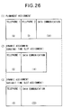
- Fig. 26 shows the arrangement upon multiplexing telephone data and data communication data using a 4-msec frame as a fundamental frame on a 64-kbps transmission path.
- the multiplexing includes a method of permanently assigning time slots to the individual media, and a method of dynamically and variably assigning time slots.
- Fig. 26 Assume that two telephone data and one data communication data are to be multiplexed. In this case, the 4-msec frame in the 64-kbps path corresponds to a 32-byte length. Numerical values in parentheses in Fig. 26 respectively indicate time slots assigned to the individual communications.
- the individual media data occupy the entire multiplexed datastream. More specifically, for example, if there is no second telephone channel data (not busy), empty data is set in that period to make communications ((1) of Fig. 26).
- the entire multiplexed line length remains the same, and the time slot of the data communication is increased accordingly ((3) of Fig. 26).
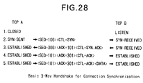
- TCP Transmission Control Protocol
- TCP handshake is attained by the sequence number, acknowledgement number, and control bits, and the transmission interval and volume of transfer data are controlled by the window size and retransmission timeout time.
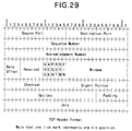
- Fig. 29 shows the format of a TCP header.
- Source Port indicates a port number of a source
- Destination Port indicates the port number of a destination.
- Sequence Number is a number that indicates the head of data to be transmitted
- Acknowledgement Number is the number of data next to the received data.
- Data Offset indicates the head of the data area in the header.
- URG is a bit indicating the validity of an urgent pointer
- ACK is a bit indicating the validity of the acknowledgement number
- PSH is a bit for instructing transfer of data to the application layer
- RST is a bit for forcibly terminating connection
- SYN is a control bit for sequence number synchronization
- FIN is a bit for terminating connection.
- Window indicates the data volume that can be transmitted without any acknowledgement.
- Checksum is the checksum of the header and data
- User Pointer is a pointer indicating the end of data requiring real-time processing.
- “Options” indicates the maximum segment length, and “Padding” is data (padding) to be set so that data can start from a 32-bit boundary. “data” is the data to be actually transferred.
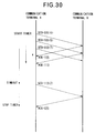
- communication terminals A 2701 and B 2702 make communications based on an FTP (File Transfer Protocol)
- these communication terminals execute the following processing.
- the transmitter basically transmits the next data after it receives ACK.
- the receiver can show the data volume that can be transmitted without any ACK, using a "Window" portion in the header format.
- Fig. 30 shows this state.
- the transmitter starts a timer in correspondence with the SEQ number upon sending each segment.
- the transmitter stops that timer when it receives ACK (the actual numerical value is SEQ number + data length) corresponding to that SEQ number. If the timer has elapsed (has reached timeout) before receiving ACK, the transmitter resends the corresponding segment.
- RFC793 Internet Engineering Task Force
- An Example Retransmission Timeout Procedure Measure the elapsed time between sending a data octet with a particular sequence number and receiving an acknowledgement that covers that sequence number (segments sent do not have to match segments received). This measured elapsed time is the Round Trip Time (RTT).
- RTT Round Trip Time
- ALPHA is a smoothing factor (e.g., .8 to .9)
- BETA is a delay variance factor (e.g., 1.3 to 2.0).
- RTT Real Time
- SRTT Green Trip Time
- the timeout time value is determined by SRTT based on actual RTT and factor BETA. That is, the TCP module cannot determine whether "RTT has changed contingently"/"RTT is going to stay stable for a while".
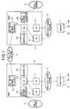
- Fig. 1 is a block diagram showing the arrangement of a multimedia communication system according to the first embodiment of the present invention
- Fig. 2 is a block diagram showing the arrangement of an adapter 1 in the multimedia communication system shown in Fig. 1
- Fig. 3 is a block diagram showing the arrangement of a node 2 in the multimedia communication system shown in Fig. 1.
- the multimedia communication system to be described in this embodiment can transmit both voice data from a telephone, which data requires real-time processing, and non-real-time LAN data which permits a delay to some extent.
- this multimedia communication system comprises a plurality of adapters 1, each of which connects a plurality of telephones and also connects a LAN terminal for, e.g., Ethernet, and a plurality of nodes 2, each of which connects a public network 5 used as a general telephone network, and exchanges various data including voice data and LAN data in correspondence with their destinations.
- Each adapter 1 is connected to the corresponding node 2 via a dedicated channel network 3, and the nodes 2 are connected to each other via a cell relay network 4.
- the cell relay network 4 transfers ATM (asynchronous transfer mode) cells using dedicated channel secondary group velocity frames defined by TTC standards JT-G703-a.
- Each adapter 1 has a function of converting voice data from the connected telephones and LAN data from the LAN terminal into a first frame by multiplexing them in time slots that are dynamically assigned using a statistical multiplexing effect, and a function of disassembling the first frame into voice and LAN data.
- the first frame is made up of a fixed-length data frame generated at predetermined periods, and the data frame includes fixed-length voice data from a plurality of channels, and variable-length LAN data.
- the LAN data is made up of one of LAN data and control data. Note that the first frame will be described in detail later.
- each adapter 1 has a telephone channel interface 11 having a plurality of ports connected to the telephones, and a LAN interface 12 connected to the LAN terminal, as shown in Fig. 2.
- the telephone channel interface 11 has various interface control circuits for the individual telephone channels such as a booster for generating a voltage required for generating a ringing signal of the telephone, a ringer (ringing signal) generator, a DTMF decoder, a hook detector, and the like.
- These circuits include a CODEC (coding/decoding) circuit for inputting/outputting voice data and compression-coded data to/from each telephone, generating compression-coded data by compression-coding the input voice data, and generating voice data by decoding the input compression-coded data. Voice data decoded by this circuit is output to the corresponding telephone.
- CODEC coding/decoding
- the CODEC circuit implements compression coding/decoding based on 16-kbps ADPCM (adaptive differential pulse code modulation) and 8-kbps CS-ACELP (conjugate-structure algebraic code-excited linear prediction coding).
- ADPCM adaptive differential pulse code modulation
- CS-ACELP conjugate-structure algebraic code-excited linear prediction coding
- the LAN interface 12 inputs/outputs LAN data, detects an IEEE802.3 frame from input LAN data, checks an MAC address and the like by a bridge function based on MAC address learning, and controls data transfer in accordance with the checking result.
- Compression-coded data from the telephone channel interface 11 and LAN data from the LAN interface 12 are output to a frame assembler/disassembler 13.
- the frame assembler/disassembler 13 generates a first frame-by multiplexing control data of the adapter 1 together with the input compression-coded data and LAN data onto dynamically assigned time slots, and outputs the first frame to an adapter controller 14.
- the frame assembler/disassembler 13 receives a first frame from the adapter controller 14, it disassembles the input first frame into compression-coded data and LAN data, and outputs them to the telephone channel interface 11 and the LAN interface 11, respectively.
- the adapter controller 14 has a CPU (not shown), which reads out a program stored in a ROM (not shown) and executes the program to control the entire adapter 1.
- This control includes transmission/reception control for transmitting the first frame from the frame assembler/disassembler 13 onto the dedicated channel network 3 via a dedicated channel interface 15, and receiving the first frame transmitted from the dedicated channel network 3 via the dedicated channel interface 15, management of the telephone channel interface 11, control of the LAN interface 12 and frame assembler/disassembler 13, and power supply control from a power supply circuit 16 to the individual blocks.
- the dedicated channel interface 15 has a function of a terminal adapter, and is connected to the dedicated channel network 3 via a DSU (data service unit) arranged on the dedicated channel network 3 side.
- DSU data service unit
- Each node 2 has a second frame assembling function of unwrapping voice data and LAN data from the first frame input via the dedicated channel network 3 and assembling a second frame for exchanging them, a third frame generation function of generating a third frame by segmenting the second frame and assembling the segments, a second frame reassembling function of reassembling a second frame from the third frame, and a first frame reassembling function of reassembling a first frame from the second frame assembled by the second frame reassembling function.
- the second and third frames will be described in detail later.
- each node 2 has a plurality of adapter interfaces 21 (AD1,..., ADn), which are connected to the dedicated channel network 3 and implement the second frame assembling function and the first frame reassembling function, a data switch (DS) 22 for exchanging the second frame, a cell relay network interface 23 that implements the third frame generation function and the second frame reassembling function, a public network interface 24 for connecting a plurality of telephone channels and the public network 5, and a controller 25 which controls the entire node 2 in accordance with a program stored in a ROM (not shown), and comprises a microprocessor and the like for performing control of the individual blocks, monitoring of the data switch 22, network management, and the like.
- the adapter interfaces 21, data switch 22, cell relay network interface 23, public network interface 24, and controller 25 are assigned inherent media numbers uniquely determined in the node 2, and these media numbers are used upon data exchange.
- Each adapter interface 21 disassembles the first frame input from the dedicated channel network 3 into voice data and LAN data, and generates second frames respectively for the voice and LAN data. These second frames are output to the data switch (DS) 22.
- the adapter interface 21 receives a second frame from the data switch (DS) 22 (to be described below), it unwraps voice or LAN data from the second frame, assembles a first frame including the voice or LAN data, and outputs the first frame onto the dedicated channel network 3.
- the data switch 22 comprises a serial crossbar switch and the like.
- the data switch 22 adds an address and the like corresponding to a unique tag, and performs switching in accordance with the added address value to exchange the second frame input as voice or LAN data.
- switching in accordance with a predetermined frame format a second frame for voice data and a second frame for LAN data including LAN and control data are exchanged.
- the cell relay network interface 23 generates a third frame by converting the second frames input from the data switch 22 into ATM cells, and outputs the third frame onto the cell relay network 4. Upon receiving a third frame from the cell relay network 4, the interface 23 extracts ATM cells from the third frame, converts the ATM cells into the second frames, and outputs them to the data switch 22.
- the public network interface 24 exchanges a voice signal, control signal, and the like with the data switch 22 unlike the cell relay network interface 23, and comprises a PBX (private branch exchange) for connecting a plurality of channels to the public network 5.
- PBX private branch exchange
- the public network interface 24 and the adapter interfaces 21 control to connect a plurality of calls at the same time in some cases.
- Fig. 4 shows the format of the first frame between each adapter 1 and node 2 via the dedicated channel network 3 in the multimedia communication system shown in Fig. 1
- Fig. 5 shows the ID format of the first frame shown in Fig. 4
- Fig. 6 shows the format of a voice frame in the first frame shown in Fig. 4
- Fig. 7 shows the VCB format of the voice frame shown in Fig. 6
- Fig. 8 shows the format of an LD/CD frame in the first frame shown in Fig. 4, Fig.
- FIG. 9 shows the LCB format of the LD/CD frame shown in Fig. 8
- Figs. 10A to 10I show an example of use of "PRI" and "STP" bits in LCB shown in Fig. 9,
- Figs. 11A to llC show examples of the data formats of the first frame in the multimedia communication system shown in Fig. 1. Note that a case will be exemplified below wherein voice data is compression-coded/decoded by 16-kbps ADPCM (Adaptive Differential Pulse Code Modulation).
- ADPCM Adaptive Differential Pulse Code Modulation
- the first frame is made up of voice data for two channels, and LAN or control data in association with the length of the datastream to be multiplexed.
- the first frame consists of a fixed-length synchronization byte SYN (to be referred to as an SYN byte hereinafter), which is located at the head of the frame and indicates synchronization information, a block format byte ID (to be referred to as an ID byte hereinafter) which follows the SYN byte and indicates format information of data blocks of the first frame, fixed-length voice frames VD1,..., VDn which follow the ID byte and indicate voice data from a plurality of channels, and variable-length LAN data LD/CD (LAN data/control data) which follows these voice frames.
- SYN byte fixed-length synchronization byte
- the SYN byte has a 1-byte data length, and is made up of 8 bits "01111110" if it is defined by HDLC (high-level data link control).
- HDLC high-level data link control
- the ID byte has a 1-byte data length, and is made up of bits respectively indicating frame identification data for identifying whether the first frame is a normal frame obtained by multiplexing voice frames and LAN data or a test frame used in, e.g., health check or the like, data indicating the number of voice channels included in the first frame, and data indicating the presence/absence of LAN data LD/CD.
- a bit KND indicating the frame identification data is allocated at the head of the byte. If this KND bit is "0", it indicates that the first frame is used as a normal frame; if the END bit is "1", it indicates that the first frame is used as a test frame. More specifically, when the adapter 1 or the like executes health check, a frame having the same format as the first frame is used as a test frame.
- An LI bit that follows the KND bit indicates the presence/absence of LAN data LD/CD, and is valid when the KND bit is "0". If the LI bit is "1", it indicates that the LAN data LD/CD is present in a predetermined time slot; if the LI bit is "0", it indicates the absence of any LAN data LD/CD.
- the number of voice channels that follows the LI bit is expressed by a bit pattern. For example, when the dedicated channel network 3 can transfer a maximum of 32 channels of voice frames at a rate of 1.5 Mbps, the number of channels of voice frames included in the first frame can be expressed by a maximum of 5 bits. In this embodiment, since the dedicated channel network 3 transfers a maximum of 2 channels of voice frames at a transfer rate of 64 kbps, the number of channels of voice frames included in the first frame is expressed by 1 bit.
- the other end-system need not be informed of any message indicating the format of the first frame to be transferred before transmission of the first frame.
- the voice frame VD after the ID byte will be explained below.
- each of the voice frames VD1,..., VDn consists of a 1-byte VCB (voice control byte) which is located at the head of the frame, and is used for identifying the compression method of voice data, and an 8-byte voice data block (compression-coded data) VDB generated at 4-ms periods by the 16-kbps ADPCM, and the data length of each voice frame is 9 bytes. Since no voice frame is transferred while a non-vocal activity period is produced after a call is connected, the voice frame length changes at 4-ms periods. In this embodiment, since the number of voice channels is a maximum of "2", the number n of voice frames included in the first frame is "2".
- the VDB is 8-byte data, but its data length varies depending on the CODEC type. For example, when 8-kbps CS-ACELP is used, the VDB has a 4-byte length.
- the VCB is assigned a bit pattern CMP which is located at the head of the byte and is used for identifying the CODEC type, and a voice channel number for specifying each telephone channel connected to the adapter 1.
- the bit pattern CMP is expressed by 1 bit.
- the LAN or control data LD/CD will be explained below.
- LAN or control data LD/CD permits a delay to some extent unlike voice data that requires real-time processing, it is transferred independently of 4 ms as the transfer period of the first frame. More specifically, the LAN or control data LD/CD is divided into data having a predetermined data length, as needed, and one or a plurality of divided data are transferred while being superposed on first frames which are sequentially generated. For example, when a transfer request of a total of two frames, e.g., two IEEE802.3 frames or one IEEE802.3 frame and one control data frame is generated, the two frames must be segmented into a plurality of data, so that these divided data are transferred while being superposed onto first frames.
- the usable length of the LAN data LD/CD also changes.
- the LAN or control data LD/CD is added a 1-byte LCB (LAN/control data control byte) for controlling division, as shown in Fig. 8.
- this LCB is made up of an INF bit located at the head of the byte, PRI and STP bits that follow the INF bit, and a sequence number that follows the STP bit.
- the INF bit identifies whether data in this field is user's LAN data or control data between the adapter 1 and node 2. If this bit is "0”, it indicates LAN data; if this bit is "1", it indicates control data.
- the PRI bit indicates data priority, and is used, for example, when data to be urgently sent in terms of system performance is generated during transfer of data having a considerably long data length, and the data must be sent by interrupting the transfer of the long data, or when performance is expected to deteriorate in terms of delay in call control of the telephone. If the PRI bit assumes a value "0", it indicates low priority; if it assumes a value "1", it indicates high priority.
- the STP bit indicates the last block of the divided data. If this bit is "1", it indicates the last block of the divided data; if this bit is "0", it indicates a block other than the last block.
- the sequence number that follows the STP bit is toggle information for monitoring continuity of the divided LAN/CD data.
- Figs. 10A to 10I show an example wherein control data with high priority for four cycles interrupt the first frame at 4-ms periods during transfer of LAN or control data LD/CD with low priority.
- the PRI and STP bits are respectively set at "0" (see Figs. 10A and 10B).
- the PRI bit for the interrupting data is set at "1" (see Figs. 10C, 10D, 10E, and 10F), and in the last block of that data, the STP bit is set at "1" while holding the PRI bit at "1” (see Fig. 10F).
- the adapter 1 and node 2 transfer first frames via the dedicated channel network 3 while changing its data format at 4-ms periods in correspondence with the number of voice channels, the presence/absence of voice frames controlled by the non-vocal activity control, and the presence/absence of LAN data LD/CD.
- first frame format example 1 shown in Fig. 11A is used.
- first frame format example 2 shown in Fig. 11B is used.
- first frame format example 3 shown in Fig. 11C is used.
- the transfer volume of LAN data LD/CD changes in correspondence with the number of voice channels and the presence/absence of voice frames, and can be increased as the number of voice channels decreases or when no voice frame is present.
- Fig. 23 depicts changes in transfer volume of voice data and LAN data LD/CD in units of frames.
- Fig. 23 the voice data and LAN data LD/CD are illustrated using different patterns.
- voice frames for two channels are transferred as in Fig. 11A.
- transfer of voice frames for the two channels are simultaneously stopped, and LAN data occupy all time slots, as in Fig. 11C.
- Fig. 11B a voice frame for one of the two channels is transferred.
- both voice frames for the two channels and LAN data LD/CD are transferred, as in Fig. 11A.
- a voice frame for one of the two channels is transferred, and the remaining time slots are used for transferring LAN data LD/CD, as in Fig. 11B.
- First frames for the subsequent two cycles are used by voice frames for the two channels and LAN data LD/CD as in Fig. 11A.
- the transfer volumes of voice frames and LAN data LD/CD dynamically change in a predetermined span of time.
- the first frame is added information (the ID byte in this embodiment) indicating the number of voice channels (VD) and the presence/absence of LAN data LD/CD, the other end-system need not be notified of a change in format of the first frame in advance.
- Fig. 12 is a block diagram showing the arrangement of each adapter interface 21 in the node 2 shown in Fig. 3
- Figs. 13A and 13B show the formats of voice packets (second frames) exchanged by the data switch 22 in the node 2 shown in Fig. 3
- Figs. 14A and 14B show the formats of LAN/CD packets (second frames) exchanged by the data switch 22 in the node 2 shown in Fig. 3, Fig.
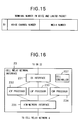
- Fig. 15 shows the data format of a terminal number included in the voice and LAN/CD packets
- Fig. 16 is a block diagram showing the arrangement of the cell relay network interface 23 in the node 2 shown in Fig. 3
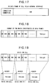
- Fig. 17 shows the format of a VD data frame assembled by the cell relay network interface 23 shown in Fig. 16
- Fig. 18 shows the format of a PDU that concatenates the VD data frames shown in Fig. 17,
- Fig. 19 shows an assembling example of voice ATM cells
- Fig. 20 shows the format of a LAN data LD/CD frame assembled by the cell relay network interface 23 shown in Fig. 16
- Fig. 21 shows the format of a PDU that concatenates the LAN data LD/CD frames shown in Fig. 20, and
- Fig. 22 shows an assembling example of LAN ATM cells.
- each adapter interface 21 in the node 2 and the sequence until conversion into a second frame used for exchanging the received first frame will be described below with reference to Figs. 12 to 15.
- a first frame When a first frame is transferred from one adapter 1 via the dedicated channel network 3, it is received by the corresponding adapter interface 21 of the node 2.
- a dedicated channel network interface 211 In the adapter interface 21, as shown in Fig. 12, a dedicated channel network interface 211 unwraps data, and reconstructs a first frame (shown in Fig. 4) at 4-ms periods.
- the first frame is supplied to a frame assembler/disassembler 212. Since the first frame includes voice frames (VD1,..., VDn; shown in Fig. 6) and LAN or control data LD/CD, as described above, the frame assembler/disassembler 212 disassembles the first frame into the voice frames and LAN or control data LD/CD frames on the basis of the ID byte in the first frame.
- Each voice frame is supplied to a voice frame processor 213, each LAN data is supplied to a LAN data processor 214, and each control data is supplied to a control data processor 215.
- the voice frame processor 213 Upon receiving the voice frame, the voice frame processor 213 converts the VCB byte (shown in Fig. 7) at the head of this voice frame into a terminal number which includes data including a channel number in the VCB byte, and a media number assigned to each block in the node 2, and generates a voice packet (a second frame of voice data) including this terminal number.
- the voice packet is made up of the terminal number and VDB (shown in Fig. 6), as shown in Fig. 13A. Note that the format of the terminal number will be explained later.
- the LAN or control data processor 214 or 215 stores LAN or control data LD or CD stripped from the first frame, and assembles a plurality of stored data using the LCB byte (shown in Fig. 8), thereby reconstructing a LAN data LD frame (IEEE802.3 frame) or control data CD frame. Each reconstructed frame is added a terminal number and user ID, as shown in Fig. 14A, thus generating an LD/CD packet (a second frame of LAN data).
- This user ID represents an ID for specifying a system supervisor who uses control data, when data included in the packet is the control data. In case of LAN data, the user ID represents an ID assigned in units of LAN users.
- the terminal number added to each of the second frames of the voice and LD/CD packets is made up of a DI bit, voice channel number, and a media number assigned to each block in the node 2, as shown in Fig. 15.
- the DI bit indicates terminal identification information for identifying whether a packet added this terminal number is a voice or LD/CD packet, and is set at "0" for a voice packet or is set at "1" for an LD/CD packet.
- the voice channel number is the same as that indicated by the VCB shown in Fig. 7. If the DI bit is "1", the area of the voice channel number becomes an empty data area, and is ignored at the data receiver.
- Packets generated by the voice frame processor 213, LAN data processor 214, and control data processor 215 are supplied to a DS interface 216.
- the DS interface 216 packages the input packets into packets that can be exchanged by the data switch 22. More specifically, a voice packet is encapsulated into a voice packet which is added a DS address at the head of the packet, and EOP (end of packet) at the end of the packet, as shown in Fig. 13B. Likewise, an LD/CD packet is encapsulated into an LD/CD packet which is added a DS address at the head of the packet, and EOP (end of packet) at the end of the packet, as shown in Fig. 14B.
- the DS address indicates an exchange destination required in packet exchange by the data switch 22, and the EOP is a bit which serves as both identification of the end of the packet, and a CRC of block check for the packet.
- the DS interface 216 packages the packets supplied from the voice frame processor 213, LAN data processor 214, and control data processor 215 into packets that can be exchanged by the data switch 22, and outputs the obtained packets to the data switch 22.
- the processing for inputting, converting, and outputting a voice packet is executed within a 4-ms period, and the processing for inputting, converting, and outputting a LAN/CD packet is executed using an interval between adjacent voice packet processing periods.
- a DS controller 217 executes control and management for the individual blocks including the control for this packet processing of the DS interface 216.
- the DS controller 217 exchanges data used in the control of the adapter interface 21 with other controllers as needed.
- the data switch 22 Upon receiving a packet from the DS interface 216, the data switch 22 performs switching to output that packet to the exchange destination on the basis of the DS address added to the packet. Since the destination which received the packet does not require any DS address, the switch 22 deletes the DS address. In this manner, the DS address is used as a transiently valid value.
- Packets are exchanged: from one of the adapter interfaces 21 to another adapter interface 21 in a single node 2; from one of the adapter interfaces 21 to the cell relay network interface 23 or from one of the adapter interfaces 21 to the public network interface 24 in a single node 2; from the cell relay network interface 23 to one of the adapter interfaces 21 or from the public network interface 24 to one of the adapter interfaces 21 in a single node 2.
- the adapter interface 21 when a packet is sent from one of the adapter interfaces 21 to another adapter interface 21 in a single node 2 via the data switch 22, the adapter interface 21 that is to receive the packet executes processing opposite to that for outputting a packet to the data switch 22. That is, when the adapter interface 21 receives a voice packet, it inversely converts the terminal number into the VCB byte shown in Fig. 6 using a table or the like prepared in advance, and generates a voice packet shown in Fig. 13A. This voice packet is packaged into a first frame which is then output to the corresponding adapter 1 via the dedicated channel network 3. The adapter 1 connects a call to the corresponding channel, and decodes and outputs voice data.
- the adapter interface 21 Upon receiving an LD/CD packet, the adapter interface 21 checks the user ID and terminal number, then assembles a first frame using that LD/CD packet, and outputs the first frame to the corresponding adapter 1.
- the adapter 1 reconstructs the data as an IEEE802.3 frame, and outputs that frame to the destination via an Ethernet interface.
- data included in the first frame is control data CD
- the adapter 1 executes internal control in accordance with that data.
- the public network interface 24 checks the destination port connected to the public network 5 on the basis of the terminal number added to that packet using a table or the like, decodes the voice data block VDB, and outputs the decoded voice data onto the public network 5 via the PBX.
- the packet When a packet is sent from the adapter interface 21 to the cell relay network interface 23 via the data switch 22, the packet is fetched by a DS interface 231, as shown in Fig. 16.
- the DS interface 231 Upon fetching a voice packet, the DS interface 231 deletes its DS address, and thereafter, outputs the voice packet to a VDF processor 232.
- the interface 231 Upon fetching an LD/CD packet, the interface 231 deletes its DS address, and thereafter, outputs a LAN packet to an LDF processor 233 and a control packet to a CDF processor 234.
- the VDF, LDF, and CDF processors 232, 233, and 234 execute ATM cell formation processing required for outputting data in the received packets onto the cell relay network 4. Since this ATM cell formation processing concatenates such data and outputs the concatenated data onto the cell relay network, the control data volume is required to be minimized, and the individual processors execute processing to meet such requirement.
- the VDF processor 232 converts the terminal number included in the received voice packet (shown in Fig. 13A) into a 1-byte connection number (CN) using a table prepared in advance, and creates a VD data frame which is added this connection number at the head thereof.
- the terminal number is information required for switching control of the data switch 22 in the node 2. However, since information to be added after a call connection must be minimized for the cell relay network 4 which is used at a limited service rate or less, the terminal number is converted into the connection number.
- the table stores correspondence between the terminal number and connection number, and is generated in advance upon connecting a call between the nodes.
- the VD data frame is made up of a connection number (CN) and a VDB that follows the CN.
- CN connection number
- VDB VDB
- the VD data frames are stored at predetermined periods, and a plurality of stored VD data frames are concatenated and are adapted to a PDU (protocol data unit) as a data block unit on the communication protocol.
- the PDU that concatenates the VD data frames is made up of a plurality of VD data frames and a trailer used for adjusting the data length of the PDU, as shown in Fig. 18.
- the data length-of the PDU is set at an integer multiple of 48 bytes as the payload field length of an ATM cell, and the trailer is added to the end of the PUD, so that the data length of the PDU equals an integer multiple of 48 bytes.
- the PDU that concatenates the VD data frames is output to an ATM network interface 235.
- the ATM network interface 235 breaks up the PDU that concatenates the VD data frames into 48-byte payloads to generate ATM cells complying with user service requirements. More specifically, as shown in Fig. 19, the PDU that concatenates the VD data frames are divided into a plurality of 48-byte payloads, and a 5-byte header that stores a prescribed value is added to each divided payload.
- the divided payloads with headers are output onto the cell relay network 4 as voice ATM cells (third frames).
- the LDF or CDF processor 233 or 234 Upon receiving an LD/CD packet shown in Fig. 14A, the LDF or CDF processor 233 or 234 converts the packet into a LAN data LD/CD frame basically including a user ID and a LAN data LD frame (IEEE802.3 frame) or control data CD frame, since the terminal number of that packet is not required in the cell relay network 4. More specifically, as shown in Fig. 20, the LAN data LD/CD frame is made up of a user ID (UI) at the head of the frame, and a LAN data LD frame (IEEE802.3 frame)/control data CD frame (L/CF) that follows the UI.
- UI user ID
- L/CF control data CD frame
- LAN data LD/CD frames are stored at predetermined periods, and a plurality of stored frames are concatenated and converted into a PDU.
- the PDU is made up of a plurality of LAN data LD/CD frames and a trailer for adjusting the data length of the PDU, as in the PDU that concatenates VD data frames, and the data length of the PDU is adjusted to an integer multiple of 48 bytes as the payload area length of an ATM cell by adding the trailer.
- the PDU that concatenates the LAN data LD/CD frames is output to the ATM network interface 235, which divides the PDU that concatenates the LAN data LD/CD frames into 48-byte payloads to generate ATM cells complying with user service requirements. More specifically, as shown in Fig. 22, the PDU that concatenates the LAN data LD/CD frames are divided into a plurality of 48-byte payloads, and a 5-byte header that stores a prescribed value is added to each divided payload. The divided payloads with headers are output onto the cell relay network 4 as LAN ATM cells (third frames).
- LAN ATM cells are transmitted while transmitting/receiving voice ATM cells in real time, thus maintaining real-time characteristics of voice data.
- a destination node 2 When a destination node 2 receives ATM cells sent via the cell relay network 4, that node 2 converts the received ATM cells into corresponding voice frames or LAN data frames by processing opposite to the above-mentioned ATM cell transmission, assembles a first frame using the converted frames, and transfers the first frame to the corresponding adapter 1 and the like.
- the adapter 1 as the transmitter converts voice data from the connected telephones and LAN data from the LAN terminal into a first frame by multiplexing them in time slots which are dynamically assigned using statistical multiplexing, and transfers the first frame to the node 2 via the dedicated channel network 3 without informing the destination of the format of the first frame in advance.
- the node 2 disassembles the input first frame into voice data and LAN data, and assembles a voice packet or LD/CD packet (second frame) using these data to exchange such packet. Thereafter, the node 2 disassembles and reassembles that packet to generate voice or LAN ATM cells (third frame) and transfers them to the destination node 2 via the cell relay network 4.
- the node 2 Upon receiving the ATM cells sent via the cell relay network 4, the node 2 converts the received ATM cells into voice or LAN data frames to assemble a first frame by processing opposite to the above-mentioned ATM cell transmission, and transfers the first frame to the corresponding adapter 1 and the like.
- data can be transmitted by simultaneously connecting multipoints.
- a connection to the public network 5 can be done, and voice data can be used while maintaining its real-time characteristics upon transmitting LAN data.
- a retransmission timer set between the adapter 1 and node 2 will be explained below.
- Fig. 24 is a flow chart showing the control sequence of the adapter controller 14 in the adapter 1 and the DS controller 217 of the adapter interface 21 in the node 2
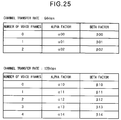
- Fig. 25 is an explanatory view showing tables for determining the retransmission timeout time.
- this table is stored in memories such as the RAMs of the adapter controller 14 and the DS controller 217. These memories also store the number of voice frames used in the first frame.
- step S101 corresponds to a state wherein data from a higher layer is being transmitted. For example, in this state, FTP communications are in progress from the adapter 1 to the node 2 or vice versa. Note that the sequence before this step is the same as that in the prior art, and a detailed description thereof will be omitted.
- step S102 the presence/absence of a request or message (event) to the adapter controller 14 or DS controller 217 is checked. If the detected request or message is not a data transmission request, other event processing is done in step S211.
- the retransmission timeout time is determined on the basis of the transfer rate of the transmission path used and the number of voice frames using the tables shown in Fig. 25 (step S103). Note that the number of voice frames is written by an application program that controls a telephone call in a portion of the above-mentioned memory. Also, the adapter controller 14 or DS controller 217 can look up this memory area.
- step S104 a first frame is output.
- the retransmission timeout time determined in step S103 is set in a timer (step S105).
- step S106 It is then checked if transmission for the size of the first frame is complete (step S106). If the transmission is complete, the control transmits to an ACK wait state (step S201). On the other hand, if the transmission is not complete yet, the control returns to step S102 to continue data transmission.
- step S102 determines whether the event is other than the data transmission request. If it is determined in step S102 that the event is other than the data transmission request, the same processing as in the prior art is done, and a detailed description thereof will be omitted.
- values upon multiplexing a maximum of two channels of telephones in case of a 64-kbps channel and a maximum of four channels of telephones in case of a 128-kbps channel to a single IP packet communications are prepared. These values are set by reflecting some communication results (communication results without frequently reaching timeout states).
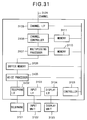
- Fig. 31 is a block diagram showing the arrangement of a multiplexing communication apparatus in this embodiment.
- a controller 3101 comprises, e.g., a microprocessor, and controls the entire apparatus.
- a telephone interface 3102 accommodates an analog telephone or ISDN telephone 3121.
- An input interface 3103 receives an input signal from the user via an input unit 3122 such as a keyboard, mouse, or the like.
- a display interface 3104 interfaces a display unit 3123, and a voice data processor 3105 encodes/decodes voice data in case of, e.g., an analog telephone.
- a buffer memory 3106 temporarily stores various data.
- a multiplexing processor 3107 multiplexes telephone data with other application data.
- a channel controller 3108 controls a channel that connects its own apparatus and the apparatus on the other end.
- a channel interface 3109 interfaces a channel.
- a memory 3110 stores the number of telephone channels, and the like, and a memory 3111 stores control information including a program that describes the operation of the controller 3101, and the like.
- Fig. 32 is a flow chart showing the control sequence of a TCP module as a portion of control information
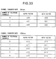
- Fig. 33 is an explanatory view showing tables for determining the retransmission timeout time.
- Step S3201 corresponds to a state wherein data from a higher layer is being transmitted.
- the user is performing FTP communications using the input unit 3122 and display unit 3123. Note that the sequence before this step is the same as that in the prior art, and a detailed description thereof will be omitted.
- step S3202 the presence/absence of a request or message (event) to this module is checked. If the detected request or message is not a data transmission request, other event processing is done in step S3208.
- the retransmission timeout time is determined on the basis of the transfer rate of the transmission path used and the number of telephone channels using the tables shown in Fig. 33 (step S3203). Note that the number of telephone channels is written in a portion of the memory 3110 by an application program that controls a telephone call.
- the TCP module can look up that area of the memory 3110.
- step S3204 a header shown in Fig. 29 is formed and output.
- the retransmission timeout time determined in step S3203 is set in a timer (step S3205).
- step S3206 It is then checked if transmission for the window size is complete (step S3206). If the transmission is complete, the control transmits to an ACK wait state (step S3207). On the other hand, if the transmission is not complete yet, the control returns to step S3202 to continue the data transmission.
- step S3202 if it is determined in step S3202 that the event is other than the data transmission request, the same processing as in the prior art is done, and a detailed description thereof will be omitted.
- values upon multiplexing a maximum of two channels of telephones in case of a 64-kbps channel and a maximum of four channels of telephones in case of a 128-kbps channel to a single IP packet communications are prepared. These values are set by reflecting some communication results (communication results without frequently reaching timeout states).
- multipoints can be connected at the same time.
- real-time and non-real-time data can be simultaneously transmitted while maintaining the real-time characteristics of real-time data.
- the timeout time used for determining retransmission can be set at an appropriate value on the basis of the time slot assignment.
- a message indicating changes in format of a communication frame need not be supplied to the other end.
Abstract
Description
An Example Retransmission Timeout Procedure
Measure the elapsed time between sending a data octet with a particular sequence number and receiving an acknowledgement that covers that sequence number (segments sent do not have to match segments received). This measured elapsed time is the Round Trip Time (RTT). Next compute a Smoothed Round Trip Time (SRTT) as:
Claims (58)
- A communication system having first and second communication apparatuses, and communicates a communication frame obtained by time-division multiplexing a plurality of communication data,
said first communication apparatus (1), characterized by comprising:characterized by comprising:first reception means (11, 12) for receiving first and second communication data;recognition means (14) for recognizing whether said first reception means (11, 12) receives the first or second communication data;first communication frame assembling means (13) for assembling a time-division multiplexed first communication frame using the communication data received by said first reception means (11, 12), and adding information indicating a format of the first communication frame to the first communication frame on the basis of a recognition result of said recognition means (14); andfirst transmission means (15) for transmitting the first communication frame assembled by said first communication frame assembling means to said second communication apparatus(2), andsaid second communication apparatus (2),second reception means (21) for receiving the first communication frame transmitted from said first transmission means (15);checking means (25) for checking the format of the first communication frame received by said second reception means (21) on the basis of the information added to the first communication frame received by said second reception means (21); andacquisition means (22) for acquiring the communication data from the first communication frame received by said second reception means (21), on the basis of a checking result of said checking means (25). - The system according to claim 1, wherein the information indicating the format of the first communication frame includes information indicating presence/absence of the first or second communication data.
- The system according to claim 1, wherein said first reception means (11, 12) can receive a plurality of first communication data, and
the information indicating the format of the first communication frame includes the number of first communication data included in the first communication frame. - The system according to claim 1, wherein the first communication data is real-time data.
- The system according to claim 1, wherein the second communication data is non-real-time data.
- The system according to claim 1, wherein said recognition means (14) recognizes presence/absence of reception of the first communication data by said first reception means (11, 12), and
said first communication frame assembling means (13) assembles first communication frames with different formats on the basis of the presence/absence of reception of the first communication data. - The system according to claim 1, wherein said first reception means (11, 12) can receive a plurality of first communication data, and
said first communication frame assembling means (13) assembles first communication frames with different formats in accordance with the number of first communication data received by said first reception means (11, 12). - The system according to claim 1, wherein said first communication apparatus (1) comprises determination means (14) for determining time information used for retransmitting a communication frame transmitted by said first transmission means (15), on the basis of the recognition result of said recognition means (14).
- The system according to claim 8, wherein said recognition means (14) recognizes presence/absence of reception of the first communication data by said first reception means (11, 12), and
said determination means (14) determines the time information on the basis of the presence/absence of reception of the first communication data. - The system according to claim 8, wherein said first reception means (11, 12) can receive a plurality of first communication data, and
said determination means (14) determines the time information on the basis of the number of first communication data received by said first reception means (11, 12). - The system according to claim 1, wherein said second communication apparatus (2) comprises second transmission means (23) for transmitting the communication data acquired by said acquisition means (22) to a third communication apparatus.
- The system according to claim 11, wherein said second transmission means (23) comprises second communication frame assembling means for assembling a second communication frame using the communication data acquired by said acquisition means (22).
- A communication apparatus for communicating a communication frame obtained by time-division multiplexing a plurality of communication data, characterized by comprising:reception means (11, 12) for receiving first and second communication data;recognition means (14) for recognizing whether said first reception means (11, 12) receives the first or second communication data;communication frame assembling means (13) for assembling a time-division multiplexed communication frame using the communication data received by said reception means (11, 12), and adding information indicating a format of the communication frame to the communication frame on the basis of a recognition result of said recognition means (14); andtransmission means (15) for transmitting the communication frame assembled by said communication frame assembling means (13) to another communication apparatus.
- The apparatus according to claim 13, wherein the information indicating the format of the communication frame includes information indicating presence/absence of the first or second communication data.
- The apparatus according to claim 13, wherein said reception means (11, 12) can receive a plurality of first communication data, and
the information indicating the format of the communication frame includes the number of first communication data included in the communication frame. - The apparatus according to claim 13, wherein the first communication data is real-time data.
- The apparatus according to claim 13, wherein the second communication data is non-real-time data.
- The apparatus according to claim 13, wherein said recognition means (14) recognizes presence/absence of reception of the first communication data by said reception means (11, 12), and
said communication frame assembling means (13) assembles communication frames with different formats on the basis of the presence/absence of reception of the first communication data. - The apparatus according to claim 13, wherein said reception means (11, 12) can receive a plurality of first communication data, and
said communication frame assembling means (13) assembles communication frames with different formats in accordance with the number of first communication data received by said reception means (11, 12). - The apparatus according to claim 13, further comprising determination means (14) for determining time information used for retransmitting a communication frame transmitted by said transmission means (15), on the basis of the recognition result of said recognition means (14).
- The apparatus according to claim 20, wherein said recognition means (14) recognizes presence/absence of reception of the first communication data by said reception means (11, 12), and
said determination means (14) determines the time information on the basis of the presence/absence of reception of the first communication data. - The apparatus according to claim 20, wherein said reception means (11, 12) can receive a plurality of first communication data, and
said determination means (14) determines the time information on the basis of the number of first communication data received by said reception means (11, 12). - A communication apparatus for receiving a communication frame obtained by time-division multiplexing a plurality of communication data, characterized by comprising:reception means (21) for receiving a communication frame which is obtained by time-division multiplexing at least first or second communication data and is transmitted from another communication apparatus;checking means (25) for checking a format of the communication frame received by said reception means (21) on the basis of information which is added to the communication frame received by said reception means (21), and indicates the format of the communication frame; andacquisition means (22) for acquiring the communication data from the communication frame received by said reception means (21), on the basis of a checking result of said checking means (25).
- The apparatus according to claim 23, wherein the information indicating the format of the communication frame includes information indicating presence/absence of the first or second communication data.
- The apparatus according to claim 23, wherein the information indicating the format of the communication frame includes the number of first communication data included in the communication frame.
- The apparatus according to claim 23, wherein the first communication data is real-time data.
- The apparatus according to claim 23, wherein the second communication data is non-real-time data.
- The apparatus according to claim 23, further comprising transmission means (23) for transmitting the communication data acquired by said acquisition means (22) to another communication apparatus.
- The apparatus according to claim 28, wherein said transmission means (23) comprises communication frame assembling means (232, 233, 234) for assembling a communication frame with a format different from the format of the communication frame received by said reception means (21) using the communication data acquired by said acquisition means (22).
- A method of controlling a communication system having first and second communication apparatuses, and communicates a communication frame obtained by time-division multiplexing a plurality of communication data,said first communication apparatus comprising:the first reception step of receiving first and second communication data;the recognition step of recognizing whether the first or second communication data is received in the first reception step;the first communication frame assembling step of assembling a time-division multiplexed first communication frame using the communication data received in the first reception step, and adding information indicating a format of the first communication frame to the first communication frame on the basis of a recognition result in the recognition step; andthe first transmission step of transmitting the first communication frame assembled in the first communication frame assembling step to said second communication apparatus, andsaid second communication apparatus comprising:the second reception step of receiving the first communication frame transmitted from said first communication apparatus;the checking step of checking the format of the first communication frame received in the second reception step on the basis of the information added to the first communication frame received in the second reception step; andthe acquisition step of acquiring the communication data from the first communication frame received in the second reception step, on the basis of a checking result in the checking step.
- The method according to claim 30, wherein the information indicating the format of the first communication frame includes information indicating presence/absence of the first or second communication data.
- The method according to claim 30, wherein a plurality of first communication data can be received in the first reception step, and
the information indicating the format of the first communication frame includes the number of first communication data included in the first communication frame. - The method according to claim 30, wherein the first communication data is real-time data.
- The method according to claim 30, wherein the second communication data is non-real-time data.
- The method according to claim 30, wherein the recognition step includes the step of recognizing presence/absence of reception of the first communication data in the first reception step, and
the first communication frame assembling step includes the step of assembling first communication frames with different formats on the basis of the presence/absence of reception of the first communication data. - The method according to claim 30, wherein a plurality of first communication data can be received in the first reception step, and
the first communication frame assembling step includes the step of assembling first communication frames with different formats in accordance with the number of first communication data received in the first reception step. - The method according to claim 30, wherein said first communication apparatus comprises the determination step of determining time information used for retransmitting a communication frame transmitted in the first transmission step, on the basis of the recognition result in the recognition step.
- The method according to claim 37, wherein the recognition step includes the step of recognizing presence/absence of reception of the first communication data in the first reception step, and
the determination step includes the step of determining the time information on the basis of the presence/absence of reception of the first communication data. - The method according to claim 37, wherein a plurality of first communication data can be received in the first reception step, and
the determination step includes the step of determining the time information on the basis of the number of first communication data received in the first reception step. - The method according to claim 30, wherein said second communication apparatus comprises the second transmission step of transmitting the communication data acquired in the acquisition step to a third communication apparatus.
- The method according to claim 40, wherein the second transmission step comprises the second communication frame assembling step of assembling a second communication frame using the communication data acquired in the acquisition step.
- A method of controlling a communication apparatus for communicating a communication frame obtained by time-division multiplexing a plurality of communication data, comprising:the reception step of receiving first and second communication data;the recognition step of recognizing whether the first or second communication data is received in the reception step;the communication frame assembling step of assembling a time-division multiplexed communication frame using the communication data received in the reception step, and adding information indicating a format of the communication frame to the communication frame on the basis of a recognition result in the recognition step; andthe transmission step of transmitting the communication frame assembled in the communication frame assembling step to another communication apparatus.
- The method according to claim 42, wherein the information indicating the format of the communication frame includes information indicating presence/absence of the first or second communication data.
- The method according to claim 42, wherein a plurality of first communication data can be received in the reception step, and
the information indicating the format of the communication frame includes the number of first communication data included in the communication frame. - The method according to claim 42, wherein the first communication data is real-time data.
- The method according to claim 42, wherein the second communication data is non-real-time data.
- The method according to claim 42, wherein the recognition step includes the step of recognizing presence/absence of reception of the first communication data in the reception step, and
the communication frame assembling step includes the step of assembling communication frames with different formats on the basis of the presence/absence of reception of the first communication data. - The method according to claim 42, wherein a plurality of first communication data can be received in the reception step, and
the communication frame assembling step includes the step of assembling communication frames with different formats in accordance with the number of first communication data received in the reception step. - The method according to claim 42, further comprising the determination step of determining time information used for retransmitting a communication frame transmitted in the transmission step, on the basis of the recognition result in the recognition step.
- The method according to claim 49, wherein the recognition step includes the step of recognizing presence/absence of reception of the first communication data received in the reception step, and
the determination step includes the step of determining the time information on the basis of the presence/absence of reception of the first communication data. - The method according to claim 49, wherein a plurality of first communication data can be received in the reception step, and
the determination step includes the step of determining the time information on the basis of the number of first communication data received in the reception step. - A method of controlling a communication apparatus for receiving a communication frame obtained by time-division multiplexing a plurality of communication data, comprising:the reception step of receiving a communication frame which is obtained by time-division multiplexing at least first or second communication data and is transmitted from another communication apparatus;the checking step of checking a format of the communication frame received in the reception step on the basis of information which is added to the communication frame received in the reception step, and indicates the format of the communication frame; andthe acquisition step of acquiring the communication data from the communication frame received in the reception step, on the basis of a checking result in the checking step.
- The method according to claim 52, wherein the information indicating the format of the communication frame includes information indicating presence/absence of the first or second communication data.
- The method according to claim 52, wherein the information indicating the format of the communication frame includes the number of first communication data included in the communication frame.
- The method according to claim 52, wherein the first communication data is real-time data.
- The method according to claim 52, wherein the second communication data is non-real-time data.
- The method according to claim 52, further comprising the transmission step of transmitting the communication data acquired in the acquisition step to another communication apparatus.
- The method according to claim 57, wherein the transmission step comprises the communication frame assembling step of assembling a communication frame with a format different from the format of the communication frame received in the reception step using the communication data acquired in the acquisition step.
Applications Claiming Priority (6)
| Application Number | Priority Date | Filing Date | Title |
|---|---|---|---|
| JP31862096 | 1996-11-15 | ||
| JP31862096A JP3667012B2 (en) | 1996-11-15 | 1996-11-15 | Multimedia communication method and communication apparatus |
| JP318620/96 | 1996-11-15 | ||
| JP9017878A JPH10210078A (en) | 1997-01-16 | 1997-01-16 | Multiplex communication equipment |
| JP1787897 | 1997-01-16 | ||
| JP17878/97 | 1997-01-16 |
Publications (2)
| Publication Number | Publication Date |
|---|---|
| EP0843442A2 true EP0843442A2 (en) | 1998-05-20 |
| EP0843442A3 EP0843442A3 (en) | 1999-09-08 |
Family
ID=26354466
Family Applications (1)
| Application Number | Title | Priority Date | Filing Date |
|---|---|---|---|
| EP97309129A Withdrawn EP0843442A3 (en) | 1996-11-15 | 1997-11-13 | Communication system for communicating a plurality of time-division multiplexed data, and control method therefor |
Country Status (2)
| Country | Link |
|---|---|
| US (1) | US6625166B2 (en) |
| EP (1) | EP0843442A3 (en) |
Cited By (2)
| Publication number | Priority date | Publication date | Assignee | Title |
|---|---|---|---|---|
| WO2001091387A1 (en) * | 2000-05-26 | 2001-11-29 | Photonixnet Kabushiki Kaisha | Statistical multiplexer |
| WO2002089427A1 (en) * | 2001-05-02 | 2002-11-07 | Inesc Inovação - Instituto De Novas Tecnologias | Data communication in frame mode for differenciated services |
Families Citing this family (27)
| Publication number | Priority date | Publication date | Assignee | Title |
|---|---|---|---|---|
| US6963361B1 (en) * | 1998-02-24 | 2005-11-08 | Canon Kabushiki Kaisha | Image sensing method and apparatus capable of performing vibration correction when sensing a moving image |
| FI108824B (en) * | 1998-06-03 | 2002-03-28 | Nokia Corp | Data transfer procedures in a telecommunications system |
| US7593380B1 (en) * | 1999-03-05 | 2009-09-22 | Ipr Licensing, Inc. | Variable rate forward error correction for enabling high performance communication |
| EP1077559A1 (en) * | 1999-08-17 | 2001-02-21 | Telefonaktiebolaget Lm Ericsson | Method and device for determining a time-parameter |
| US6751698B1 (en) * | 1999-09-29 | 2004-06-15 | Silicon Graphics, Inc. | Multiprocessor node controller circuit and method |
| JP2001285400A (en) * | 2000-03-29 | 2001-10-12 | Kddi Corp | Correcting method of traffic statistics information |
| US9444785B2 (en) | 2000-06-23 | 2016-09-13 | Cloudshield Technologies, Inc. | Transparent provisioning of network access to an application |
| US8204082B2 (en) * | 2000-06-23 | 2012-06-19 | Cloudshield Technologies, Inc. | Transparent provisioning of services over a network |
| US7003555B1 (en) * | 2000-06-23 | 2006-02-21 | Cloudshield Technologies, Inc. | Apparatus and method for domain name resolution |
| US7032031B2 (en) * | 2000-06-23 | 2006-04-18 | Cloudshield Technologies, Inc. | Edge adapter apparatus and method |
| US20020021699A1 (en) * | 2000-08-15 | 2002-02-21 | Shih-Pin Hsiao | Network device and method for controling quality of service |
| US6772375B1 (en) * | 2000-12-22 | 2004-08-03 | Network Appliance, Inc. | Auto-detection of limiting factors in a TCP connection |
| US7411966B2 (en) * | 2001-03-16 | 2008-08-12 | Siemens Aktiengesellschaft | Method and system for coupling data networks |
| US8089888B2 (en) * | 2001-12-10 | 2012-01-03 | Qualcomm Incorporated | Method and apparatus for testing traffic and auxiliary channels in a wireless data communication system |
| US8156535B2 (en) * | 2002-02-12 | 2012-04-10 | Finsar Corporation | Data rate compression device for cable television return path using bandpass puncturing |
| US7725036B2 (en) * | 2002-02-12 | 2010-05-25 | Finisar Corporation | Efficient transmission of digital return path data in cable television return path |
| US7751718B2 (en) * | 2002-02-12 | 2010-07-06 | Finisar Corporation | Efficient transmission of digital return path data in cable television return path |
| US20040213350A1 (en) * | 2003-04-24 | 2004-10-28 | Frith Peter J. | Interface format for PCM and DSD devices |
| JP2005244897A (en) * | 2004-02-27 | 2005-09-08 | Fujitsu Ltd | Communication method with reliability and apparatus therefor |
| US8032916B2 (en) * | 2004-05-12 | 2011-10-04 | Finisar Corporation | Single master clock control of Ethernet data transfer over both a cable TV return path and an Ethernet forward path |
| US7519078B2 (en) * | 2004-05-12 | 2009-04-14 | Finisar Corporation | Automated ethernet configuration of CATV network |
| US7765576B2 (en) * | 2004-05-12 | 2010-07-27 | Finsiar Corporation | Changing communication mode in a CATV pathway using mute commands |
| US8503340B1 (en) * | 2004-07-11 | 2013-08-06 | Yongyong Xu | WiFi phone system |
| JP2007143113A (en) * | 2005-10-19 | 2007-06-07 | Matsushita Electric Ind Co Ltd | Transmitting/receiving system, transmitter, and transmitting method |
| US20070220153A1 (en) * | 2006-03-17 | 2007-09-20 | Veerapuneni Satish K | Wireless traffic prioritization |
| JP5207756B2 (en) * | 2007-03-07 | 2013-06-12 | キヤノン株式会社 | COMMUNICATION SYSTEM, COMMUNICATION DEVICE, AND CONTROL METHOD THEREOF |
| US7904582B2 (en) | 2007-08-27 | 2011-03-08 | Alaxala Networks Corporation | Network relay apparatus |
Citations (2)
| Publication number | Priority date | Publication date | Assignee | Title |
|---|---|---|---|---|
| US4569041A (en) * | 1983-03-17 | 1986-02-04 | Nec Corporation | Integrated circuit/packet switching system |
| US4876696A (en) * | 1986-07-18 | 1989-10-24 | Nec Corporation | Transmission system for transmitting multifrequency signals or modem signals with speech signals |
Family Cites Families (25)
| Publication number | Priority date | Publication date | Assignee | Title |
|---|---|---|---|---|
| US3875339A (en) | 1972-09-05 | 1975-04-01 | I I Communications Inc | Variable bandwidth voice and data telephone communication system |
| US4546212A (en) | 1984-03-08 | 1985-10-08 | Crowder, Inc. | Data/voice adapter for telephone network |
| GB2162022B (en) * | 1984-07-17 | 1988-03-02 | Stc Plc | Data transmission system |
| EP0212031B1 (en) * | 1985-08-13 | 1990-11-07 | International Business Machines Corporation | Dynamic bandwidth allocation mechanism between circuit slots and packet bit stream in a communication network |
| US4691314A (en) * | 1985-10-30 | 1987-09-01 | Microcom, Inc. | Method and apparatus for transmitting data in adjustable-sized packets |
| US4757495A (en) | 1986-03-05 | 1988-07-12 | Telebit Corporation | Speech and data multiplexor optimized for use over impaired and bandwidth restricted analog channels |
| JPH07118749B2 (en) | 1986-11-14 | 1995-12-18 | 株式会社日立製作所 | Voice / data transmission equipment |
| JPH02257783A (en) | 1989-03-30 | 1990-10-18 | Mitsubishi Electric Corp | Still picture video telephone transmission system |
| CA2015248C (en) * | 1989-06-30 | 1996-12-17 | Gerald R. Ash | Fully shared communications network |
| US5191583A (en) * | 1989-11-03 | 1993-03-02 | Microcom Systems, Inc. | Method and apparatus for effecting efficient transmission of data |
| US5164980A (en) | 1990-02-21 | 1992-11-17 | Alkanox Corporation | Video telephone system |
| US5300980A (en) * | 1990-04-10 | 1994-04-05 | Minolta Camera Kabushiki Kaisha | Control apparatus of copying machine with improved communication function for centralized control unit |
| US5214650A (en) | 1990-11-19 | 1993-05-25 | Ag Communication Systems Corporation | Simultaneous voice and data system using the existing two-wire inter-face |
| US5164938A (en) * | 1991-03-28 | 1992-11-17 | Sprint International Communications Corp. | Bandwidth seizing in integrated services networks |
| US5719882A (en) * | 1992-04-28 | 1998-02-17 | Hewlett-Packard Company | Reliable datagram packet delivery for simple network management protocol (SNMP) |
| US5452289A (en) | 1993-01-08 | 1995-09-19 | Multi-Tech Systems, Inc. | Computer-based multifunction personal communications system |
| US5323385A (en) * | 1993-01-27 | 1994-06-21 | Thermo King Corporation | Serial bus communication method in a refrigeration system |
| JP3290231B2 (en) | 1993-03-02 | 2002-06-10 | 株式会社日立製作所 | Audio-visual communication device |
| US5390184A (en) * | 1993-09-30 | 1995-02-14 | Northern Telecom Limited | Flexible scheduling mechanism for ATM switches |
| US5682386A (en) * | 1994-04-19 | 1997-10-28 | Multi-Tech Systems, Inc. | Data/voice/fax compression multiplexer |
| JPH07336470A (en) | 1994-06-03 | 1995-12-22 | Canon Inc | Communication terminal |
| US5490152A (en) * | 1994-08-04 | 1996-02-06 | International Business Machines Corporation | Shortened timeout period during frame retry in a communication link |
| US5812554A (en) * | 1996-05-28 | 1998-09-22 | Advanced Micro Devices, Inc. | Efficiency of a network having a minimum data transmission time |
| US5954799A (en) * | 1996-11-07 | 1999-09-21 | Northern Telecom Limited | Access to telecommunications networks in a multi-service environment by mapping and exchanging control message between CPE adaptors and access server |
| US5991292A (en) * | 1997-03-06 | 1999-11-23 | Nortel Networks Corporation | Network access in multi-service environment |
-
1997
- 1997-11-12 US US08/968,280 patent/US6625166B2/en not_active Expired - Fee Related
- 1997-11-13 EP EP97309129A patent/EP0843442A3/en not_active Withdrawn
Patent Citations (2)
| Publication number | Priority date | Publication date | Assignee | Title |
|---|---|---|---|---|
| US4569041A (en) * | 1983-03-17 | 1986-02-04 | Nec Corporation | Integrated circuit/packet switching system |
| US4876696A (en) * | 1986-07-18 | 1989-10-24 | Nec Corporation | Transmission system for transmitting multifrequency signals or modem signals with speech signals |
Non-Patent Citations (1)
| Title |
|---|
| STEVENS, W.R.: "TCP/IP Illustrated. The Protocols." 1994 , ADDISON WESLEY , READING, MA, US XP002108265 * page 297 - page 304 * * |
Cited By (2)
| Publication number | Priority date | Publication date | Assignee | Title |
|---|---|---|---|---|
| WO2001091387A1 (en) * | 2000-05-26 | 2001-11-29 | Photonixnet Kabushiki Kaisha | Statistical multiplexer |
| WO2002089427A1 (en) * | 2001-05-02 | 2002-11-07 | Inesc Inovação - Instituto De Novas Tecnologias | Data communication in frame mode for differenciated services |
Also Published As
| Publication number | Publication date |
|---|---|
| US6625166B2 (en) | 2003-09-23 |
| EP0843442A3 (en) | 1999-09-08 |
| US20020071443A1 (en) | 2002-06-13 |
Similar Documents
| Publication | Publication Date | Title |
|---|---|---|
| US6625166B2 (en) | Communication system for communicating a plurality of time-division multiplexed data, and control method therefor | |
| US5883893A (en) | ATM voice transport protocol | |
| US6021134A (en) | Cell/packet assembly and disassembly apparatus and network system | |
| JP3659464B2 (en) | A method for call qualification in packet voice systems using statistical multiplexing and dynamic voice coding. | |
| US6052371A (en) | System and method for the communication of operation and maintenance, administration and provisioning information over an asynchronous transfer mode network | |
| US7031322B1 (en) | Relay apparatus | |
| KR19990087800A (en) | System supporting variable bandwidth asymmetric transfer mode network access for wired and wireless communications | |
| JPH0846618A (en) | Communication interface device | |
| US6343086B1 (en) | Global packet-switched computer network telephony server | |
| JPH10341242A (en) | Logic link connection server | |
| JP3319367B2 (en) | Network connection device | |
| US7626976B2 (en) | DSL access system negotiating a voice codec type to be used between two systems | |
| US7072333B2 (en) | Access device for supporting variable data layer | |
| US6172973B1 (en) | Apparatus and method for reducing delay for voice over ATM using co-located switches | |
| US6466546B1 (en) | Communication apparatus for multiplexing and communicating a plurality of types of data, communication system, and control method therefor | |
| EP1479196B1 (en) | Data communication in frame mode for differentiated services | |
| US6229793B1 (en) | Methods and systems for tandem IWF interconnectivity | |
| EP1014750A2 (en) | Method, system and apparatus for transmitting coded telecommunication signals | |
| JPH09214484A (en) | Line concentrator for voice telephone set and communication method for lan | |
| JP3667012B2 (en) | Multimedia communication method and communication apparatus | |
| US7324557B2 (en) | Method, switching devices and remote connection unit for transmitting data having a reduced bandwidth | |
| KR100405596B1 (en) | VoIP Gateway System | |
| JPH0558301B2 (en) | ||
| KR100245399B1 (en) | Interface apparatus for frame relay voice service of atm system | |
| KR100521045B1 (en) | Call setup control method in mobile communication based asynchronous transfer mode |
Legal Events
| Date | Code | Title | Description |
|---|---|---|---|
| PUAI | Public reference made under article 153(3) epc to a published international application that has entered the european phase |
Free format text: ORIGINAL CODE: 0009012 |
|
| AK | Designated contracting states |
Kind code of ref document: A2 Designated state(s): DE FR GB |
|
| AX | Request for extension of the european patent |
Free format text: AL;LT;LV;MK;RO;SI |
|
| PUAL | Search report despatched |
Free format text: ORIGINAL CODE: 0009013 |
|
| AK | Designated contracting states |
Kind code of ref document: A3 Designated state(s): AT BE CH DE DK ES FI FR GB GR IE IT LI LU MC NL PT SE |
|
| AX | Request for extension of the european patent |
Free format text: AL;LT;LV;MK;RO;SI |
|
| 17P | Request for examination filed |
Effective date: 20000121 |
|
| AKX | Designation fees paid |
Free format text: DE FR GB |
|
| 17Q | First examination report despatched |
Effective date: 20040722 |
|
| STAA | Information on the status of an ep patent application or granted ep patent |
Free format text: STATUS: THE APPLICATION HAS BEEN WITHDRAWN |
|
| 18W | Application withdrawn |
Effective date: 20060616 |