EP0841528A2 - Double action firing mechanism with a hammer for a pistol - Google Patents
Double action firing mechanism with a hammer for a pistol Download PDFInfo
- Publication number
- EP0841528A2 EP0841528A2 EP97119497A EP97119497A EP0841528A2 EP 0841528 A2 EP0841528 A2 EP 0841528A2 EP 97119497 A EP97119497 A EP 97119497A EP 97119497 A EP97119497 A EP 97119497A EP 0841528 A2 EP0841528 A2 EP 0841528A2
- Authority
- EP
- European Patent Office
- Prior art keywords
- frame
- trigger
- firearm
- hammer
- barrel
- Prior art date
- Legal status (The legal status is an assumption and is not a legal conclusion. Google has not performed a legal analysis and makes no representation as to the accuracy of the status listed.)
- Withdrawn
Links
Images


Classifications
-
- F—MECHANICAL ENGINEERING; LIGHTING; HEATING; WEAPONS; BLASTING
- F41—WEAPONS
- F41A—FUNCTIONAL FEATURES OR DETAILS COMMON TO BOTH SMALLARMS AND ORDNANCE, e.g. CANNONS; MOUNTINGS FOR SMALLARMS OR ORDNANCE
- F41A21/00—Barrels; Gun tubes; Muzzle attachments; Barrel mounting means
- F41A21/48—Barrel mounting means, e.g. releasable mountings for replaceable barrels
- F41A21/488—Mountings specially adapted for pistols or revolvers
-
- F—MECHANICAL ENGINEERING; LIGHTING; HEATING; WEAPONS; BLASTING
- F41—WEAPONS
- F41A—FUNCTIONAL FEATURES OR DETAILS COMMON TO BOTH SMALLARMS AND ORDNANCE, e.g. CANNONS; MOUNTINGS FOR SMALLARMS OR ORDNANCE
- F41A19/00—Firing or trigger mechanisms; Cocking mechanisms
- F41A19/06—Mechanical firing mechanisms, e.g. counterrecoil firing, recoil actuated firing mechanisms
- F41A19/14—Hammers, i.e. pivotably-mounted striker elements; Hammer mountings
-
- F—MECHANICAL ENGINEERING; LIGHTING; HEATING; WEAPONS; BLASTING
- F41—WEAPONS
- F41A—FUNCTIONAL FEATURES OR DETAILS COMMON TO BOTH SMALLARMS AND ORDNANCE, e.g. CANNONS; MOUNTINGS FOR SMALLARMS OR ORDNANCE
- F41A19/00—Firing or trigger mechanisms; Cocking mechanisms
- F41A19/06—Mechanical firing mechanisms, e.g. counterrecoil firing, recoil actuated firing mechanisms
- F41A19/42—Mechanical firing mechanisms, e.g. counterrecoil firing, recoil actuated firing mechanisms having at least one hammer
- F41A19/43—Mechanical firing mechanisms, e.g. counterrecoil firing, recoil actuated firing mechanisms having at least one hammer in bolt-action guns
- F41A19/47—Cocking mechanisms
- F41A19/48—Double-action mechanisms, i.e. the cocking being effected during the first part of the trigger pull movement
-
- F—MECHANICAL ENGINEERING; LIGHTING; HEATING; WEAPONS; BLASTING
- F41—WEAPONS
- F41A—FUNCTIONAL FEATURES OR DETAILS COMMON TO BOTH SMALLARMS AND ORDNANCE, e.g. CANNONS; MOUNTINGS FOR SMALLARMS OR ORDNANCE
- F41A21/00—Barrels; Gun tubes; Muzzle attachments; Barrel mounting means
- F41A21/48—Barrel mounting means, e.g. releasable mountings for replaceable barrels
- F41A21/484—Barrel mounting means, e.g. releasable mountings for replaceable barrels using interlocking means, e.g. by sliding pins
-
- F—MECHANICAL ENGINEERING; LIGHTING; HEATING; WEAPONS; BLASTING
- F41—WEAPONS
- F41A—FUNCTIONAL FEATURES OR DETAILS COMMON TO BOTH SMALLARMS AND ORDNANCE, e.g. CANNONS; MOUNTINGS FOR SMALLARMS OR ORDNANCE
- F41A5/00—Mechanisms or systems operated by propellant charge energy for automatically opening the lock
- F41A5/02—Mechanisms or systems operated by propellant charge energy for automatically opening the lock recoil-operated
- F41A5/04—Mechanisms or systems operated by propellant charge energy for automatically opening the lock recoil-operated the barrel being tilted during recoil
-
- F—MECHANICAL ENGINEERING; LIGHTING; HEATING; WEAPONS; BLASTING
- F41—WEAPONS
- F41C—SMALLARMS, e.g. PISTOLS, RIFLES; ACCESSORIES THEREFOR
- F41C23/00—Butts; Butt plates; Stocks
- F41C23/10—Stocks or grips for pistols, e.g. revolvers
Definitions
- the present invention relates to firearms and, more particularly, to a compact pistol.
- a firearm having a frame, a barrel connected to the frame, and a firing mechanism connected to the frame.
- the firing mechanism has a hammer pivotably mounted to the frame.
- the improvement comprises the hammer having a first hammer member with a striking face and a second hammer member with a sear surface.
- the second hammer member comprises a plate that is stationarily interlocked with the first hammer member.
- a firearm having a frame, a barrel connected to the frame, and a firing mechanism connected to the frame.
- the frame includes a frame member with a hand grip section and a panel connected to the hand grip section.
- the improvement comprises connection of the panel to the frame member including the panel having a projection at a first end of the panel with a first angled surface and a hole at a second end of the panel with a second angled surface.
- the frame member has a slot with a third angled surface. The projection extends into the slot with the first and third angled surfaces contacting each other.
- connection has a single fastener that extends through the hole, is fastened to the frame member, and has a head that contacts the second angled surface to push the panel relative to the frame such that the first and third angled surfaces contact each other to securely seat the first end of the panel against the frame member.
- a firearm having a frame, a barrel connected to the frame, and a firing mechanism connected to the frame.
- the barrel has a bottom rear lug movably connecting the barrel to the frame.
- the firing mechanism includes a trigger pivotably mounted to the frame and a pull bar connected to the trigger.
- the improvement comprises the lug having a recess in its rear bottom end to allow a top of the trigger and a front of the pull bar to move under the barrel.
- the recess is contoured to substantially match a contour of the front of the pull bar and a front of the top of the trigger.
- the trigger is pivotably mounted to the frame under the barrel.
- a firearm having a frame, a barrel connected to the frame, and a firing mechanism connected to the frame.
- the frame has a trigger guard and a slot located above the trigger guard.
- the firing mechanism has a trigger extending through the slot and pivotably mounted to the frame in the slot by a pivot pin.
- the improvement comprises the trigger having a trigger member and a spacer.
- the trigger member has a reduced width at the pivot pin that is less than a width of the slot such that the trigger member can be inserted through a bottom of the slot at an angle which can pass the trigger guard.
- the spacer is located next to the trigger member in the slot and connected to the frame by the pivot pin such that the trigger member and the spacer extend across the width of the slot to stably, pivotably mount the trigger member on the pivot pin in the slot.
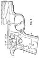
- FIG. 1 there is shown an elevation right side view of a firearm 10 incorporating features of the present invention.
- the present invention will be described with the reference to the single embodiment shown in the drawings, it should be understood that the present invention can be embodied in various different types and kinds of alternate embodiments and different types and kinds of firearms.
- any suitable size, shape or type of elements or materials could be used.
- the firearm 10 is a semi-automatic pistol.
- the pistol 10 has a receiver or frame 12, a barrel 14, a slide 15, a firing mechanism 16, and a removable cartridge magazine 18.
- a schematic cross-sectional view of the pistol 10 is shown without the cartridge magazine.
- the frame 12 is preferably a one-piece member made of metal. However, the frame could be a multi-piece assembly including other materials such as plastic.
- the frame 12 has a handgrip section 20 with a cartridge magazine receiving area 22, a trigger guard section 24 and a slot 26 for the trigger assembly 28.
- the barrel 14 has a bottom rear lug 30. Referring also to Figs.
- the lug 30 has a groove 32 and a rear bottom end 34 with a recess 36 on its right side.
- a lug pin or take down pin 38 is connected to the frame 12 and extends through the groove 32. Because of the shape of the groove 32, the barrel 14 can move on the lug pin 38.
- the slide 15 is slidingly mounted to the top of the frame 12. A main portion of the barrel 14 is located in a main channel of the slide 15. Tile rear of the slide has a firing pin 40 therein. When the slide 15 is moved rearward on the frame 12, the barrel 14 is moved rearward by the slide 15. As the barrel 14 is moved rearward, interaction between the lug pin 38 and the groove 32 causes the rear of the barrel to move downward.
- the recess 36 could be on the left side of the lug or in an interior area of the lug. Any suitable type of slide could also be provided. In addition, any suitable type of firing pin or striker could be provided.
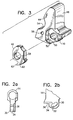
- the firing mechanism 16 includes the trigger assembly 28, the firing pin 40 and a hammer assembly 42.
- the hammer assembly 42 includes a first hammer member 44 and a second hammer member 46.
- the first hammer member 44 is made of metal, such as extruded, stamped or cast metal.
- the first hammer member 44 has a striking face 48, a mounting hole 50, a side pocket 52, a rear slot 54, and two rear holes 56 (only one of which is shown) on opposite sides of the rear slot 54.
- the second hammer member 46 is a plate made of metal.
- the plate 46 is preferably stamped from a hardened metal member.
- the plate 46 has a mounting hole 58 and a bottom projection 60 with a sear surface 62.
- the plate 46 is located in the side pocket 52 of the first member 44.
- the shapes of the pocket 52 and the portion of the plate 46 in the pocket interlock the two members together.
- the holes 50, 58 align with each other.
- a hammer pin 64 extends through the two holes 50, 58 to pivotably mount the hammer assembly 42 to the rear end of the frame 12.
- the projection 60 extends out of the pocket 52 and past the bottom end of the first hammer member 44.
- a strut pin 66 is mounted in the holes 56 and spans the rear slot 54.
- a hammer strut 68 extends into the slot 54.
- the strut 68 is spring loaded by a spring 70 against the strut pin 66. This biases the top of the hammer assembly 42 in a forward direction.
- hammer assemblies could be provided.
- alternative or additional means could be provided to interlock the two hammer members together. When assembled, the right sides of the two members 44, 46 are flush with each other. The interlocking nature of the two members allows the plate 46 to rotate the first member 44 when the plate 46 is rotated on the hammer pin 64. Likewise, when the first hammer member 44 rotates on the hammer pin 64, the first hammer member 44 causes the plate 46 to rotate with it.
- the trigger assembly 28 generally comprises a trigger member 72, a trigger spacer 74 and a trigger pull bar 76.
- the trigger member 72 is preferably a one piece member.
- the trigger member 72 has a bottom finger contact section 78, a middle section with a spacer pocket 80 and a mounting hole 82, and a top section 84 with a stop 86 and a side projection 88.
- the width of the finger contact section 78 is about the same width of the slot 26 in the frame 12.
- the spacer 74 is located in the pocket 80.
- the spacer 74 has a mounting hole 90.
- the hole 90 is aligned with the hole 82.
- a trigger pill 92 extends through the two holes 82, 90.
- the pin 92 is connected to the frame 12 across the slot 26. This pivotably mounts the trigger member 72 and spacer 74 to the frame 12. As seen best in Fig. 4, the combination of the trigger member 72 and the spacer 74 span the width W of the slot 26.
- the top section 84 is relatively thin and extends from only a right side of the trigger member 72.
- the width of the top section 84 at the side projection 88 is about the same as the width of the recess 36 in the barrel lug 30 (see Fig. 2a).
- the trigger bar 76 has a front end with a hole that is pivotably mounted on the side projection 88.
- the width of the front end of the trigger bar 76 is about the same width as the side projection 88.
- the stop 39 on the frame 12 stops the trigger member 72 from being rotated too much that might otherwise cause the lug 30 to contact the top section 84 of the trigger member 72. Therefore, a compact pistol can be provided which is also a double action only pistol, and has a pulled trigger bar.
- the contour of the recess 36 is such to minimize reduction in strength of the lug 30. The configuration described above also eliminates the need to make the pistol wider.
- the spacer 74 can be positioned in the pocket 80.
- the trigger pin 92 can then be used to pivotably mount the two members 72, 74 to the frame 12.
- a relatively long trigger member can be inserted into a trigger slot in a frame past a trigger guard.
- the two members 72, 74 occupy the width of the slot 26 such that the trigger member 72 does not significantly laterally slide on the pin 92.
- other types of trigger assemblies could be provided.
Abstract
Description
Claims (20)
- In a firearm having a frame, a barrel connected to the frame, and a firing mechanism connected to the frame, the firing mechanism having a hammer pivotably mounted to the frame, wherein the improvement comprises:the hammer having a first hammer member with a striking face and a second hammer member with a sear surface, the second hammer member comprising a plate that is stationarily interlocked with the first hammer member.
- A firearm as in Claim 1 wherein the first hammer member has a pocket and the second hammer member is located in the pocket to stationarily interlock the two member to each other.
- A firearm as in Claim 2 wherein the pocket is located on a lateral side of the first hammer member.
- A firearm as in claim 1 wherein the second hammer member is a flat plate made from sheet metal.
- A firearm as in Claim 4 wherein the first and second hammer members each have a hole with a pin extending through the holes to pivotably mount the two members to the frame.
- In a firearm having a frame, a barrel connected to the frame, and a firing mechanism connected to the frame, the frame including a frame member with a handgrip section and a panel connected to the handgrip section, wherein the improvement comprises:connection of the panel to the frame member including the panel having a projection at a first end of the panel with a first angled surface and a hole at a second end of the panel with a second angled surface, and the frame member having a slot with a third angled surface, wherein the projection extends into the slot with the first and third angled surfaces contacting each other and the connection has a single fastener that extends through the hole, is fastened to the frame member, and has a head that contacts the second angled surface to push the panel relative to the frame such that the first and third angled surface contact each other to securely seat the first end of the panel against the frame member.
- A firearm as in Claim 6 wherein the first end of the panel has two of the projections.
- A firearm as in Claim 7 wherein the frame member has two of the slots.
- A firearm as in Claim 6 wherein the fastener is the sole fastener used to connect the panel to the frame member.
- A firearm as in Claim 6 wherein the panel covers one side of the handgrip section, and a second panel is connected to an opposite side of the handgrip section with a similar connection.
- In a firearm having a frame, a barrel connected to the frame, and a firing mechanism connected to the frame, the barrel having a bottom rear lug movably connecting the barrel to the frame, the firing mechanism including a trigger pivotably mounted to the frame and a pull bar connected to the trigger, wherein the improvement comprises:the lug having a recess in its rear bottom end to allow a top of the trigger and a front of the pull bar to be moved under the barrel, the recess being contoured to substantially match a contour of the front of the pull bar and a front of the top of the trigger, and the trigger is pivotably mounted to the frame under the barrel.
- A firearm as in Claim 11 wherein a barrel mounting pin extends through a hole in the lug and a pivot pin that mounts the trigger to the frame is located partially under the barrel mounting pin.
- A firearm as in claim 11 wherein the pull bar has a sear surface on its rear end.
- A firearm as in Claim 11 wherein the trigger comprises a trigger member and a spacer, the trigger member having a reduced width at its pivotal mounting to the frame and the spacer being located in a slot of the frame next to the trigger member and being pivotably mounted to the frame with the trigger member by a single pivot pin.
- A firearm as in Claim 11 wherein the pull bar is pivotably connected to the top of the trigger and a spring directly connects a rear end of the pull bar to the frame.
- In a firearm having a frame, a barrel connected to the frame, and a firing mechanism connected to the frame, the frame having a trigger guard and a slot located above the trigger guard, the firing mechanism having a trigger extending through the slot and being pivotably mounted to the frame in the slot by a pivot pin, wherein the improvement comprises:the trigger comprising a trigger member and a spacer, the trigger member having a reduced width at the pivot pin that is less than a width of the slot such that the trigger member can be inserted through a bottom of the slot at an angle to pass the trigger guard, and the spacer is located next to the trigger member in the slot and connected to the frame by the pivot pin such that the trigger member and the spacer extend across the width of the slot to stably pivotably mount the trigger member on the pivot pin in the slot.
- A firearm as in Claim 16 wherein the firing mechanism includes a pull bar with a front end pivotably connected to a top of the trigger member and a rear end with a sear surface.
- A firearm as in Claim 16 wherein the barrel is movably mounted to the frame by a lug pin, the pivot pin is located partially under the lug pin when the barrel is in a horizontal position.
- A firearm as in Claim 18 wherein the barrel has a lug on its bottom rear that the lug pin extends through, and a rear end of the lug has a contoured shape that matches a contour of a top of the trigger and a front of a pull bar connected to the top of the trigger.
- A firearm as in Claim 16 wherein the firing mechanism has a hammer with a first member having a striking face and a second member having a sear surface, the second member being stationarily interlocked with the first member.
Applications Claiming Priority (2)
| Application Number | Priority Date | Filing Date | Title |
|---|---|---|---|
| US08/745,045 US5815973A (en) | 1996-11-07 | 1996-11-07 | Compact pistol |
| US745045 | 1996-11-07 |
Publications (2)
| Publication Number | Publication Date |
|---|---|
| EP0841528A2 true EP0841528A2 (en) | 1998-05-13 |
| EP0841528A3 EP0841528A3 (en) | 1999-09-01 |
Family
ID=24995025
Family Applications (1)
| Application Number | Title | Priority Date | Filing Date |
|---|---|---|---|
| EP97119497A Withdrawn EP0841528A3 (en) | 1996-11-07 | 1997-11-07 | Double action firing mechanism with a hammer for a pistol |
Country Status (4)
| Country | Link |
|---|---|
| US (2) | US5815973A (en) |
| EP (1) | EP0841528A3 (en) |
| BR (1) | BR9705439A (en) |
| CA (1) | CA2220499A1 (en) |
Families Citing this family (24)
| Publication number | Priority date | Publication date | Assignee | Title |
|---|---|---|---|---|
| US5815973A (en) * | 1996-11-07 | 1998-10-06 | Colt's Manufacturing Company, Inc. | Compact pistol |
| US6283006B1 (en) * | 1998-08-24 | 2001-09-04 | Angelotti Inc. | Double action pistol |
| US6415702B1 (en) * | 1998-11-23 | 2002-07-09 | Angelotti, Inc. | Double action semi-automatic handgun |
| US6253479B1 (en) * | 1999-06-04 | 2001-07-03 | Sig Arms International Ag | Pistol having a safety for preventing accidental firing |
| US6519887B1 (en) * | 2000-12-21 | 2003-02-18 | Smith & Wesson Corp. | Magazine safety |
| US6865979B1 (en) * | 2001-02-07 | 2005-03-15 | Smith & Wesson Corp. | Apparatus and method for removing the slide of a semi-automatic pistol |
| MXPA05003697A (en) * | 2002-10-07 | 2005-06-17 | J Moore Wildey | Frame construction for with removable side plate. |
| US7322143B2 (en) * | 2003-02-14 | 2008-01-29 | Rohrbaugh Firearms Corp. | Semiautomatic handgun |
| US7698845B2 (en) * | 2004-12-16 | 2010-04-20 | New Colt Holding Corporation | Double action model 1911 pistol |
| US7472507B2 (en) | 2004-12-22 | 2009-01-06 | Smith & Wesson Corp. | Firearm with modular sear and trigger mechanism housings |
| US7617628B2 (en) | 2004-12-22 | 2009-11-17 | Smith & Wesson Corp. | Fire control mechanism for a firearm |
| US7389719B2 (en) | 2004-12-22 | 2008-06-24 | Smith & Wesson Corp. | Wire bushing for use with a firearm barrel |
| US7703230B2 (en) | 2004-12-22 | 2010-04-27 | Smith & Wesson Corp. | Positive striker lock safety for use with a firearm |
| US7600340B2 (en) | 2004-12-22 | 2009-10-13 | Smith & Wesson Corp. | Locking apparatus for a firearm |
| US7380362B2 (en) | 2004-12-22 | 2008-06-03 | Smith & Wesson Corp. | Firearm extractor mechanism |
| US7392611B2 (en) | 2004-12-22 | 2008-07-01 | Smith & Wesson Corp. | Apparatus and method for firearm takedown |
| US7506469B2 (en) | 2004-12-22 | 2009-03-24 | Smith & Wesson Corp. | Firearm frame with configurable grip |
| US20060169268A1 (en) * | 2005-02-01 | 2006-08-03 | Tippmann Dennis J Jr | Receiver/grip assembly for a paintball marker |
| US8132496B2 (en) | 2008-12-30 | 2012-03-13 | Smith & Wesson Corp. | Automatic firing pin block safety for a firearm |
| US9057574B2 (en) | 2012-06-14 | 2015-06-16 | Ra Brands, L.L.C. | Thumb safety for model 1911 handgun |
| US9551545B1 (en) * | 2013-05-07 | 2017-01-24 | Jeffrey J. Rowe | Pivot axis pin fixtures for rifle receivers |
| US11009303B2 (en) * | 2014-06-17 | 2021-05-18 | Daniel Defense, Llc | Firearm barrel assembly |
| EP3397917B1 (en) * | 2015-12-28 | 2021-05-19 | Sturm, Ruger & Company, Inc. | Varying barrel camming system for firearm |
| USD853517S1 (en) | 2016-10-21 | 2019-07-09 | Taurus International Manufacturing, Inc. | Firearm with magazine |
Citations (7)
| Publication number | Priority date | Publication date | Assignee | Title |
|---|---|---|---|---|
| US3672084A (en) | 1970-06-08 | 1972-06-27 | Mershon Co | Reinforced pistol grip |
| US3682040A (en) | 1969-10-08 | 1972-08-08 | Colt S Inc | En bloc fire control group for a pistol |
| US4021955A (en) | 1976-05-03 | 1977-05-10 | Colt Industries Operating Corporation (Firearms Division) | Firing pin locking device and method |
| US4132024A (en) | 1977-10-03 | 1979-01-02 | Packmayr Gun Works, Inc. | Cushioned pistol grip |
| US4306487A (en) | 1978-02-24 | 1981-12-22 | Fabbrica D'armi Pietro Beretta S.P.A. | Safety device for a pistol |
| US4555861A (en) | 1983-12-16 | 1985-12-03 | Colt Industries Operating Corp | Firing pin locking device |
| US5050480A (en) | 1989-12-08 | 1991-09-24 | Kniarmco Inc. | Trigger assembly for a firearm |
Family Cites Families (46)
| Publication number | Priority date | Publication date | Assignee | Title |
|---|---|---|---|---|
| US456166A (en) * | 1891-07-21 | Gun-lock | ||
| US57978A (en) * | 1866-09-11 | Improvement in gun-locks | ||
| US27868A (en) * | 1860-04-10 | Improvement in revolving fire-arms | ||
| US7547A (en) * | 1850-08-06 | Improved method of making barrels for fire-arms | ||
| US808214A (en) * | 1905-06-19 | 1905-12-26 | Harry M Putnam | Firearm. |
| US1004424A (en) * | 1909-11-04 | 1911-09-26 | Daniel G Hennick | Automatic firearm. |
| US1228506A (en) * | 1916-12-29 | 1917-06-05 | Smith & Wesson | Pistol-stock. |
| US1381590A (en) * | 1917-09-13 | 1921-06-14 | Oliver Stacy | Automatic pistol |
| GB150864A (en) * | 1919-07-04 | 1920-09-16 | Westley Richards & Co Ltd | Improvements in or relating to the locks of breech loading fire arms |
| BE410932A (en) * | 1934-08-10 | |||
| US2530363A (en) * | 1947-05-09 | 1950-11-14 | Carl G Swebilius | Action slide for firearms |
| US2464427A (en) * | 1948-01-02 | 1949-03-15 | High Standard Mfg Corp | Double-action mechanism for pistols |
| US2600176A (en) * | 1949-12-13 | 1952-06-10 | Olin Ind Inc | Unitary hammer spring and trigger spring for firearms |
| US2722074A (en) * | 1950-05-16 | 1955-11-01 | Jr Theodore M Bray | Hammer action for firearms |
| DE910625C (en) * | 1951-07-17 | 1954-05-03 | Dr Josef Buerke | Drum revolver |
| US3051057A (en) * | 1960-08-18 | 1962-08-28 | Jessie T Ivy | Automatic hammer cocking and cylinder indexing means for revolvers |
| US3152418A (en) * | 1962-03-09 | 1964-10-13 | Smith And Wesson Inc | Single or double action firearm |
| US3337979A (en) * | 1965-03-04 | 1967-08-29 | George H Freed | Firing mechanism for firearms |
| US3269045A (en) * | 1965-03-11 | 1966-08-30 | Robert E Mcgaughey | Revolver with shooting trigger and digitally engageable auxiliary means secured thereto |
| US3531886A (en) * | 1968-05-29 | 1970-10-06 | Olin Mathieson | Firearm hammer |
| US3577667A (en) * | 1968-10-29 | 1971-05-04 | Robert P Kern | Lock for percussion cap rifle |
| US3701213A (en) * | 1969-03-18 | 1972-10-31 | Colt Ind Operating Corp | Revolver firing mechanism with single action and double action movement |
| US3768190A (en) * | 1972-01-03 | 1973-10-30 | Sturm Ruger & Co | Loading gate arrangement for single action revolver |
| US3815270A (en) * | 1973-05-29 | 1974-06-11 | Pachmayr Gun Works | Resilient pistol grip |
| US4126953A (en) * | 1977-01-14 | 1978-11-28 | Casull Richard J | Single action revolver with safety locking cylinder |
| BE876396R (en) * | 1979-01-10 | 1979-11-21 | Herstal Sa | PERFECTED GUN |
| US4285152A (en) * | 1979-03-23 | 1981-08-25 | Dean Joe O | Semi-automatic double action revolver |
| US4276709A (en) * | 1979-11-14 | 1981-07-07 | Robert Bross | Handgun stock pommel |
| DE3235918T1 (en) * | 1981-03-10 | 1984-09-20 | Saxhoej, Thorben, Rungsted Kyst | DEDUCTION AND COMBINED LOCKING AND SECURING FOR A WEAPON |
| US4472901A (en) * | 1981-11-27 | 1984-09-25 | Hillberg Robert L | Pistol grip assembly |
| CS236304B1 (en) * | 1983-09-30 | 1985-05-15 | Vaclav Polansky | Breech mechanism capture for automatic fire arms especially for pistols |
| US4586282A (en) * | 1983-10-03 | 1986-05-06 | Bangor Punta Corporation | Grip assembly for a handgun |
| US4577430A (en) * | 1984-06-25 | 1986-03-25 | Sturm, Ruger & Company, Inc. | Trigger and spring mount mechanism |
| US4575963A (en) * | 1984-06-25 | 1986-03-18 | Sturm, Ruger & Company, Inc. | Pistol mechanism for blocking firing pin |
| US4771562A (en) * | 1985-03-28 | 1988-09-20 | Sturm, Ruger & Company, Inc. | Grips for handguns |
| IT1215841B (en) * | 1988-02-10 | 1990-02-22 | Emilio Ghisoni | LOWERED BARREL REVOLVER. |
| BR8805801A (en) * | 1988-11-03 | 1990-06-19 | Forjas Taurus Sa | MANUFACTURING PROCESS FOR SEMI-AUTOMATIC PISTOLS WITH MONOBLOCK STRUCTURE AND RESULTING PRODUCT |
| US5166458A (en) * | 1991-01-11 | 1992-11-24 | Daewoo Precision Ind., Ltd. | Firing mechanism for fast shooting pistol |
| US5050329A (en) * | 1991-03-04 | 1991-09-24 | Hogue Grips | Two-piece handgrip for hand gun |
| IL100548A0 (en) * | 1991-12-30 | 1992-09-06 | Israel Military Ind | Double action pistol with improved firing mechanism |
| DE4220922C2 (en) * | 1992-06-25 | 1996-03-21 | Heckler & Koch Gmbh | Hand gun with interchangeable functional element |
| US5426880A (en) * | 1993-10-07 | 1995-06-27 | Sturm, Ruger & Company, Inc. | Elongated element for biasing the trigger bar and controlling the slide stop latch in an automatic pistol |
| US5359799A (en) * | 1993-06-25 | 1994-11-01 | Moon Kook Jin | Firearm trigger bar attachment |
| US5415075A (en) * | 1993-09-17 | 1995-05-16 | Moon; Kook-Jin | Staggered camming machanism for a firearm |
| DE19507052A1 (en) * | 1995-03-01 | 1996-09-05 | Walther Carl Gmbh | Firearm trigger |
| US5815973A (en) * | 1996-11-07 | 1998-10-06 | Colt's Manufacturing Company, Inc. | Compact pistol |
-
1996
- 1996-11-07 US US08/745,045 patent/US5815973A/en not_active Expired - Lifetime
-
1997
- 1997-11-06 BR BR9705439A patent/BR9705439A/en not_active Application Discontinuation
- 1997-11-07 CA CA002220499A patent/CA2220499A1/en not_active Abandoned
- 1997-11-07 EP EP97119497A patent/EP0841528A3/en not_active Withdrawn
-
1998
- 1998-10-05 US US09/166,258 patent/US6000162A/en not_active Expired - Lifetime
Patent Citations (7)
| Publication number | Priority date | Publication date | Assignee | Title |
|---|---|---|---|---|
| US3682040A (en) | 1969-10-08 | 1972-08-08 | Colt S Inc | En bloc fire control group for a pistol |
| US3672084A (en) | 1970-06-08 | 1972-06-27 | Mershon Co | Reinforced pistol grip |
| US4021955A (en) | 1976-05-03 | 1977-05-10 | Colt Industries Operating Corporation (Firearms Division) | Firing pin locking device and method |
| US4132024A (en) | 1977-10-03 | 1979-01-02 | Packmayr Gun Works, Inc. | Cushioned pistol grip |
| US4306487A (en) | 1978-02-24 | 1981-12-22 | Fabbrica D'armi Pietro Beretta S.P.A. | Safety device for a pistol |
| US4555861A (en) | 1983-12-16 | 1985-12-03 | Colt Industries Operating Corp | Firing pin locking device |
| US5050480A (en) | 1989-12-08 | 1991-09-24 | Kniarmco Inc. | Trigger assembly for a firearm |
Also Published As
| Publication number | Publication date |
|---|---|
| EP0841528A3 (en) | 1999-09-01 |
| BR9705439A (en) | 1999-05-04 |
| US6000162A (en) | 1999-12-14 |
| US5815973A (en) | 1998-10-06 |
| CA2220499A1 (en) | 1998-05-07 |
Similar Documents
| Publication | Publication Date | Title |
|---|---|---|
| US5815973A (en) | Compact pistol | |
| US7698845B2 (en) | Double action model 1911 pistol | |
| US8037805B1 (en) | Pistol with off-axis slide | |
| US8127481B2 (en) | Model 1911 semiautomatic pistol thumb safety | |
| US4522105A (en) | Firing mechanism for semiautomatic firearms | |
| US4056038A (en) | Dual purpose semi-automatic convertible rifle | |
| US4562659A (en) | Automatic firearm | |
| US3688641A (en) | Machine gun | |
| US20010042334A1 (en) | Grenade launcher | |
| US10514223B1 (en) | Firearm trigger mechanism | |
| US4409882A (en) | Hand gun | |
| US4358987A (en) | Semiautomatic hand gun having an elongated take down pin | |
| US5821445A (en) | Loading lever assembly for hand-operated firearms | |
| US3791256A (en) | Machine gun | |
| US20230003482A1 (en) | Bolt catch for a firearm | |
| US6266909B1 (en) | Pistol having a safety for preventing firing during disassembly | |
| US5320023A (en) | Semiautomatic pistol | |
| US5483766A (en) | Combined handgrip and trigger guard for a firearm | |
| US5691497A (en) | Self-loading grenade launcher | |
| US4619184A (en) | Gas actuated pistol | |
| US4536981A (en) | Firearm assembly | |
| US4361975A (en) | Semiautomatic hand gun | |
| US4481863A (en) | Operating lever for the block and hammer of a self-loading hand firearm | |
| US7047684B2 (en) | Short repeater rifle | |
| EP0719403B1 (en) | Firearm having staggered camming mechanism |
Legal Events
| Date | Code | Title | Description |
|---|---|---|---|
| PUAI | Public reference made under article 153(3) epc to a published international application that has entered the european phase |
Free format text: ORIGINAL CODE: 0009012 |
|
| AK | Designated contracting states |
Kind code of ref document: A2 Designated state(s): AT BE CH DE IT LI |
|
| AX | Request for extension of the european patent |
Free format text: AL;LT;LV;MK;RO;SI |
|
| RIC1 | Information provided on ipc code assigned before grant |
Free format text: 6F 41A 19/48 A, 6F 41A 19/14 B |
|
| PUAL | Search report despatched |
Free format text: ORIGINAL CODE: 0009013 |
|
| AK | Designated contracting states |
Kind code of ref document: A3 Designated state(s): AT BE CH DE DK ES FI FR GB GR IE IT LI LU MC NL PT SE |
|
| AX | Request for extension of the european patent |
Free format text: AL;LT;LV;MK;RO;SI |
|
| AKX | Designation fees paid |
Free format text: AT BE CH DE IT LI |
|
| STAA | Information on the status of an ep patent application or granted ep patent |
Free format text: STATUS: THE APPLICATION IS DEEMED TO BE WITHDRAWN |
|
| 18D | Application deemed to be withdrawn |
Effective date: 20000302 |