EP0840153A2 - Optical waveguide module having waveguide substrate made of predetermined material and ferrule made of material different from that of waveguide substrate - Google Patents
Optical waveguide module having waveguide substrate made of predetermined material and ferrule made of material different from that of waveguide substrate Download PDFInfo
- Publication number
- EP0840153A2 EP0840153A2 EP98101067A EP98101067A EP0840153A2 EP 0840153 A2 EP0840153 A2 EP 0840153A2 EP 98101067 A EP98101067 A EP 98101067A EP 98101067 A EP98101067 A EP 98101067A EP 0840153 A2 EP0840153 A2 EP 0840153A2
- Authority
- EP
- European Patent Office
- Prior art keywords
- ferrule
- waveguide
- optical
- optical waveguide
- thermal expansion
- Prior art date
- Legal status (The legal status is an assumption and is not a legal conclusion. Google has not performed a legal analysis and makes no representation as to the accuracy of the status listed.)
- Withdrawn
Links
Images


Classifications
-
- G—PHYSICS
- G02—OPTICS
- G02B—OPTICAL ELEMENTS, SYSTEMS OR APPARATUS
- G02B6/00—Light guides; Structural details of arrangements comprising light guides and other optical elements, e.g. couplings
- G02B6/24—Coupling light guides
- G02B6/36—Mechanical coupling means
- G02B6/38—Mechanical coupling means having fibre to fibre mating means
- G02B6/3807—Dismountable connectors, i.e. comprising plugs
- G02B6/3833—Details of mounting fibres in ferrules; Assembly methods; Manufacture
- G02B6/3834—Means for centering or aligning the light guide within the ferrule
- G02B6/3838—Means for centering or aligning the light guide within the ferrule using grooves for light guides
- G02B6/3839—Means for centering or aligning the light guide within the ferrule using grooves for light guides for a plurality of light guides
-
- G—PHYSICS
- G02—OPTICS
- G02B—OPTICAL ELEMENTS, SYSTEMS OR APPARATUS
- G02B6/00—Light guides; Structural details of arrangements comprising light guides and other optical elements, e.g. couplings
- G02B6/24—Coupling light guides
- G02B6/26—Optical coupling means
- G02B6/30—Optical coupling means for use between fibre and thin-film device
-
- G—PHYSICS
- G02—OPTICS
- G02B—OPTICAL ELEMENTS, SYSTEMS OR APPARATUS
- G02B6/00—Light guides; Structural details of arrangements comprising light guides and other optical elements, e.g. couplings
- G02B6/24—Coupling light guides
- G02B6/36—Mechanical coupling means
- G02B6/38—Mechanical coupling means having fibre to fibre mating means
- G02B6/3807—Dismountable connectors, i.e. comprising plugs
- G02B6/3833—Details of mounting fibres in ferrules; Assembly methods; Manufacture
- G02B6/3834—Means for centering or aligning the light guide within the ferrule
-
- G—PHYSICS
- G02—OPTICS
- G02B—OPTICAL ELEMENTS, SYSTEMS OR APPARATUS
- G02B6/00—Light guides; Structural details of arrangements comprising light guides and other optical elements, e.g. couplings
- G02B6/24—Coupling light guides
- G02B6/36—Mechanical coupling means
- G02B6/38—Mechanical coupling means having fibre to fibre mating means
- G02B6/3807—Dismountable connectors, i.e. comprising plugs
- G02B6/3873—Connectors using guide surfaces for aligning ferrule ends, e.g. tubes, sleeves, V-grooves, rods, pins, balls
- G02B6/3885—Multicore or multichannel optical connectors, i.e. one single ferrule containing more than one fibre, e.g. ribbon type
-
- G—PHYSICS
- G02—OPTICS
- G02B—OPTICAL ELEMENTS, SYSTEMS OR APPARATUS
- G02B6/00—Light guides; Structural details of arrangements comprising light guides and other optical elements, e.g. couplings
- G02B6/24—Coupling light guides
- G02B6/36—Mechanical coupling means
- G02B6/38—Mechanical coupling means having fibre to fibre mating means
- G02B6/3807—Dismountable connectors, i.e. comprising plugs
- G02B6/3833—Details of mounting fibres in ferrules; Assembly methods; Manufacture
- G02B6/3834—Means for centering or aligning the light guide within the ferrule
- G02B6/3835—Means for centering or aligning the light guide within the ferrule using discs, bushings or the like
- G02B6/3837—Means for centering or aligning the light guide within the ferrule using discs, bushings or the like forwarding or threading methods of light guides into apertures of ferrule centering means
-
- G—PHYSICS
- G02—OPTICS
- G02B—OPTICAL ELEMENTS, SYSTEMS OR APPARATUS
- G02B6/00—Light guides; Structural details of arrangements comprising light guides and other optical elements, e.g. couplings
- G02B6/24—Coupling light guides
- G02B6/36—Mechanical coupling means
- G02B6/38—Mechanical coupling means having fibre to fibre mating means
- G02B6/3807—Dismountable connectors, i.e. comprising plugs
- G02B6/3833—Details of mounting fibres in ferrules; Assembly methods; Manufacture
- G02B6/3855—Details of mounting fibres in ferrules; Assembly methods; Manufacture characterised by the method of anchoring or fixing the fibre within the ferrule
- G02B6/3861—Adhesive bonding
-
- G—PHYSICS
- G02—OPTICS
- G02B—OPTICAL ELEMENTS, SYSTEMS OR APPARATUS
- G02B6/00—Light guides; Structural details of arrangements comprising light guides and other optical elements, e.g. couplings
- G02B6/24—Coupling light guides
- G02B6/36—Mechanical coupling means
- G02B6/38—Mechanical coupling means having fibre to fibre mating means
- G02B6/3807—Dismountable connectors, i.e. comprising plugs
- G02B6/3833—Details of mounting fibres in ferrules; Assembly methods; Manufacture
- G02B6/3863—Details of mounting fibres in ferrules; Assembly methods; Manufacture fabricated by using polishing techniques
-
- G—PHYSICS
- G02—OPTICS
- G02B—OPTICAL ELEMENTS, SYSTEMS OR APPARATUS
- G02B6/00—Light guides; Structural details of arrangements comprising light guides and other optical elements, e.g. couplings
- G02B6/24—Coupling light guides
- G02B6/42—Coupling light guides with opto-electronic elements
- G02B6/4201—Packages, e.g. shape, construction, internal or external details
- G02B6/4219—Mechanical fixtures for holding or positioning the elements relative to each other in the couplings; Alignment methods for the elements, e.g. measuring or observing methods especially used therefor
- G02B6/4236—Fixing or mounting methods of the aligned elements
- G02B6/4239—Adhesive bonding; Encapsulation with polymer material
Definitions
- the present invention relates to an optical waveguide module comprising at least a ferrule for holding one end of an optical fiber and a waveguide component having an optical waveguide on a substrate made of a material different from that of the ferrule and serving as an optical component and, more particularly, to a ferrule capable of obtaining good temperature characteristics and good moist heat characteristics in terms of a relationship with the material of the substrate, an optical waveguide module utilizing this ferrule and the optical component, and a method of manufacturing this optical waveguide module.
- a planar optical waveguide has a low waveguide loss (a transmission loss accompanying optical branching and the like) and enables low-loss connection with an optical fiber.
- Japanese Patent Laid-Open No. 58-105111 discloses a buried type silica-based waveguide component obtained by a scheme of forming a glass film in accordance with, e.g., flame hydrolysis (FHD), thereafter forming a circuit pattern in accordance with reactive ion etching (RIE) which is an application of a semiconductor technique, and forming a film of a cladding portion.
- FHD flame hydrolysis
- RIE reactive ion etching
- a waveguide component When such a waveguide component is to be utilized in an optical component (e.g., an optical waveguide module), input/output optical fibers are generally connected to an optical waveguide formed in this waveguide component.
- a silica-based ferrule which is precision-machined and in which optical fibers are fixed is used, as indicated in, e.g., IEEE Photonic Technology Letters, vol. 4, No. 8, (1992), pp. 906 - 908.
- the end face of the silica-based ferrule is fixed by adhesion to the end face of the waveguide component by using an ultraviolet-curing adhesive.
- Japanese Patent Laid-Open No. 6-51155 discloses a technique for forming a ferrule with silica glass which transmits ultraviolet rays therethrough and solidifying an adhesive between the end faces of the ferrule and waveguide component with each other uniformly within a short period of time, thereby shortening the work time and decreasing the possibility of misalignment between the end faces of the ferrule and waveguide component.
- an optical waveguide formed in the waveguide component has a diameter (core diameter) of 10 ⁇ m or less.
- a ferrule for holding the end portions of optical fibers is generally made of silica glass having a thermal expansion coefficient almost equal to that of the material of the waveguide substrate, as described above, so that desired temperature characteristics and moist heat characteristics can be obtained.
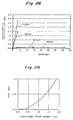
- 29 is a graph showing the relationship, in a single-mode optical waveguide having a mode field diameter of 10 ⁇ m, between the positional shift amount between the end faces of the optical waveguides and the end faces of the cores of the optical fibers and the transmission loss of the optical waveguide.
- the ferrule when an optical waveguide module is to be manufactured with silica glass described above, a material, e.g., glass, which is difficult to machine must be machined at high precision within 1 ⁇ m, as disclosed in the above official gazettes (machining of grooves for fixing the positions of optical fibers). Furthermore, the ferrule must be constituted by a plurality of constituent members (the end portions of the optical fibers must be sandwiched by upper and lower silica glass plates) to clamp the end portions of the optical fibers.
- a ferrule When a ferrule is to be formed of a plastic material, it can be molded with a single step by plastic molding, and through holes (having continuous inner walls) that define the positions of the optical fibers upon insertion of the end portions of the optical fibers can also be formed at high precision during this plastic molding, as described in, e.g., "DEVELOPMENT OF 16-FIBER CONNECTORS FOR HIGH-SPEED LOW-LOSS CABLE CONNECTION" (INTERNATIONAL WIRE AND CABLE SYMPOSIUM PROCEEDINGS 1993, pp. 244 - 249).
- the end portions of the optical fibers need not be clamped by preparing a plurality of members for the purpose of obtaining the clamping structure of the end portions of the optical fibers (since through holes that define the positions of the end portions of the optical fibers can be formed simultaneously during plastic molding, the positioned distal ends of the optical fibers need not be vertically sandwiched and clamped). Also, no high-precision machining technique is required (since the through holes are formed in units of the optical fibers at high precision, precision machining, e.g., formation of grooves for fixing the positions of optical fibers in the clamping members, is not needed). Therefore, this plastic material is suitable as the material of the ferrule.
- the present invention has been made in view of the above situations, and has as its object to provide an optical waveguide module which utilizes a ferrule made of a low-cost plastic material that can be continuously molded and high-precision machined easily, in place of a material, e.g., glass, which is difficult to machine, comprises a waveguide component (in particular, a waveguide substrate) and a ferrule made of materials having different thermal expansion coefficients, and which has stable temperature characteristics and moist heat characteristics even in a severe environment; and a method of manufacturing the same.
- An optical waveguide module of the present invention comprises a waveguide component obtained by forming an optical waveguide constituting at least part of a transmission line for propagating light having a predetermined wavelength on a waveguide substrate made of the first material (e.g., silicon or silica glass is suitable as the first material), and a ferrule made of the second material (e.g., a plastic material is suitable as the second material) and fixed with an adhesive having a predetermined strength such that an end face thereof opposes the end face of the waveguide component while holding one end of an optical fiber (the end portion of the optical fiber is placed as it is inserted in a through hole having a continuous inner wall), so as to optically couple the optical fiber constituting at least part of the transmission line and the optical waveguide of the waveguide component.
- the first material e.g., silicon or silica glass is suitable as the first material
- a ferrule made of the second material e.g., a plastic material is suitable as the second material
- This optical waveguide module further comprises an input/output optical fiber fixed by adhesion in the ferrule such that its end portion is inserted in the through hole of the ferrule.
- the optical fiber is constituted by a core for propagating light having a predetermined wavelength, and a cladding layer covering the core. Normally, the optical fiber is utilized while the surface of the cladding layer is covered with a polyacrylate-based resin. The surface of the resin coating may be further covered with a plastic.
- the optical fiber is not limited to a single-fiber fiber but includes a ribbon fiber (for example, a 8-fiber ribbon fiber as shown in Figs. 7 and 8) obtained by integrally covering a plurality of optical fibers (each optical fiber may be coated with a polyacrylate-based resin colored in different colors) with a plastic material.
- the first material to form the substrate portion of the waveguide component and the second material to form the ferrule satisfy a relation:
- ⁇ L is a difference in thermal expansion coefficient between the first material and the second material
- E 1 is the modulus of elasticity of the first material
- E 2 is the modulus of elasticity of the second material.
- the plastic material to form the ferrule is a phenol-based epoxy resin containing a predetermined amount of silica filler
- its thermal expansion coefficient is 10 x 10 -6 (°C -1 ) or less.
- this thermal expansion coefficient is preferably 6 x 10 -6 (°C -1 ) or less.
- the content of the silica filler contained in this phenol-based epoxy resin is 85 weight % or more and 95 weight % or less. In order to obtain further superior moist heat characteristics, this content is preferably 90 weight % or more and 95 weight % or less. At this time, the modulus of elasticity of the above phenol-based epoxy resin is 5,000 (kg/mm 2 ) or less.
- an ultraviolet-curing adhesive or thermosetting adhesive having an adhesion strength of 50 (kg/cm 2 ) or more with respect to silica glass is employed. Furthermore, an adhesive having both ultraviolet-curing and thermosetting properties can be used.
- a waveguide component in which an optical waveguide constituting at least part of a transmission line for propagating light having a predetermined wavelength is formed on a waveguide substrate made of the first material, and a ferrule made of the second material and fixed with an adhesive to the end portion of an optical fiber (including input/output optical fibers) constituting at least part of the transmission line, while the end portion of the optical fiber is inserted in a through hole having a continuous inner wall are prepared.
- of the second material e.g., a plastic material is suitable
- the first material e.g., silicon or silica glass is suitable
- the end face of the waveguide component and the end face of the ferrule are abutted with each other and are adhered to each other with an adhesive, e.g., an ultraviolet-curing or thermoset adhesive having an adhesion strength of 50 (kg/cm 2 ) or more with respect to silica glass.
- an adhesive e.g., an ultraviolet-curing or thermoset adhesive having an adhesion strength of 50 (kg/cm 2 ) or more with respect to silica glass.
- the ferrule according to the present invention is made of a phenol-based epoxy resin containing a predetermined amount of silica filler and having a thermal expansion coefficient of 10 x 10 -6 (°C -1 ) or less, preferably 6 x 10 -6 (°C -1 ) or less.
- the content of the silica filler is 85 weight % or more and 95 weight % or less, and preferably 90 weight % or more and 95 weight % or less.
- the plastic material to form this ferrule is preferably a phenol-based epoxy resin having a modulus of elasticity of 5,000 (kg/mm 2 ) or less.
- this optical waveguide module is constituted by utilizing the respective constituent members made of different materials, e.g., a waveguide substrate made of silicon or silica glass and a ferrule made of a plastic material, if the effective thermal expansion coefficient of the material forming the ferrule with respect to the material forming the waveguide substrate is set to 3 x 10 -6 (°C -1 ) or less, as indicated by the above equation (1), the shift amount between the end faces of the cores which is caused by temperature variations can be suppressed to 1 ⁇ m or less, that is, the coupling loss can be suppressed to 0.3 dB or less.
- the present inventors confirmed that, in order to obtain a ferrule that can be applied to a silica glass substrate constituting part of the waveguide component (in order to satisfy the above conditions), the ferrule had to be made of a plastic material (having a thermal expansion coefficient of 3 x 10 -6 °C -1 or more and 10 x 10 -6 °C -1 or less) containing at least 75 weight % of a silica filler, and that in order to obtain a ferrule that can be applied to a silicon substrate, the ferrule must be made of a plastic material (having a thermal expansion coefficient of 3 x 10 -6 °C -1 or more and 10 x 10 -6 °C -1 or less) containing at least 85 weight % of a silica filler. It was also confirmed that at this time the optical waveguide module having the above arrangement could obtain good temperature characteristics.
- the lower limit of the thermal expansion coefficient of the plastic material as the material to form the ferrule is 3 x 10 -6 (°C -1 ) (see Fig. 19).
- the 96 volume % as the silica filler content can be roughly regard as the 96 weight % as the silica filler content.
- an optical waveguide module having both good temperature characteristics and good moist heat characteristics can be obtained.
- an optical waveguide module can be obtained which satisfies the temperature characteristic specifications of a component used indoors described above (10 cycles (48 hours) with temperature variations from -10°C to 60°C), and the temperature characteristic specifications of TR-NWT-001209 manufactured by Bellcore (42 cycles (336 hours) with temperature variations from -40°C to 75°C).
- an optical waveguide module which reliably satisfies the moist heat characteristics (60°C, 95 RH, 336 hours) of TR-NWT-001209 manufactured by Bellcore can be obtained.
- Fig. 1 is a view for explaining the assembling process of an optical waveguide module according to the present invention
- Fig. 2 is a perspective view showing the entire arrangement of the optical waveguide module according to the present invention.
- a ferrule 3 to which the end portion of an input/output ribbon fiber 4 is fixed by adhesion with an adhesive 5 as exposed optical fibers of the ribbon fiber 4 are inserted in through holes, and a waveguide component 1 having, on a waveguide substrate, optical waveguides (cores) for propagating light having a predetermined wavelength are prepared.
- a reinforcing member 2 is prepared to obtain a sufficiently high adhesion strength between the ferrule 3 and the waveguide component 1.
- the reinforcing member 2 has a bottom surface 2b fixed by adhesion on an upper surface 1b of the waveguide component 1 with an adhesive and a side surface 2a opposing an adhering end face 3c of the ferrule 3.
- An adhering end face 1a of the waveguide component 1 having the upper surface 1b to which the reinforcing member 2 has already been fixed by adhesion and the adhering end face 3c of the ferrule 3 that holds the end portions of the expose optical fibers of the ribbon fiber 4 are optically polished by sequentially performing the following steps.
- the adhering surface (side surface) 2a of the reinforcing member 2 is polished simultaneously during polishing the end face of the waveguide component 1, and the end faces of the cores of the optical fibers fixed by the ferrule 3 are also polished simultaneously during polishing the end face of the ferrule 3.
- the angle of each end face may be shifted with respect to the propagation direction (this direction coincides with a direction to insert the ribbon fiber 4 into the ferrule 3) at an adhering or connecting portion 13 from 90° in accordance with the necessity of decrease or the like of the amount of optical attenuation which is caused by reflection of the end face. Angle adjustment required in this case is performed in the first step.
- a polishing method other than the above polishing method is also known. Thus, a polishing method will be selected as required.
- the input/output end face 1a of the waveguide component 1 and the adhering end face 3c of the ferrule 3 are abutted against each other and adhered to each other with an adhesive 6.
- the end faces of the optical waveguides formed in the waveguide component 1 and the end faces of the cores of the optical fibers of the ribbon fiber 4 are aligned.
- the optical fibers have already been fixed in the ferrule 3 with the adhesive 5 having a predetermined strength, while being inserted in through holes of the ferrule 3.
- the bottom surface 2b of the reinforcing member 2 and the upper surface 1b of the waveguide component 1; and the adhering surface 2a of the reinforcing member 2, the adhering surface 2a of the reinforcing member 2, and the adhering face 1a of the waveguide component 1 are adhered to each other with an ultraviolet-curing or thermosetting adhesive having an adhesion strength of 50 kg/cm 2 or more, and preferably 100 kg/cm 2 or more, with respect to silica glass. Furthermore, an adhesive having both ultraviolet-curing and thermosetting properties can be used if it has an enough adhesion strength such as 50 kg/cm 2 or more with respect to silica glass.
- the adhering portion 13 is irradiated with ultraviolet rays or is heated to a predetermined temperature, thereby solidifying the adhesive.
- This series of operations adheresion of the respective end faces at the adhering portion 13 - alignment - solidification of the adhesive) are performed for each of the two input/output end faces of the waveguide component 1, thereby obtaining an optical waveguide module as shown in Fig. 2 according to the first embodiment of the present invention.
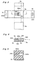
- Fig. 3 is a developed view showing the structure of this ferrule 3.
- reference symbol 3a denotes the upper surface of the ferrule 3; 3b, the side surface thereof; 3c, the front surface (adhering surface) thereof; 3d, the bottom surface thereof; and 3e, the rear surface (in which the distal end of the ribbon fibers 4 is inserted) thereof.
- a window 310 is formed in advance in the upper surface 3a of the ferrule 3 in order to observe insertion of the distal end (a plurality of optical fibers are exposed by removing a part of ribbon) of the ribbon fibers 4 into the ferrule 3.
- Guide grooves 330a are formed in advance in a base portion 330 of the ferrule 3 that can be seen through the window 310, in order to facilitate insertion of the distal ends of the exposed optical fibers in the through holes 340. Since the distal end of the ribbon fiber 4 and the ferrule 3 are fixed by adhesion at this base portion 330, the window 310 also serves as an introducing port of the adhesive.
- An opening portion 320 for allowing insertion of the distal end portion of the ribbon fiber 4 into the ferrule 3 is formed in the rear surface 3e of the ferrule 3. Opening portions 340a of the through holes 340 that are formed in advance are located on the end face 3c (a surface directly opposing the input/output end face 1a of the waveguide component 1) of the ferrule 3.
- Fig. 4 shows the section of the ferrule 3 shown in Fig. 3 taken along the line C - C.
- the distal end portions of the exposed optical fibers of the ribbon fiber 4 are inserted into the through holes 340 of the ferrule 3 in the direction of an arrow H through the rear surface 3e toward the front surface 3c.
- Fig. 5 particularly shows, of the section of the ferrule 3 shown in Fig. 4, the enlarged section of one through hole 340.
- the interior of each through hole 340 is constituted by a portion 340b and a portion 340c.
- the portion 340b has a much larger diameter than that of each optical fiber to facilitate insertion of the distal end portion of the optical fiber.
- the portion 340c has a diameter substantially equal to the diameter of the optical fiber to prevent a positional shift (a positional shift in the horizontal direction with respect to the front surface 3c) of the distal end portion of the optical fiber.
- the first material e.g., silicon or silica glass
- the second material e.g., a plastic material
- the temperature varies in the range of, e.g., -40°C to +75°C
- a positional shift occurs between the end faces of the optical waveguides of the waveguide component 1 and the end faces of the cores of the optical fibers due to the difference in thermal expansion coefficient between the two materials (the coupling loss is increased).
- the ferrule 3 is formed of the second material whose effective thermal expansion coefficient
- ⁇ L is a difference in thermal expansion coefficient between the first and second materials
- E 1 is the modulus of elasticity of the first material
- E 2 is the modulus of elasticity of the second material.
- the preset inventors have obtained an optical waveguide module having excellent temperature characteristics by combining a waveguide substrate made of silicon or silica glass and a ferrule 3 made of a phenol-based epoxy resin (containing a predetermined amount of silica filler) having a thermal expansion coefficient of 10 x 10 -6 °C -1 or less, or furthermore by a phenol-based epoxy resin (containing a predetermined amount of silica filler) having a thermal expansion coefficient of 6 x 10 -6 °C -1 or less.
- the ferrule 3 is formed of the phenol-based epoxy resin
- the content of the silica filler is preferably 85 weight % to 95 weight %.
- the content of the silica filler is preferably 90 weight % to 95 weight % to obtain an optical waveguide module having further superior moist heat characteristics.
- the modulus of elasticity of these phenol-based epoxy resins is 5,000 kg/mm 2 or less.
- the ferrule 3 made of the above material is obtained by plastic molding, as is indicated in, e.g., "DEVELOPMENT OF 16-FIBER CONNECTORS FOR HIGH-SPEED LOW-LOSS CABLE CONNECTION" (INTERNATIONAL WIRE AND CABLE SYMPOSIUM PROCEEDINGS 1993, pp. 244 - 249). More specifically, two, i.e., upper and lower dies each having a recess of a predetermined shape are prepared. Metal core pins for forming the through holes in the ferrule 3 are gripped by these dies, and the resin described above is injected into a cavity defined by the recesses of the respective dies, thereby obtaining the ferrule 3.
- a method of manufacturing a plastic ferrule having guide pin holes is disclosed in, e.g., "HIGH FIBER COUNT OPTICAL CONNECTORS” (INTERNATIONAL WIRE AND CABLE SYMPOSIUM PROCEEDINGS 1993, pp. 238 - 243).
- each guide pin 100 is inserted in a hole formed in the waveguide component 1 (in particular, a waveguide substrate) and the hole 350 formed in the ferrule 3, respectively, and the adhering end face 1a of the waveguide component 1 and the adhering end face 3c of the ferrule 3 are adhered to each other with the above adhesive (an ultraviolet-curing or thermosetting resin having an adhesion strength of at least 50 kg/cm 2 with respect to silica glass), thereby making an alignment operation unnecessary.
- This alignment method utilizing guide pins is disclosed in, e.g., Japanese Patent Laid-Open Nos. 2-125208 and 5-333231.
- the section of the ferrule 3 shown in Fig. 6 along the line D - D of Fig. 6 coincides with the section of the ferrule shown in Fig. 4.
- Each optical fiber which is held by the ferrule 3 as its end portion being inserted in the corresponding through hole 340 of the ferrule 3 is generally constituted by a core for propagating light having a predetermined wavelength and a cladding covering the core and having a lower refractive index than that of the core.
- each bare fiber 410 (constituted by a core 410a and a cladding 410b) is individually coated with a polyarcylate-based resin 420, and a ribbon portion 430 in which the fibers 410 coated with the polyacrylate-based resin in this manner are assembled in an array is coated with a plastic.
- the plastic coatings 430 at the distal end portion of the ribbon fiber 4 is removed (the resin coatings 420 are also removed).
- the ribbon fiber 4 is mounted in the through holes 340, formed in units of the optical fibers, through the opening portion 320 formed in the rear surface 3e of the ferrule 3, and are fixed at the base portion 330 of the ferrule 3 with the adhesive 5.
- Optical fibers constituting other transmission lines may be directly mounted in the ferrule 3, or other input/output optical fibers may be mounted in advance considering connection with other transmission lines. In either case, the optical fibers mounted in the ferrule 3 constitute part of the transmission line.
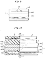
- Fig. 9 shows the structure of the waveguide component 1.
- Fig. 9 corresponds to the section of the waveguide component 1 of the optical waveguide module shown in Fig. 1 along the line A - A.
- This waveguide component 1 comprises a waveguide substrate 110 made of silicon or silica glass, a lower cladding layer 120 (glass material layer) formed on the waveguide substrate 110, the optical waveguides 130 (core or glass material layers) formed on the lower cladding layer 120 to have a predetermined shape, and an upper cladding layer 140 (glass material layer) covering the optical waveguides 130.
- the cladding layers 120 and 140 have refractive indices lower than that of the optical waveguides 130.
- the structure of the waveguide component 1 utilized in this optical waveguide module is not limited to the buried type waveguide component as shown in Fig. 9, but waveguide components (e.g., ridge type waveguides) having various types of structures, as disclosed in, e.g., "Optical Integrated Circuit” (published by Ohm Sha, February 25, 1985, p. 204), can be adopted.
- waveguide components e.g., ridge type waveguides
- Optical Integrated Circuit published by Ohm Sha, February 25, 1985, p. 204
- Fig. 10 is an enlarged sectional view of the connecting portion 13 of the buried type waveguide component 1 having a sectional structure shown in Fig. 9 and the ferrule 3 having the structure described above. This sectional view coincides the sectional view taken along the line B - B of Fig. 2. As shown in Fig.
- the upper surface 1b of the waveguide component 1 and the bottom surface 2b of the reinforcing member 2, the adhering surface 1a of the waveguide component 1 and the adhering face 3c (a surface including the end faces of the cores of the optical fibers at the distal end portion of the ribbon fiber 4) of the ferrule 3, and the side surface 2a of the reinforcing member 2 and the adhering surface 3c of the ferrule 3 are adhered to each other with the ultraviolet-curing or thermosetting adhesive 6 having an adhesion strength of 50 kg/cm 2 or more with respect to silica glass.
- This alignment is an operation of causing the end faces of the cores 410a of the optical fibers, the distal ends of which are held by the ferrule 3, and the end faces of the optical waveguides 130 to coincide with the propagating direction of light.
- a region denoted by reference numeral 11 in Fig. 10 indicates a portion where the optical fibers and the optical waveguides 130 are optically connected to each other.
- a waveguide component 1 may be fixed on a support member 10, as shown in Figs. 11 and 12, thereby reinforcing the strength of an adhering portion 13 of the waveguide component 1 with a ferrule 3.
- This support member 10 is also made of the same material as that of the waveguide substrate 110, e.g., by silicon or silica glass.
- the section of the waveguide component 1 of Fig. 11 along the line F - F coincides with the section of the buried type waveguide component shown in Fig. 9.
- the sectional view of the connecting portion 13 along the line G - G of Fig. 12 is shown in Fig. 13.
- the waveguide component 1 and the support member 10 are fixed to each other by adhesion with an adhesive 6, and an adhering end face 10a of the support member 10 is polished simultaneously during polishing the end face of the waveguide component 1 described above.
- Figs. 14 to 16 show the shapes of various types of optical waveguides 130 formed in the waveguide component 1.
- Each of Figs. 14 to 16 shows a waveguide component 1, from which an upper cladding layer 140 is removed, when viewed from the top.
- optical waveguide patterns are available for realizing optical communication (including optical branching and coupling functions) in various types of modes, e.g., one vs. a multiple of optical waveguides (Fig. 14), a multiple of optical waveguides vs. a multiple of optical waveguides (Fig. 15), and two vs. a multiple of optical waveguides (Fig. 16).
- This optical waveguide module serves as a part of the optical communications systems 20a and/or 20b, as a matter of course. Accordingly, this optical waveguide module has input/output optical fibers to easily realize optical coupling with other transmission lines, as shown in Fig. 17.
- this optical waveguide module has a waveguide component 1 identical to those described above, ferrules 3 fixed to the waveguide component 1 by adhesion, and the input/output optical fibers (in this embodiment, multi-fiber ribbon fibers 4) adhered to the ferrules 3 while their distal ends are inserted in and adhered with through holes 340 of the ferrules 3 with an adhesive 5.
- each of the input/output ribbon fibers 4 is fixed to another ferrule 30 by adhesion with an adhesive 50 to enable optical coupling with a transmission line in the network 20a or 20b.
- These transmission lines 20a and 20b include, in addition to optical fibers 210 and 220 for propagating optical signals, transmitters, optical amplifiers, optical multiplexers/demultiplexers, receivers, and the like.
- the optical waveguide module optically coupled to at least one of the optical networks 20a and 20b constitutes part of the transmission line.
- the optical waveguide module provided as part of the transmission line is accommodated in a case having a predetermined case, as disclosed in, e.g., Japanese Patent Laid-Open No. 62-73210, to protect its connecting portion 13.
- This optical waveguide module may be protected by being molded with a resin, as disclosed in European Patent Laid-Open No. 0 422 445 A1.
- a planar waveguide component obtained by forming eight linear optical waveguides (core diameter: 7 ⁇ m x 7 ⁇ m, difference in specific refractive index: 0.3 %) on a silicon (Si) substrate at a pitch of 250 ⁇ m was prepared so that variations in loss caused by the optical waveguides 130 need not be considered.
- Fig. 18 shows the shape of the optical waveguides of this waveguide component.
- the ferrule 3 made of a plastic material having a different thermal expansion coefficient from that of the waveguide component 1 having this silicon substrate was prepared.
- the cores of the optical fibers held by the ferrule 3 were placed opposite the optical waveguides 130 and aligned with them, and the optical fibers were fixed with an ultraviolet-curing adhesive.
- an ultraviolet-curing adhesive Several types of samples (optical waveguide modules for comparison of characteristics) were fabricated in this manner.
- As the adhesive one having a breaking strength of 100 kg/cm 2 or more with respect to silica glass was utilized to avoid, as much as possible, variations caused by insufficient strength of the adhesive. An adhesion strength of at least 50 kg/cm 2 suffices.
- Table 1 shows the materials used in the fabricated ferrules and the values representing their physical properties.
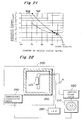
- Figs. 19 and 20 show the values representing physical properties of plastics 1 to 4 shown in Table 1.
- the axis of abscissa represents the amount (weight %, expressed as wt% in Fig. 19) of the contained silica filler, and the axis of ordinate represents the thermal expansion coefficient (/°C) of the plastic material.
- the axis of abscissa represents the amount (weight %, expressed as wt% in Fig. 20) of the contained a silica filler, and the axis of ordinate represents the modulus of elasticity (kg/mm 2 ) of the plastic material.
- Figs. 19 show the values representing physical properties of plastics 1 to 4 shown in Table 1.
- the axis of abscissa represents the amount (weight %, expressed as wt% in Fig. 19) of the contained silica filler
- the axis of ordinate represents the thermal expansion coefficient (/°C) of the plastic material.
- Fig. 21 shows the effective thermal expansion coefficient
- a curve 501 (plotted by solid circles) indicates the effective thermal expansion coefficients of the respective plastic materials with respect to silicon (Si)
- a curve 502 (plotted by hollow circles) indicates the effective thermal expansion coefficients of the respective plastic materials with respect to silica glass (SiO 2 ).
- ⁇ L indicates a difference in thermal expansion coefficient between silicon or silica glass (material that forms the waveguide substrate) and each plastic material (material forming the ferrule)
- E 1 indicates the modulus of elasticity of silicon or silica glass
- E 2 indicates the modulus of elasticity of each plastic material. Therefore, from Fig.
- the thermal expansion coefficient of a plastic material containing 75 weight % or more of a silica filler is 10 x 10 -6 °C -1 or less
- the thermal expansion coefficient of a plastic material containing 85 weight % or more of a silica filler is 6 x 10 -6 °C -1 or less. Since the theoretical limit value of the content of the silica filler is 96 volume %, as described previously, the thermal expansion coefficient of the plastic material is 3 x 10 -6 °C -1 or more (see Fig. 19). Roughly, the 96 volume % as the silica filler content can be regarded as the 96 weight % as the silica filler content.
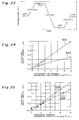
- a change in loss caused by temperature variations was evaluated by using a measuring system shown in Fig. 22.
- An optical waveguide module 123 to be measured is accommodated in a temperature-controlled bath 250 of an environment unit 200. While light having a predetermined intensity is supplied from an LED 230 to input/output optical fibers on one side (optically connected to the input end faces of the optical waveguides), the intensities of light passing through the optical waveguides and then through the input/optical fibers on the other side (optically connected to the output end faces of the optical waveguides 130) are measured by an optical power meter 220, thereby obtaining the variation amount of the coupling loss caused by temperature variations.
- the optical power meter 220 is controlled by a personal computer 210 (PC).
- the temperature in the temperature-controlled bath 250 is adjusted by a temperature controlling means 240 so that it changes as is shown in Fig. 23.
- the temperature controlling means 240 is also controlled by the personal computer 210. More specifically, the temperature changes between -40°C and +75°C, and the rate of change is ⁇ 1.5°C/min.
- Table 2 shows the variation amount of the coupling loss occurring between the waveguide component and the ferrule caused by the above temperature change.
- Table 2 Combination of Materials (Material of Substrate/Material of Ferrule) Maximum Variation (dB) Minimum Variation (dB) Average (dB) Si/Plastic 1 0.39 0.27 0.33 Si/Plastic 2 0.14 0.07 0.10 Si/Si 0.08 0.03 0.05 Si/Plastic 3 0.12 0.05 0.07 Si/Plastic 4 0.10 0.04 0.05
- the materials forming the waveguide substrate 110 and the ferrule 3 are the same (e.g., Si/Si: a case wherein the material of both the substrate and ferrule is silicon), it is ideal as there is no thermal expansion coefficient difference due to the material.
- the variation amount in coupling loss will be almost less than 0.1 dB.
- the variation amount in coupling loss is 0.08 dB.
- the difference in thermal expansion coefficient between the two materials is large, e.g., in the case of "Si/plastic 1" shown in Table 2, the variation amount in coupling loss becomes considerably large, as a matter of course.
- Fig. 24 is a graph showing the positional shift amount between the waveguide component 1 and the optical fibers fixed by the ferrule 3, which is obtained by calculation based on the variation amount in this coupling loss, as a function of the thermal expansion coefficient.
- a line segment obtained by plotting the calculated values of the positional shift amount is indicated by reference numeral 503
- a line segment obtained by plotting the experimental values of the positional shift amount is indicated by reference numeral 504.
- the actual positional shift is smaller than the value obtained by calculation. This is supposed to be due to a relative decrease in positional shift amount caused by elastic deformation of both the material of the waveguide substrate and the material of the ferrule.
- Fig. 25 shows the positional shift amount calculated by considering this ratio of the modulus of elasticity of the material forming the waveguide substrate 110 to the modulus of elasticity of the material forming the ferrule 3.
- a line segment obtained by plotting the calculated values of the positional shift amount is indicated by reference numeral 505
- a line segment obtained by plotting the experimental values of the positional shift amount is indicated by reference numeral 506.
- the axis of abscissa represents the effective thermal expansion coefficient (the ratio of a difference in thermal expansion coefficient between the materials forming the waveguide substrate and the ferrule to the ratio of the modulus of elasticity of the material forming the waveguide substrate to the modulus of elasticity of the material forming the ferrule).
- the tolerance of positional shift also depends on the gaps among the cores of the optical fibers (in this embodiment, a multi-fiber ribbon fiber 4) held by the ferrule 3.
- the distance between the cores at the two ends is 3.75 mm.
- of the material forming the ferrule 3 with respect to the material forming the waveguide substrate 110 must be set to less than 3.0 x 10 -6 °C -1 . Preferably, it is set to less than 2.7 x 10 -6 °C -1 .
- silicon or silica glass is used as the material of the waveguide substrate 110 constituting part of the waveguide component 1.
- a structure obtained by forming buried type silica glass-based waveguides on this waveguide substrate has extensively been developed as its coupling loss with respect to optical fibers is low and the transmission loss of its interior is small.
- the physical properties of these material are shown in Table 1 described above.
- a phenol-based epoxy resin containing a silica glass filler is often used in the manufacture of the ferrule 3.
- the thermal expansion coefficient of this material can be changed by changing the content of the filler and the like.
- the modulus of elasticity of the epoxy resin can be adjusted within the range of 1,500 to 5,000 kg/mm 2 by adjusting the content of the filler.
- the thermal expansion coefficient of this material must be set to 10 x 10 -6 °C -1 or less.
- a difference in effective thermal expansion coefficient obtained by considering actual elastic deformation is less than 3 x 10 -6 °C -1 .
- a resin having a difference in thermal expansion coefficient of this level includes, e.g., LCR305 manufactured by ICI.
- sample 1 As the material to form a ferrule 3, a phenol-based epoxy resin material having a thermal expansion coefficient of 6.0 x 10 -6 °C -1 and a modulus of elasticity of 2,500 kg/mm 2 was used. The effective thermal expansion coefficient of this material with respect to silicon is 2.25 x 10 -6 °C -1 .
- a waveguide component 1 was fabricated by forming an 8-branched single-mode optical waveguide 130 on a waveguide substrate 110 which was formed by combining FHD and RIE.
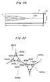
- Fig. 26 shows the shape of the waveguide of the manufactured optical waveguide 130.
- a ferrule 3 holding one optical fiber (the distal end portion of this optical fiber is fixed to the ferrule with an adhesive) and a ferrule 3 holding a ribbon fiber on which eight optical fibers are arranged and fixed at a pitch of 250 ⁇ m (the distal end portion of this ribbon fiber was fixed to the ferrule with an adhesive) were respectively connected to input/output end faces 1a and 1c of the waveguide component 1.
- Five optical waveguide modules each obtained in this manner were fabricated as Sample 1. Alignment had been performed in accordance with the method already described above.
- an ultraviolet-curing adhesive having an adhesion strength of 100 kg/cm 2 or more with respect to silica glass was employed.
- the ultraviolet-curing adhesive is doped with a thermosetting catalyst, thereby the adhesive has a predetermined thermosetting property.
- the optical waveguide modules (Sample 1) obtained in the above manner had an insertion loss of 10.1 dB at average and an excessive loss (a total transmission loss including branching loss and the like in the optical waveguide 130) of 1.1 dB.
- These optical waveguide modules (Sample 1) were measured by employing the measuring system shown in Fig. 22 within a temperature range of -40° to 75°C with a temperature change pattern shown in Fig. 23. As measurement light, light having a wavelength of 1.3 ⁇ m was used. As the result of this measurement, it was confirmed that the respective optical waveguide modules of Sample 1 had good temperature characteristics with the variation amount in coupling loss of 0.2 dB at average and 0.3 dB at maximum.
- Sample 2 as the material to form a ferrule 3, a phenol-based epoxy resin material having a thermal expansion coefficient of 4.5 x 10 -6 °C -1 and a modulus of elasticity of 3,300 kg/mm 2 was used.
- the effective thermal expansion coefficient of this material with respect to silicon is 1.74 x 10 -6 °C -1 .
- a waveguide component 1 was fabricated by forming an 8-branched single-mode optical waveguide 130 on a waveguide substrate 110 which was formed by combining FHD and RIE.
- Fig. 26 shows the shape of the waveguide of the manufactured optical waveguide 130.
- a ferrule 3 holding one optical fiber (the distal end portion of this optical fiber is fixed to the ferrule with an adhesive) and a ferrule 3 holding a ribbon fiber on which eight optical fibers are arranged and fixed at a pitch of 250 ⁇ m (the distal end portion of this ribbon fiber was fixed to the ferrule with an adhesive) were respectively connected to input/output end faces 1a and 1c of the waveguide component 1.
- Five optical waveguide modules each obtained in this manner were fabricated as Sample 2. Alignment had been performed in accordance with the method already described above.
- an ultraviolet-curing adhesive having an adhesion strength of 100 kg/cm 2 or more with respect to silica glass was employed.
- the ultraviolet-curing adhesive is doped with a thermosetting catalyst, thereby the adhesive has a predetermined thermosetting property.
- the optical waveguide modules (Sample 2) obtained in the above manner had an insertion loss of 10.0 dB at average and an excessive loss of 1.0 dB.
- These optical waveguide modules (Sample 2) were measured by employing the measuring system shown in Fig. 22 within a temperature range of -40° to 75°C with a temperature change pattern shown in Fig. 23. As measurement light, light having a wavelength of 1.3 ⁇ m was used. As the result of this measurement, it was confirmed that the respective optical waveguide modules of Sample 2 had good temperature characteristics with the variation amount in coupling loss of 0.2 dB at average and 0.25 dB at maximum.
- Optical waveguide modules each obtained by fixing, by adhesion, one of the following plastic ferrules on a waveguide component 1 constituted by a silica glass substrate will be described.
- Sample 3 as the material to form the ferrule 3, a phenol-based epoxy resin material having a thermal expansion coefficient of 4.5 x 10 -6 °C -1 and a modulus of elasticity of 3,300 kg/mm 2 was used.
- the effective thermal expansion coefficient of this material with respect to silica glass is 1.89 x 10 -6 °C -1 .
- the waveguide component 1 was fabricated by forming an 8-branched single-mode optical waveguide 130 on a waveguide substrate 110 which was formed by combining FHD and RIE.
- Fig. 26 shows the shape of the waveguide of the manufactured optical waveguide 130.
- a ferrule 3 holding one optical fiber (the distal end portion of this optical fiber is fixed to the ferrule with an adhesive) and the ferrule 3 holding a ribbon fiber on which eight optical fibers are arranged and fixed at a pitch of 250 ⁇ m (the distal end portion of this ribbon fiber was fixed to the ferrule with an adhesive) were respectively connected to input/output end faces 1a and 1c of the waveguide component 1.
- Five optical waveguide modules each obtained in this manner were fabricated as Sample 3. Alignment had been performed in accordance with the method already described above.
- an ultraviolet-curing adhesive having an adhesion strength of 100 kg/cm 2 or more with respect to silica glass was employed.
- the optical waveguide modules (Sample 3) obtained in the above manner had an insertion loss of 10.6 dB at average and an excessive loss of 1.6 dB.
- These optical waveguide modules (Sample 3) were measured by employing the measuring system shown in Fig. 22 within a temperature range of -40° to 75°C with a temperature change pattern shown in Fig. 23. As measurement light, light having a wavelength of 1.3 ⁇ m was used. As the result of this measurement, it was confirmed that the respective optical waveguide modules of Sample 3 had good temperature characteristics with the variation amount in coupling loss of 0.11 dB at average and 0.18 dB at maximum.
- the temperature characteristics of Sample 3 are further superior to those of Samples 1 and 2 described above. This is supposed to be due to a decrease in stress applied to the waveguide substrate 110 and waveguide glass layers (120, 130, and 140), which is caused by employing silica glass as the material of the waveguide substrate 110.
- each of Samples 1 to 3 satisfies the specifications of the temperature characteristics of a component capable of being used indoors (10 cycles (48 hours) with temperature fluctuation from -10°C to 60°C) and the specifications of the temperature characteristics of TR-NWT-001209 manufactured by Bellcore (42 cycles (336 hours) with temperature variations from -40°C to 75°C) described above.
- the material to form the ferrule of this comparative example is a plastic material having a thermal expansion coefficient of 15.2 x 10 -6 °C -1 and a modulus of elasticity of 2,000 kg/mm 2 .
- the effective thermal expansion coefficient of this material with respect to silicon is 6.6 x 10 -6 °C -1 , which exceeds 3.0 x 10 -6 °C -1 .
- five optical waveguide modules were fabricated each by fixing by adhesion a waveguide component 1 having an 8-branched optical waveguide 130 and a ferrule made of the above plastic material with each other.
- the insertion loss and excessive loss of this case at room temperature were 10.0 dB and 1.0 dB, respectively, exhibiting low loss characteristics.
- the variation amount in loss was 0.8 dB at maximum, which was twice or more that of the above examples. This is supposed to be caused by an increase in positional shift between the cores due to thermal expansion accompanying the temperature variations.
- Fig. 27 is a conceptual view schematically showing a packing model of spherical fillers. Secondary balls 600b, tertiary balls 600c, and fourth balls 600d are sequentially packed in gaps formed by largest-diameter primary balls 600a. Accordingly, the above theoretical value of 96 volume % indicates the limit value that allows a resin, e.g., a plastic, to be filled in the gaps of the fillers.
- the present inventors prepared ferrules 3 made of a phenol-based epoxy resin respectively containing 70, 80, 90, and 94 weight % of a silica filler, and fixed then by adhesion each on a 1 x 8 branched waveguide component 1 having a waveguide substrate 110, thereby fabricating optical waveguide modules as samples.
- the moist heat characteristics of these optical waveguide modules were measured in an environment having a temperature of 75°C and a relative humidity (RH) of 95% (for example, the specification of the moist heat characteristics of TR-NWT-001209 manufactured by Bellcore is 60°C, 95RH, and 336 hours, and the specification of the moist heat characteristics of TA-NWT-001221 manufactured by Bellcore is 75°C, 90 ⁇ 5RH, and 5000 hours).
- RH relative humidity
- a low-cost plastic material which can be molded continuously and the thermal expansion coefficient and modulus of elasticity of which have a predetermined relationship with those of a material forming a waveguide substrate, is used as a material to form a ferrule, in place of a material, e.g., glass, which is difficult to machine. Therefore, an optical waveguide module having sufficient characteristics against temperature variations can be obtained.
- an optical waveguide module also having excellent moist heat characteristics can be obtained.
Abstract
Description
- The present invention relates to an optical waveguide module comprising at least a ferrule for holding one end of an optical fiber and a waveguide component having an optical waveguide on a substrate made of a material different from that of the ferrule and serving as an optical component and, more particularly, to a ferrule capable of obtaining good temperature characteristics and good moist heat characteristics in terms of a relationship with the material of the substrate, an optical waveguide module utilizing this ferrule and the optical component, and a method of manufacturing this optical waveguide module.
- Along with the recent development in the optical communication technique, demands have arisen for branching or multiplexing/demultiplexing elements which branch or multiplex light having a predetermined wavelength. Silica glass-based planar optical waveguide circuits (waveguide components) are used to satisfy demands for a higher packing density of these optical components. A planar optical waveguide has a low waveguide loss (a transmission loss accompanying optical branching and the like) and enables low-loss connection with an optical fiber.
- As the planar optical waveguide, for example, Japanese Patent Laid-Open No. 58-105111 discloses a buried type silica-based waveguide component obtained by a scheme of forming a glass film in accordance with, e.g., flame hydrolysis (FHD), thereafter forming a circuit pattern in accordance with reactive ion etching (RIE) which is an application of a semiconductor technique, and forming a film of a cladding portion.
- When such a waveguide component is to be utilized in an optical component (e.g., an optical waveguide module), input/output optical fibers are generally connected to an optical waveguide formed in this waveguide component. In connecting the waveguide component and the optical fibers, generally, a silica-based ferrule, which is precision-machined and in which optical fibers are fixed is used, as indicated in, e.g., IEEE Photonic Technology Letters, vol. 4, No. 8, (1992), pp. 906 - 908. The end face of the silica-based ferrule is fixed by adhesion to the end face of the waveguide component by using an ultraviolet-curing adhesive.
- For example, Japanese Patent Laid-Open No. 6-51155 discloses a technique for forming a ferrule with silica glass which transmits ultraviolet rays therethrough and solidifying an adhesive between the end faces of the ferrule and waveguide component with each other uniformly within a short period of time, thereby shortening the work time and decreasing the possibility of misalignment between the end faces of the ferrule and waveguide component.
- In optically connecting one or more optical fibers and one or more optical waveguides formed in a waveguide component with each other, it is most important to decrease a transmission loss which is caused by the positional displacement of this connecting portion (the positional displacement between the end faces of the cores of the optical fibers and the end faces of the optical waveguides opposing the end faces of the cores through an adhesive) (a transmission loss at this connecting portion will be referred to as a coupling loss hereinafter). For example, an optical waveguide formed in the waveguide component has a diameter (core diameter) of 10 µm or less. In order to suppress the coupling loss between this optical waveguide and an optical fiber (the core of the optical fiber) to less than 0.3 dB, the positional shift amount at the connecting portion must be suppressed within 1 µm. On the other hand, in an optical waveguide module in which a waveguide component (especially a waveguide substrate) and a ferrule which are made of materials having different thermal expansion coefficients are fixed by adhesion with an adhesive having a predetermined strength, when the temperature of the environment varies, the end faces of the cores of the optical waveguide and of the optical fibers are misaligned from each other.
- Hence, in order to obtain an optical waveguide module that can be used in a severe environment (for example, with the temperature characteristic specifications of a component used indoors, 10 cycles (48 hours) with temperature variations from -10°C to 60°C; with the temperature characteristic specifications of TR-NWT-001209 manufactured by Bellcore, 42 cycles (336 hours) with temperature variations from -40°C to 75°C), a ferrule for holding the end portions of optical fibers is generally made of silica glass having a thermal expansion coefficient almost equal to that of the material of the waveguide substrate, as described above, so that desired temperature characteristics and moist heat characteristics can be obtained. Fig. 29 is a graph showing the relationship, in a single-mode optical waveguide having a mode field diameter of 10 µm, between the positional shift amount between the end faces of the optical waveguides and the end faces of the cores of the optical fibers and the transmission loss of the optical waveguide.
- However, in consideration of only the manufacturing technique of the ferrule, when an optical waveguide module is to be manufactured with silica glass described above, a material, e.g., glass, which is difficult to machine must be machined at high precision within 1 µm, as disclosed in the above official gazettes (machining of grooves for fixing the positions of optical fibers). Furthermore, the ferrule must be constituted by a plurality of constituent members (the end portions of the optical fibers must be sandwiched by upper and lower silica glass plates) to clamp the end portions of the optical fibers. When a ferrule is to be formed of a plastic material, it can be molded with a single step by plastic molding, and through holes (having continuous inner walls) that define the positions of the optical fibers upon insertion of the end portions of the optical fibers can also be formed at high precision during this plastic molding, as described in, e.g., "DEVELOPMENT OF 16-FIBER CONNECTORS FOR HIGH-SPEED LOW-LOSS CABLE CONNECTION" (INTERNATIONAL WIRE AND CABLE SYMPOSIUM PROCEEDINGS 1993, pp. 244 - 249). When the ferrule is formed of the plastic material, in this manner, the end portions of the optical fibers need not be clamped by preparing a plurality of members for the purpose of obtaining the clamping structure of the end portions of the optical fibers (since through holes that define the positions of the end portions of the optical fibers can be formed simultaneously during plastic molding, the positioned distal ends of the optical fibers need not be vertically sandwiched and clamped). Also, no high-precision machining technique is required (since the through holes are formed in units of the optical fibers at high precision, precision machining, e.g., formation of grooves for fixing the positions of optical fibers in the clamping members, is not needed). Therefore, this plastic material is suitable as the material of the ferrule.
- The present invention has been made in view of the above situations, and has as its object to provide an optical waveguide module which utilizes a ferrule made of a low-cost plastic material that can be continuously molded and high-precision machined easily, in place of a material, e.g., glass, which is difficult to machine, comprises a waveguide component (in particular, a waveguide substrate) and a ferrule made of materials having different thermal expansion coefficients, and which has stable temperature characteristics and moist heat characteristics even in a severe environment; and a method of manufacturing the same.
- An optical waveguide module of the present invention comprises a waveguide component obtained by forming an optical waveguide constituting at least part of a transmission line for propagating light having a predetermined wavelength on a waveguide substrate made of the first material (e.g., silicon or silica glass is suitable as the first material), and a ferrule made of the second material (e.g., a plastic material is suitable as the second material) and fixed with an adhesive having a predetermined strength such that an end face thereof opposes the end face of the waveguide component while holding one end of an optical fiber (the end portion of the optical fiber is placed as it is inserted in a through hole having a continuous inner wall), so as to optically couple the optical fiber constituting at least part of the transmission line and the optical waveguide of the waveguide component. This optical waveguide module further comprises an input/output optical fiber fixed by adhesion in the ferrule such that its end portion is inserted in the through hole of the ferrule. With this arrangement, branching or multiplexing of signal light from an existing transmission line or to the transmission line is easily realized. The optical fiber is constituted by a core for propagating light having a predetermined wavelength, and a cladding layer covering the core. Normally, the optical fiber is utilized while the surface of the cladding layer is covered with a polyacrylate-based resin. The surface of the resin coating may be further covered with a plastic. The optical fiber is not limited to a single-fiber fiber but includes a ribbon fiber (for example, a 8-fiber ribbon fiber as shown in Figs. 7 and 8) obtained by integrally covering a plurality of optical fibers (each optical fiber may be coated with a polyacrylate-based resin colored in different colors) with a plastic material.
- In particular, in order to realize an optical waveguide module whose coupling loss is 0.3 dB or less even under severe temperature variations (e.g., temperature variations within a range of -40° to +75°C), the first material to form the substrate portion of the waveguide component and the second material to form the ferrule satisfy a relation:

- When the plastic material to form the ferrule is a phenol-based epoxy resin containing a predetermined amount of silica filler, it suffices if its thermal expansion coefficient is 10 x 10-6 (°C-1) or less. In order to obtain further superior temperature characteristics, this thermal expansion coefficient is preferably 6 x 10⁻⁶ (°C-1) or less.
- It suffices if the content of the silica filler contained in this phenol-based epoxy resin is 85 weight % or more and 95 weight % or less. In order to obtain further superior moist heat characteristics, this content is preferably 90 weight % or more and 95 weight % or less. At this time, the modulus of elasticity of the above phenol-based epoxy resin is 5,000 (kg/mm2) or less.
- As the adhesive used for fixing the end face of the optical waveguide and the end face of the optical fiber with each other by adhesion, an ultraviolet-curing adhesive or thermosetting adhesive having an adhesion strength of 50 (kg/cm2) or more with respect to silica glass is employed. Furthermore, an adhesive having both ultraviolet-curing and thermosetting properties can be used.
- In a method of manufacturing the above optical waveguide module of the present invention, a waveguide component in which an optical waveguide constituting at least part of a transmission line for propagating light having a predetermined wavelength is formed on a waveguide substrate made of the first material, and a ferrule made of the second material and fixed with an adhesive to the end portion of an optical fiber (including input/output optical fibers) constituting at least part of the transmission line, while the end portion of the optical fiber is inserted in a through hole having a continuous inner wall are prepared. At this time, the effective thermal expansion coefficient

- The end face of the waveguide component and the end face of the ferrule are abutted with each other and are adhered to each other with an adhesive, e.g., an ultraviolet-curing or thermoset adhesive having an adhesion strength of 50 (kg/cm2) or more with respect to silica glass. Thus, the end face of the optical waveguide of this waveguide component and the end face of the core of the optical fiber, the position of the end portion of which is defined by the through hole of the ferrule, are aligned with each other. Thereafter, ultraviolet rays are irradiated on this adhering portion for a predetermined period of time, and/or this adhering portion is heated to a predetermined temperature, thereby solidifying the adhesive.
- As described above, The ferrule according to the present invention is made of a phenol-based epoxy resin containing a predetermined amount of silica filler and having a thermal expansion coefficient of 10 x 10-6 (°C-1) or less, preferably 6 x 10⁻⁶ (°C-1) or less. The content of the silica filler is 85 weight % or more and 95 weight % or less, and preferably 90 weight % or more and 95 weight % or less. The plastic material to form this ferrule is preferably a phenol-based epoxy resin having a modulus of elasticity of 5,000 (kg/mm2) or less.
- When this optical waveguide module is constituted by utilizing the respective constituent members made of different materials, e.g., a waveguide substrate made of silicon or silica glass and a ferrule made of a plastic material, if the effective thermal expansion coefficient of the material forming the ferrule with respect to the material forming the waveguide substrate is set to 3 x 10⁻⁶ (°C-1) or less, as indicated by the above equation (1), the shift amount between the end faces of the cores which is caused by temperature variations can be suppressed to 1 µm or less, that is, the coupling loss can be suppressed to 0.3 dB or less. At least, the present inventors confirmed that, in order to obtain a ferrule that can be applied to a silica glass substrate constituting part of the waveguide component (in order to satisfy the above conditions), the ferrule had to be made of a plastic material (having a thermal expansion coefficient of 3 x 10⁻⁶ °C-1 or more and 10 x 10-6 °C-1 or less) containing at least 75 weight % of a silica filler, and that in order to obtain a ferrule that can be applied to a silicon substrate, the ferrule must be made of a plastic material (having a thermal expansion coefficient of 3 x 10⁻⁶ °C-1 or more and 10 x 10-6 °C-1 or less) containing at least 85 weight % of a silica filler. It was also confirmed that at this time the optical waveguide module having the above arrangement could obtain good temperature characteristics.
- On the other hand, "Kogyo Zairyo" December issue, 1994 (Vol. 42, No. 15, pp. 112 - 116) shows that the theoretical limit value of a silica filler that can be contained in a plastic material is 96 volume %. The present inventors have already obtained a plastic ferrule containing 94 weight % of a silica filler. Furthermore, the present inventors performed evaluation of the moist heat characteristics of an optical waveguide module constituted by a silica glass waveguide substrate and a plastic ferrule under predetermined conditions, and confirmed that the lower limit of the silica filler contained in the plastic material was between 80 weight % and 90 weight %. Since the theoretical limit value of the content of the silica filler is 96 volume %, the lower limit of the thermal expansion coefficient of the plastic material as the material to form the ferrule is 3 x 10⁻⁶ (°C-1) (see Fig. 19). The 96 volume % as the silica filler content can be roughly regard as the 96 weight % as the silica filler content.
- Therefore, when either a silicon substrate or a silica glass substrate may be utilized, if a plastic material containing at least 85 weight % to 95 weight % of a silica filler is employed as the material to form the ferrule, an optical waveguide module having both good temperature characteristics and good moist heat characteristics can be obtained.
- In particular, when the material to form the ferrule on a silica glass substrate is determined to be a phenol-based epoxy resin containing a predetermined amount of silica filler and having a thermal expansion coefficient of 10 x 10-6 (°C-1) or less and the material to form the ferrule on a silicon substrate is defined to be a phenol-based epoxy resin containing a predetermined amount of silica filler and having a thermal expansion coefficient of 6 x 10⁻⁶ (°C-1) or less, an optical waveguide module can be obtained which satisfies the temperature characteristic specifications of a component used indoors described above (10 cycles (48 hours) with temperature variations from -10°C to 60°C), and the temperature characteristic specifications of TR-NWT-001209 manufactured by Bellcore (42 cycles (336 hours) with temperature variations from -40°C to 75°C).
- When the content of the silica filler is adjusted to 90 weight % or more and 95 weight % or less, an optical waveguide module which reliably satisfies the moist heat characteristics (60°C, 95 RH, 336 hours) of TR-NWT-001209 manufactured by Bellcore can be obtained.
- The present invention will become more fully understood from the detailed description given hereinbelow and the accompanying drawings which are given by way of illustration only, and thus are not to be considered as limiting the present invention.
- Further scope of applicability of the present invention will become apparent from the detailed description given hereinafter. However, it should be understood that the detailed description and specific examples, while indicating preferred embodiments of the invention, are given by way of illustration only, since various changes and modifications within the spirit and scope of the invention will become apparent to those skilled in the art form this detailed description.
-
- Fig. 1 is a view for explaining the assembling process of an optical waveguide module according to the first embodiment of the present invention;
- Fig. 2 is a perspective view showing the structure of the optical waveguide module according to the first embodiment of the present invention;
- Fig. 3 is a developed view of a ferrule for explaining the structure of the ferrule;
- Fig. 4 is a view showing the sectional structure of the ferrule shown in Fig. 3 along the line C - C of Fig. 3;
- Fig. 5 is an enlarged view of the main part of the section of the ferrule shown in Fig. 4;
- Fig. 6 is a view for explaining the aligning method of the optical waveguide module of the present invention;
- Fig. 7 is a perspective view for explaining the structure of the distal end portion of a ribbon fiber;
- Fig. 8 is a view showing the sectional structure of the ribbon fiber shown in Fig. 7 taken along the line E - E of Fig. 7;
- Fig. 9 is a view showing the sectional structure of a waveguide component shown in Figs. 1 and 2 along the line A - A of Fig. 1;
- Fig. 10 is a view showing the sectional structure of the optical waveguide module shown in Fig. 2 along the line B - B of Fig. 2;
- Fig. 11 is a view for explaining the assembling process of an optical waveguide module according to the second embodiment of the present invention;
- Fig. 12 is a perspective view showing the structure of the optical waveguide module according to the second embodiment of the present invention;
- Fig. 13 is a view showing the sectional structure of the optical waveguide module shown in Fig. 12 along the line G - G of Fig. 12;
- Fig. 14 is a view showing a waveguide pattern (No. 1) formed on a waveguide component;
- Fig. 15 is a view showing a waveguide pattern (No. 2) formed on a waveguide component;
- Fig. 16 is a view showing a waveguide pattern (No. 3) formed on a waveguide component;
- Fig. 17 is a view showing the entire arrangement of an optical communications system comprising optical waveguide modules according to the present invention;
- Fig. 18 is a view showing the waveguide pattern of a waveguide component fabricated as an experimental sample;
- Fig. 19 is a graph showing the relationship between the content of silica filler (weight %) and a thermal expansion coefficient (/°C) as the values representing the physical properties of a material (plastic) forming a ferrule;
- Fig. 20 is a graph showing the relationship between the content of silica filler (weight %) and a modulus of elasticity (kg/mm2) as the values representing the physical properties of the material (plastic) forming the ferrule;
- Fig. 21 is a graph showing the relationship between the content of silica filler (weight %) and an effective thermal expansion coefficient (

- Fig. 22 is a diagram showing the arrangement of a measuring system that measures the temperature characteristics of the optical waveguide module according to the present invention;
- Fig. 23 is a graph showing the pattern of temperature variations obtained by the measuring system shown in Fig. 22;
- Fig. 24 is a graph showing the relationship between a difference in the thermal expansion coefficient (calculated value and actually measured value) between a material forming a waveguide substrate and a material forming the ferrule and the positional shift amount of the cores at the adhering portion of an optical waveguide module constituted by using these waveguide substrate and ferrule;
- Fig. 25 is a graph showing the relationship between the effective thermal expansion coefficient (calculated value and actually measured value) of the material forming the ferrule with respect to the material forming the waveguide substrate and the positional shift amount of the cores at the adhering portion of the optical waveguide module constituted by using these waveguide substrate and ferrule;
- Fig. 26 is a view showing a waveguide pattern of a waveguide component fabricated as an example of the optical waveguide module according to the present invention;
- Fig. 27 is a conceptual view schematically showing the packing model of the silica filler;
- Fig. 28 is a graph showing a result obtained by measuring the moist heat characteristics of the optical waveguide module according to the present invention; and
- Fig. 29 is a graph showing a coupling loss caused by a positional shift between the optical fiber and an optical waveguide.
- The preferred embodiments of the present invention will be described with reference to Figs. 1 to 29. Note that the same portions are denoted by the same reference numerals throughout the drawings, and a detailed description thereof will be omitted.
- Fig. 1 is a view for explaining the assembling process of an optical waveguide module according to the present invention, and Fig. 2 is a perspective view showing the entire arrangement of the optical waveguide module according to the present invention. In a method of manufacturing the optical waveguide module according to the present invention, first, a
ferrule 3, to which the end portion of an input/output ribbon fiber 4 is fixed by adhesion with an adhesive 5 as exposed optical fibers of theribbon fiber 4 are inserted in through holes, and awaveguide component 1 having, on a waveguide substrate, optical waveguides (cores) for propagating light having a predetermined wavelength are prepared. A reinforcingmember 2 is prepared to obtain a sufficiently high adhesion strength between theferrule 3 and thewaveguide component 1. The reinforcingmember 2 has abottom surface 2b fixed by adhesion on an upper surface 1b of thewaveguide component 1 with an adhesive and aside surface 2a opposing an adheringend face 3c of theferrule 3. - An adhering end face 1a of the
waveguide component 1 having the upper surface 1b to which the reinforcingmember 2 has already been fixed by adhesion and the adheringend face 3c of theferrule 3 that holds the end portions of the expose optical fibers of theribbon fiber 4 are optically polished by sequentially performing the following steps. The adhering surface (side surface) 2a of the reinforcingmember 2 is polished simultaneously during polishing the end face of thewaveguide component 1, and the end faces of the cores of the optical fibers fixed by theferrule 3 are also polished simultaneously during polishing the end face of theferrule 3. - First Step (Rough Polishing Step):
- Each end face is exposed by polishing with coarse abrasive paper of #800 to #2,000.
- Second Step (Intermediate Polishing Step):
- Surface scars on each end face are removed with diamond abrasive grains of 6 to 9 µm.
- Third Step (Finish Polishing Step):
- The surface scars on each end face are further removed with diamond abrasive grains of 1 to 3 µm.
- Fourth Step (Buff Polishing Step):
- A layer on the surface of each end face which is denatured by processing is removed by cesium oxide grains or silicon dioxide grains of 0.3 µm or less.
- In these polishing steps, the angle of each end face may be shifted with respect to the propagation direction (this direction coincides with a direction to insert the
ribbon fiber 4 into the ferrule 3) at an adhering or connectingportion 13 from 90° in accordance with the necessity of decrease or the like of the amount of optical attenuation which is caused by reflection of the end face. Angle adjustment required in this case is performed in the first step. A polishing method other than the above polishing method is also known. Thus, a polishing method will be selected as required. - Subsequently, the input/output end face 1a of the
waveguide component 1 and the adheringend face 3c of theferrule 3 are abutted against each other and adhered to each other with an adhesive 6. The end faces of the optical waveguides formed in thewaveguide component 1 and the end faces of the cores of the optical fibers of theribbon fiber 4 are aligned. At this time, the optical fibers have already been fixed in theferrule 3 with the adhesive 5 having a predetermined strength, while being inserted in through holes of theferrule 3. Thebottom surface 2b of the reinforcingmember 2 and the upper surface 1b of thewaveguide component 1; and the adheringsurface 2a of the reinforcingmember 2, the adheringsurface 2a of the reinforcingmember 2, and the adhering face 1a of thewaveguide component 1 are adhered to each other with an ultraviolet-curing or thermosetting adhesive having an adhesion strength of 50 kg/cm2 or more, and preferably 100 kg/cm2 or more, with respect to silica glass. Furthermore, an adhesive having both ultraviolet-curing and thermosetting properties can be used if it has an enough adhesion strength such as 50 kg/cm2 or more with respect to silica glass. - In alignment of the end faces of the optical waveguides of the
waveguide component 1 and the end faces of the cores of theoptical fibers 4 with each other, while thewaveguide component 1 is supported by a movable precision stage, light having a predetermined wavelength is caused to be incident on the optical waveguides of thewaveguide component 1 through one input/output end face of thewaveguide component 1, and the intensity of light emerging from the optical fibers optically connected to the other input/output end of thewaveguide component 1 with the adhesive is monitored, as is described in, e.g., U.S.P. No. 4,744,619. More specifically, thewaveguide component 1 is moved such that the optical intensity of the emerging light becomes the maximum, thereby performing alignment. - When alignment of the end faces (constituting part of the input/output end face of the waveguide component 1) of the optical waveguide of the
waveguide component 1 and the end faces (constituting part of the adheringend face 3c of the ferrule 3) of the cores of the optical fibers is completed, the adheringportion 13 is irradiated with ultraviolet rays or is heated to a predetermined temperature, thereby solidifying the adhesive. This series of operations (adhesion of the respective end faces at the adhering portion 13 - alignment - solidification of the adhesive) are performed for each of the two input/output end faces of thewaveguide component 1, thereby obtaining an optical waveguide module as shown in Fig. 2 according to the first embodiment of the present invention. - The structure of the
ferrule 3 will be described with reference to Figs. 3 to 5. Fig. 3 is a developed view showing the structure of thisferrule 3. Referring to Fig. 3,reference symbol 3a denotes the upper surface of theferrule 3; 3b, the side surface thereof; 3c, the front surface (adhering surface) thereof; 3d, the bottom surface thereof; and 3e, the rear surface (in which the distal end of theribbon fibers 4 is inserted) thereof. Awindow 310 is formed in advance in theupper surface 3a of theferrule 3 in order to observe insertion of the distal end (a plurality of optical fibers are exposed by removing a part of ribbon) of theribbon fibers 4 into theferrule 3.Guide grooves 330a are formed in advance in abase portion 330 of theferrule 3 that can be seen through thewindow 310, in order to facilitate insertion of the distal ends of the exposed optical fibers in the throughholes 340. Since the distal end of theribbon fiber 4 and theferrule 3 are fixed by adhesion at thisbase portion 330, thewindow 310 also serves as an introducing port of the adhesive. Anopening portion 320 for allowing insertion of the distal end portion of theribbon fiber 4 into theferrule 3 is formed in therear surface 3e of theferrule 3.Opening portions 340a of the throughholes 340 that are formed in advance are located on theend face 3c (a surface directly opposing the input/output end face 1a of the waveguide component 1) of theferrule 3. - Fig. 4 shows the section of the
ferrule 3 shown in Fig. 3 taken along the line C - C. The distal end portions of the exposed optical fibers of theribbon fiber 4 are inserted into the throughholes 340 of theferrule 3 in the direction of an arrow H through therear surface 3e toward thefront surface 3c. Fig. 5 particularly shows, of the section of theferrule 3 shown in Fig. 4, the enlarged section of one throughhole 340. As is seen from Fig. 5, the interior of each throughhole 340 is constituted by aportion 340b and aportion 340c. Theportion 340b has a much larger diameter than that of each optical fiber to facilitate insertion of the distal end portion of the optical fiber. Theportion 340c has a diameter substantially equal to the diameter of the optical fiber to prevent a positional shift (a positional shift in the horizontal direction with respect to thefront surface 3c) of the distal end portion of the optical fiber. - As has been described previously, the first material (e.g., silicon or silica glass) suitable for forming the substrate of the
waveguide component 1 and the second material (e.g., a plastic material) suitable for forming theferrule 3 are different. Therefore, even if thewaveguide component 1 and theferrule 3 are fixed with each other by adhesion by accurately performing alignment, if the temperature varies in the range of, e.g., -40°C to +75°C, a positional shift occurs between the end faces of the optical waveguides of thewaveguide component 1 and the end faces of the cores of the optical fibers due to the difference in thermal expansion coefficient between the two materials (the coupling loss is increased). - Therefore, according to the present invention, in order to suppress the coupling loss to 0.3 dB or less even under the temperature variations described above, the
ferrule 3 is formed of the second material whose effective thermal expansion coefficient
waveguide component 1 is less than 3 x 10⁻⁶ °C-1. In the formula representing the effective thermal expansion coefficient, ΔL is a difference in thermal expansion coefficient between the first and second materials, E1 is the modulus of elasticity of the first material, and E2 is the modulus of elasticity of the second material. - In particular, the preset inventors have obtained an optical waveguide module having excellent temperature characteristics by combining a waveguide substrate made of silicon or silica glass and a
ferrule 3 made of a phenol-based epoxy resin (containing a predetermined amount of silica filler) having a thermal expansion coefficient of 10 x 10-6 °C-1 or less, or furthermore by a phenol-based epoxy resin (containing a predetermined amount of silica filler) having a thermal expansion coefficient of 6 x 10⁻⁶ °C-1 or less. When theferrule 3 is formed of the phenol-based epoxy resin, the content of the silica filler is preferably 85 weight % to 95 weight %. The present inventors have also confirmed that the content of the silica filler is preferably 90 weight % to 95 weight % to obtain an optical waveguide module having further superior moist heat characteristics. The modulus of elasticity of these phenol-based epoxy resins is 5,000 kg/mm2 or less. - The
ferrule 3 made of the above material is obtained by plastic molding, as is indicated in, e.g., "DEVELOPMENT OF 16-FIBER CONNECTORS FOR HIGH-SPEED LOW-LOSS CABLE CONNECTION" (INTERNATIONAL WIRE AND CABLE SYMPOSIUM PROCEEDINGS 1993, pp. 244 - 249). More specifically, two, i.e., upper and lower dies each having a recess of a predetermined shape are prepared. Metal core pins for forming the through holes in theferrule 3 are gripped by these dies, and the resin described above is injected into a cavity defined by the recesses of the respective dies, thereby obtaining theferrule 3. - When the optical waveguide module shown in Fig. 2 is fabricated with the above material by utilizing the
ferrule 3 having the structure as shown in Figs. 3 to 5 and the ultraviolet-curing adhesive, it is difficult to uniformly adhere the end faces ofoptical waveguides 130 and the end faces of the cores of theoptical fibers 4 at the adheringportion 13 without causing a positional shift between these end faces, as is pointed out by Japanese Patent Laid-Open No. 6-51155 described above. Even in this case, however, ifholes 350 for guide pins, as shown in Fig. 6, are formed in theferrule 3 in advance, the above alignment operation can be omitted. Even if solidification of the adhesive requires a long period of time, the positional shift between the end faces of the optical waveguides of thewaveguide component 1 and the end faces of the cores of the optical fibers held by theferrule 3 can be avoided. A method of manufacturing a plastic ferrule having guide pin holes is disclosed in, e.g., "HIGH FIBER COUNT OPTICAL CONNECTORS" (INTERNATIONAL WIRE AND CABLE SYMPOSIUM PROCEEDINGS 1993, pp. 238 - 243). In this case, the two ends of eachguide pin 100 are inserted in a hole formed in the waveguide component 1 (in particular, a waveguide substrate) and thehole 350 formed in theferrule 3, respectively, and the adhering end face 1a of thewaveguide component 1 and the adheringend face 3c of theferrule 3 are adhered to each other with the above adhesive (an ultraviolet-curing or thermosetting resin having an adhesion strength of at least 50 kg/cm2 with respect to silica glass), thereby making an alignment operation unnecessary. This alignment method utilizing guide pins is disclosed in, e.g., Japanese Patent Laid-Open Nos. 2-125208 and 5-333231. The section of theferrule 3 shown in Fig. 6 along the line D - D of Fig. 6 coincides with the section of the ferrule shown in Fig. 4. - Each optical fiber which is held by the
ferrule 3 as its end portion being inserted in the corresponding throughhole 340 of theferrule 3 is generally constituted by a core for propagating light having a predetermined wavelength and a cladding covering the core and having a lower refractive index than that of the core. In this embodiment, aribbon fiber 4 as shown in Figs. 7 and 8, obtained by coating a plurality of optical fibers with a plastic coating, is utilized. In this case, each bare fiber 410 (constituted by acore 410a and acladding 410b) is individually coated with a polyarcylate-basedresin 420, and aribbon portion 430 in which thefibers 410 coated with the polyacrylate-based resin in this manner are assembled in an array is coated with a plastic. To fix the optical fibers in theferrule 3 by adhesion, theplastic coatings 430 at the distal end portion of theribbon fiber 4 is removed (theresin coatings 420 are also removed). Theribbon fiber 4 is mounted in the throughholes 340, formed in units of the optical fibers, through theopening portion 320 formed in therear surface 3e of theferrule 3, and are fixed at thebase portion 330 of theferrule 3 with the adhesive 5. Optical fibers constituting other transmission lines may be directly mounted in theferrule 3, or other input/output optical fibers may be mounted in advance considering connection with other transmission lines. In either case, the optical fibers mounted in theferrule 3 constitute part of the transmission line. - Fig. 9 shows the structure of the
waveguide component 1. Fig. 9 corresponds to the section of thewaveguide component 1 of the optical waveguide module shown in Fig. 1 along the line A - A. Thiswaveguide component 1 comprises awaveguide substrate 110 made of silicon or silica glass, a lower cladding layer 120 (glass material layer) formed on thewaveguide substrate 110, the optical waveguides 130 (core or glass material layers) formed on thelower cladding layer 120 to have a predetermined shape, and an upper cladding layer 140 (glass material layer) covering theoptical waveguides 130. The cladding layers 120 and 140 have refractive indices lower than that of theoptical waveguides 130. The structure of thewaveguide component 1 utilized in this optical waveguide module is not limited to the buried type waveguide component as shown in Fig. 9, but waveguide components (e.g., ridge type waveguides) having various types of structures, as disclosed in, e.g., "Optical Integrated Circuit" (published by Ohm Sha, February 25, 1985, p. 204), can be adopted. - Fig. 10 is an enlarged sectional view of the connecting
portion 13 of the buriedtype waveguide component 1 having a sectional structure shown in Fig. 9 and theferrule 3 having the structure described above. This sectional view coincides the sectional view taken along the line B - B of Fig. 2. As shown in Fig. 10, the upper surface 1b of thewaveguide component 1 and thebottom surface 2b of the reinforcingmember 2, the adhering surface 1a of thewaveguide component 1 and the adheringface 3c (a surface including the end faces of the cores of the optical fibers at the distal end portion of the ribbon fiber 4) of theferrule 3, and theside surface 2a of the reinforcingmember 2 and the adheringsurface 3c of theferrule 3 are adhered to each other with the ultraviolet-curing orthermosetting adhesive 6 having an adhesion strength of 50 kg/cm2 or more with respect to silica glass. This alignment is an operation of causing the end faces of thecores 410a of the optical fibers, the distal ends of which are held by theferrule 3, and the end faces of theoptical waveguides 130 to coincide with the propagating direction of light. A region denoted byreference numeral 11 in Fig. 10 indicates a portion where the optical fibers and theoptical waveguides 130 are optically connected to each other. - Furthermore, although the structure of the connecting
portion 13 of thewaveguide component 1 and theferrule 3 of this optical waveguide module is reinforced by the reinforcingmember 2, as shown in Figs. 1 and 2, this reinforcing structure is not limited to the first embodiment. For example, awaveguide component 1 may be fixed on asupport member 10, as shown in Figs. 11 and 12, thereby reinforcing the strength of an adheringportion 13 of thewaveguide component 1 with aferrule 3. Thissupport member 10 is also made of the same material as that of thewaveguide substrate 110, e.g., by silicon or silica glass. The section of thewaveguide component 1 of Fig. 11 along the line F - F coincides with the section of the buried type waveguide component shown in Fig. 9. - In order to describe the structure of the connecting
portion 13 of the optical waveguide module according to the second embodiment of the present invention shown in Fig. 12, the sectional view of the connectingportion 13 along the line G - G of Fig. 12 is shown in Fig. 13. In the second embodiment, thewaveguide component 1 and thesupport member 10 are fixed to each other by adhesion with an adhesive 6, and an adheringend face 10a of thesupport member 10 is polished simultaneously during polishing the end face of thewaveguide component 1 described above. - Figs. 14 to 16 show the shapes of various types of
optical waveguides 130 formed in thewaveguide component 1. Each of Figs. 14 to 16 shows awaveguide component 1, from which anupper cladding layer 140 is removed, when viewed from the top. In this manner, as the shapes of theoptical waveguides 130 formed in thewaveguide component 1, optical waveguide patterns are available for realizing optical communication (including optical branching and coupling functions) in various types of modes, e.g., one vs. a multiple of optical waveguides (Fig. 14), a multiple of optical waveguides vs. a multiple of optical waveguides (Fig. 15), and two vs. a multiple of optical waveguides (Fig. 16). - This optical waveguide module serves as a part of the
optical communications systems 20a and/or 20b, as a matter of course. Accordingly, this optical waveguide module has input/output optical fibers to easily realize optical coupling with other transmission lines, as shown in Fig. 17. In this case, this optical waveguide module has awaveguide component 1 identical to those described above,ferrules 3 fixed to thewaveguide component 1 by adhesion, and the input/output optical fibers (in this embodiment, multi-fiber ribbon fibers 4) adhered to theferrules 3 while their distal ends are inserted in and adhered with throughholes 340 of theferrules 3 with an adhesive 5. In particular, the other end of each of the input/output ribbon fibers 4 is fixed to anotherferrule 30 by adhesion with an adhesive 50 to enable optical coupling with a transmission line in thenetwork transmission lines optical fibers - As described above, the optical waveguide module optically coupled to at least one of the
optical networks portion 13. This optical waveguide module may be protected by being molded with a resin, as disclosed in European Patent Laid-Open No. 0 422 445 A1. - Materials respectively forming the
waveguide substrate 110 constituting part of thewaveguide component 1 and theferrule 3 will be described particularly regarding their thermal expansion coefficients and modulus of elasticity. - First, variations in coupling loss caused by the thermal expansion of the respective materials of the
waveguide component 1 and of the connectingportion 13 of the connectingportion 13 that holds the distal ends of the optical fibers of theribbon fiber 4 will be described. A planar waveguide component obtained by forming eight linear optical waveguides (core diameter: 7 µm x 7 µm, difference in specific refractive index: 0.3 %) on a silicon (Si) substrate at a pitch of 250 µm was prepared so that variations in loss caused by theoptical waveguides 130 need not be considered. Fig. 18 shows the shape of the optical waveguides of this waveguide component. Theferrule 3 made of a plastic material having a different thermal expansion coefficient from that of thewaveguide component 1 having this silicon substrate was prepared. The cores of the optical fibers held by theferrule 3 were placed opposite theoptical waveguides 130 and aligned with them, and the optical fibers were fixed with an ultraviolet-curing adhesive. Several types of samples (optical waveguide modules for comparison of characteristics) were fabricated in this manner. As the adhesive, one having a breaking strength of 100 kg/cm2 or more with respect to silica glass was utilized to avoid, as much as possible, variations caused by insufficient strength of the adhesive. An adhesion strength of at least 50 kg/cm2 suffices. - Table 1 shows the materials used in the fabricated ferrules and the values representing their physical properties.


- Figs. 19 and 20 show the values representing physical properties of
plastics 1 to 4 shown in Table 1. In particular, in Fig. 19, the axis of abscissa represents the amount (weight %, expressed as wt% in Fig. 19) of the contained silica filler, and the axis of ordinate represents the thermal expansion coefficient (/°C) of the plastic material. In Fig. 20, the axis of abscissa represents the amount (weight %, expressed as wt% in Fig. 20) of the contained a silica filler, and the axis of ordinate represents the modulus of elasticity (kg/mm2) of the plastic material. As is seen from Figs. 19 and 20, when the content of the silica filler increases, the modulus of elasticity of the plastic material is increased, while the thermal expansion coefficient thereof is decreased. Fig. 21 shows the effective thermal expansion coefficient
- The thermal expansion coefficient of a plastic material containing 75 weight % or more of a silica filler is 10 x 10-6 °C-1 or less, and the thermal expansion coefficient of a plastic material containing 85 weight % or more of a silica filler is 6 x 10⁻⁶ °C-1 or less. Since the theoretical limit value of the content of the silica filler is 96 volume %, as described previously, the thermal expansion coefficient of the plastic material is 3 x 10⁻⁶ °C-1 or more (see Fig. 19). Roughly, the 96 volume % as the silica filler content can be regarded as the 96 weight % as the silica filler content.
- A change in loss caused by temperature variations was evaluated by using a measuring system shown in Fig. 22. An
optical waveguide module 123 to be measured is accommodated in a temperature-controlledbath 250 of anenvironment unit 200. While light having a predetermined intensity is supplied from anLED 230 to input/output optical fibers on one side (optically connected to the input end faces of the optical waveguides), the intensities of light passing through the optical waveguides and then through the input/optical fibers on the other side (optically connected to the output end faces of the optical waveguides 130) are measured by anoptical power meter 220, thereby obtaining the variation amount of the coupling loss caused by temperature variations. Theoptical power meter 220 is controlled by a personal computer 210 (PC). The temperature in the temperature-controlledbath 250 is adjusted by a temperature controlling means 240 so that it changes as is shown in Fig. 23. The temperature controlling means 240 is also controlled by thepersonal computer 210. More specifically, the temperature changes between -40°C and +75°C, and the rate of change is ±1.5°C/min. Table 2 shows the variation amount of the coupling loss occurring between the waveguide component and the ferrule caused by the above temperature change. - For this measurement, four samples are prepared for each combination of materials.
Table 2 Combination of Materials (Material of Substrate/Material of Ferrule) Maximum Variation (dB) Minimum Variation (dB) Average (dB) Si/ Plastic 10.39 0.27 0.33 Si/ Plastic 20.14 0.07 0.10 Si/Si 0.08 0.03 0.05 Si/ Plastic 30.12 0.05 0.07 Si/ Plastic 40.10 0.04 0.05 - When the materials forming the
waveguide substrate 110 and theferrule 3 are the same (e.g., Si/Si: a case wherein the material of both the substrate and ferrule is silicon), it is ideal as there is no thermal expansion coefficient difference due to the material. In this case, the variation amount in coupling loss will be almost less than 0.1 dB. In the case of "Si/Si" shown in Table 2, which is an example of such a case, the variation amount in coupling loss is 0.08 dB. When the difference in thermal expansion coefficient between the two materials is large, e.g., in the case of "Si/plastic 1" shown in Table 2, the variation amount in coupling loss becomes considerably large, as a matter of course. - Fig. 24 is a graph showing the positional shift amount between the
waveguide component 1 and the optical fibers fixed by theferrule 3, which is obtained by calculation based on the variation amount in this coupling loss, as a function of the thermal expansion coefficient. In Fig. 24, a line segment obtained by plotting the calculated values of the positional shift amount is indicated byreference numeral 503, and a line segment obtained by plotting the experimental values of the positional shift amount is indicated byreference numeral 504. As is seen from Fig. 24, the actual positional shift is smaller than the value obtained by calculation. This is supposed to be due to a relative decrease in positional shift amount caused by elastic deformation of both the material of the waveguide substrate and the material of the ferrule. - The proportion of suppression of the positional shift amount caused by elastic deformation is determined by the ratio of the modulus of elasticity of the material forming the
waveguide substrate 110 to the modulus of elasticity of the material forming theferrule 3 connected to thiswaveguide component 1. Fig. 25 shows the positional shift amount calculated by considering this ratio of the modulus of elasticity of the material forming thewaveguide substrate 110 to the modulus of elasticity of the material forming theferrule 3. In Fig. 25, a line segment obtained by plotting the calculated values of the positional shift amount is indicated byreference numeral 505, and a line segment obtained by plotting the experimental values of the positional shift amount is indicated byreference numeral 506. When elastic deformation is considered in this manner, the positional shift amount obtained by calculation coincides with the actual value well. In Fig. 25, the axis of abscissa represents the effective thermal expansion coefficient (the ratio of a difference in thermal expansion coefficient between the materials forming the waveguide substrate and the ferrule to the ratio of the modulus of elasticity of the material forming the waveguide substrate to the modulus of elasticity of the material forming the ferrule). - From the result of the above study, it is apparent that even when the
ferrule 3 is formed by using a material having a different thermal expansion coefficient from that of the material forming thewaveguide substrate 110, the actual positional shift can be suppressed by utilizing elastic deformation of the respective materials. Accordingly, if the positional shift amount is about 1 µm, the variation amount in coupling loss can be suppressed to about 0.3 dB, from the relationship shown in Fig. 29. - The tolerance of positional shift also depends on the gaps among the cores of the optical fibers (in this embodiment, a multi-fiber ribbon fiber 4) held by the
ferrule 3. For example, in a multi-fiber ribbon fiber in which 16 cores are arranged at a pitch of 250 µm, the distance between the cores at the two ends is 3.75 mm. In order to suppress the positional shift amount within 1 µm in, e.g., an environment whose temperature varies by 100°C, the conditions which are mentioned previously must be satisfied. More specifically, assuming that the difference in thermal expansion coefficient between the material forming thewaveguide substrate 110 and the material forming theferrule 3 is ΔL, that the modulus of elasticity of the material forming thewaveguide substrate 110 is E1, and that the modulus of elasticity of the material forming theferrule 3 is E2, the value of the effective thermal expansion coefficient
ferrule 3 with respect to the material forming thewaveguide substrate 110 must be set to less than 3.0 x 10⁻⁶ °C-1. Preferably, it is set to less than 2.7 x 10⁻⁶ °C-1. - Generally, silicon or silica glass is used as the material of the
waveguide substrate 110 constituting part of thewaveguide component 1. Currently, a structure obtained by forming buried type silica glass-based waveguides on this waveguide substrate has extensively been developed as its coupling loss with respect to optical fibers is low and the transmission loss of its interior is small. The physical properties of these material are shown in Table 1 described above. - A phenol-based epoxy resin containing a silica glass filler is often used in the manufacture of the
ferrule 3. The thermal expansion coefficient of this material can be changed by changing the content of the filler and the like. The modulus of elasticity of the epoxy resin can be adjusted within the range of 1,500 to 5,000 kg/mm2 by adjusting the content of the filler. Assuming a case wherein thewaveguide component 1 is formed of silicon or silica glass, if theferrule 3 is manufactured by using a material whose modulus of elasticity falls within the above range of the above effective thermal expansion coefficient, the thermal expansion coefficient of this material must be set to 10 x 10-6 °C-1 or less. - From the result of this study, it is apparent that even if a resin, e.g., a material having a comparatively large thermal expansion coefficient (e.g., 20 x 10-6 °C-1), other than the phenol-based epoxy resin described above is used, as far as its modulus of elasticity is sufficiently small, e.g., 500 kg/mm2 or less, the positional shift between the cores caused by temperature fluctuation can be sufficiently suppressed. For example, in manufacturing the
waveguide substrate 110 with silica glass, assuming that the material forming theferrule 3 has a modulus of elasticity of 50 kg/mm2 or less, even if the difference in thermal expansion coefficient between the material of theferrule 3 and silica glass is about 4 x 10⁻⁴ °C-1, a difference in effective thermal expansion coefficient obtained by considering actual elastic deformation is less than 3 x 10⁻⁶ °C-1. A resin having a difference in thermal expansion coefficient of this level includes, e.g., LCR305 manufactured by ICI. - When forming the
ferrule 3 by utilizing such a resin, a following problem is anticipated to arise. That is, since the modulus of elasticity of the material itself is low, elastic deformation occurs when fixing theferrule 3 to a jig or the like during alignment, leading to positional shift between cores. This problem is supposed to be solved by improving the handing scheme (e.g., surface fixing to the jig). - A plurality of optical waveguide modules manufactured based on the above study will be described in detail.
- In
sample 1, as the material to form aferrule 3, a phenol-based epoxy resin material having a thermal expansion coefficient of 6.0 x 10⁻⁶ °C-1 and a modulus of elasticity of 2,500 kg/mm2 was used. The effective thermal expansion coefficient of this material with respect to silicon is 2.25 x 10⁻⁶ °C-1.A waveguide component 1 was fabricated by forming an 8-branched single-modeoptical waveguide 130 on awaveguide substrate 110 which was formed by combining FHD and RIE. Fig. 26 shows the shape of the waveguide of the manufacturedoptical waveguide 130. Aferrule 3 holding one optical fiber (the distal end portion of this optical fiber is fixed to the ferrule with an adhesive) and aferrule 3 holding a ribbon fiber on which eight optical fibers are arranged and fixed at a pitch of 250 µm (the distal end portion of this ribbon fiber was fixed to the ferrule with an adhesive) were respectively connected to input/output end faces 1a and 1c of thewaveguide component 1. Five optical waveguide modules each obtained in this manner were fabricated asSample 1. Alignment had been performed in accordance with the method already described above. As the adhesive used for adhering thewaveguide component 1 with therespective ferrules 3, an ultraviolet-curing adhesive having an adhesion strength of 100 kg/cm2 or more with respect to silica glass was employed. In this sample, the ultraviolet-curing adhesive is doped with a thermosetting catalyst, thereby the adhesive has a predetermined thermosetting property. - The optical waveguide modules (Sample 1) obtained in the above manner had an insertion loss of 10.1 dB at average and an excessive loss (a total transmission loss including branching loss and the like in the optical waveguide 130) of 1.1 dB. These optical waveguide modules (Sample 1) were measured by employing the measuring system shown in Fig. 22 within a temperature range of -40° to 75°C with a temperature change pattern shown in Fig. 23. As measurement light, light having a wavelength of 1.3 µm was used. As the result of this measurement, it was confirmed that the respective optical waveguide modules of
Sample 1 had good temperature characteristics with the variation amount in coupling loss of 0.2 dB at average and 0.3 dB at maximum. - Optical waveguide modules of
Sample 2 fabricated by utilizing a plastic material having different physical properties from those of the ferrule ofsample 1 will be described. - In
Sample 2, as the material to form aferrule 3, a phenol-based epoxy resin material having a thermal expansion coefficient of 4.5 x 10⁻⁶ °C-1 and a modulus of elasticity of 3,300 kg/mm2 was used. The effective thermal expansion coefficient of this material with respect to silicon is 1.74 x 10⁻⁶ °C-1.A waveguide component 1 was fabricated by forming an 8-branched single-modeoptical waveguide 130 on awaveguide substrate 110 which was formed by combining FHD and RIE. Fig. 26 shows the shape of the waveguide of the manufacturedoptical waveguide 130. Aferrule 3 holding one optical fiber (the distal end portion of this optical fiber is fixed to the ferrule with an adhesive) and aferrule 3 holding a ribbon fiber on which eight optical fibers are arranged and fixed at a pitch of 250 µm (the distal end portion of this ribbon fiber was fixed to the ferrule with an adhesive) were respectively connected to input/output end faces 1a and 1c of thewaveguide component 1. Five optical waveguide modules each obtained in this manner were fabricated asSample 2. Alignment had been performed in accordance with the method already described above. As the adhesive used for adhering thewaveguide component 1 with therespective ferrules 3, an ultraviolet-curing adhesive having an adhesion strength of 100 kg/cm2 or more with respect to silica glass was employed. In this sample, the ultraviolet-curing adhesive is doped with a thermosetting catalyst, thereby the adhesive has a predetermined thermosetting property. - The optical waveguide modules (Sample 2) obtained in the above manner had an insertion loss of 10.0 dB at average and an excessive loss of 1.0 dB. These optical waveguide modules (Sample 2) were measured by employing the measuring system shown in Fig. 22 within a temperature range of -40° to 75°C with a temperature change pattern shown in Fig. 23. As measurement light, light having a wavelength of 1.3 µm was used. As the result of this measurement, it was confirmed that the respective optical waveguide modules of
Sample 2 had good temperature characteristics with the variation amount in coupling loss of 0.2 dB at average and 0.25 dB at maximum. - Optical waveguide modules each obtained by fixing, by adhesion, one of the following plastic ferrules on a
waveguide component 1 constituted by a silica glass substrate will be described. - In
Sample 3, as the material to form theferrule 3, a phenol-based epoxy resin material having a thermal expansion coefficient of 4.5 x 10⁻⁶ °C-1 and a modulus of elasticity of 3,300 kg/mm2 was used. The effective thermal expansion coefficient of this material with respect to silica glass is 1.89 x 10⁻⁶ °C-1. Thewaveguide component 1 was fabricated by forming an 8-branched single-modeoptical waveguide 130 on awaveguide substrate 110 which was formed by combining FHD and RIE. Fig. 26 shows the shape of the waveguide of the manufacturedoptical waveguide 130. Aferrule 3 holding one optical fiber (the distal end portion of this optical fiber is fixed to the ferrule with an adhesive) and theferrule 3 holding a ribbon fiber on which eight optical fibers are arranged and fixed at a pitch of 250 µm (the distal end portion of this ribbon fiber was fixed to the ferrule with an adhesive) were respectively connected to input/output end faces 1a and 1c of thewaveguide component 1. Five optical waveguide modules each obtained in this manner were fabricated asSample 3. Alignment had been performed in accordance with the method already described above. As the adhesive used for adhering thewaveguide component 1 with therespective ferrules 3, an ultraviolet-curing adhesive having an adhesion strength of 100 kg/cm2 or more with respect to silica glass was employed. - The optical waveguide modules (Sample 3) obtained in the above manner had an insertion loss of 10.6 dB at average and an excessive loss of 1.6 dB. These optical waveguide modules (Sample 3) were measured by employing the measuring system shown in Fig. 22 within a temperature range of -40° to 75°C with a temperature change pattern shown in Fig. 23. As measurement light, light having a wavelength of 1.3 µm was used. As the result of this measurement, it was confirmed that the respective optical waveguide modules of
Sample 3 had good temperature characteristics with the variation amount in coupling loss of 0.11 dB at average and 0.18 dB at maximum. The temperature characteristics ofSample 3 are further superior to those ofSamples waveguide substrate 110 and waveguide glass layers (120, 130, and 140), which is caused by employing silica glass as the material of thewaveguide substrate 110. - From the above result, each of
Samples 1 to 3 satisfies the specifications of the temperature characteristics of a component capable of being used indoors (10 cycles (48 hours) with temperature fluctuation from -10°C to 60°C) and the specifications of the temperature characteristics of TR-NWT-001209 manufactured by Bellcore (42 cycles (336 hours) with temperature variations from -40°C to 75°C) described above. - A comparative example will be described. The material to form the ferrule of this comparative example is a plastic material having a thermal expansion coefficient of 15.2 x 10⁻⁶ °C-1 and a modulus of elasticity of 2,000 kg/mm2. The effective thermal expansion coefficient of this material with respect to silicon (the material of the substrate) is 6.6 x 10⁻⁶ °C-1, which exceeds 3.0 x 10⁻⁶ °C-1. In the same manner as in the above examples, five optical waveguide modules were fabricated each by fixing by adhesion a
waveguide component 1 having an 8-branchedoptical waveguide 130 and a ferrule made of the above plastic material with each other. The insertion loss and excessive loss of this case at room temperature were 10.0 dB and 1.0 dB, respectively, exhibiting low loss characteristics. However, when these optical waveguide modules were placed in an environment where the temperature varies in the same manner as in the above examples, the variation amount in loss was 0.8 dB at maximum, which was twice or more that of the above examples. This is supposed to be caused by an increase in positional shift between the cores due to thermal expansion accompanying the temperature variations. - The moist heat characteristics of the optical waveguide module according to the present invention will be described. As has been mentioned previously, "Kogyo Zairyo" December issue, 1994 (Vol. 42, No. 15, pp. 112 - 116) shows that the theoretical limit value of the silica filler that can be contained in a plastic material suitable as the material to form the
ferrule 3 is 96 volume %. Fig. 27 is a conceptual view schematically showing a packing model of spherical fillers.Secondary balls 600b,tertiary balls 600c, andfourth balls 600d are sequentially packed in gaps formed by largest-diameterprimary balls 600a. Accordingly, the above theoretical value of 96 volume % indicates the limit value that allows a resin, e.g., a plastic, to be filled in the gaps of the fillers. - The present inventors prepared
ferrules 3 made of a phenol-based epoxy resin respectively containing 70, 80, 90, and 94 weight % of a silica filler, and fixed then by adhesion each on a 1 x 8 branchedwaveguide component 1 having awaveguide substrate 110, thereby fabricating optical waveguide modules as samples. The moist heat characteristics of these optical waveguide modules were measured in an environment having a temperature of 75°C and a relative humidity (RH) of 95% (for example, the specification of the moist heat characteristics of TR-NWT-001209 manufactured by Bellcore is 60°C, 95RH, and 336 hours, and the specification of the moist heat characteristics of TA-NWT-001221 manufactured by Bellcore is 75°C, 90 ±5RH, and 5000 hours). A result shown in Fig. 28 was obtained for the respective optical waveguide modules. As can be seen from this result, a good result was obtained especially with a ferrule utilizing a material containing 90 to 95 weight % of a silica filler. It was confirmed that a sample having a large transmission loss had peeling at its adheringportion 13. - As has been described above, according to the present invention, a low-cost plastic material, which can be molded continuously and the thermal expansion coefficient and modulus of elasticity of which have a predetermined relationship with those of a material forming a waveguide substrate, is used as a material to form a ferrule, in place of a material, e.g., glass, which is difficult to machine. Therefore, an optical waveguide module having sufficient characteristics against temperature variations can be obtained.
- When the content of the silica filler in the plastic material is adjusted, an optical waveguide module also having excellent moist heat characteristics can be obtained.
- From the invention thus described, it will be obvious that the invention may be varied in many ways. Such variations are not to be regarded as a departure from the spirit and scope of the invention, and all such modifications as would be obvious to one skilled in the art are intended to be included within the scope of the following claims.
- The basic Japanese Application No. 169496/1994 (6-169496) filed on July 21, 1994 is hereby incorporated by reference.
Claims (11)
- A ferrule which can be utilized in an optical waveguide module used for optically coupling an optical fiber and an optical functional component that realizes a predetermined function, said ferrule being made of a plastic material and having a through hole having a continuous inner wall that defines a position where an end portion of said optical fiber is to be placed, and said ferrule serving as a holding member of said optical fiber, wherein
said plastic material is a phenol-based epoxy resin containing a predetermined amount of silica filler and having a thermal expansion coefficient of not more than 10 x 10-6 (°C-1). - A ferrule according to claim 1, wherein said plastic material is a phenol-based epoxy resin containing a predetermined amount of silica filler and having a thermal expansion coefficient of not more than 6 x 10⁻⁶ (°C-1).
- A ferrule according to claim 1, wherein said silica filler is contained in an amount of not less than 85 weight % and not more than 95 weight %.
- A ferrule according to claim 1, wherein said silica filler is contained in an amount of not less than 90 weight % and not more than 95 weight %.
- A ferrule according to claim 1, wherein said plastic material is a phenol-based epoxy resin containing a predetermined amount of silica filler and having a modulus of elasticity of not more than 5,000 (kg/mm2).
- An optical waveguide module comprising:a waveguide component having a waveguide substrate made of a first material and an optical waveguide for propagating light having a predetermined wavelength, said optical waveguide provided on said waveguide substrate; anda ferrule serving as a holder for holding one end of an optical fiber so as to optically couple said one end of said optical fiber and one end of said optical waveguide of said waveguide component, said ferrule being made of a second material and having a through hole having a continuous inner wall that defines a position where an end portion of said optical fiber is to be placed, and said ferrule being fixed with an adhesive having a predetermined strength such that an end face thereof opposes an end face of said waveguide component while holding said one end of said optical fiber,
said second material satisfying a relation:
- A module according to claim 6, wherein said first material is a material selected from the group consisting of silicon and silica glass.
- A module according to claim 6, wherein said second material is a plastic material, e.g. a phenol-based epoxy resin containing a predetermined amount of silica filler and having a thermal expansion coefficient of not more than 10 x 10-6 (°C-1), or a phenol-based epoxy resin containing a predetermined amount of silica filler and having a thermal expansion coefficient of not more than 6 x 10⁻⁶ (°C-1), or a phenol-based epoxy resin containing a predetermined amount of silica filler and having a modulus of elasticity of not more than 5,000 (kg/mm2), and wherein said silica filler is optionally contained in an amount of not less than 85 weight % and not more than 95 weight %, e.g. an amount of not less than 90 weight % and not more than 95 weight %.
- A module according to claim 6, wherein said adhesive used for fixing said end face of said optical waveguide and said end face of said ferrule with each other by adhesion is an ultraviolet-curing or thermoset adhesive having an adhesion strength of not less than 50 (kg/cm2) with respect to silica glass.
- An optical communications system comprising an optical fiber for propagating light having a predetermined wavelength, and an optical waveguide module according to claim 6 to which said optical fiber is optically connected.
- A method of manufacturing an optical waveguide module according to claim 6, said method comprising:adhering, with an adhesive having a predetermined strength, an end face of a waveguide component having a waveguide substrate made of a first material and an optical waveguide for propagating light having a predetermined wavelength, said optical waveguide being provided on said waveguide substrate, and an end face of a ferrule made of a second material and fixed by adhesion on an end portion of an optical fiber with said end portion of said optical fiber being inserted in a through hole having a continuous inner wall, while said end faces of said waveguide component and said ferrule are abutted against each other;aligning an end face of said optical waveguide and an end face of a core of said optical fiber held by said ferrule with each other; and subsequently solidifying said adhesive,
said second material forming said ferrule satisfying a relation:
Priority Applications (1)
| Application Number | Priority Date | Filing Date | Title |
|---|---|---|---|
| EP04019927A EP1482336A3 (en) | 1994-07-21 | 1995-07-20 | Optical waveguide module having waveguide substrate made of predetermined material and ferrule made of material different from that of waveguide substrate |
Applications Claiming Priority (3)
| Application Number | Priority Date | Filing Date | Title |
|---|---|---|---|
| JP169496/94 | 1994-07-21 | ||
| JP16949694 | 1994-07-21 | ||
| EP95111434A EP0693698B1 (en) | 1994-07-21 | 1995-07-20 | Optical waveguide module having waveguide substrate made of predetermined material and ferrule made of material different from that of waveguide substrate |
Related Parent Applications (2)
| Application Number | Title | Priority Date | Filing Date |
|---|---|---|---|
| EP95111434A Division EP0693698B1 (en) | 1994-07-21 | 1995-07-20 | Optical waveguide module having waveguide substrate made of predetermined material and ferrule made of material different from that of waveguide substrate |
| EP95111434.7 Division | 1995-07-20 |
Related Child Applications (1)
| Application Number | Title | Priority Date | Filing Date |
|---|---|---|---|
| EP04019927A Division EP1482336A3 (en) | 1994-07-21 | 1995-07-20 | Optical waveguide module having waveguide substrate made of predetermined material and ferrule made of material different from that of waveguide substrate |
Publications (2)
| Publication Number | Publication Date |
|---|---|
| EP0840153A2 true EP0840153A2 (en) | 1998-05-06 |
| EP0840153A3 EP0840153A3 (en) | 1999-03-17 |
Family
ID=15887606
Family Applications (3)
| Application Number | Title | Priority Date | Filing Date |
|---|---|---|---|
| EP95111434A Expired - Lifetime EP0693698B1 (en) | 1994-07-21 | 1995-07-20 | Optical waveguide module having waveguide substrate made of predetermined material and ferrule made of material different from that of waveguide substrate |
| EP98101067A Withdrawn EP0840153A3 (en) | 1994-07-21 | 1995-07-20 | Optical waveguide module having waveguide substrate made of predetermined material and ferrule made of material different from that of waveguide substrate |
| EP04019927A Withdrawn EP1482336A3 (en) | 1994-07-21 | 1995-07-20 | Optical waveguide module having waveguide substrate made of predetermined material and ferrule made of material different from that of waveguide substrate |
Family Applications Before (1)
| Application Number | Title | Priority Date | Filing Date |
|---|---|---|---|
| EP95111434A Expired - Lifetime EP0693698B1 (en) | 1994-07-21 | 1995-07-20 | Optical waveguide module having waveguide substrate made of predetermined material and ferrule made of material different from that of waveguide substrate |
Family Applications After (1)
| Application Number | Title | Priority Date | Filing Date |
|---|---|---|---|
| EP04019927A Withdrawn EP1482336A3 (en) | 1994-07-21 | 1995-07-20 | Optical waveguide module having waveguide substrate made of predetermined material and ferrule made of material different from that of waveguide substrate |
Country Status (3)
| Country | Link |
|---|---|
| US (1) | US5625730A (en) |
| EP (3) | EP0693698B1 (en) |
| DE (1) | DE69521567T2 (en) |
Cited By (16)
| Publication number | Priority date | Publication date | Assignee | Title |
|---|---|---|---|---|
| EP1306703A1 (en) * | 2001-10-23 | 2003-05-02 | Corning O.T.I. S.p.A. | Optical devices for communication |
| WO2008150423A1 (en) * | 2007-05-31 | 2008-12-11 | Corning Cable Systems Llc | Microsplitter module for optical connectivity |
| US8467651B2 (en) | 2009-09-30 | 2013-06-18 | Ccs Technology Inc. | Fiber optic terminals configured to dispose a fiber optic connection panel(s) within an optical fiber perimeter and related methods |
| US8520996B2 (en) | 2009-03-31 | 2013-08-27 | Corning Cable Systems Llc | Removably mountable fiber optic terminal |
| US8792767B2 (en) | 2010-04-16 | 2014-07-29 | Ccs Technology, Inc. | Distribution device |
| US8798427B2 (en) | 2007-09-05 | 2014-08-05 | Corning Cable Systems Llc | Fiber optic terminal assembly |
| US8879882B2 (en) | 2008-10-27 | 2014-11-04 | Corning Cable Systems Llc | Variably configurable and modular local convergence point |
| US8909019B2 (en) | 2012-10-11 | 2014-12-09 | Ccs Technology, Inc. | System comprising a plurality of distribution devices and distribution device |
| US9004778B2 (en) | 2012-06-29 | 2015-04-14 | Corning Cable Systems Llc | Indexable optical fiber connectors and optical fiber connector arrays |
| US9049500B2 (en) | 2012-08-31 | 2015-06-02 | Corning Cable Systems Llc | Fiber optic terminals, systems, and methods for network service management |
| US9219546B2 (en) | 2011-12-12 | 2015-12-22 | Corning Optical Communications LLC | Extremely high frequency (EHF) distributed antenna systems, and related components and methods |
| US9323020B2 (en) | 2008-10-09 | 2016-04-26 | Corning Cable Systems (Shanghai) Co. Ltd | Fiber optic terminal having adapter panel supporting both input and output fibers from an optical splitter |
| US9513445B2 (en) | 2007-05-31 | 2016-12-06 | Corning Optical Communications LLC | Direct-connect optical splitter module |
| US9547145B2 (en) | 2010-10-19 | 2017-01-17 | Corning Optical Communications LLC | Local convergence point for multiple dwelling unit fiber optic distribution network |
| US9547144B2 (en) | 2010-03-16 | 2017-01-17 | Corning Optical Communications LLC | Fiber optic distribution network for multiple dwelling units |
| US10110307B2 (en) | 2012-03-02 | 2018-10-23 | Corning Optical Communications LLC | Optical network units (ONUs) for high bandwidth connectivity, and related components and methods |
Families Citing this family (47)
| Publication number | Priority date | Publication date | Assignee | Title |
|---|---|---|---|---|
| US5822482A (en) * | 1993-11-05 | 1998-10-13 | Honeywell Inc. | Fiber optic coupler package with strain relief and packaging method |
| AU734053B2 (en) * | 1996-01-26 | 2001-05-31 | Sumitomo Electric Industries, Ltd. | Light waveguide module |
| KR100191211B1 (en) * | 1996-09-13 | 1999-06-15 | 윤종용 | Optical fiber array module and production method thereof |
| US5827582A (en) * | 1996-11-15 | 1998-10-27 | Ceramtec North America Innovative | Object with a small orifice and method of making the same |
| US6160947A (en) * | 1997-03-27 | 2000-12-12 | Nck Insulators, Ltd. | Optical transmission member-fixed assembly |
| JPH10300979A (en) * | 1997-04-23 | 1998-11-13 | Oki Electric Ind Co Ltd | Method of coupling optical transmission paths and device therefor, and jig for optical axis self-alignment |
| US5923803A (en) * | 1997-07-28 | 1999-07-13 | Molex Incorporated | Method of fabricating a fiber optic connector ferrule |
| US5963691A (en) * | 1997-07-28 | 1999-10-05 | Molex Incorporated | Alignment system in a connector ferrule for a fiber optic cable |
| US5907651A (en) * | 1997-07-28 | 1999-05-25 | Molex Incorporated | Fiber optic connector ferrule |
| US5867620A (en) * | 1997-07-28 | 1999-02-02 | Molex Incorporated | Fixture for fabricating a fiber optic connector ferrule |
| JP2001215358A (en) * | 2000-01-31 | 2001-08-10 | Molex Inc | Optical fiber ferrule and its manufacturing method |
| JP2002006168A (en) * | 2000-06-26 | 2002-01-09 | Furukawa Electric Co Ltd:The | Optical waveguide module |
| US6845189B2 (en) * | 2000-11-15 | 2005-01-18 | Telefonaktiebolaget Lm Ericsson (Publ) | System and a method for limiting the maximum of light transmitted from a ribbon fiber |
| US6839474B2 (en) * | 2000-11-16 | 2005-01-04 | Shipley Company, L.L.C. | Optical assembly for coupling with integrated optical devices and method for making |
| US6886989B2 (en) * | 2000-12-15 | 2005-05-03 | Intel Corporation | Alignment of fiber optic bundle to array waveguide using pins |
| US6628865B2 (en) | 2000-12-15 | 2003-09-30 | Intel Corporation | Alignment of optical fibers to an etched array waveguide |
| US6707970B2 (en) | 2000-12-15 | 2004-03-16 | Intel Corporation | Alignment of fiber optic bundle to array waveguide using an epoxy |
| US6614965B2 (en) | 2001-05-11 | 2003-09-02 | Lightcross, Inc. | Efficient coupling of optical fiber to optical component |
| US20030142920A1 (en) * | 2002-01-28 | 2003-07-31 | Dallas Joseph L. | Method and apparatus for optical fiber array assembly |
| US20030174963A1 (en) * | 2002-03-14 | 2003-09-18 | Brown Gordon C. | Strain optimized cantilever pigtail attach method with low moment staking |
| US6860642B2 (en) * | 2002-03-14 | 2005-03-01 | Intel Corporation | Compact optical package with modular optical connector |
| KR100464335B1 (en) * | 2002-05-25 | 2005-01-03 | 삼성전자주식회사 | Variable alignment type optical fiber block and arrayed waveguides grating module using the same |
| US7156559B2 (en) * | 2003-04-21 | 2007-01-02 | The Johns Hopkins University | High temperature light guide |
| JP4508743B2 (en) * | 2004-03-31 | 2010-07-21 | 日立ビアメカニクス株式会社 | Pattern exposure method and pattern exposure apparatus |
| CN1317576C (en) * | 2004-07-06 | 2007-05-23 | 财团法人工业技术研究院 | Coupling structure of optical fiber and light wave guide |
| JP4244998B2 (en) * | 2006-02-08 | 2009-03-25 | 日本電気硝子株式会社 | Method for manufacturing capillary tube for fixing optical fiber |
| DE102006039516A1 (en) * | 2006-08-23 | 2008-03-13 | CCS Technology, Inc., Wilmington | Process for producing an optical splitter and optical splitter |
| EP2237089A1 (en) * | 2007-12-17 | 2010-10-06 | Hitachi Chemical Company, Ltd. | Optical waveguide and method for manufacturing the same |
| JP5008644B2 (en) * | 2008-02-25 | 2012-08-22 | 株式会社フジクラ | Optical ferrule with optical fiber |
| WO2011044090A2 (en) * | 2009-10-09 | 2011-04-14 | Corning Incorporated | Integrated silicon photonic active optical cable components, sub-assemblies and assemblies |
| JP2012168294A (en) * | 2011-02-10 | 2012-09-06 | Nitto Denko Corp | Manufacturing method of optical connector |
| US8724937B2 (en) * | 2011-12-20 | 2014-05-13 | International Business Machines Corporation | Fiber to wafer interface |
| US9322994B2 (en) | 2011-12-27 | 2016-04-26 | Colorchip (Israel) Ltd. | Planar lightwave circuit and a method for its manufacture |
| US9243784B2 (en) | 2012-12-20 | 2016-01-26 | International Business Machines Corporation | Semiconductor photonic package |
| US9217839B2 (en) * | 2013-02-05 | 2015-12-22 | Corning Cable Systems Llc | Interposer structure having optical fiber connection and related fiber optic connector for the same |
| US9400356B2 (en) | 2013-03-14 | 2016-07-26 | International Business Machines Corporation | Fiber pigtail with integrated lid |
| US8923665B2 (en) | 2013-03-15 | 2014-12-30 | International Business Machines Corporation | Material structures for front-end of the line integration of optical polarization splitters and rotators |
| GB2525657B (en) * | 2014-05-01 | 2018-01-31 | Xyratex Tech Limited | An optical connector assembly, an optical printed circuit board assembly, an insert, and a method of manufacturing an optical connector assembly |
| US9417404B1 (en) * | 2015-06-24 | 2016-08-16 | International Business Machines Corporation | Single-mode polymer waveguide connector |
| JP6694206B2 (en) * | 2016-04-12 | 2020-05-13 | 日東電工株式会社 | Optical connector member, optical connector kit using the same, and optical wiring obtained thereby |
| US10281658B2 (en) | 2016-08-10 | 2019-05-07 | International Business Machines Corporation | Single-mode polymer waveguide connector assembly device |
| CN110178063B (en) * | 2017-01-17 | 2021-08-17 | 住友电气工业株式会社 | Optical fiber holding member, optical connector, and optical coupling structure |
| WO2019207744A1 (en) * | 2018-04-26 | 2019-10-31 | オリンパス株式会社 | Optical module for endoscope, endoscope, and method for manufacturing optical module for endoscope |
| JP2019215405A (en) * | 2018-06-11 | 2019-12-19 | 日本電信電話株式会社 | Optical fiber connection component and manufacture method of optical device |
| US11119284B2 (en) * | 2018-08-31 | 2021-09-14 | Go!Foton Holdings, Inc. | Integrated connector cable |
| JP7231028B2 (en) * | 2019-06-20 | 2023-03-01 | 日本電信電話株式会社 | Method for forming the guide member |
| RU192307U1 (en) * | 2019-06-24 | 2019-09-12 | Российская Федерация, от лица которой выступает Министерство Промышленности и торговли Российской Федерации | Optical onboard radiation resistant cable |
Citations (6)
| Publication number | Priority date | Publication date | Assignee | Title |
|---|---|---|---|---|
| US3484398A (en) * | 1965-03-18 | 1969-12-16 | Dexter Corp | Powdered epoxy resin compositions |
| JPS5897014A (en) * | 1981-12-07 | 1983-06-09 | Hitachi Ltd | Plug of optical fiber connector |
| JPS6059307A (en) * | 1983-09-12 | 1985-04-05 | Hitachi Chem Co Ltd | Ferrule for optical connector and its production |
| JPH0651155A (en) * | 1992-07-28 | 1994-02-25 | Furukawa Electric Co Ltd:The | Method for connecting optical fiber and optical waveguide |
| US5327517A (en) * | 1991-08-05 | 1994-07-05 | Nippon Telegraph And Telephone Corporation | Guided-wave circuit module and wave-guiding optical component equipped with the module |
| EP0644442A1 (en) * | 1993-04-02 | 1995-03-22 | The Furukawa Electric Co., Ltd. | Terminal of optical fiber, method of its manufacture, and structure for connecting the terminal and optical device |
Family Cites Families (7)
| Publication number | Priority date | Publication date | Assignee | Title |
|---|---|---|---|---|
| GB8417911D0 (en) | 1984-07-13 | 1984-08-15 | British Telecomm | Connecting waveguides |
| US4902732A (en) * | 1985-09-30 | 1990-02-20 | Shin-Etsu Chemical Co., Ltd. | Epoxy resin-based curable compositions |
| JP2843338B2 (en) | 1988-11-04 | 1999-01-06 | 日本電信電話株式会社 | Optical waveguide / optical fiber connector |
| US5199093A (en) * | 1990-05-22 | 1993-03-30 | Bicc Plc. | Multi-part optical fibre connectors |
| FR2674033B1 (en) * | 1991-03-14 | 1993-07-23 | Corning Inc | INTEGRATED OPTICAL COMPONENT LINKED BETWEEN AN INTEGRATED WAVEGUIDE AND AN OPTICAL FIBER, OPERATING IN A WIDE AREA OF TEMPERATURE. |
| JPH06169496A (en) | 1991-04-05 | 1994-06-14 | Oki Electric Ind Co Ltd | Call acceptance control system for atm switch |
| JPH05333231A (en) | 1992-05-29 | 1993-12-17 | Furukawa Electric Co Ltd:The | Method for connecting optical waveguide and optical fiber |
-
1995
- 1995-07-20 EP EP95111434A patent/EP0693698B1/en not_active Expired - Lifetime
- 1995-07-20 EP EP98101067A patent/EP0840153A3/en not_active Withdrawn
- 1995-07-20 EP EP04019927A patent/EP1482336A3/en not_active Withdrawn
- 1995-07-20 DE DE69521567T patent/DE69521567T2/en not_active Expired - Fee Related
- 1995-07-21 US US08/505,674 patent/US5625730A/en not_active Expired - Lifetime
Patent Citations (6)
| Publication number | Priority date | Publication date | Assignee | Title |
|---|---|---|---|---|
| US3484398A (en) * | 1965-03-18 | 1969-12-16 | Dexter Corp | Powdered epoxy resin compositions |
| JPS5897014A (en) * | 1981-12-07 | 1983-06-09 | Hitachi Ltd | Plug of optical fiber connector |
| JPS6059307A (en) * | 1983-09-12 | 1985-04-05 | Hitachi Chem Co Ltd | Ferrule for optical connector and its production |
| US5327517A (en) * | 1991-08-05 | 1994-07-05 | Nippon Telegraph And Telephone Corporation | Guided-wave circuit module and wave-guiding optical component equipped with the module |
| JPH0651155A (en) * | 1992-07-28 | 1994-02-25 | Furukawa Electric Co Ltd:The | Method for connecting optical fiber and optical waveguide |
| EP0644442A1 (en) * | 1993-04-02 | 1995-03-22 | The Furukawa Electric Co., Ltd. | Terminal of optical fiber, method of its manufacture, and structure for connecting the terminal and optical device |
Non-Patent Citations (7)
| Title |
|---|
| KOGJO ZAIRYO, vol. 42, no. 15, 15 December 1993, pages 112-116, XP002088969 * |
| PATENT ABSTRACTS OF JAPAN vol. 007, no. 198 (P-220), 2 September 1983 & JP 58 097014 A (HITACHI SEISAKUSHO KK), 9 June 1983 * |
| PATENT ABSTRACTS OF JAPAN vol. 009, no. 190 (P-378), 7 August 1985 & JP 60 059307 A (HITACHI KASEI KOGYO KK), 5 April 1985 * |
| PATENT ABSTRACTS OF JAPAN vol. 018, no. 281 (P-1744), 27 May 1994 & JP 06 051155 A (FURUKAWA ELECTRIC CO LTD:THE), 25 February 1994 * |
| ROBERTSSON M E ET AL: "PLASTIC OPTICAL CONNECTORS MOLDED DIRECTLY ONTO OPTICAL FIBERS AND OPTICAL FIBER RIBBONS" PROCEEDINGS OF THE ELECTRONIC COMPONENTS AND TECHNOLOGY CONFERENCE, ORLANDO, JUNE 1 - 4, 1993, no. CONF. 43, 1 June 1993, pages 498-504, XP000380048 INSTITUTE OF ELECTRICAL AND ELECTRONICS ENGINEERS * |
| T UEDA ET AL: "Developement of 16-Fiber Connectors For High-Speed Low-Loss Cable Connection" PROCEEDINGS OF INTERNATIONAL WIRE AND CABLE SYMPOSIUM, page 244 244 XP002074903 * |
| YAMADA Y ET AL: "LOW-LOSS AND STABLE FIBER-TO-WAVEGUIDE CONNECTION UTILIZING UV CURABLE ADHESIVE" IEEE PHOTONICS TECHNOLOGY LETTERS, vol. 4, no. 8, 1 August 1992, pages 906-908, XP000293631 * |
Cited By (21)
| Publication number | Priority date | Publication date | Assignee | Title |
|---|---|---|---|---|
| EP1306703A1 (en) * | 2001-10-23 | 2003-05-02 | Corning O.T.I. S.p.A. | Optical devices for communication |
| WO2008150423A1 (en) * | 2007-05-31 | 2008-12-11 | Corning Cable Systems Llc | Microsplitter module for optical connectivity |
| AU2008260612B2 (en) * | 2007-05-31 | 2014-08-07 | Corning Cable Systems Llc | Microsplitter module for optical connectivity |
| US9513445B2 (en) | 2007-05-31 | 2016-12-06 | Corning Optical Communications LLC | Direct-connect optical splitter module |
| US8798427B2 (en) | 2007-09-05 | 2014-08-05 | Corning Cable Systems Llc | Fiber optic terminal assembly |
| US9323020B2 (en) | 2008-10-09 | 2016-04-26 | Corning Cable Systems (Shanghai) Co. Ltd | Fiber optic terminal having adapter panel supporting both input and output fibers from an optical splitter |
| US8879882B2 (en) | 2008-10-27 | 2014-11-04 | Corning Cable Systems Llc | Variably configurable and modular local convergence point |
| US8520996B2 (en) | 2009-03-31 | 2013-08-27 | Corning Cable Systems Llc | Removably mountable fiber optic terminal |
| US8467651B2 (en) | 2009-09-30 | 2013-06-18 | Ccs Technology Inc. | Fiber optic terminals configured to dispose a fiber optic connection panel(s) within an optical fiber perimeter and related methods |
| US9547144B2 (en) | 2010-03-16 | 2017-01-17 | Corning Optical Communications LLC | Fiber optic distribution network for multiple dwelling units |
| US8792767B2 (en) | 2010-04-16 | 2014-07-29 | Ccs Technology, Inc. | Distribution device |
| US9547145B2 (en) | 2010-10-19 | 2017-01-17 | Corning Optical Communications LLC | Local convergence point for multiple dwelling unit fiber optic distribution network |
| US9720197B2 (en) | 2010-10-19 | 2017-08-01 | Corning Optical Communications LLC | Transition box for multiple dwelling unit fiber optic distribution network |
| US9219546B2 (en) | 2011-12-12 | 2015-12-22 | Corning Optical Communications LLC | Extremely high frequency (EHF) distributed antenna systems, and related components and methods |
| US9602209B2 (en) | 2011-12-12 | 2017-03-21 | Corning Optical Communications LLC | Extremely high frequency (EHF) distributed antenna systems, and related components and methods |
| US9800339B2 (en) | 2011-12-12 | 2017-10-24 | Corning Optical Communications LLC | Extremely high frequency (EHF) distributed antenna systems, and related components and methods |
| US10110305B2 (en) | 2011-12-12 | 2018-10-23 | Corning Optical Communications LLC | Extremely high frequency (EHF) distributed antenna systems, and related components and methods |
| US10110307B2 (en) | 2012-03-02 | 2018-10-23 | Corning Optical Communications LLC | Optical network units (ONUs) for high bandwidth connectivity, and related components and methods |
| US9004778B2 (en) | 2012-06-29 | 2015-04-14 | Corning Cable Systems Llc | Indexable optical fiber connectors and optical fiber connector arrays |
| US9049500B2 (en) | 2012-08-31 | 2015-06-02 | Corning Cable Systems Llc | Fiber optic terminals, systems, and methods for network service management |
| US8909019B2 (en) | 2012-10-11 | 2014-12-09 | Ccs Technology, Inc. | System comprising a plurality of distribution devices and distribution device |
Also Published As
| Publication number | Publication date |
|---|---|
| EP0693698A2 (en) | 1996-01-24 |
| EP1482336A3 (en) | 2004-12-22 |
| EP0693698B1 (en) | 2001-07-04 |
| US5625730A (en) | 1997-04-29 |
| EP1482336A2 (en) | 2004-12-01 |
| DE69521567T2 (en) | 2002-05-23 |
| EP0840153A3 (en) | 1999-03-17 |
| DE69521567D1 (en) | 2001-08-09 |
| EP0693698A3 (en) | 1997-03-12 |
Similar Documents
| Publication | Publication Date | Title |
|---|---|---|
| EP0693698B1 (en) | Optical waveguide module having waveguide substrate made of predetermined material and ferrule made of material different from that of waveguide substrate | |
| US6466707B1 (en) | Phasar athermalization using a slab waveguide | |
| EP0644442B1 (en) | Terminal of optical fiber, method of its manufacture, and structure for connecting the terminal and optical device | |
| EP0667543B1 (en) | Procedure and device for the assembly of the ends of optical fibers arranged in the form of a sheet | |
| US5703973A (en) | Optical integrated circuit having passively aligned fibers and method using same | |
| EP0571924B1 (en) | Method of connecting an optical fiber to an optical waveguide | |
| EP0187467B1 (en) | Glass integrated optical component | |
| EP0634679B1 (en) | Coupling structure of optical fibers and optical waveguides | |
| US6690867B2 (en) | Optical interconnect assemblies and methods therefor | |
| US6496624B1 (en) | Optical waveguide device for optical wiring and manufacturing method therefor | |
| US5473721A (en) | Multi-mode optical circuit to couple light between various optical elements and method of fabricating same | |
| EP0646814B1 (en) | Multi-fiber type optical cable coupler and process for production thereof | |
| WO2017035035A1 (en) | Fused expanded beam optical fiber connector | |
| JP3029428B2 (en) | Optical waveguide device for optical wiring and method of manufacturing the same | |
| EP1253452A2 (en) | Optical fiber array | |
| JP3747382B2 (en) | Ferrule, optical waveguide module using the ferrule, and manufacturing method thereof | |
| JP3450068B2 (en) | Optical waveguide coupling structure | |
| JP3161656B2 (en) | Manufacturing method of optical fiber array | |
| JP3778214B2 (en) | Ferrule | |
| EP0609765A2 (en) | Reinforced multicore optical fiber coupler | |
| EP1098213A1 (en) | Method of making pigtail arrays | |
| WO2002086567A1 (en) | Optical fiber array | |
| JP2943629B2 (en) | Optical waveguide module, array thereof, and method of manufacturing the same | |
| US20020015556A1 (en) | Method of fabricating an optical fiber array using photosensitive material | |
| Yokosuka et al. | Multifiber optical components for subscriber networks |
Legal Events
| Date | Code | Title | Description |
|---|---|---|---|
| PUAI | Public reference made under article 153(3) epc to a published international application that has entered the european phase |
Free format text: ORIGINAL CODE: 0009012 |
|
| 17P | Request for examination filed |
Effective date: 19980122 |
|
| AC | Divisional application: reference to earlier application |
Ref document number: 693698 Country of ref document: EP |
|
| AK | Designated contracting states |
Kind code of ref document: A2 Designated state(s): DE FR GB IT |
|
| PUAL | Search report despatched |
Free format text: ORIGINAL CODE: 0009013 |
|
| AK | Designated contracting states |
Kind code of ref document: A3 Designated state(s): DE FR GB IT |
|
| 17Q | First examination report despatched |
Effective date: 20000317 |
|
| STAA | Information on the status of an ep patent application or granted ep patent |
Free format text: STATUS: THE APPLICATION IS DEEMED TO BE WITHDRAWN |
|
| 18D | Application deemed to be withdrawn |
Effective date: 20040810 |