EP0830852B1 - Fiber-optic endodontic apparatus - Google Patents
Fiber-optic endodontic apparatus Download PDFInfo
- Publication number
- EP0830852B1 EP0830852B1 EP97120756A EP97120756A EP0830852B1 EP 0830852 B1 EP0830852 B1 EP 0830852B1 EP 97120756 A EP97120756 A EP 97120756A EP 97120756 A EP97120756 A EP 97120756A EP 0830852 B1 EP0830852 B1 EP 0830852B1
- Authority
- EP
- European Patent Office
- Prior art keywords
- root canal
- light
- apex
- tooth
- restorative
- Prior art date
- Legal status (The legal status is an assumption and is not a legal conclusion. Google has not performed a legal analysis and makes no representation as to the accuracy of the status listed.)
- Expired - Lifetime
Links
Images


Classifications
-
- A—HUMAN NECESSITIES
- A61—MEDICAL OR VETERINARY SCIENCE; HYGIENE
- A61B—DIAGNOSIS; SURGERY; IDENTIFICATION
- A61B5/00—Measuring for diagnostic purposes; Identification of persons
- A61B5/0059—Measuring for diagnostic purposes; Identification of persons using light, e.g. diagnosis by transillumination, diascopy, fluorescence
- A61B5/0082—Measuring for diagnostic purposes; Identification of persons using light, e.g. diagnosis by transillumination, diascopy, fluorescence adapted for particular medical purposes
- A61B5/0088—Measuring for diagnostic purposes; Identification of persons using light, e.g. diagnosis by transillumination, diascopy, fluorescence adapted for particular medical purposes for oral or dental tissue
-
- A—HUMAN NECESSITIES
- A61—MEDICAL OR VETERINARY SCIENCE; HYGIENE
- A61C—DENTISTRY; APPARATUS OR METHODS FOR ORAL OR DENTAL HYGIENE
- A61C19/00—Dental auxiliary appliances
- A61C19/003—Apparatus for curing resins by radiation
- A61C19/004—Hand-held apparatus, e.g. guns
-
- A—HUMAN NECESSITIES
- A61—MEDICAL OR VETERINARY SCIENCE; HYGIENE
- A61C—DENTISTRY; APPARATUS OR METHODS FOR ORAL OR DENTAL HYGIENE
- A61C5/00—Filling or capping teeth
- A61C5/40—Implements for surgical treatment of the roots or nerves of the teeth; Nerve needles; Methods or instruments for medication of the roots
-
- A—HUMAN NECESSITIES
- A61—MEDICAL OR VETERINARY SCIENCE; HYGIENE
- A61L—METHODS OR APPARATUS FOR STERILISING MATERIALS OR OBJECTS IN GENERAL; DISINFECTION, STERILISATION OR DEODORISATION OF AIR; CHEMICAL ASPECTS OF BANDAGES, DRESSINGS, ABSORBENT PADS OR SURGICAL ARTICLES; MATERIALS FOR BANDAGES, DRESSINGS, ABSORBENT PADS OR SURGICAL ARTICLES
- A61L2/00—Methods or apparatus for disinfecting or sterilising materials or objects other than foodstuffs or contact lenses; Accessories therefor
- A61L2/02—Methods or apparatus for disinfecting or sterilising materials or objects other than foodstuffs or contact lenses; Accessories therefor using physical phenomena
- A61L2/08—Radiation
- A61L2/10—Ultra-violet radiation
Definitions
- the invention relates generally to an endodontic apparatus and, to the restoration of a dead or severely decayed tooth by preparing and filling the tooth's root canal with the assistance of optical techniques such as induced fluorescence spectroscopy.
- the present invention relates to an apparatus for sealing the apex of a root canal in accordance with claim 1. Furthermore, the apparatus of the present invention can also be used for filling a root canal in accordance with claim 2.
- the restoration of a dead or severely decayed tooth requires the tooth's root canal to be cleaned and sealed.
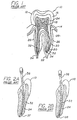
- the structure of a typical tooth 10 is shown in FIG. 1.
- the tooth has a crown 12 which extends above the gums 14 and is covered by enamel 16.
- At the heart: of the tooth is the relatively soft living pulp 18 which includes blood vessels 20 and nerves 22.
- a hard substance called dentin 24 surrounds the pulp.
- the tooth also has one or more roots 26 below the gums that fit into sockets in the jawbone 28.
- Each root is covered by a sensitive, bone like material called the cementum 30.
- Within each root is a root canal 32.
- the root canal's structure may have dramatic curvatures and other complex microstructures at almost any position within the root.
- At the end or apex 34 of the root canal is a small opening, also called the apical foramen, through which the tooth's blood vessels and nerves enter into the root canal.
- each root canal must be thoroughly cleaned eliminating tissue remnants, bacteria and antigenic inflammatory chemicals. Inadequate cleaning of the root canal may lead to short-term treatment failure, as well as long-term problems such as persistent inflammation and/or infection. Inadequate sealing of the apex 34 may allow contaminates to enter the root canal which may lead to persistent problems with or even failure of the tooth's restoration. The reintroduction of irritants and the slow dissemination of pathogenic substances through an unsealed opening exit is the most common cause of long-term endodontic failures.
- the root canal 32 must be shaped to allow controlled total filling of the root canal in all dimensions. Since a root canal frequently has an irregular structure, the shaping of the root canal must be carefully performed. As shown in FIGS. 2A and 2B, typical endodontic instruments, such as files 36 and the like, are much harder than the tooth's dentin 24 and tend to go in straight paths when used incorrectly. Such misuse of an endodontic file tends to cause blockages, ledges, via folsas 37, and perforations 38, all of which tend to decrease the chances of a successful tooth restoration. Also, incorrect use of a file may lead to overinstrumentation wherein too much healthy dentin is removed from the tooth which also tends to decrease the chances of a successful restoration.
- the opening at the apex 34 of each root canal must be precisely located and prepared for sealing.
- the location and preparation of the opening greatly determines the effectiveness of the apical seal.
- the proper preparation of the root canal 32 and location of the apex 34 typically requires a preoperative radiograph to gain insight into the size, shape and location of the root canal.
- the apical third of the root canal is obscured by the jawbone and tends to disappears from view on an x-ray image.
- the lack of a clear x-ray image of the apical third of the root canal adds to the uncertainty of the root canal's structure and the ultimate success of the restoration since this region of the root canal is where usually most of the root canals structural complexities are found.
- Other methods for determining the length of the tooth such as radiographs, tactile sense, and electronic apex detectors are not always able to precisely detect the location of the opening at the root canal's apex.
- the present invention is embodied in an apparatus for sealing and restoring a tooth's root canal.
- the apparatus includes a plunger, a long hollow tube and an optical fiber.
- the plunger forces a light cure restorative through the tube to the apex of the root canal.
- Light is delivered through the optical fiber to activate and cure the light cure restorative, thus sealing the apex of the root canal.
- the apparatus can be adapted to fill the sealed root canal with a light cure restorative.
- the entire root canal may be cleaned prepared and filled using the apparatus of the present invention.
- the crown of the tooth is opened and the pulp removed.
- the entrance at the root canal is located using induced fluorescence spectroscopy.
- root canal is cleaned and shaped. Induced fluorescence spectroscopy is used to determine whether all the infected dentin has been removed, to determine the shape of the root canal, and to prevent damaging and perforating the root canal.
- the apex is located using induced fluorescence spectroscopy and prepared. A light cure restorative is placed in the opening at the apex and activated with light. After the root canal is sealed, the remainder of the root canal is filled with light cure restorative.
- FIG. 4 shows an apparatus not claimed in the present invention, for determining the composition and anatomical boundaries of the root canal 32 of a tooth 10.
- the light source 42' a suitable HeCd low power laser, directs the excitation light 44' having a wavelength of 442 nanometers towards a suitable dichroic mirror 66.
- the dichroic mirror preferably but not necessarily one supplied by CVI of New Mexico, exhibits high reflectance at 442 nanometers and high transmittance at 500 nanometers.
- the dichroic mirror reflects the excitation light towards a first lens 68.
- the first lens 68 focuses the excitation light 44' into the end of an optical fiber 46' and also collimates the collected return light 48' that is emitted from the optical fiber.
- the optical fiber has a 400 micrometer core diameter.
- the distal end of the optical fiber scans the root canal 32 by directing the excitation light in the root canal. The same distal end also collects the return light 48' from the root canal..
- the return light passes from the fiber through the first lens, the ultraviolet mirror 66 and a long pass optical filter 70.
- the long pass optical filter has a cutoff wavelength of 325-345 nanometers to filter scattered or reflected excitation light from the return light.
- the fluorescent light is focused into a second optical fiber 72 by a second lens 74.
- the second optical fiber transmits the return light to the entrance of a spectrograph 50'.
- a suitable long pass filter such as the Schott GG475 filter, which further excludes any reflected excitation light from the return light.
- the filter is a slit having a slit width of 50 micrometers.
- the slit is followed by a diffraction grating having 100 grates per millimeter that resolves the return light along an axis.
- a detector 51 preferably a 1024 element linear device array detector (EG&G 1422G). Each element of the detector array corresponds to a spectral wavelength band of the return light.
- the detector array provides an analog signal that is converted into a digital signal for analysis and processing by an optical multichannel analyzer 52'.
- the digital signal contains data representing the intensity of light received for each of the spectral wavelengths.
- the data may also be displayed on the screen of the optical-multichannel analyzer 52' or saved on a data disk.
- a suitable system which includes both a detector and a multichannel analyzer is an OMA® 4 available from EG&G Princeton Applied Research of Princeton, New Jersey.
- the ratio of the light intensity collected in the several spectral wavelength bands or regions is calculated as discussed above. Using the calculated ratio, the intensity of light within a peak wavelength band is analyzed with the intensity of light with other spectral wavelength bands to identify the portion of the tooth within the root canal thus determining the anatomical boundaries of the tooth.
- the senor 50 may include an aberration corrected wavelength division multiplexer (WDM) and a 512 x 512 pixel charged-coupled device (CCD) array.
- WDM wavelength division multiplexer
- CCD charged-coupled device
- the fiber 46 which transmits and couples the return light into an f/2, 15 centimeter focal length aberration corrected WDM and the 512 x 512 pixel CCD array.
- the WDM's grating will be set at a fixed angle covering a 350 nanometer (300-650 nanometers) spectral range.
- the light exposure (light intensity x exposure time) for each pixel is digitized on a linear scale from 0 to 2 14 (16,384).
- the array may be liquid nitrogen cooled array which results in a substantial reduction of background noise signals.
- the average noise signal may be subtracted from the fluorescence signal from each detector element of the array.
- a suitable sensor is the 1530-CUV cryogenically cooled CCD detector available from EG&G Princeton Applied Research of Princeton, New Jersey.
- the senor 50 may include a photodetector (PD) array having a built-in thermo-electric cooler (TEC).
- TEC thermo-electric cooler
- the TEC cooled array detector operates with lower noise levels than room temperature array detectors.
- a suitable TEC cooled array is the 1530-PUV thermoelectrically cooled CCD detector available from EG&G Princeton Applied Research of Princeton, New Jersey.
- the processor 52' may include an artificial neural network as shown in FIG. 10. 5
- the artificial neural network consists of layers of interconnected processors (neurons) 106.
- the spectral data from the sensor 50' is input at the input neuron layer 108.
- each of the wavelength bands discussed is divided into 10 smaller bands or windows.
- the input neuron layer has sufficient inputs to receive the data for each wavelength band of interest.
- the neural network performs a nonlinear transformation on the input data and produces its result at the output neuron layer 110.
- Neural network has great flexibility in that it can be taught to transform the spectral data (input neuron layer) into an output (output neuron layer) that automatically and uniquely identifies the components of the tooth with relatively very high sensitivity (one to two orders higher than the conventional detection limit), high speed (a fraction of a second for identifying one spectrum), and high reliability (confidence level being indicated by neural network output).
- the software implementing the neuron network is preferably the substance identification "Neural Network" software package from Physical Optics Corporation of Torrance, California.
- the neural network operations and decision making may be performed on an IBM compatible personal computer.
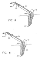
- the apex sealing apparatus 96 includes a plunger 98, a tube 100 and an optical fiber 102.
- the tube and the optical fiber extend to the apex of the root canal.
- the plunger is used to force light cure restorative through the tube.
- the light cure restorative is deposited at the apex of the root canal.
- the optical fiber delivers light to the apex to activate the light cure restorative.
- the entire root canal 32 is filled with light cure restorative as shown in FIG. 6.
- the filling instrument 104 is shown in FIG. 7 and is similar in construction to the apex sealing apparatus 96, but the tube 100' is not required to extend completely to the apex of the tooth 10.
- the fiber-optic induced fluorescence system is also suitable for detection of whether the light cure restorative 106 has actually cured. As shown in FIGS. 8 and 9, the fluorescence signal received from the light cure restorative, such as Silex Plus 3M®, before it is light activated 108 is much larger than the signal received after the restorative is activated by blue light and the compound polymerizes 110. This intensity decrease in a predetermined wavelength range, such as 500 to 540 nanometers, provides a feedback mechanism to control the root canal sealing and filling process and ensure that the sealing compound is properly cured. The curing process typically takes 1 to 5 minutes after the compound has been light activated.
- a wide variety of fibers can be used in the present invention.
- the ultraviolet and visible light is readily transmitted through polymethylmethacrylate (PMMA0), polystyrene (PS) and silica-core fibers coated with silica, plastic clad silica and metal coated silica.
- Near-infrared light is readily transmitted through silica fibers.
- Mid-infrared (Tm:YAG,Ho:YAG) light is readily transmitted through low OH anhydroguide G Silica fiber.
- Erbium YAG or Er:YSGG (3,100 nanometers) light is readily transmitted through a zirconium fluoride fiber, however, flour is toxic.
- the fiber-optic root canal tools discussed above may also be used to supplement conventional endodontic techniques of pre-procedure radiographs, tactile perception, average tooth length charts, etc.
- the dentist can choose the extent to which the fiber-optic tools are utilized.
- the endodontic tools discussed above tend to reduce the number of x-rays otherwise needed and used in conjunction with conventional instrument methods according to the skill and resources of the individual dentist.
- the endodontic tools clean and prepare the canal, thereby tending to reduce via folsas, and to minimize the dangers of broken instruments.
- the tools can establish the working length of the tooth, and locate the apex and seal the apex using light cure restoratives and/or high heat generated by light and fill the root canal with light cure restoratives.
- the tools also can eliminate pulp and pulp stones, and can cut, widen, and coagulate using infrared lasers through these same fiber-optic headpieces.
- the endodontic tools discussed above provide relatively instantaneous determination of the composition of the root canal without the processing delays associated with x-rays, etc.
Abstract
Description
Claims (2)
- Apparatus for sealing the apex (34) of a root canal (32) with a light cure restorative (106), comprising:a long hollow tube (100) sized to fit within the root canal (32) and to extend to the apex of the root canal (32);a plunger (98) for forcing the light cure restorative (106) through the tube (100) and into the apex (34) of the root canal (32); andan optical fiber (46; 88; 102) sized to extend to the apex of the root canal (32) for delivering light to the apex (34) of the root canal (32) to cure the light cure restorative (106).
- Apparatus for filling a root canal (32) with a light cure restorative (106), comprising:a long hollow tube (100') sized to fit within the root canal (32); anda plunger (98') for forcing a light cure restorative (106) through the tube (100) and into the root canal (32); andan optical fiber (46; 88; 102') for delivering light inside the root canal (32) to cure the light cure polymer (106).
Applications Claiming Priority (3)
| Application Number | Priority Date | Filing Date | Title |
|---|---|---|---|
| US129408 | 1993-09-30 | ||
| US08/129,408 US5503559A (en) | 1993-09-30 | 1993-09-30 | Fiber-optic endodontic apparatus and method |
| EP94930496A EP0720452B1 (en) | 1993-09-30 | 1994-09-28 | Fiber-optic endodontic apparatus |
Related Parent Applications (2)
| Application Number | Title | Priority Date | Filing Date |
|---|---|---|---|
| EP94930496A Division EP0720452B1 (en) | 1993-09-30 | 1994-09-28 | Fiber-optic endodontic apparatus |
| EP94930496.8 Division | 1995-04-06 |
Publications (2)
| Publication Number | Publication Date |
|---|---|
| EP0830852A1 EP0830852A1 (en) | 1998-03-25 |
| EP0830852B1 true EP0830852B1 (en) | 2002-06-05 |
Family
ID=22439799
Family Applications (3)
| Application Number | Title | Priority Date | Filing Date |
|---|---|---|---|
| EP94930496A Expired - Lifetime EP0720452B1 (en) | 1993-09-30 | 1994-09-28 | Fiber-optic endodontic apparatus |
| EP97120756A Expired - Lifetime EP0830852B1 (en) | 1993-09-30 | 1994-09-28 | Fiber-optic endodontic apparatus |
| EP97120755A Expired - Lifetime EP0830851B1 (en) | 1993-09-30 | 1994-09-28 | Fiber-optic endodontic apparatus |
Family Applications Before (1)
| Application Number | Title | Priority Date | Filing Date |
|---|---|---|---|
| EP94930496A Expired - Lifetime EP0720452B1 (en) | 1993-09-30 | 1994-09-28 | Fiber-optic endodontic apparatus |
Family Applications After (1)
| Application Number | Title | Priority Date | Filing Date |
|---|---|---|---|
| EP97120755A Expired - Lifetime EP0830851B1 (en) | 1993-09-30 | 1994-09-28 | Fiber-optic endodontic apparatus |
Country Status (6)
| Country | Link |
|---|---|
| US (1) | US5503559A (en) |
| EP (3) | EP0720452B1 (en) |
| JP (1) | JPH09505213A (en) |
| AT (3) | ATE170389T1 (en) |
| DE (3) | DE69413047T2 (en) |
| WO (1) | WO1995008962A1 (en) |
Cited By (5)
| Publication number | Priority date | Publication date | Assignee | Title |
|---|---|---|---|---|
| US7989839B2 (en) | 2002-08-23 | 2011-08-02 | Koninklijke Philips Electronics, N.V. | Method and apparatus for using light emitting diodes |
| US8047686B2 (en) | 2006-09-01 | 2011-11-01 | Dahm Jonathan S | Multiple light-emitting element heat pipe assembly |
| US8096691B2 (en) | 1997-09-25 | 2012-01-17 | Koninklijke Philips Electronics N V | Optical irradiation device |
| US9066777B2 (en) | 2009-04-02 | 2015-06-30 | Kerr Corporation | Curing light device |
| US9726435B2 (en) | 2002-07-25 | 2017-08-08 | Jonathan S. Dahm | Method and apparatus for using light emitting diodes for curing |
Families Citing this family (83)
| Publication number | Priority date | Publication date | Assignee | Title |
|---|---|---|---|---|
| EP0780103A3 (en) * | 1995-12-22 | 1997-12-03 | Heraeus Kulzer GmbH | Irradiation apparatus |
| US5713894A (en) * | 1996-02-27 | 1998-02-03 | Murphy-Chutorian; Douglas | Combined mechanical/optical system for transmyocardial revascularization |
| JPH1097166A (en) * | 1996-09-20 | 1998-04-14 | Fuji Xerox Co Ltd | Cleaning device |
| TW346391B (en) * | 1996-09-20 | 1998-12-01 | Kuraray Co | Method of polymerizing photo-polymerizable composition for dental use and dental light-curing apparatus for use therewith |
| US6119031A (en) * | 1996-11-21 | 2000-09-12 | Boston Scientific Corporation | Miniature spectrometer |
| US5918190A (en) | 1996-12-31 | 1999-06-29 | Ontario Cattlemen's Association | Software controlled meat probe for use in determining meat tenderness |
| JP3638191B2 (en) * | 1997-01-31 | 2005-04-13 | 信司 國分 | Medical laser handpiece |
| US6200134B1 (en) | 1998-01-20 | 2001-03-13 | Kerr Corporation | Apparatus and method for curing materials with radiation |
| US6349160B2 (en) | 1998-07-24 | 2002-02-19 | Aurora Biosciences Corporation | Detector and screening device for ion channels |
| US6608671B2 (en) | 1998-07-17 | 2003-08-19 | Vertex Pharmaceuticals (San Diego) Llc | Detector and screening device for ion channels |
| US6525819B1 (en) | 1998-09-02 | 2003-02-25 | Pocketspec Technologies Inc. | Colorimeter for dental applications |
| US6377842B1 (en) | 1998-09-22 | 2002-04-23 | Aurora Optics, Inc. | Method for quantitative measurement of fluorescent and phosphorescent drugs within tissue utilizing a fiber optic probe |
| NZ515203A (en) * | 1999-04-16 | 2004-02-27 | Denfotex Ltd | Method and apparatus for treating dental caries |
| MXPA01012488A (en) * | 1999-06-04 | 2003-09-10 | Denfotex Ltd | Method and apparatus for filling a dental root canal. |
| US6381301B1 (en) | 1999-12-01 | 2002-04-30 | Ronald E. Massie | Dental and orthopedic densitometry modeling system and method |
| US8073101B2 (en) * | 1999-12-01 | 2011-12-06 | Massie Ronald E | Digital modality modeling for medical and dental applications |
| US8126112B2 (en) * | 1999-12-01 | 2012-02-28 | Massie Ronald E | Osseo classification system and method |
| US6944262B2 (en) * | 1999-12-01 | 2005-09-13 | Massie Ronald E | Dental and orthopedic densitometry modeling system and method |
| FR2825260B1 (en) * | 2001-06-01 | 2004-08-20 | Centre Nat Rech Scient | METHOD AND DEVICE FOR DETECTION OF DENTAL CARIES |
| US7125254B2 (en) * | 2001-12-28 | 2006-10-24 | Randall Rex Calvert | Apparatus and method for root canal obturation |
| US20090047634A1 (en) | 2001-12-28 | 2009-02-19 | Randall Rex Calvert | Apparatus and method for root canal obturation |
| CA2385527A1 (en) * | 2002-05-09 | 2003-11-09 | Neks Recherche & Developpement Inc. | Device and method to detect dental root canal apical foramina and other structures |
| EP1531629A4 (en) | 2002-07-26 | 2006-05-17 | Olympus Corp | Image processing system |
| CN101259010B (en) * | 2002-07-26 | 2010-08-25 | 奥林巴斯株式会社 | Image processing system |
| US7172562B2 (en) * | 2002-11-22 | 2007-02-06 | Mckinley Laurence M | System, method and apparatus for locating, measuring and evaluating the enlargement of a foramen |
| CN100500093C (en) | 2003-01-14 | 2009-06-17 | 株式会社森田制作所 | Diagnostic camera |
| US7470124B2 (en) * | 2003-05-08 | 2008-12-30 | Nomir Medical Technologies, Inc. | Instrument for delivery of optical energy to the dental root canal system for hidden bacterial and live biofilm thermolysis |
| US20070072153A1 (en) * | 2003-07-09 | 2007-03-29 | Yossi Gross | Photo-sterilization |
| WO2005071372A1 (en) * | 2004-01-23 | 2005-08-04 | Olympus Corporation | Image processing system and camera |
| DE102004024494B4 (en) * | 2004-05-16 | 2019-10-17 | Dürr Dental SE | Medical camera |
| US7270543B2 (en) * | 2004-06-29 | 2007-09-18 | Therametric Technologies, Inc. | Handpiece for caries detection |
| CA2575292A1 (en) * | 2004-07-16 | 2006-02-23 | Joyces A. Osborn | Tooth whitening lens with bite plate |
| DE202004019105U1 (en) * | 2004-12-10 | 2005-02-24 | Stryker Trauma Gmbh | Device for clearing bone cavities |
| TWI266635B (en) * | 2004-12-27 | 2006-11-21 | Univ Nat Taiwan | Fiber-optic sensing system for measuring curvature |
| DE102005019386B4 (en) * | 2005-04-26 | 2010-07-29 | Ivoclar Vivadent Ag | Apparatus for polymerizing polymerizable dental material and method for determining the degree of polymerization |
| US20060252005A1 (en) * | 2005-05-06 | 2006-11-09 | Feinbloom Richard E | Apparatus for providing radiation at multiple wavelengths and method of operating same |
| US20100047733A1 (en) * | 2005-07-12 | 2010-02-25 | Sialo-Lite Ltd. | Device, system and method for procedures associated with the intra-oral cavity |
| IL169641A0 (en) * | 2005-07-12 | 2009-02-11 | Sialo Lite Ltd | Device and system for root canal treatment |
| WO2011092681A1 (en) | 2010-01-26 | 2011-08-04 | Sialo-Lite Ltd. | Dental implants, devices and methods associated with dental implantation procedures |
| US10835355B2 (en) | 2006-04-20 | 2020-11-17 | Sonendo, Inc. | Apparatus and methods for treating root canals of teeth |
| EP2015698B1 (en) | 2006-04-20 | 2017-11-15 | Sonendo, Inc. | Apparatus for treating root canals of teeth |
| US7980854B2 (en) | 2006-08-24 | 2011-07-19 | Medical Dental Advanced Technologies Group, L.L.C. | Dental and medical treatments and procedures |
| US8360771B2 (en) * | 2006-12-28 | 2013-01-29 | Therametric Technologies, Inc. | Handpiece for detection of dental demineralization |
| ATE548157T1 (en) * | 2007-06-06 | 2012-03-15 | No Screw Ltd | FASTENING MECHANISM |
| US8002544B2 (en) * | 2007-06-19 | 2011-08-23 | Biolase Technology, Inc. | Fluid controllable laser endodontic cleaning and disinfecting system |
| DE102007047068A1 (en) * | 2007-10-01 | 2009-04-02 | Ferton Holding S.A. | Device for detecting bacterial infestation in the root canal of teeth |
| DE102008011013B4 (en) * | 2008-02-25 | 2014-11-13 | Mevitec Gmbh | Method and device for complex metabolic analysis |
| US20090214089A1 (en) * | 2008-02-27 | 2009-08-27 | Therametric Technologies, Inc. | System and Method for Data Analysis And Capture |
| US9072572B2 (en) | 2009-04-02 | 2015-07-07 | Kerr Corporation | Dental light device |
| JP5828176B2 (en) * | 2009-09-09 | 2015-12-02 | 国立大学法人大阪大学 | Dental equipment |
| US9492244B2 (en) | 2009-11-13 | 2016-11-15 | Sonendo, Inc. | Liquid jet apparatus and methods for dental treatments |
| CN103347462B (en) | 2010-10-21 | 2017-05-10 | 索南多股份有限公司 | Apparatus, method, and composition for endodontic treatment |
| GB201114117D0 (en) | 2011-08-17 | 2011-10-05 | King's College London | Endodontic imaging |
| DE102012002086A1 (en) * | 2012-02-06 | 2013-08-08 | Carl Zeiss Meditec Ag | A method of examining biological tissue and devices for examining and treating the tissue |
| IN2014DN08727A (en) | 2012-03-22 | 2015-05-22 | Sonendo Inc | |
| US10631962B2 (en) | 2012-04-13 | 2020-04-28 | Sonendo, Inc. | Apparatus and methods for cleaning teeth and gingival pockets |
| US10363120B2 (en) | 2012-12-20 | 2019-07-30 | Sonendo, Inc. | Apparatus and methods for cleaning teeth and root canals |
| EP3572036B1 (en) | 2012-12-20 | 2021-05-26 | Sonendo, Inc. | Apparatus for cleaning teeth and root canals |
| KR101456101B1 (en) * | 2013-03-15 | 2014-11-04 | 배건택 | Equipment for treating periodontal disease |
| KR101456100B1 (en) * | 2013-03-15 | 2014-11-04 | 배건택 | Equipment for treating periodontal disease with replacible tip |
| DE102013006453B4 (en) | 2013-04-03 | 2020-09-10 | Festo Se & Co. Kg | Fluid power device and process for its manufacture |
| CA2910809A1 (en) | 2013-05-01 | 2014-11-06 | Sonendo, Inc. | Apparatus and methods for treating teeth |
| EP3013277B1 (en) | 2013-06-26 | 2023-07-19 | Sonendo, Inc. | Apparatus and methods for filling teeth and root canals |
| DE102013226777B4 (en) * | 2013-12-19 | 2023-01-12 | Sirona Dental Systems Gmbh | Observation unit for detecting fluorescence and a device for detecting caries |
| JP2017506947A (en) * | 2014-02-06 | 2017-03-16 | デンツプライ シロナ インコーポレーテッド | Examination of root and its endodontic space |
| RU2567605C1 (en) * | 2014-06-10 | 2015-11-10 | Государственное бюджетное образовательное учреждение высшего профессионального образования "Дальневосточный государственный медицинский университет" Министерства здравоохранения Российской Федерации (ГБОУ ВПО "ДВГМУ" Минздрава России) | Method of atromatic pre-obturation sanitation of dental root canal system |
| US10543060B2 (en) | 2015-12-03 | 2020-01-28 | Ormco Corporation | Fluted endodontic file |
| RU168454U1 (en) * | 2015-12-28 | 2017-02-03 | Анна Викторовна Ларинская | Endodontic apparatus for final pre-obstructive sanitation (sterilization) of the root canal system |
| US10806544B2 (en) | 2016-04-04 | 2020-10-20 | Sonendo, Inc. | Systems and methods for removing foreign objects from root canals |
| EP3439579A4 (en) * | 2016-04-05 | 2019-11-27 | Syact Llp | Synergistic ultrasonic, sonic or electric energy and light transmitting probe for disinfection of root canals during an endodontic procedure |
| US10321975B2 (en) | 2016-05-26 | 2019-06-18 | Ormco Corporation | Root canal debridement effectiveness device and method |
| WO2018009864A1 (en) * | 2016-07-07 | 2018-01-11 | University Of Iowa Research Foundation | Light based dental treatment device |
| WO2018011680A1 (en) | 2016-07-11 | 2018-01-18 | Ecole Polytechnique Federale De Lausanne (Epfl) | Curable filler material for tubular structures |
| WO2018081180A2 (en) * | 2016-10-24 | 2018-05-03 | Dentsply Sirona Inc. | Endodontic system and instrument for irrigation and disinfection of a tooth root canal |
| TWI617281B (en) | 2017-01-12 | 2018-03-11 | 財團法人工業技術研究院 | Method and system for analyzing wound status |
| WO2019055569A1 (en) * | 2017-09-12 | 2019-03-21 | Sonendo, Inc. | Optical systems and methods for examining a tooth |
| USD842474S1 (en) | 2017-10-20 | 2019-03-05 | Ormco Corporation | Endodontic file |
| WO2020087023A1 (en) * | 2018-10-26 | 2020-04-30 | Morio Kimberly Ann | Light-based dental treatment device |
| CA3123635A1 (en) * | 2018-12-21 | 2020-06-25 | Quantum Dental Technologies Inc. | Devices and methods for the intra-operative verification of oral health procedures |
| US11007292B1 (en) | 2020-05-01 | 2021-05-18 | Uv Innovators, Llc | Automatic power compensation in ultraviolet (UV) light emission device, and related methods of use, particularly suited for decontamination |
| USD997355S1 (en) | 2020-10-07 | 2023-08-29 | Sonendo, Inc. | Dental treatment instrument |
| EP3991686A1 (en) * | 2020-11-02 | 2022-05-04 | Ivoclar Vivadent AG | Method for securing a restoration piece |
| CN116503389B (en) * | 2023-06-25 | 2023-10-20 | 南京邮电大学 | Automatic detection method for external absorption of tooth root |
Family Cites Families (52)
| Publication number | Priority date | Publication date | Assignee | Title |
|---|---|---|---|---|
| US3313290A (en) * | 1963-08-14 | 1967-04-11 | Research Corp | Spectrofluorometer |
| US3590232A (en) * | 1968-03-27 | 1971-06-29 | Radioptics Inc | Annular illuminator for dental tools or the like |
| US3706612A (en) * | 1968-07-16 | 1972-12-19 | Ibm | Process for etching silicon nitride |
| GB1281054A (en) * | 1969-10-16 | 1972-07-12 | Vann Brothers Ltd | Improvements in or relating to dental handpieces |
| US3614414A (en) * | 1970-04-03 | 1971-10-19 | Kirkman Lab Inc | Work area illuminator |
| US3830222A (en) * | 1972-07-07 | 1974-08-20 | Johnson Res Foundation | Method and apparatus for observing rates of reaction of oxygen in living tissues |
| US3975098A (en) * | 1975-08-05 | 1976-08-17 | Applied Photophysics Limited | Spectrofluorimeter |
| US4184175A (en) * | 1977-02-09 | 1980-01-15 | The Procter & Gamble Company | Method of and apparatus for optically detecting anomalous subsurface structure in translucent articles |
| CH624294A5 (en) * | 1977-11-17 | 1981-07-31 | Polydent Sa | |
| US4170987A (en) * | 1977-11-28 | 1979-10-16 | California Institute Of Technology | Medical diagnosis system and method with multispectral imaging |
| US4236526A (en) * | 1978-01-31 | 1980-12-02 | Richard Patricia A | Method of screening for sickle cell disease by detection of porphyrins and porphyrin metabolites in human dentition |
| US4162405A (en) * | 1978-05-23 | 1979-07-24 | Britton Chance | Flying spot fluoro-meter for oxidized flavoprotein and reduced pyridine nucleotide |
| US4178917A (en) * | 1979-01-03 | 1979-12-18 | Shapiro Howard M | Method and system for non-invasive detection of zinc protoporphyrin in erythrocytes |
| FR2521727A2 (en) * | 1981-03-25 | 1983-08-19 | Cilas | DEVICE FOR MEASURING THE STATE OF OXYDO-REDUCTION OF A LIVING ORGAN IN SITU |
| US4412543A (en) * | 1981-04-09 | 1983-11-01 | Xanar, Inc. | Apparatus for determining the concentration of a fluorescent material in an eye |
| US4479499A (en) * | 1982-01-29 | 1984-10-30 | Alfano Robert R | Method and apparatus for detecting the presence of caries in teeth using visible light |
| US4569354A (en) * | 1982-03-22 | 1986-02-11 | Boston University | Method and apparatus for measuring natural retinal fluorescence |
| IS1279B6 (en) * | 1983-06-13 | 1987-07-07 | Fmc Corporation | Quality control method for fish, bovine, swine and poultry production |
| US4608990A (en) * | 1983-09-12 | 1986-09-02 | Elings Virgil B | Measuring skin perfusion |
| GB2156554B (en) * | 1984-03-10 | 1987-07-29 | Rediffusion Simulation Ltd | Processing system with shared data |
| US4629693A (en) * | 1984-03-27 | 1986-12-16 | Syntex (U.S.A.) Inc. | Sensitivity in fluorescence assays in icteric samples |
| JPS60209146A (en) * | 1984-03-31 | 1985-10-21 | Olympus Optical Co Ltd | Fluorescence spectrochemical analysis device |
| CN85100424B (en) * | 1985-04-01 | 1986-10-29 | 上海医疗器械研究所 | Inherent fluorescence diagnostic instrument for malignant tumor |
| US5034189A (en) * | 1985-08-27 | 1991-07-23 | The Regents Of The University Of California | Fluorescent probe for rapid measurement of analyte concentration |
| US5042494A (en) * | 1985-11-13 | 1991-08-27 | Alfano Robert R | Method and apparatus for detecting cancerous tissue using luminescence excitation spectra |
| US4930516B1 (en) * | 1985-11-13 | 1998-08-04 | Laser Diagnostic Instr Inc | Method for detecting cancerous tissue using visible native luminescence |
| US5001054A (en) * | 1986-06-26 | 1991-03-19 | Becton, Dickinson And Company | Method for monitoring glucose |
| US4981779A (en) * | 1986-06-26 | 1991-01-01 | Becton, Dickinson And Company | Apparatus for monitoring glucose |
| US4951669A (en) * | 1987-01-30 | 1990-08-28 | Minnesota Mining And Manufacturing Company | Blood parameter measurement system |
| US5093266A (en) * | 1987-02-06 | 1992-03-03 | Shiley Inc. | Sensor system |
| FR2612764B1 (en) * | 1987-03-26 | 1989-06-30 | Werly Marc | METHOD FOR SEALING A DENTAL CAVITY AND TOOL FOR IMPLEMENTING THE METHOD |
| US4818229A (en) * | 1987-04-29 | 1989-04-04 | Engler Engineering Corporation | Dental ultrasonic endodontic unit |
| US5037738A (en) * | 1987-06-03 | 1991-08-06 | Abbott Laboratories | Simultaneous assay for glucose and urea |
| US4894547A (en) * | 1987-09-28 | 1990-01-16 | Yale University | Optical method and apparatus for detecting and measuring aging, photoaging, dermal disease and pigmentation in skin |
| JPH0728874B2 (en) * | 1987-11-17 | 1995-04-05 | 住友電気工業株式会社 | Root canal sterilizer |
| DE3815743A1 (en) * | 1988-05-07 | 1989-11-16 | Zeiss Carl Fa | DEVICE FOR MEASURING AND EVALUATING NATURAL FLUORESCENCE SPECTRES OF ORGANIC TISSUE SURFACES |
| US4981138A (en) * | 1988-06-30 | 1991-01-01 | Yale University | Endoscopic fiberoptic fluorescence spectrometer |
| US5151029A (en) * | 1988-12-21 | 1992-09-29 | Endo Technic Corporation | Removing physiologic tissue from a tooth canal |
| US5092773A (en) * | 1989-01-18 | 1992-03-03 | Endo Technic Corporation | Method and apparatus for filling a tooth canal |
| US5046501A (en) * | 1989-01-18 | 1991-09-10 | Wayne State University | Atherosclerotic identification |
| SE8900612D0 (en) * | 1989-02-22 | 1989-02-22 | Jonas Johansson | TISSUE CHARACTERIZATION USING A BLOOD-FREE FLUORESCENCE CRITERIA |
| JP2790872B2 (en) * | 1989-09-28 | 1998-08-27 | マニー株式会社 | Root canal laser light irradiation probe |
| US5172693A (en) * | 1990-01-16 | 1992-12-22 | Doody Michael C | Prenatal non-invasive detection of meconium stained amniotic fluid |
| US5127405A (en) * | 1990-02-16 | 1992-07-07 | The Boc Group, Inc. | Biomedical fiber optic probe with frequency domain signal processing |
| US5074306A (en) * | 1990-02-22 | 1991-12-24 | The General Hospital Corporation | Measurement of burn depth in skin |
| US5209231A (en) * | 1990-11-02 | 1993-05-11 | University Of Connecticut | Optical glucose sensor apparatus and method |
| US5116227A (en) * | 1991-03-01 | 1992-05-26 | Endo Technic Corporation | Process for cleaning and enlarging passages |
| US5098298A (en) * | 1991-04-18 | 1992-03-24 | Johnson William B | Appliance and method of use for filling an endodontically prepared root canal |
| IL98355A (en) * | 1991-06-03 | 1995-06-29 | Itai Bab | Flexible-end irrigation probe |
| US5286193A (en) * | 1991-10-30 | 1994-02-15 | Roane James B | Endodontic gutta percha placement |
| US5217456A (en) * | 1992-02-24 | 1993-06-08 | Pdt Cardiovascular, Inc. | Device and method for intra-vascular optical radial imaging |
| US5284443A (en) * | 1992-08-28 | 1994-02-08 | Coltene/Whaledent, Inc. | Method of forming dental restorations |
-
1993
- 1993-09-30 US US08/129,408 patent/US5503559A/en not_active Expired - Fee Related
-
1994
- 1994-09-28 JP JP7510438A patent/JPH09505213A/en active Pending
- 1994-09-28 AT AT94930496T patent/ATE170389T1/en not_active IP Right Cessation
- 1994-09-28 WO PCT/US1994/010973 patent/WO1995008962A1/en active IP Right Grant
- 1994-09-28 AT AT97120755T patent/ATE216861T1/en not_active IP Right Cessation
- 1994-09-28 DE DE69413047T patent/DE69413047T2/en not_active Expired - Fee Related
- 1994-09-28 EP EP94930496A patent/EP0720452B1/en not_active Expired - Lifetime
- 1994-09-28 DE DE69430761T patent/DE69430761T2/en not_active Expired - Fee Related
- 1994-09-28 DE DE69430546T patent/DE69430546T2/en not_active Expired - Fee Related
- 1994-09-28 EP EP97120756A patent/EP0830852B1/en not_active Expired - Lifetime
- 1994-09-28 AT AT97120756T patent/ATE218306T1/en not_active IP Right Cessation
- 1994-09-28 EP EP97120755A patent/EP0830851B1/en not_active Expired - Lifetime
Cited By (5)
| Publication number | Priority date | Publication date | Assignee | Title |
|---|---|---|---|---|
| US8096691B2 (en) | 1997-09-25 | 2012-01-17 | Koninklijke Philips Electronics N V | Optical irradiation device |
| US9726435B2 (en) | 2002-07-25 | 2017-08-08 | Jonathan S. Dahm | Method and apparatus for using light emitting diodes for curing |
| US7989839B2 (en) | 2002-08-23 | 2011-08-02 | Koninklijke Philips Electronics, N.V. | Method and apparatus for using light emitting diodes |
| US8047686B2 (en) | 2006-09-01 | 2011-11-01 | Dahm Jonathan S | Multiple light-emitting element heat pipe assembly |
| US9066777B2 (en) | 2009-04-02 | 2015-06-30 | Kerr Corporation | Curing light device |
Also Published As
| Publication number | Publication date |
|---|---|
| WO1995008962A1 (en) | 1995-04-06 |
| DE69413047T2 (en) | 1999-04-08 |
| EP0830851B1 (en) | 2002-05-02 |
| EP0830852A1 (en) | 1998-03-25 |
| US5503559A (en) | 1996-04-02 |
| JPH09505213A (en) | 1997-05-27 |
| EP0720452B1 (en) | 1998-09-02 |
| EP0830851A1 (en) | 1998-03-25 |
| DE69430761D1 (en) | 2002-07-11 |
| DE69430546D1 (en) | 2002-06-06 |
| DE69413047D1 (en) | 1998-10-08 |
| ATE216861T1 (en) | 2002-05-15 |
| ATE218306T1 (en) | 2002-06-15 |
| ATE170389T1 (en) | 1998-09-15 |
| DE69430761T2 (en) | 2003-03-06 |
| EP0720452A1 (en) | 1996-07-10 |
| DE69430546T2 (en) | 2002-12-19 |
Similar Documents
| Publication | Publication Date | Title |
|---|---|---|
| EP0830852B1 (en) | Fiber-optic endodontic apparatus | |
| US6135774A (en) | Diagnosis and treatment device for teeth | |
| Angmar-Månsson et al. | Quantitative light-induced fluorescence (QLF): a method for assessment of incipient caries lesions | |
| Staninec et al. | Non‐destructive clinical assessment of occlusal caries lesions using near‐IR imaging methods | |
| US5616141A (en) | Laser system for use in dental procedures | |
| US20050181333A1 (en) | System and method for detecting dental caries | |
| MXPA03008575A (en) | System and method for detection and removal of dental tartar. | |
| Al‐Karadaghi et al. | The effect of bleaching gel and (940 nm and 980 nm) diode lasers photoactivation on intrapulpal temperature and teeth whitening efficiency | |
| Ghodasra et al. | Dental Caries Diagnostic Testing | |
| WO2010136776A1 (en) | Approximal imaging device | |
| Gomes et al. | Optical coherence tomography in Dentistry: scientific developments to clinical applications | |
| Lalla et al. | Does luminosity and smear layer influence 810 nm laser energy transmission through human dentine? | |
| Pelloso et al. | Chemical analysis of irradiated root dentin and its interaction with resin cements | |
| Vari et al. | Detection of dental tissues using fiberoptic sensor | |
| US20230225842A1 (en) | Dental hand-held device for curing material and stimulating fluorescence | |
| JP2023553669A (en) | Distance detection from probe to tooth pulp | |
| Pham et al. | A combination of near-infrared and fluorescence techniques for detecting early tooth lesions | |
| CA2483259C (en) | System and method for detecting dental caries | |
| US20050175967A1 (en) | Detecting dental apical foramina | |
| CA2485247A1 (en) | Detecting dental apical foramina | |
| Girkin et al. | Overview of Optical Imaging Methods Used in Dentistry |
Legal Events
| Date | Code | Title | Description |
|---|---|---|---|
| PUAI | Public reference made under article 153(3) epc to a published international application that has entered the european phase |
Free format text: ORIGINAL CODE: 0009012 |
|
| 17P | Request for examination filed |
Effective date: 19971126 |
|
| AC | Divisional application: reference to earlier application |
Ref document number: 720452 Country of ref document: EP |
|
| AK | Designated contracting states |
Kind code of ref document: A1 Designated state(s): AT CH DE FR GB IT LI NL SE |
|
| RIN1 | Information on inventor provided before grant (corrected) |
Inventor name: VARI, SANDOR G. DR. |
|
| 17Q | First examination report despatched |
Effective date: 20000204 |
|
| RTI1 | Title (correction) |
Free format text: FIBER-OPTIC ENDODONTIC APPARATUS |
|
| RTI1 | Title (correction) |
Free format text: FIBER-OPTIC ENDODONTIC APPARATUS |
|
| RIN1 | Information on inventor provided before grant (corrected) |
Inventor name: VARI, SANDOR G. DR. |
|
| RTI1 | Title (correction) |
Free format text: FIBER-OPTIC ENDODONTIC APPARATUS |
|
| GRAG | Despatch of communication of intention to grant |
Free format text: ORIGINAL CODE: EPIDOS AGRA |
|
| GRAG | Despatch of communication of intention to grant |
Free format text: ORIGINAL CODE: EPIDOS AGRA |
|
| GRAH | Despatch of communication of intention to grant a patent |
Free format text: ORIGINAL CODE: EPIDOS IGRA |
|
| GRAH | Despatch of communication of intention to grant a patent |
Free format text: ORIGINAL CODE: EPIDOS IGRA |
|
| GRAA | (expected) grant |
Free format text: ORIGINAL CODE: 0009210 |
|
| AC | Divisional application: reference to earlier application |
Ref document number: 720452 Country of ref document: EP |
|
| AK | Designated contracting states |
Kind code of ref document: B1 Designated state(s): AT CH DE FR GB IT LI NL SE |
|
| REF | Corresponds to: |
Ref document number: 218306 Country of ref document: AT Date of ref document: 20020615 Kind code of ref document: T |
|
| REG | Reference to a national code |
Ref country code: GB Ref legal event code: FG4D |
|
| REG | Reference to a national code |
Ref country code: CH Ref legal event code: EP |
|
| REF | Corresponds to: |
Ref document number: 69430761 Country of ref document: DE Date of ref document: 20020711 |
|
| REG | Reference to a national code |
Ref country code: CH Ref legal event code: NV Representative=s name: ISLER & PEDRAZZINI AG |
|
| PG25 | Lapsed in a contracting state [announced via postgrant information from national office to epo] |
Ref country code: GB Free format text: LAPSE BECAUSE OF NON-PAYMENT OF DUE FEES Effective date: 20020928 Ref country code: AT Free format text: LAPSE BECAUSE OF NON-PAYMENT OF DUE FEES Effective date: 20020928 |
|
| PG25 | Lapsed in a contracting state [announced via postgrant information from national office to epo] |
Ref country code: SE Free format text: LAPSE BECAUSE OF NON-PAYMENT OF DUE FEES Effective date: 20020929 |
|
| PG25 | Lapsed in a contracting state [announced via postgrant information from national office to epo] |
Ref country code: LI Free format text: LAPSE BECAUSE OF NON-PAYMENT OF DUE FEES Effective date: 20020930 Ref country code: CH Free format text: LAPSE BECAUSE OF NON-PAYMENT OF DUE FEES Effective date: 20020930 |
|
| ET | Fr: translation filed | ||
| PG25 | Lapsed in a contracting state [announced via postgrant information from national office to epo] |
Ref country code: NL Free format text: LAPSE BECAUSE OF NON-PAYMENT OF DUE FEES Effective date: 20030401 Ref country code: DE Free format text: LAPSE BECAUSE OF NON-PAYMENT OF DUE FEES Effective date: 20030401 |
|
| PLBE | No opposition filed within time limit |
Free format text: ORIGINAL CODE: 0009261 |
|
| STAA | Information on the status of an ep patent application or granted ep patent |
Free format text: STATUS: NO OPPOSITION FILED WITHIN TIME LIMIT |
|
| EUG | Se: european patent has lapsed | ||
| REG | Reference to a national code |
Ref country code: CH Ref legal event code: PL |
|
| GBPC | Gb: european patent ceased through non-payment of renewal fee |
Effective date: 20020928 |
|
| 26N | No opposition filed |
Effective date: 20030306 |
|
| PG25 | Lapsed in a contracting state [announced via postgrant information from national office to epo] |
Ref country code: FR Free format text: LAPSE BECAUSE OF NON-PAYMENT OF DUE FEES Effective date: 20030603 |
|
| REG | Reference to a national code |
Ref country code: FR Ref legal event code: ST |
|
| PG25 | Lapsed in a contracting state [announced via postgrant information from national office to epo] |
Ref country code: IT Free format text: LAPSE BECAUSE OF NON-PAYMENT OF DUE FEES;WARNING: LAPSES OF ITALIAN PATENTS WITH EFFECTIVE DATE BEFORE 2007 MAY HAVE OCCURRED AT ANY TIME BEFORE 2007. THE CORRECT EFFECTIVE DATE MAY BE DIFFERENT FROM THE ONE RECORDED. Effective date: 20050928 |