EP0827184A2 - Compact electrodeless fluorescent a-line lamp - Google Patents
Compact electrodeless fluorescent a-line lamp Download PDFInfo
- Publication number
- EP0827184A2 EP0827184A2 EP97306592A EP97306592A EP0827184A2 EP 0827184 A2 EP0827184 A2 EP 0827184A2 EP 97306592 A EP97306592 A EP 97306592A EP 97306592 A EP97306592 A EP 97306592A EP 0827184 A2 EP0827184 A2 EP 0827184A2
- Authority
- EP
- European Patent Office
- Prior art keywords
- ballast
- lamp
- envelope
- energy source
- excitation coil
- Prior art date
- Legal status (The legal status is an assumption and is not a legal conclusion. Google has not performed a legal analysis and makes no representation as to the accuracy of the status listed.)
- Granted
Links
Images

Classifications
-
- H—ELECTRICITY
- H05—ELECTRIC TECHNIQUES NOT OTHERWISE PROVIDED FOR
- H05B—ELECTRIC HEATING; ELECTRIC LIGHT SOURCES NOT OTHERWISE PROVIDED FOR; CIRCUIT ARRANGEMENTS FOR ELECTRIC LIGHT SOURCES, IN GENERAL
- H05B41/00—Circuit arrangements or apparatus for igniting or operating discharge lamps
- H05B41/14—Circuit arrangements
- H05B41/26—Circuit arrangements in which the lamp is fed by power derived from dc by means of a converter, e.g. by high-voltage dc
- H05B41/28—Circuit arrangements in which the lamp is fed by power derived from dc by means of a converter, e.g. by high-voltage dc using static converters
- H05B41/2806—Circuit arrangements in which the lamp is fed by power derived from dc by means of a converter, e.g. by high-voltage dc using static converters with semiconductor devices and specially adapted for lamps without electrodes in the vessel, e.g. surface discharge lamps, electrodeless discharge lamps
-
- H—ELECTRICITY
- H01—ELECTRIC ELEMENTS
- H01J—ELECTRIC DISCHARGE TUBES OR DISCHARGE LAMPS
- H01J61/00—Gas-discharge or vapour-discharge lamps
- H01J61/02—Details
- H01J61/56—One or more circuit elements structurally associated with the lamp
-
- H—ELECTRICITY
- H01—ELECTRIC ELEMENTS
- H01J—ELECTRIC DISCHARGE TUBES OR DISCHARGE LAMPS
- H01J65/00—Lamps without any electrode inside the vessel; Lamps with at least one main electrode outside the vessel
- H01J65/04—Lamps in which a gas filling is excited to luminesce by an external electromagnetic field or by external corpuscular radiation, e.g. for indicating plasma display panels
- H01J65/042—Lamps in which a gas filling is excited to luminesce by an external electromagnetic field or by external corpuscular radiation, e.g. for indicating plasma display panels by an external electromagnetic field
- H01J65/048—Lamps in which a gas filling is excited to luminesce by an external electromagnetic field or by external corpuscular radiation, e.g. for indicating plasma display panels by an external electromagnetic field the field being produced by using an excitation coil
-
- H—ELECTRICITY
- H05—ELECTRIC TECHNIQUES NOT OTHERWISE PROVIDED FOR
- H05B—ELECTRIC HEATING; ELECTRIC LIGHT SOURCES NOT OTHERWISE PROVIDED FOR; CIRCUIT ARRANGEMENTS FOR ELECTRIC LIGHT SOURCES, IN GENERAL
- H05B41/00—Circuit arrangements or apparatus for igniting or operating discharge lamps
- H05B41/02—Details
-
- Y—GENERAL TAGGING OF NEW TECHNOLOGICAL DEVELOPMENTS; GENERAL TAGGING OF CROSS-SECTIONAL TECHNOLOGIES SPANNING OVER SEVERAL SECTIONS OF THE IPC; TECHNICAL SUBJECTS COVERED BY FORMER USPC CROSS-REFERENCE ART COLLECTIONS [XRACs] AND DIGESTS
- Y02—TECHNOLOGIES OR APPLICATIONS FOR MITIGATION OR ADAPTATION AGAINST CLIMATE CHANGE
- Y02B—CLIMATE CHANGE MITIGATION TECHNOLOGIES RELATED TO BUILDINGS, e.g. HOUSING, HOUSE APPLIANCES OR RELATED END-USER APPLICATIONS
- Y02B20/00—Energy efficient lighting technologies, e.g. halogen lamps or gas discharge lamps
Definitions
- the present invention relates generally to fluorescent lamps and, more particularly, to compact electrodeless fluorescent lamps configured as A-line incandescent lamps.
- Compact fluorescent lamp products of the type having a lamp and integral ballast provide energy savings and have a longer useful life as compared to incandescent lamps of equivalent light output.
- Typical compact fluorescent lamps have tubular envelopes with one or more generally U-shaped bends. The number of bends in the lamp is a function of the desired light output and size of the lamp.
- Compact fluorescent lamps may utilize electrodes or may be electrodeless.
- the lamp is connected to an electromagnetic or electronic ballast, the latter being preferred because electronic ballasts are more compact.
- the interface between the lamp and ballast is the widest physical dimension.
- A-line The overall length of a compact fluorescent lamp and ballast exceeds that of an equivalent incandescent lamp.
- A-line The most common configuration of an incandescent lamp is referred to as A-line.
- A19, A21 and A23 There are three typical A-line bulb sizes, that is, A19, A21 and A23, with the number corresponding to the maximum diameter of the bulb in eighths of inches.
- an A21 bulb is twenty-one eighths, or 2 5 / 8, inches in maximum diameter.
- Typical power outputs of such A-line incandescent lamps is in the range from about 25 to 250 Watts.
- a compact electrodeless fluorescent lamp has an A-line configuration comprising a globular upper portion which becomes narrower toward a lower portion, terminating in a narrow end.
- the envelope has a re-entrant cavity formed therein with an excitation coil being situated within the re-entrant cavity for providing an alternating magnetic field when excited by an alternating current energy source, resulting in an arc discharge which emits ultraviolet radiation.
- the envelope has an interior phosphor coating for emitting visible radiation when excited by ultraviolet radiation.
- the narrow end of the A-line envelope is connected to a base (e.g., an Edison screw-type base).
- the alternating current energy source is electrically connected through the base, via a ballast, to the excitation coil.
- the ballast is integral with the lamp and is contained, at least partially, within the reentrant cavity.
- FIG. 1 illustrates a typical compact fluorescent lamp 10 including a gas-tight envelope 12 having multiple U-shaped tubular portions made from a translucent material.
- the envelope contains a fill comprising mercury and at least one noble gas.
- the envelope is connected to a base structure which includes a housing 14 for a ballast and a base 16, e.g., an Edison screw-type base, for connection through a fixture (not shown) to an alternating current energy source.
- the discharge tube of FIG. 1 is shown as having two U-shaped tubular sections, each U-shaped tubular section having two ends for plugging into the ballast.
- a phosphor layer 18 is applied to the inner surface of the discharge tube for converting ultraviolet radiation, which is generated by excitation of the fill, into visible light.
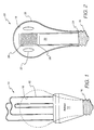
- a compact electrodeless fluorescent lamp 20 has an A-line configuration which advantageously allows for operation of the compact fluorescent lamp in a typical incandescent lamp fixture for an incandescent lamp of equivalent light output.
- the envelope for the A-line compact fluorescent lamp comprises a globular upper portion 22 which becomes narrower toward a lower portion, terminating in a narrow end 24.
- the envelope has a reentrant cavity 26 formed therein with an excitation coil 28 being situated within the re-entrant cavity for providing an alternating magnetic field when excited by an alternating current energy source, resulting in an arc discharge 27 which emits ultraviolet radiation.
- the envelope has an interior phosphor coating 18 for emitting visible radiation when excited by ultraviolet radiation.
- the narrow end 24 of the A-line envelope is connected to base 16 (e.g., an Edison screw-type base).
- base 16 e.g., an Edison screw-type base.
- the alternating current energy source is electrically connected through the base, via a ballast 30, to the excitation coil.
- the ballast is integral with the lamp and is contained, at least partially, within the re-entrant cavity.
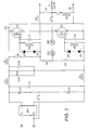
- FIG. 3 schematically illustrates a ballast suitable for operating the compact electrodeless fluorescent lamp of FIG. 2 and capable of being configured for positioning within re-entrant cavity 26.
- the illustrated ballast is a typical Class-D power amplifier with switching devices Q1 and Q2 connected together in a half-bridge configuration to be driven alternately between cutoff and saturation such that one is conducting while the other one is turned off and vice versa.
- Gate drive circuits connected to the gate of each switching device include input isolation transformer secondary windings T1A and T1B, respectively, timing capacitors C7 and C8, respectively, and Zener-diode pairs D7-D8 and D5-D6, respectively, for protecting the gates from high-voltage spikes.
- T1C is the primary winding of the input isolation transformer.
- a resonant tank circuit comprising an inductor L2 and a capacitor C6 is connected to the half-bridge at the junction between switching devices Q1 and Q2 and in parallel with switching device Q2.
- a starting circuit is shown as comprising sidacs VR1 and VR2, resistors R1 and R2, and a capacitor C3; the starting circuit provides a sufficiently high initial current for starting the lamp.
- a capacitor C9 is provided for dc blocking.
- the ballast of FIG. 3 also includes a circuit for protection against electromagnetic interference protection comprising inductors L6, L1, L3 and capacitors C1, C15, C12 and C10.
- Input bridge rectifiers for rectifying the input ac voltage are represented by block BR1; and input filter capacitors are represented as C2 and C5.
- Capacitors C2 and C5 are preferably electrolytic capacitors.
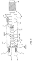
- FIGs. 4 and 5 are side views illustrating an exemplary layout of the ballast of FIG. 3 on a printed circuit board 30 wherein the ballast is positioned within the re-entrant cavity of FIG. 2.
- An exemplary re-entrant cavity has an inner diameter of 25 mm, and the width of an exemplary ballast circuit according to FIG. 3 is 22 mm, such that the ballast easily fits within the re-entrant
- electrolytic capacitors C2 and C5 are situated to extend into base 16 (FIG. 1).
- the printed circuit board is configured to support excitation coil 28 and transformer L2.
- one end of the printed circuit board is shaped to receive a core 29 around which coil 28 is wound.
- the printed circuit board is shaped to receive a core 31 of inductor L2.
- An integral lamp and ballast configuration according to the present invention i.e., with the ballast configured to fit within the re-entrant cavity of a compact electrodeless fluorescent lamp, advantageously makes the lamp even more compact and allows for use of such lamp in the fixture of an A-line incandescent lamp having equivalent light output.
- Such use for the re-entrant cavity of a compact electrodeless fluorescent lamp to provide an integral lamp and ballast configuration for a compact electrodeless fluorescent lamp should render such lamps more attractive and feasible for widespread use, thereby allowing for the widespread realization of the benefits of compact fluorescent lamps, i.e., economy and longer life.
Abstract
Description
Claims (5)
- A compact fluorescent lamp, comprising:a gas-tight, light-transmissive envelope containing a fill for sustaining an are discharge which emits ultraviolet radiation when the fill is subjected to an alternating frequency magnetic field, the envelope having a re-entrant cavity formed therein, an excitation coil being situated within the re-entrant cavity for providing the alternating magnetic field when excited by an alternating current energy source, the envelope having an interior phosphor coating for emitting visible radiation when excited by ultraviolet radiation, the envelope having an A-line configuration comprising a globular upper portion which becomes narrower toward a lower portion, terminating in a narrow end;a ballast for electrically connecting the alternating current energy source to the excitation coil and thereby operating the lamp, the ballast being integral with the lamp and contained at least partially within the re-entrant cavity; anda base connected to the narrow end of the envelope, the base being adapted for connecting the ballast to the alternating current energy source.
- The lamp of claim 1 wherein the ballast comprises a Class-D power amplifier.
- The lamp of claim 1 wherein the ballast is configured on a printed circuit board.
- The lamp of claim 3 wherein the printed circuit board is configured to support a core about which the excitation coil is wound.
- The lamp of claim 3 wherein the ballast is configured to support a core of at least one ballast inductor.
Applications Claiming Priority (2)
| Application Number | Priority Date | Filing Date | Title |
|---|---|---|---|
| US70509896A | 1996-08-28 | 1996-08-28 | |
| US705098 | 1996-08-28 |
Publications (3)
| Publication Number | Publication Date |
|---|---|
| EP0827184A2 true EP0827184A2 (en) | 1998-03-04 |
| EP0827184A3 EP0827184A3 (en) | 1998-05-20 |
| EP0827184B1 EP0827184B1 (en) | 2002-11-13 |
Family
ID=24832030
Family Applications (1)
| Application Number | Title | Priority Date | Filing Date |
|---|---|---|---|
| EP97306592A Expired - Lifetime EP0827184B1 (en) | 1996-08-28 | 1997-08-28 | Compact electrodeless fluorescent a-line lamp |
Country Status (5)
| Country | Link |
|---|---|
| US (1) | US5952792A (en) |
| EP (1) | EP0827184B1 (en) |
| JP (1) | JPH10208702A (en) |
| CN (1) | CN1123058C (en) |
| DE (1) | DE69717029T2 (en) |
Cited By (4)
| Publication number | Priority date | Publication date | Assignee | Title |
|---|---|---|---|---|
| WO2003105542A1 (en) * | 2002-06-07 | 2003-12-18 | 松下電器産業株式会社 | Electrodeless discharge lamp lighting device, light bulb type electrodeless fluorescent lamp and discharge lamp lighting device |
| WO2003105541A1 (en) * | 2002-06-07 | 2003-12-18 | 松下電器産業株式会社 | Electrodeless light bulb type fluorescent lamp and discharge lamp lighting device |
| WO2004004425A1 (en) * | 2002-06-28 | 2004-01-08 | Matsushita Electric Industrial Co.,Ltd. | Bulb-shaped electrodeless fluorescent lamp and electrodeless discharge lamp operating device |
| WO2004026005A1 (en) * | 2002-09-12 | 2004-03-25 | Matsushita Electric Industrial Co., Ltd. | Lighting device of electrodeless discharge lamp, bulb type electrodeless fluorescent lamp and lighting device of discharge lamp |
Families Citing this family (32)
| Publication number | Priority date | Publication date | Assignee | Title |
|---|---|---|---|---|
| US6548965B1 (en) * | 2000-02-16 | 2003-04-15 | Matsushita Electric Works Research And Development Labs Inc. | Electrodeless fluorescent lamp with low wall loading |
| US6348763B1 (en) | 2000-05-03 | 2002-02-19 | General Electric Company | Fluorescent lamp luminaire system |
| US7064494B2 (en) | 2001-04-12 | 2006-06-20 | Matsushita Electric Industrial Co., Ltd. | Discharge lamp operating apparatus and self-ballasted electrodeless discharge lamp |
| US7753558B2 (en) * | 2002-10-04 | 2010-07-13 | International Rectifier Corporation | Compact fluorescent lamp package |
| US7224125B2 (en) * | 2002-10-04 | 2007-05-29 | International Rectifier Corporation | Dimmable fluorescent lamp package |
| US7641364B2 (en) * | 2003-07-02 | 2010-01-05 | S. C. Johnson & Son, Inc. | Adapter for light bulbs equipped with volatile active dispenser and light emitting diodes |
| US7095176B2 (en) * | 2004-03-09 | 2006-08-22 | Lynn Judd B | Miniature tubular gas discharge lamp and method of manufacture |
| CN101065822B (en) * | 2004-11-25 | 2012-01-25 | 皇家飞利浦电子股份有限公司 | Combination of lamp and ballast with optional integrated cooling circuit |
| EP2421335A1 (en) * | 2010-08-18 | 2012-02-22 | Ronald Rudolph RiemVis | New design energy saving lamp |
| US8872426B2 (en) | 2012-11-26 | 2014-10-28 | Lucidity Lights, Inc. | Arrangements and methods for triac dimming of gas discharge lamps powered by electronic ballasts |
| US9129792B2 (en) | 2012-11-26 | 2015-09-08 | Lucidity Lights, Inc. | Fast start induction RF fluorescent lamp with reduced electromagnetic interference |
| US10128101B2 (en) | 2012-11-26 | 2018-11-13 | Lucidity Lights, Inc. | Dimmable induction RF fluorescent lamp with reduced electromagnetic interference |
| US9245734B2 (en) | 2012-11-26 | 2016-01-26 | Lucidity Lights, Inc. | Fast start induction RF fluorescent lamp with burst-mode dimming |
| US9524861B2 (en) | 2012-11-26 | 2016-12-20 | Lucidity Lights, Inc. | Fast start RF induction lamp |
| US9460907B2 (en) | 2012-11-26 | 2016-10-04 | Lucidity Lights, Inc. | Induction RF fluorescent lamp with load control for external dimming device |
| US9305765B2 (en) | 2012-11-26 | 2016-04-05 | Lucidity Lights, Inc. | High frequency induction lighting |
| US8941304B2 (en) | 2012-11-26 | 2015-01-27 | Lucidity Lights, Inc. | Fast start dimmable induction RF fluorescent light bulb |
| US10141179B2 (en) | 2012-11-26 | 2018-11-27 | Lucidity Lights, Inc. | Fast start RF induction lamp with metallic structure |
| US20140375203A1 (en) | 2012-11-26 | 2014-12-25 | Lucidity Lights, Inc. | Induction rf fluorescent lamp with helix mount |
| US10529551B2 (en) | 2012-11-26 | 2020-01-07 | Lucidity Lights, Inc. | Fast start fluorescent light bulb |
| US9161422B2 (en) | 2012-11-26 | 2015-10-13 | Lucidity Lights, Inc. | Electronic ballast having improved power factor and total harmonic distortion |
| CN107889333A (en) * | 2012-11-26 | 2018-04-06 | 明灯有限公司 | Induced RF fluorescent lamp |
| US9209008B2 (en) | 2012-11-26 | 2015-12-08 | Lucidity Lights, Inc. | Fast start induction RF fluorescent light bulb |
| US8698413B1 (en) | 2012-11-26 | 2014-04-15 | Lucidity Lights, Inc. | RF induction lamp with reduced electromagnetic interference |
| US9129791B2 (en) | 2012-11-26 | 2015-09-08 | Lucidity Lights, Inc. | RF coupler stabilization in an induction RF fluorescent light bulb |
| USD745982S1 (en) | 2013-07-19 | 2015-12-22 | Lucidity Lights, Inc. | Inductive lamp |
| USD745981S1 (en) | 2013-07-19 | 2015-12-22 | Lucidity Lights, Inc. | Inductive lamp |
| USD746490S1 (en) | 2013-07-19 | 2015-12-29 | Lucidity Lights, Inc. | Inductive lamp |
| USD747009S1 (en) | 2013-08-02 | 2016-01-05 | Lucidity Lights, Inc. | Inductive lamp |
| USD747507S1 (en) | 2013-08-02 | 2016-01-12 | Lucidity Lights, Inc. | Inductive lamp |
| USD854198S1 (en) | 2017-12-28 | 2019-07-16 | Lucidity Lights, Inc. | Inductive lamp |
| US10236174B1 (en) | 2017-12-28 | 2019-03-19 | Lucidity Lights, Inc. | Lumen maintenance in fluorescent lamps |
Citations (6)
| Publication number | Priority date | Publication date | Assignee | Title |
|---|---|---|---|---|
| US4119889A (en) * | 1975-08-13 | 1978-10-10 | Hollister Donald D | Method and means for improving the efficiency of light generation by an electrodeless fluorescent lamp |
| US4171503A (en) * | 1978-01-16 | 1979-10-16 | Kwon Young D | Electrodeless fluorescent lamp |
| EP0187494A1 (en) * | 1984-12-13 | 1986-07-16 | GTE Laboratories Incorporated | Dual cathode beam mode fluorescent lamp with capacitive ballast |
| US4675577A (en) * | 1985-04-15 | 1987-06-23 | Intent Patents A.G. | Electrodeless fluorescent lighting system |
| EP0447957A2 (en) * | 1990-03-19 | 1991-09-25 | Walter Holzer | Compact fluorescent lamp |
| EP0601893A1 (en) * | 1992-12-11 | 1994-06-15 | Flowil International Lighting (Holding) B.V. | Fluorescent lamp |
Family Cites Families (6)
| Publication number | Priority date | Publication date | Assignee | Title |
|---|---|---|---|---|
| US4480212A (en) * | 1982-06-14 | 1984-10-30 | Diolight Technology, Inc. | Extended life incandescent lamp with self contained diode and reflector |
| US4490649A (en) * | 1982-10-20 | 1984-12-25 | General Electric Company | Thermal baffle inside a discharge lamp |
| NL8500737A (en) * | 1985-03-14 | 1986-10-01 | Philips Nv | ELECTRESSLESS LOW PRESSURE DISCHARGE LAMP. |
| US5306986A (en) * | 1992-05-20 | 1994-04-26 | Diablo Research Corporation | Zero-voltage complementary switching high efficiency class D amplifier |
| US5504394A (en) * | 1993-03-08 | 1996-04-02 | Beacon Light Products, Inc. | Lamp bulb having integrated lighting function control circuitry and method of manufacture |
| US5723947A (en) * | 1996-12-20 | 1998-03-03 | Matsushita Electric Works Research & Development Laboratories Inc. | Electrodeless inductively-coupled fluorescent lamp with improved cavity and tubulation |
-
1997
- 1997-08-21 JP JP9224546A patent/JPH10208702A/en not_active Withdrawn
- 1997-08-28 DE DE69717029T patent/DE69717029T2/en not_active Expired - Fee Related
- 1997-08-28 CN CN97119291A patent/CN1123058C/en not_active Expired - Fee Related
- 1997-08-28 EP EP97306592A patent/EP0827184B1/en not_active Expired - Lifetime
-
1998
- 1998-06-23 US US09/114,232 patent/US5952792A/en not_active Expired - Fee Related
Patent Citations (6)
| Publication number | Priority date | Publication date | Assignee | Title |
|---|---|---|---|---|
| US4119889A (en) * | 1975-08-13 | 1978-10-10 | Hollister Donald D | Method and means for improving the efficiency of light generation by an electrodeless fluorescent lamp |
| US4171503A (en) * | 1978-01-16 | 1979-10-16 | Kwon Young D | Electrodeless fluorescent lamp |
| EP0187494A1 (en) * | 1984-12-13 | 1986-07-16 | GTE Laboratories Incorporated | Dual cathode beam mode fluorescent lamp with capacitive ballast |
| US4675577A (en) * | 1985-04-15 | 1987-06-23 | Intent Patents A.G. | Electrodeless fluorescent lighting system |
| EP0447957A2 (en) * | 1990-03-19 | 1991-09-25 | Walter Holzer | Compact fluorescent lamp |
| EP0601893A1 (en) * | 1992-12-11 | 1994-06-15 | Flowil International Lighting (Holding) B.V. | Fluorescent lamp |
Cited By (6)
| Publication number | Priority date | Publication date | Assignee | Title |
|---|---|---|---|---|
| WO2003105542A1 (en) * | 2002-06-07 | 2003-12-18 | 松下電器産業株式会社 | Electrodeless discharge lamp lighting device, light bulb type electrodeless fluorescent lamp and discharge lamp lighting device |
| WO2003105541A1 (en) * | 2002-06-07 | 2003-12-18 | 松下電器産業株式会社 | Electrodeless light bulb type fluorescent lamp and discharge lamp lighting device |
| US6977472B2 (en) | 2002-06-07 | 2005-12-20 | Matsushita Electric Industrial Co., Ltd. | Electrodeless self-ballasted fluorescent lamp and discharge lamp operating device |
| US6998792B2 (en) | 2002-06-07 | 2006-02-14 | Matsushita Electric Industrial Co., Ltd. | Electrodeless discharge lamp lighting device, light bulb type electrodeless fluorescent lamp and discharge lamp lighting device |
| WO2004004425A1 (en) * | 2002-06-28 | 2004-01-08 | Matsushita Electric Industrial Co.,Ltd. | Bulb-shaped electrodeless fluorescent lamp and electrodeless discharge lamp operating device |
| WO2004026005A1 (en) * | 2002-09-12 | 2004-03-25 | Matsushita Electric Industrial Co., Ltd. | Lighting device of electrodeless discharge lamp, bulb type electrodeless fluorescent lamp and lighting device of discharge lamp |
Also Published As
| Publication number | Publication date |
|---|---|
| US5952792A (en) | 1999-09-14 |
| CN1183633A (en) | 1998-06-03 |
| EP0827184B1 (en) | 2002-11-13 |
| JPH10208702A (en) | 1998-08-07 |
| DE69717029D1 (en) | 2002-12-19 |
| CN1123058C (en) | 2003-10-01 |
| DE69717029T2 (en) | 2003-10-09 |
| EP0827184A3 (en) | 1998-05-20 |
Similar Documents
| Publication | Publication Date | Title |
|---|---|---|
| EP0827184B1 (en) | Compact electrodeless fluorescent a-line lamp | |
| US8941304B2 (en) | Fast start dimmable induction RF fluorescent light bulb | |
| US5446350A (en) | Impedance matching circuit for an electrodeless fluorescent lamp ballast | |
| US9245734B2 (en) | Fast start induction RF fluorescent lamp with burst-mode dimming | |
| US10128101B2 (en) | Dimmable induction RF fluorescent lamp with reduced electromagnetic interference | |
| US9305765B2 (en) | High frequency induction lighting | |
| US6522084B1 (en) | Electrodeless discharge lamp operating apparatus | |
| US9524861B2 (en) | Fast start RF induction lamp | |
| US9129792B2 (en) | Fast start induction RF fluorescent lamp with reduced electromagnetic interference | |
| US20140145607A1 (en) | Dimmable high frequency induction rf fluorescent lamp | |
| US20140145601A1 (en) | Dimmable induction rf fluorescent lamp | |
| US20140145608A1 (en) | Fast start high frequency induction rf fluorescent lamp | |
| US20140145606A1 (en) | High frequency induction rf fluorescent lamp | |
| US20140145604A1 (en) | Induction rf fluorescent lamp | |
| US20140145598A1 (en) | High frequency induction rf fluorescent lamp with burst-mode dimming | |
| US20140145600A1 (en) | High frequency induction rf fluorescent lamp with reduced electromagnetic interference | |
| US20140145603A1 (en) | Induction rf fluorescent lamp with reduced electromagnetic interference | |
| US20140145605A1 (en) | High frequency induction rf fluorescent lamp with reduced electromagnetic interference | |
| US20140145602A1 (en) | Induction rf fluorescent lamp with burst-mode dimming | |
| US20140320008A1 (en) | Processor-based fast start induction rf fluorescent lamp | |
| EP2923373A1 (en) | Induction rf fluorescent lamp | |
| US20140145597A1 (en) | Processor-based induction rf fluorescent lamp | |
| US20140320009A1 (en) | Processor-based dimmable induction rf fluorescent lamp | |
| IE43936B1 (en) | Light generation by an electrodeless fluorescent lamp | |
| US20140145618A1 (en) | Dimmable induction rf fluorescent light bulb |
Legal Events
| Date | Code | Title | Description |
|---|---|---|---|
| PUAI | Public reference made under article 153(3) epc to a published international application that has entered the european phase |
Free format text: ORIGINAL CODE: 0009012 |
|
| AK | Designated contracting states |
Kind code of ref document: A2 Designated state(s): DE FR GB IT |
|
| PUAL | Search report despatched |
Free format text: ORIGINAL CODE: 0009013 |
|
| AK | Designated contracting states |
Kind code of ref document: A3 Designated state(s): AT BE CH DE DK ES FI FR GB GR IE IT LI LU MC NL PT SE |
|
| 17P | Request for examination filed |
Effective date: 19981120 |
|
| AKX | Designation fees paid |
Free format text: DE FR GB IT |
|
| RBV | Designated contracting states (corrected) |
Designated state(s): DE FR GB IT |
|
| 17Q | First examination report despatched |
Effective date: 20000925 |
|
| GRAG | Despatch of communication of intention to grant |
Free format text: ORIGINAL CODE: EPIDOS AGRA |
|
| GRAG | Despatch of communication of intention to grant |
Free format text: ORIGINAL CODE: EPIDOS AGRA |
|
| GRAH | Despatch of communication of intention to grant a patent |
Free format text: ORIGINAL CODE: EPIDOS IGRA |
|
| GRAH | Despatch of communication of intention to grant a patent |
Free format text: ORIGINAL CODE: EPIDOS IGRA |
|
| GRAA | (expected) grant |
Free format text: ORIGINAL CODE: 0009210 |
|
| AK | Designated contracting states |
Kind code of ref document: B1 Designated state(s): DE FR GB IT |
|
| REG | Reference to a national code |
Ref country code: GB Ref legal event code: FG4D |
|
| REF | Corresponds to: |
Ref document number: 69717029 Country of ref document: DE Date of ref document: 20021219 |
|
| ET | Fr: translation filed | ||
| PG25 | Lapsed in a contracting state [announced via postgrant information from national office to epo] |
Ref country code: GB Free format text: LAPSE BECAUSE OF NON-PAYMENT OF DUE FEES Effective date: 20030828 |
|
| PLBE | No opposition filed within time limit |
Free format text: ORIGINAL CODE: 0009261 |
|
| STAA | Information on the status of an ep patent application or granted ep patent |
Free format text: STATUS: NO OPPOSITION FILED WITHIN TIME LIMIT |
|
| 26N | No opposition filed |
Effective date: 20030814 |
|
| PG25 | Lapsed in a contracting state [announced via postgrant information from national office to epo] |
Ref country code: DE Free format text: LAPSE BECAUSE OF NON-PAYMENT OF DUE FEES Effective date: 20040302 |
|
| GBPC | Gb: european patent ceased through non-payment of renewal fee | ||
| PG25 | Lapsed in a contracting state [announced via postgrant information from national office to epo] |
Ref country code: FR Free format text: LAPSE BECAUSE OF NON-PAYMENT OF DUE FEES Effective date: 20040430 |
|
| REG | Reference to a national code |
Ref country code: FR Ref legal event code: ST |
|
| PG25 | Lapsed in a contracting state [announced via postgrant information from national office to epo] |
Ref country code: IT Free format text: LAPSE BECAUSE OF NON-PAYMENT OF DUE FEES Effective date: 20050828 |