EP0826986A1 - Color filter and color display apparatus - Google Patents
Color filter and color display apparatus Download PDFInfo
- Publication number
- EP0826986A1 EP0826986A1 EP96113818A EP96113818A EP0826986A1 EP 0826986 A1 EP0826986 A1 EP 0826986A1 EP 96113818 A EP96113818 A EP 96113818A EP 96113818 A EP96113818 A EP 96113818A EP 0826986 A1 EP0826986 A1 EP 0826986A1
- Authority
- EP
- European Patent Office
- Prior art keywords
- light beam
- light
- hologram
- light beams
- modulation device
- Prior art date
- Legal status (The legal status is an assumption and is not a legal conclusion. Google has not performed a legal analysis and makes no representation as to the accuracy of the status listed.)
- Withdrawn
Links
Images


Classifications
-
- H—ELECTRICITY
- H04—ELECTRIC COMMUNICATION TECHNIQUE
- H04N—PICTORIAL COMMUNICATION, e.g. TELEVISION
- H04N9/00—Details of colour television systems
- H04N9/12—Picture reproducers
- H04N9/31—Projection devices for colour picture display, e.g. using electronic spatial light modulators [ESLM]
- H04N9/3102—Projection devices for colour picture display, e.g. using electronic spatial light modulators [ESLM] using two-dimensional electronic spatial light modulators
- H04N9/3105—Projection devices for colour picture display, e.g. using electronic spatial light modulators [ESLM] using two-dimensional electronic spatial light modulators for displaying all colours simultaneously, e.g. by using two or more electronic spatial light modulators
- H04N9/3108—Projection devices for colour picture display, e.g. using electronic spatial light modulators [ESLM] using two-dimensional electronic spatial light modulators for displaying all colours simultaneously, e.g. by using two or more electronic spatial light modulators by using a single electronic spatial light modulator
-
- G—PHYSICS
- G02—OPTICS
- G02B—OPTICAL ELEMENTS, SYSTEMS OR APPARATUS
- G02B5/00—Optical elements other than lenses
- G02B5/20—Filters
- G02B5/203—Filters having holographic or diffractive elements
-
- H—ELECTRICITY
- H04—ELECTRIC COMMUNICATION TECHNIQUE
- H04N—PICTORIAL COMMUNICATION, e.g. TELEVISION
- H04N5/00—Details of television systems
- H04N5/72—Modifying the appearance of television pictures by optical filters or diffusing screens
-
- G—PHYSICS
- G02—OPTICS
- G02F—OPTICAL DEVICES OR ARRANGEMENTS FOR THE CONTROL OF LIGHT BY MODIFICATION OF THE OPTICAL PROPERTIES OF THE MEDIA OF THE ELEMENTS INVOLVED THEREIN; NON-LINEAR OPTICS; FREQUENCY-CHANGING OF LIGHT; OPTICAL LOGIC ELEMENTS; OPTICAL ANALOGUE/DIGITAL CONVERTERS
- G02F1/00—Devices or arrangements for the control of the intensity, colour, phase, polarisation or direction of light arriving from an independent light source, e.g. switching, gating or modulating; Non-linear optics
- G02F1/01—Devices or arrangements for the control of the intensity, colour, phase, polarisation or direction of light arriving from an independent light source, e.g. switching, gating or modulating; Non-linear optics for the control of the intensity, phase, polarisation or colour
- G02F1/13—Devices or arrangements for the control of the intensity, colour, phase, polarisation or direction of light arriving from an independent light source, e.g. switching, gating or modulating; Non-linear optics for the control of the intensity, phase, polarisation or colour based on liquid crystals, e.g. single liquid crystal display cells
- G02F1/133—Constructional arrangements; Operation of liquid crystal cells; Circuit arrangements
- G02F1/1333—Constructional arrangements; Manufacturing methods
- G02F1/1335—Structural association of cells with optical devices, e.g. polarisers or reflectors
- G02F1/1336—Illuminating devices
- G02F1/133621—Illuminating devices providing coloured light
Definitions
- This invention relates to a color filter which can be used for various apparatuses such as an image input unit of a camera and an image output unit of a display. This invention also relates to a color display apparatus.
- a known color filter includes a hologram and a plate having an array of primary color pixels.
- the hologram and the color pixel array plate are spaced from and parallel with each other.
- a light source applies a white light beam to the hologram.
- the white light beam is diffracted and is separated into a red light beam, a green light beam, and a blue light beam when passing through the hologram.
- the red light beam, the green light beam, and the blue light beam are focused on a red pixel, a green pixel, and a blue pixel in the color pixel array plate respectively, undergoing modulation and passing through the color pixel array plate.
- the red light beam, the green light beam, and the blue light beam which have passed through the color pixel array plate form an indicated color image.
- the red light beam, the green light beam, and the blue light beam are incident to the red pixel, the green pixel, and the blue pixel in the color pixel array plate at different angles respectively. These angles of incidence do not correspond to a right angle. Specifically, the paths of the red light beam, the green light beam, and the blue light beam tend to be considerably slant with respect to the color pixel array plate. Accordingly, the known color filter tends to be low in efficiency of use of light.
- a first aspect of this invention provides a color filter comprising a plurality of color pixels; a first hologram diffracting an incident light beam into a first diffraction-resultant light beam; and a second hologram diffracting the first diffraction-resultant light beam into a second diffraction-resultant light beam having a plurality of light beams with different wavelengths respectively, the second hologram directing the different wavelength light beams toward the color pixels respectively.
- a second aspect of this invention is based on the first aspect thereof, and provides a color filter wherein the first hologram has a diffraction efficiency independent of or slightly dependent on a wavelength of the incident light beam.
- a third aspect of this invention is based on the first aspect thereof, and provides a color filter wherein the first hologram has a plurality of different holographic patterns with diffraction efficiencies depending on a wavelength of the incident light beam.
- a fourth aspect of this invention is based on the first aspect thereof, and provides a color filter wherein the second hologram has a plurality of different holographic patterns with diffraction efficiencies depending on a wavelength of the incident light beam.
- a fifth aspect of this invention is based on the first aspect thereof, and provides a color filter further comprising means for limiting a wavelength band of the incident light beam before the incident light beam meets the first hologram.
- a sixth aspect of this invention is based on the fifth aspect thereof, and provides a color filter wherein said means comprises dichroic mirrors.
- a seventh aspect of this invention provides a color display apparatus comprising a light source emitting a light beam; first means for separating the light beam emitted from the light source into first, second, and third light beams having first, second, and third primary colors respectively; a spatial light modulation device exposed to the first, second, and third light beams generated by the first means, the spatial light modulation device modulating the first, second, and third light beams into first, second, and third modulation-resultant light beams respectively; and second means for projecting the first, second, and third modulation-resultant light beams generated by the spatial light modulation device into a color image; wherein the spatial light modulation device comprises i) first, second, and third pixels related to the first, second, and third primary colors respectively; ii) a first hologram diffracting the first, second, and third light beams generated by the first means into first, second, and third diffraction-resultant light beams respectively; and iii) a second hologram diff
- An eighth aspect of this invention is based on the seventh aspect thereof, and provides a color display apparatus wherein the first means comprises first, second, and third dichroic mirrors which reflect first, second, and third components of the light beam emitted from the light source which have the first, second, and third primary colors respectively.
- a ninth aspect of this invention provides a color display apparatus comprising a light source emitting a light beam; first means for separating the light beam emitted from the light source into first, second, and third light beams having first, second, and third primary colors respectively; a spatial light modulation device exposed to the first, second, and third light beams generated by the first means, the spatial light modulation device modulating the first, second, and third light beams into first, second, and third modulation-resultant light beams respectively; and second means for projecting the first, second, and third modulation-resultant light beams generated by the spatial light modulation device into a color image; wherein the spatial light modulation device comprises i) a first electrode being transparent and being exposed to the first, second, and third light beams generated by the first means; ii) a second electrode including first, second, and third pixel electrodes related to the first, second, and third primary colors respectively; iii) a light modulation layer extending between the first electrode and the second electrode; i
- a tenth aspect of this invention provides a color display apparatus comprising a light source emitting a light beam; a hologram diffracting the light beam emitted from the light source and thereby separating the light beam emitted from the light source into first, second, and third light beams having first, second, and third primary colors respectively; a spatial light modulation device exposed to the first, second, and third light beams generated by the hologram, the spatial light modulation device modulating the first, second, and third light beams into first, second, and third modulation-resultant light beams respectively; and first means for projecting the first, second, and third modulation-resultant light beams generated by the spatial light modulation device into a color image; wherein the spatial light modulation device comprises i) a first electrode being transparent and being exposed to the first, second, and third light beams generated by the hologram; ii) a second electrode including first, second, and third pixel electrodes related to the first, second, and third primary colors respectively; i
- An eleventh aspect of this invention is based on the ninth aspect thereof, and provides a color display apparatus wherein the third means comprises a hologram.
- a twelfth aspect of this invention is based on the ninth aspect thereof, and provides a color display apparatus wherein the third means comprises a micro lens.
- a thirteenth aspect of this invention is based on the ninth aspect thereof, and provides a color display apparatus wherein the third means comprises a micro prism.
- a fourteenth aspect of this invention provides a color display apparatus comprising a light source emitting a light beam; a spatial light modulation device exposed to the light beam emitted from the light source, the spatial light modulation device modulating the light beam emitted from the light source into a modulation-resultant light beam; and first means for projecting the modulation-resultant light beam generated by the spatial light modulation device into a color image; wherein the spatial light modulation device comprises i) a first electrode being transparent and being exposed to the first, second, and third light beams generated by the first means; ii) a second electrode including first, second, and third pixel electrodes related to the first, second, and third primary colors respectively; iii) a light modulation layer extending between the first electrode and the second electrode; iv) a hologram diffracting the light beam emitted from the light source and thereby separating the light beam emitted from the light source into first, second, and third light beams having first, second, and third primary
- a fifteenth aspect of this invention is based on the fourteenth aspect thereof, and provides a color display apparatus wherein the second means comprises a hologram.
- a sixteenth aspect of this invention is based on the fourteenth aspect thereof, and provides a color display apparatus wherein the second means comprises a micro lens.
- a seventeenth aspect of this invention is based on the fourteenth aspect thereof, and provides a color display apparatus wherein the second means comprises a micro prism.
- An eighteenth aspect of this invention is based on the fourteenth aspect thereof, and provides a color display apparatus further comprising dichroic mirrors located between the light source and the spatial light modulation device and relating the first, second, and third primary colors respectively.
- a nineteenth aspect of this invention provides a color filter comprising first, second, and third color pixels for modulating light beams having first, second, and third primary colors respectively; a first hologram diffracting an incident light beam into a first diffraction-resultant light beam; and a second hologram diffracting the first diffraction-resultant light beam into a second diffraction-resultant light beam Including first, second, and third sub light beams which have the first, second, and third primary colors respectively, the second hologram directing the first, second, and third sub light beams toward the first, second, and third color pixels respectively.
- a twentieth aspect of this invention provides a color display apparatus comprising a spatial light modulation device exposed to an incident light beam, and modulating the incident light beam into a modulation-resultant light beam; and first means for projecting the modulation-resultant light beam into a color image; wherein the spatial light modulation device comprises i) first, second, and third color pixels for modulating light beams having first, second, and third primary colors respectively; ii) a first hologram diffracting the incident light beam into a first diffraction-resultant light beam; and iii) a second hologram diffracting the first diffraction-resultant light beam into a second diffraction-resultant light beam including first, second, and third sub light beams which have the first, second, and third primary colors respectively, the second hologram directing the first, second, and third sub light beams toward the first, second, and third color pixels respectively.
- Fig. 1 is a sectional view of a spatial light modulation device according to a first embodiment of this invention.
- Fig. 2 is a diagram of a color display apparatus according to a second embodiment of this invention.
- Fig. 3 is a diagram of a color display apparatus according to a third embodiment of this invention.
- Fig. 4 is a diagram of micro lenses and pixel electrodes in a spatial light modulation device in Fig. 3.
- Fig. 5 is a sectional view of the spatial light modulation device in Fig. 3.
- Fig. 6 is a sectional view of a spatial light modulation device in a color display apparatus according to a fourth embodiment of this invention.
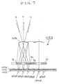
- Fig. 7 is a sectional view of a spatial light modulation device in a color display apparatus according to a fifth embodiment of this invention.
- Fig. 8 is a sectional view of a spatial light modulation device in a color display apparatus according to a sixth embodiment of this invention.
- Fig. 9 is a diagram of micro lenses in the spatial light modulation device in Fig. 8.
- Fig. 10 is a sectional view of a spatial light modulation device in a color display apparatus according to a seventh embodiment of this invention.
- Fig. 11 is a sectional view of a spatial light modulation device in a color display apparatus according to an eighth embodiment of this invention.
- Fig. 12 is a sectional view of a spatial light modulation device in a color display apparatus according to a ninth embodiment of this invention.
- Fig. 13 is a sectional view of a spatial light modulation device and hologram layers in a color display apparatus according to a tenth embodiment of this invention.
- a spatial light modulation device (a spatial light modulation element) 10 including a color filter has a glass substrate 11 on which a pixel electrode layer 12a, a liquid crystal layer 12b, and a transparent electrode layer 12c are sequentially formed in a laminated structure.
- the liquid crystal layer 12b extends between the pixel electrode layer 12a and the transparent electrode layer 12c.
- the transparent electrode layer 12c is made of, for example, ITO (indium tin oxide).
- the liquid crystal layer 12b is driven by a signal voltage applied between the pixel electrode layer 12a and the transparent electrode layer 12c.
- the pixel electrode layer 12a includes an array of independent and separate red pixel electrodes 12aR, green pixel electrodes 12aG, and blue pixel electrodes 12aB.
- the red pixel electrodes 12aR correspond to red pixels 12R respectively.
- the green pixel electrodes 12aG correspond to green pixels 12G respectively.
- the blue pixel electrodes 12aB correspond to blue pixels 12B respectively.
- Each red pixel 12R is composed of a red pixel electrode 12aR, a region of the liquid crystal layer 12b directly above the red pixel electrode 12aR, and a region of the transparent electrode layer 12c directly above the red pixel electrode 12aR.
- Each green pixel 12G is composed of a green pixel electrode 12aG, a region of the liquid crystal layer 12b directly above the green pixel electrode 12aG, and a region of the transparent electrode layer 12c directly above the green pixel electrode 12aG.
- Each blue pixel 12B is composed of a blue pixel electrode 12aB, a region of the liquid crystal layer 12b directly above the blue pixel electrode 12aB, and a region of the transparent electrode layer 12c directly above the blue pixel electrode 12aB.
- the spatial light modulation device 10 includes an array of unit pixels 12 each composed of one red pixel 12R, one green pixel 12G, and one blue pixel 12B.
- An example of the array of the unit pixels 12 is of the delta type in which a unit pixel 12 recurs along a row direction (a horizontal direction), and also recurs along a column direction (a vertical direction) at an equal phase.
- unit pixels 12 in every even-numbered row are positionally offset from unit pixels 12 in every odd-numbered row by a phase corresponding to a half of one unit pixel 12.
- the array of the unit pixels 12 may be of the stripe type.
- the spatial light modulation device 10 is of a reflection type in which the reflection of light occurs at the pixel electrode layer 12a.
- a dielectric mirror layer may be provided between the liquid crystal layer 12b and the pixel electrode layer 12a to implement the reflection of light.
- a glass layer 13 is formed on the transparent electrode layer 12c.
- a hologram 14 is formed on the glass layer 13.
- the hologram 14 has a lens function (a focusing function) by which a red light beam, a green light beam, and a blue light beam are focused on a red pixel 12R, a green pixel 12G, and a blue pixel 12B respectively.
- the hologram 14 directs the red light beam, the green light beam, and the blue light beam so that they will meet the red pixel 12R, the green pixel 12G, and the blue pixel 12B at approximately right angles respectively.
- the hologram 14 has a laminate or a superposition of sub holograms 14R, 14G, and 14B for red, green, and blue respectively.
- the red sub hologram 14R diffracts a red light beam, and focuses the red light beam on a red pixel 12R at approximately a right angle.
- the red sub hologram 14R operates on substantially only red light, and thus its diffraction efficiency depends on the wavelength of applied light.
- the green sub hologram 14G diffracts a green light beam, and focuses the green light beam on a green pixel 12G at approximately a right angle.
- the green sub hologram 14G operates on substantially only green light, and thus its diffraction efficiency depends on the wavelength of applied light.
- the blue sub hologram 14B diffracts a blue light beam, and focuses the blue light beam on a blue pixel 12B at approximately a right angle.
- the blue sub hologram 14B operates on substantially only blue light, and thus its diffraction efficiency depends on the wavelength of applied light.
- a glass layer 15 is formed on the hologram 14.
- Another hologram 16 is formed on the glass layer 15.
- the hologram 16 deflects and diffracts an incident light beam.
- the hologram 16 serves to change the direction of travel of the incident light beam.
- a glass layer 17 is formed on the hologram 16.
- the spatial light modulation device 10 operates as follows. In a region approximately directly above one unit pixel 12, a forward light beam (an incident light beam) F1 is applied from above to the upper surface of the spatial light modulation device 10 along substantially a normal direction with respect thereto. The forward light beam F1 passes through the glass layer 17 before reaching the hologram 16. The forward light beam F1 is diffracted by the hologram 16 when passing therethrough. Different-wavelength components (different color components) of the forward light beam F1 are outputted from the hologram 16 at different angles respectively. Accordingly, the hologram 16 separates the forward light beam F1 into different-color forward light beams including a red light beam, a green light beam, and a blue light beam.
- the forward red light beam, the forward green light beam, and the forward blue light beam outputted from the hologram 16 pass through the glass layer 15 before reaching the hologram 14.
- the forward red light beam is diffracted and is changed in travel direction when passing through the red sub hologram 14R.
- the forward red light beam passes through the green sub hologram 14G and the blue sub hologram 14B without being processed or changed thereby.
- the red sub hologram 14R has a lens function by which the forward red light beam is focused on a corresponding red pixel electrode 12aR.
- the forward green light beam is diffracted and is changed in travel direction when passing through the green sub hologram 14G.
- the forward green light beam passes through the red sub hologram 14R and the blue sub hologram 14B without being processed or changed thereby.
- the green sub hologram 14G has a lens function by which the forward green light beam is focused on a corresponding green pixel electrode 12aG.
- the forward blue light beam is diffracted and is changed in travel direction when passing through the blue sub hologram 14B.
- the forward blue light beam passes through the red sub hologram 14R and the green sub hologram 14G without being processed or changed thereby.
- the blue sub hologram 14B has a lens function by which the forward blue light beam is focused on a corresponding blue pixel electrode 12aB.
- the forward red light beam, the forward green light beam, and the forward blue light beam outputted from the hologram 14 pass through the glass layer 13 before reaching a corresponding red pixel 12R, a corresponding green pixel 12G, and a corresponding blue pixel 12B respectively.
- the forward red light beam successively passes through the transparent electrode 12c and the liquid crystal layer 12b before reaching the corresponding red pixel electrode 12aR.
- the forward green light beam successively passes through the transparent electrode 12c and the liquid crystal layer 12b before reaching the corresponding green pixel electrode 12aG.
- the forward blue light beam successively passes through the transparent electrode 12c and the liquid crystal layer 12b before reaching the corresponding blue pixel electrode 12aB.
- the travel direction change of the forward red light beam by the red sub hologram 14R substantially cancels the travel direction change of the forward red light beam by the hologram 16. Accordingly, the forward red light beam is incident to the corresponding red pixel 12R along approximately a normal direction with respect thereto.
- the travel direction change of the forward green light beam by the green sub hologram 14G substantially cancels the travel direction change of the forward green light beam by the hologram 16. Accordingly, the forward green light beam is incident to the corresponding green pixel 12G along approximately a normal direction with respect thereto.
- the travel direction change of the forward blue light beam by the blue sub hologram 14B substantially cancels the travel direction change of the forward blue light beam by the hologram 16.
- the forward blue light beam is incident to the corresponding blue pixel 12B along approximately a normal direction with respect thereto.
- the incidences of the forward red, green, and blue light beams to the red, green, and blue pixels 12R, 12G, and 12B along the normal directions provide a high efficiency of use of light.
- the red light beam, the green light beam, and the blue light beam are reflected at the upper surfaces of the corresponding red pixel electrode 12aR, the corresponding green pixel electrode 12aG, and the corresponding blue pixel electrode 12aB respectively. Then, the red light beam, the green light beam, and the blue light beam return along the paths substantially same as those of the forward travel thereof respectively. During the return, the red light beam, the green light beam, and the blue light beam successively pass through the liquid crystal layer 12b, the transparent electrode 12c, the glass layer 13, the hologram 14, the glass layer 15, the hologram 16, and the glass layer 17. Then, the return red light beam, the return green light beam, and the return blue light beam leave the spatial light modulation device 10 as a composite return light beam (a composite reflected light beam) F2.
- the red light beam is modulated by the liquid crystal layer 12b in response to a signal voltage applied between the corresponding red pixel electrode 12aR and the transparent electrode 12c.
- the green light beam is modulated by the liquid crystal layer 12b in response to a signal voltage applied between the corresponding green pixel electrode 12aG and the transparent electrode 12c.
- the blue light beam is modulated by the liquid crystal layer 12b in response to a signal voltage applied between the corresponding blue pixel electrode 12aB and the transparent electrode 12c. Accordingly, the return red light beam, the return green light beam, and the return blue light beam are modulation-resultant red, green, and blue light beams which form an indicated color image.
- a first example of the hologram 16 has a diffraction efficiency which is independent of or is slightly dependent on the wavelength of applied light.
- a second example of the hologram 16 has a diffraction efficiency which depends on the wavelength of applied light.
- a third example of the hologram 16 has a laminate or a superposition of a first sub hologram diffracting only red light, a second sub hologram diffracting only green light, and a third sub hologram diffracting only blue light.
- a fourth example of the hologram 16 has a diffraction efficiency which is independent of or is slightly dependent on the wavelength of applied light.
- the fourth example of the hologram 16 provides a diffraction angle which is independent of or is slightly dependent on the wavelength of applied light.
- the hologram 16 provides a diffraction angle depending on the wavelength of applied light, it is preferable to differentiate the diffraction angles provided by the hologram 14 for red light, green light, and blue light respectively.
- the hologram 16 provides a diffraction angle independent of the wavelength of applied light, it is preferable to equalize the diffraction angles provided by the hologram 14 for red light, green light, and blue light respectively.
- Each of the holograms 14 and 16 may include a plane hologram such as a Lippmann hologram.
- each of the holograms 14 and 16 may include a volume hologram such as a relief hologram, a phase hologram, or an amplitude hologram.
- the hologram 14 has a focusing function.
- a first example of the hologram 14 has a pattern of Fresnel zones.
- a second example of the hologram 14 has a pattern of concentric circles of interference fringes which are arranged at different pitches.
- a third example of the hologram 14 has a honeycomb pattern of interference fringes.
- the hologram 16 may have a focusing function.
- the hologram 14 can be of the non-focusing type.
- the glass layer 15 may be omitted.
- the hologram 16 is directly superposed on the hologram 14.
- the presence of the hologram 16 enables increased angles of incidence of the red, green, and blue light beams to the hologram 14. Accordingly, the angle of incidence of an input light beam to the spatial light modulation device 10 can be small.
- the image circle of a projection lens of the display apparatus is prevented from excessively increasing. This is advantageous in providing a high brightness, a high resolution, and a compact structure of the display apparatus.
- the spatial light modulation device 10 can be used in various apparatuses such as a liquid crystal display of a transmission type or a reflection type, or a CCD camera.
- the spatial light modulation device 10 is located at an input side of a photodetector array in a camera.
- a color display apparatus 20 includes a light source 21 emitting a forward beam F1 of white light toward a lens 22.
- the forward light beam F1 passes through the lens 22 before reaching a cold mirror 23 and being reflected thereby.
- the forward light beam F1 travels from the cold mirror 23 to a lens 24, and then passes through the lens 24.
- Infrared components are removed from the forward light beam F1 by the lens 22, the cold mirror 23, and the lens 24.
- the forward light beam F1 is made into a beam of approximately parallel rays by the lens 22, the cold mirror 23, and the lens 24.
- the parallel-light beam travels from the lens 24 to a set 25 of dichroic mirrors 25B, 25R, and 25G.
- Blue components of the parallel-light beam are reflected by the dichroic mirror 25B while green and red components of the parallel-light beam pass therethrough.
- the green and red light components which have passed through the dichroic mirror 25B meet the dichroic mirror 25R.
- the red light components are reflected by the dichroic mirror 25R while the green light components pass therethrough.
- the green light components which have passed through the dichroic mirror 25R meet the dichroic mirror 25G.
- the green light components are reflected by the dichroic mirror 25G.
- the reflecting surfaces of the dichroic mirrors 25B, 25R, and 25G are parallel to each other so that the blue light components, the red light components, and the green light components are reflected thereby at equal angles or toward parallel directions respectively.
- the reflected blue light beam, the reflected red light beam, and the reflected green light beam travel from the dichroic mirror set 25 to an effective plane 26a within a polarization beam splitter 26.
- the dichroic mirror set 25 limits the wavelength band of light by selecting blue components, red components, and green components thereof.
- the dichroic mirrors 25B, 25R, and 25G are spaced at intervals very short relative to the diameter or the width of the parallel-light beam incident to the dichroic mirror set 25.
- the optical axes of the blue light beam, the red light beam, and the green light beam emitted from the dichroic mirror set 25 are approximately coincident with each other.
- the p-polarized components of the forward blue light beam, the forward red light beam, and the forward green light beam pass through the effective plane 26a within the polarization beam splitter 26 before being incident to a spatial light modulation device 10. It is preferable that the p-polarized components of the forward blue light beam, the forward red light beam, and the forward green light beam are incident to the spatial light modulation device 10 at substantially right angles.
- the spatial light modulation device 10 is similar to that in the first embodiment.
- the forward red light beam, the forward green light beam, and the forward blue light beam are diffracted and changed in travel directions by holograms 14 and 16, and are then focused on a red pixel 12R, a green pixel 12G, and a blue pixel 12B at approximately right angles respectively.
- the red light beam, the green light beam, and the blue light beam are reflected at the red pixel 12R, the green pixel 12G, and the blue pixel 12B respectively.
- the red light beam, the green light beam, and the blue light beam return along the paths substantially same as those of the forward travel thereof respectively.
- the red light beam, the green light beam, and the blue light beam are modulated by the red pixel 12R, the green pixel 12G, and the blue pixel 12B respectively.
- the return red light beam, the return green light beam, and the return blue light beam travel from the spatial light modulation device 10 to the effective plane 26a within the polarization beam splitter 26.
- the angle of incidence of the return light beams to the effective plane 26a within the polarization beam splitter 26 is equal to the angle of incidence of the forward light beams thereto.
- the s-polarized components of the return red light beam, the return green light beam, and the return blue light beam are reflected by the effective plane 26a within the polarization beam splitter 26, and are then propagated to a projection lens 27.
- the return red light beam, the return green light beam, and the return blue light beam are combined by the projection lens 27 into a composite beam F2 of modulation-resultant red light, modulation-resultant green light, and modulation-resultant blue light, and are projected or focused by the projection lens 27 into a composite color image on a screen SC.
- the hologram 14 tends to be inoperative to light components having a color intermediate between red and green, and light components having a color intermediate between green and blue.
- the dichroic mirror set 25 limits the wavelength band of light by selecting blue components, red components, and green components thereof. Accordingly, light components having a color intermediate between red and green, and light components having a color intermediate between green and blue can be removed from the forward light beams incident to the hologram 14. This is advantageous in preventing or suppressing color turbidity, and in providing a high reproductivity of pure colors.
- the return light beams (the reflected light beams) outputted by the spatial light modulation device 10 are prevented from diverging or spreading.
- the aperture of the projection lens 27 can be small. This is effective in providing a compact structure of the color display apparatus 20.
- the angle of incidence of the return light beams to the effective plane 26a within the polarization beam splitter 26 is equal to the angle of incidence of the forward light beams thereto. This is advantageous in providing a high contrast.
- a color display apparatus 100 includes a light source 107 emitting a forward beam of white light toward a lens 114.
- the forward light beam passes through the lens 114 before reaching a cold mirror 115 and being reflected thereby.
- the forward light beam travels from the cold mirror 115 to a lens 116, and then passes through the lens 116.
- Infrared components are removed from the forward light beam by the lens 114, the cold mirror 115, and the lens 116.
- the forward light beam is made into a beam of approximately parallel rays by the lens 114, the cold mirror 115, and the lens 116.
- the parallel-light beam travels from the lens 116 to a set of dichroic mirrors 111, 112, and 113. Blue components of the parallel-light beam are reflected by the dichroic mirror 111 while green and red components of the parallel-light beam pass therethrough. The green and red light components which have passed through the dichroic mirror 111 meet the dichroic mirror 112. The red light components are reflected by the dichroic mirror 112 while the green light components pass therethrough. The green light components which have passed through the dichroic mirror 112 meet the dichroic mirror 113. The green light components are reflected by the dichroic mirror 113.
- the reflecting surfaces of the dichroic mirrors 111, 112, and 113 are out of parallel with each other so that the reflected blue light components, the reflected red light components, and the reflected green light components are incident from the dichroic mirrors 111, 112, and 113 to an effective plane 106a within a polarization beam splitter 106 at different angles ⁇ 1, ⁇ 2, and ⁇ 3 respectively.
- the s-polarized components of the blue light beam, the s-polarized components of the red light beam, and the s-polarized components of the green light beam are reflected by the effective plane 106a within the polarization beam splitter 106 at the angles ⁇ 1, ⁇ 2, and ⁇ 3 respectively.
- the reflected blue light beam, the reflected red light beam, and the reflected green light beam are propagated from the effective plane 106a within the polarization beam splitter 106 to a spatial light modulation device 109.
- the blue light beam, the red light beam, and the green light beam are reflected by the spatial light modulation device 109 while being modulated thereby. Then, the blue light beam, the red light beam, and the green light beam return along the paths substantially same as those of the forward travel thereof respectively.
- the return blue light beam, the return red light beam, and the return green light beam travel from the spatial light modulation device 109 to the effective plane 106a within the polarization beam splitter 106.
- the p-polarized components of the return blue light beam, the return red light beam, and the return green light beam are reflected by the effective plane 106a within the polarization beam splitter 106, and are then propagated to a projection lens 108.
- the return blue light beam, the return red light beam, and the return green light beam are combined by the projection lens 108 into a composite beam of modulation-resultant blue light, modulation-resultant red light, and modulation-resultant green light, and are focused by the projection lens 108 into a composite color image on a screen SC.
- the spatial light modulation device 109 includes an array 109a of independent and separate red pixel electrodes 109aR, green pixel electrodes 109aG, and blue pixel electrodes 109aB.
- a laminate or a superposition of a transparent electrode layer 109d, a liquid crystal layer 109c, and a dielectric mirror layer 109b extends on the pixel electrode array 109a.
- the transparent electrode layer 109d is made of, for example, ITO (indium tin oxide).
- a region of the liquid crystal layer 109c directly above each of the pixel electrodes 109aR, 109aG, and 109aB is driven by a signal voltage applied between the pixel electrode and the transparent electrode layer 109d.
- a red pixel electrode 109aR, one green pixel electrode 109aG, and one blue pixel electrode 109aB As shown in Fig. 4, a red pixel electrode 109aR, a green pixel electrode 109aG, and a blue pixel electrode 109aB recur in every horizontal line.
- the phase of the recurrence of the pixel electrodes 109aR, 109aG, and 109aB in an odd-numbered horizontal line differs from that in an even-numbered horizontal line by a value corresponding to a half of one unit pixel.
- the spatial light modulation device 109 has an approximately honeycomb array of micro lenses 109e whose centers vertically align with the red pixel electrodes 109aR respectively.
- the spatial light modulation device 109 includes a laminate or a superposition of hologram layers HG and HB which extends between the transparent electrode layer 109d and the array of the micro lenses 109e.
- the hologram layers HG and HB have diffraction efficiencies depending on the wavelength of applied light.
- the hologram layer HG diffracts and deflects only green light so that the axis of a green light beam outputted therefrom extends along a normal direction with respect to the liquid crystal layer 109c.
- Red light and blue light pass through the hologram layer HG without being diffracted thereby.
- the hologram layer HB diffracts and deflects only blue light so that the axis of a blue light beam outputted therefrom extends along a normal direction with respect to the liquid crystal layer 109c. Red light and green light pass through the hologram layer HB without being diffracted thereby.
- the forward blue light beam “B”, the forward red light beam “R”, and the forward green light beam “G” are incident from the polarization beam splitter 106 to a micro lens 109e in the spatial light modulation device 109 at the different angles ⁇ 1, ⁇ 2, and ⁇ 3 respectively.
- the forward blue light beam “B”, the forward red light beam “R”, and the forward green light beam “G” pass through the micro lens 109e while being condensed or focused thereby.
- the resultant blue light beam “B”, the resultant red light beam “R”, and the resultant green light beam “G” travel from the micro lens 109e to the hologram layer HG.
- the forward blue light beam “B”, the forward red light beam “R”, and the forward green light beam “G” successively pass through the hologram layers HG and HB.
- the forward green light beam “G” is diffracted and deflected by the hologram layer HG, being incident to a region of the liquid crystal layer 109c, directly above a green pixel electrode 109aG, at substantially a right angle.
- the forward blue light beam “B” is diffracted and deflected by the hologram layer HB, being incident to a region of the liquid crystal layer 109c, directly above a blue pixel electrode 109aB, at substantially a right angle.
- the forward red light beam “R” is diffracted and deflected by none of the hologram layers HG and HB, being incident to a region of the liquid crystal layer 109c, directly above a red pixel electrode 109aR, at substantially a right angle.
- the forward green light beam “G”, the forward blue light beam “B”, and the forward red light beam “R” travel through the liquid crystal layer 109c before being reflected by the dielectric mirror layer 109b.
- the green light beam “G”, the blue light beam “B”, and the red light beam “R” return along the paths substantially same as those of the forward travel thereof.
- the return green light beam “G”, the return blue light beam “B”, and the return red light beam “R” leave the spatial light modulation device 109.
- the green light beam “G” travels in the liquid crystal layer 109c
- the green light beam “G” is modulated in response to a signal voltage applied between the green pixel electrode 109aG and the transparent electrode layer 109d.
- the blue light beam “B” travels in the liquid crystal layer 109c
- the blue light beam “B” is modulated in response to a signal voltage applied between the blue pixel electrode 109aB and the transparent electrode layer 109d.
- the red light beam “R” travels in the liquid crystal layer 109c
- the red light beam “R” is modulated in response to a signal voltage applied between the red pixel electrode 109aR and the transparent electrode layer 109d.
- the dielectric mirror layer 109b may be omitted.
- the red pixel electrodes 109aR, the green pixel electrodes 109aG, and the blue pixel electrodes 109aB are designed to reflect red light, green light, and blue light respectively.
- the spatial light modulation device 109 may be modified into a transmission type.
- the red pixel electrodes 109aR, the green pixel electrodes 109aG, and the blue pixel electrodes 109aB are designed to transmit red light, green light, and blue light respectively.
- a fourth embodiment of this invention is similar to the third embodiment thereof except for design changes indicated later.
- the fourth embodiment uses a spatial light modulation device 109A of Fig. 6 instead of the spatial light modulation device 109 of Fig. 5.
- the spatial light modulation device 109A includes a multiplex hologram HM having only a single layer which replaces the hologram layers HG and HB (see Fig. 5).
- the multiplex hologram HM serves as the hologram layer HG and also the hologram layer HB.
- a fifth embodiment of this invention is similar to the third embodiment thereof except for design changes indicated later.
- the fifth embodiment uses a spatial light modulation device 109B of Fig. 7 instead of the spatial light modulation device 109 of Fig. 5.
- the spatial light modulation device 109B includes an array of small holograms "hg" and "hb” extending along a common plane.
- the array of the small holograms "hg” and “hb” replaces the hologram layers HG and HB (see Fig. 5).
- the small holograms "hg” are designed to diffract green light.
- the small holograms “hb” are designed to diffract blue light.
- the small holograms “hg” vertically align with green pixel electrodes 109aG respectively.
- the small holograms “hb” vertically align with blue pixel electrodes 109aB respectively.
- the small-hologram array has ineffective regions which vertically align with red pixel electrodes 109aR respectively.
- a forward green light beam “G” is diffracted and deflected by a small hologram “hg”, being incident to a region of a liquid crystal layer 109c, directly above a green pixel electrode 109aG, at substantially a right angle.
- a forward blue light beam “B” is diffracted and deflected by a small hologram “hb”, being incident to a region of the liquid crystal layer 109c, directly above a blue pixel electrode 109aB, at substantially a right angle.
- a forward red light beam “R” passes through an ineffective region of the small-hologram array, being incident to a region of the liquid crystal layer 109c, directly above a red pixel electrode 109aR, at substantially a right angle.
- the small holograms "hb” and “hg” may have diffraction efficiencies independent of the wavelength of applied light.
- a sixth embodiment of this invention is similar to the third embodiment thereof except for design changes indicated later.
- the sixth embodiment uses a spatial light modulation device 109C of Figs. 8 and 9 instead of the spatial light modulation device 109 of Fig. 5.
- the spatial light modulation device 109C includes a honeycomb array of micro lenses 109fr, 109fg, and 109fb extending along a common plane.
- the array of the micro lenses 109fr, 109fg, and 109fb replaces the hologram layers HG and HB (see Fig. 5).
- the array of the micro lenses 109fr, 109fg, and 109fb extends between a transparent electrode layer 109d and an array of micro lenses 109e.
- the micro lenses 109fr vertically align with red pixel electrodes 109aR respectively.
- the micro lenses 109fg vertically align with green pixel electrodes 109aG respectively.
- the micro lenses 109fb vertically align with blue pixel electrodes 109aB respectively.
- the distance between a principal plane P1 of a micro lens 109e and a principal plane of micro lenses 109fr, 109fg, and 109fb is set equal to "f1 + f2" where "f1" denotes the focal length of the micro lens 109e and "f2" denotes the focal length of the micro lenses 109fr, 109fg, and 109fb.
- a forward red light beam “R” of approximately parallel rays passes through a micro lens 109e before being focused thereby into a spot on the focal plane of the micro lens 109e. Then, the forward red light beam “R” diverges and reaches a micro lens 109fr. The forward red light beam “R” passes through the micro lens 109fr, being made thereby into a beam of approximately parallel rays and being incident to a region of the liquid crystal layer 109c, directly above a red pixel electrode 109aR, at substantially a right angle.
- a forward green light beam “G” of approximately parallel rays passes through the micro lens 109e before being focused thereby into a spot on the focal plane of the micro lens 109e.
- the forward green light beam “G” diverges and reaches a micro lens 109fg.
- the forward green light beam “G” passes through the micro lens 109fg, being made thereby into a beam of approximately parallel rays and being incident to a region of the liquid crystal layer 109c, directly above a green pixel electrode 109aG, at substantially a right angle.
- a forward blue light beam “B” of approximately parallel rays passes through the micro lens 109e before being focused thereby into a spot on the focal plane of the micro lens 109e. Then, the forward blue light beam “B” diverges and reaches a micro lens 109fb.
- the forward green light beam "B” passes through the micro lens 109fb, being made thereby into a beam of approximately parallel rays and being incident to a region of the liquid crystal layer 109c, directly above a blue pixel electrode 109aB, at substantially a right angle.
- a seventh embodiment of this invention is similar to the third embodiment thereof except for design changes indicated later.
- the seventh embodiment uses a spatial light modulation device 109D of Fig. 10 instead of the spatial light modulation device 109 of Fig. 5.
- the spatial light modulation device 109D includes an approximately honeycomb array of micro lenses 109g whose centers vertically align with red pixel electrodes 109aR respectively.
- the array of the micro lenses 109g replaces the hologram layers HG and HB (see Fig. 5).
- the array of the micro lenses 109g extends between a transparent electrode layer 109d and an array of micro lenses 109e. There is one micro lens 109g per micro lens 109e.
- the distance between a principal plane P1 of a micro lens 109e and a principal plane of a micro lens 109g is set equal to the focal length "f3" of the micro lens 109g. Accordingly, the micro lens 9g is telecentric.
- a forward green light beam “G” successively passes through a micro lens 109e and a micro lens 109g, being focused thereby on a region of a liquid crystal layer 109c, directly above a green pixel electrode 109aG, at substantially a right angle.
- a forward blue light beam “B” successively passes through the micro lens 109e and the micro lens 109g, being focused thereby on a region of the liquid crystal layer 109c, directly above a blue pixel electrode 109aB, at substantially a right angle.
- a forward red light beam “R” successively passes through the micro lens 109e and the micro lens 109g, being focused thereby on a region of the liquid crystal layer 109c, directly above a red pixel electrode 109aR, at substantially a right angle.
- an eighth embodiment of this invention is similar to the third embodiment thereof except for design changes indicated later.
- the eighth embodiment uses a spatial light modulation device 109E of Fig. 11 instead of the spatial light modulation device 109 of Fig. 5.
- the spatial light modulation device 109E includes an approximately honeycomb array of micro prisms 109h whose centers vertically align with red pixel electrodes 109aR respectively.
- the array of the micro prisms 109h replaces the hologram layers HG and HB (see Fig. 5).
- the array of the micro prisms 109h extends between a transparent electrode layer 109d and an array of micro lenses 109e. There is one micro prism 109h per micro lens 109e.
- Each micro prism 109h has a plane 109hR parallel to a liquid crystal layer 109c, and planes 109hB and 109hG inclined to the liquid crystal layer 109c.
- the planes 109hR of the micro prisms 109h vertically align with red pixel electrodes 109aR respectively.
- the planes 109hB of the micro prisms 109h vertically align with blue pixel electrodes 109aB respectively.
- the planes 109hG of the micro prisms 109h vertically align with green pixel electrodes 109aG respectively.
- a forward green light beam “G” travels from a micro lens 109e to the plane 109hG of a micro prism 109h.
- the forward green light beam “G” is refracted and deflected by the plane 109hG of the micro prism 109h, being incident to a region of the liquid crystal layer 109c, directly above a green pixel electrode 109aG, at substantially a right angle.
- a forward blue light beam “B” travels from the micro lens 109e to the plane 109hB of the micro prism 109h.
- the forward blue light beam “B” is refracted and deflected by the plane 109hB of the micro prism 109h, being incident to a region of the liquid crystal layer 109c, directly above a blue pixel electrode 109aB, at substantially a right angle.
- a forward red light beam “R” travels from the micro lens 109e to the plane 109hR of the micro prism 109h.
- the forward red light beam “R” is neither refracted nor deflected by the plane 109hR of the micro prism 109h, being incident to a region of the liquid crystal layer 109c, directly above a red pixel electrode 109aR, at substantially a right angle.
- a ninth embodiment of this invention is similar to the third embodiment thereof except for design changes indicated later.
- the ninth embodiment uses a total reflection mirror (not shown) in place of the dichroic mirrors 111, 112, and 113 (see Fig. 3). Further, the ninth embodiment uses a spatial light modulation device 109F of Fig. 12 instead of the spatial light modulation device 109 of Fig. 5.
- the spatial light modulation device 109F includes a hologram lens HL which replaces the array of the micro lenses 109e (see Fig. 5).
- the hologram lens HL has an array of unit holograms each corresponding to one blue pixel electrode 109aB, one red pixel electrode 109aR, and one green pixel electrode 109aG.
- a forward white light beam is incident to the hologram lens HL, being diffracted thereby and being separated into a forward red light beam "R”, a forward green light beam “G”, and a forward blue light beam “B".
- the forward red light beam “R”, the forward green light beam “G”, and the forward blue light beam “B” are outputted from the hologram lens HL at different angles respectively.
- the hologram lens HL has the function of focusing the forward red light beam “R”, the forward green light beam “G”, and the forward blue light beam “B” on a red pixel electrode 109aR, a green pixel electrode 109aG, and a blue pixel electrode 109aB respectively.
- the hologram lens HL has a diffraction efficiency independent of the wavelength of applied light.
- the diffraction efficiency of the hologram lens HL may be slightly dependent on the wavelength of applied light.
- the hologram lens HL provides different diffraction angles of the forward red light beam "R", the forward green light beam “G”, and the forward blue light beam “B” respectively.
- the forward blue light beam “B”, the forward red light beam “R”, and the forward green light beam “G” travel from the hologram lens HL to a hologram layer HG. Then, the forward blue light beam “B”, the forward red light beam “R”, and the forward green light beam “G” successively pass through the hologram layer HG and a hologram lens HB.
- the forward green light beam “G” is diffracted and deflected by the hologram layer HG, being incident to a region of a liquid crystal layer 109c, directly above a green pixel electrode 109aG, at substantially a right angle.
- the forward blue light beam “B” is diffracted and deflected by the hologram layer HB, being incident to a region of the liquid crystal layer 109c, directly above a blue pixel electrode 109aB, at substantially a right angle.
- the forward red light beam “R” is diffracted and deflected by none of the hologram layers HG and HB, being incident to a region of the liquid crystal layer 109c, directly above a red pixel electrode 109aR, at substantially a right angle.
- the forward green light beam “G”, the forward blue light beam “B”, and the forward red light beam “R” travel through the liquid crystal layer 109c before being reflected by a dielectric mirror layer 109b.
- the green light beam “G”, the blue light beam “B”' and the red light beam “R” return along the paths substantially same as those of the forward travel thereof.
- the return green light beam “G”, the return blue light beam “B”, and the return red light beam “R” leave the spatial light modulation device 109F.
- the total reflection mirror may be replaced by dichroic mirrors close to and parallel with each other.
- the dichroic mirrors limit the wavelength band of a forward white light beam incident to the spatial light modulation device 109F.
- the hologram layers HG and HB may be replaced by a multiplex hologram, small holograms, micro lenses, and micro prisms similar to those In the third, fourth, fifth, sixth, seventh, and eighth embodiments.
- a tenth embodiment of this invention is similar to the third embodiment thereof except for design changes indicated later.
- the tenth embodiment uses a total reflection mirror (not shown) In place of the dichroic mirrors 111, 112, and 113 (see Fig. 3).
- the tenth embodiment includes a hologram layers HB1 and HG1 located between a polarization beam splitter 106 (see Fig. 3) and a spatial light modulation device 109.
- the hologram layers HB1 and HG1 diffract and deflect blue light and green light in different directions respectively. Red light passes through the hologram layers HB1 and HG1 without being diffracted and deflected thereby.
- a forward white light beam successively passes through the hologram layers HB1 and HG1.
- Blue components of the forward white light beam are diffracted and deflected by the hologram layer HB1 when passing therethrough.
- Green components of the forward white light beam are diffracted and deflected by the hologram layer HG1 when passing therethrough.
- Red components of the forward white light beam are neither diffracted nor deflected when passing through the hologram layers HB1 and HG1.
- the hologram layers HB1 and HG1 separate the forward white light beam into a forward blue light beam "B", a forward green light beam "G”, and a forward red light beam "R" which travel along different directions respectively.
- the forward blue light beam “B”, the forward red light beam “R”, and the forward green light beam “G” travel to a micro lens 109e in the spatial light modulation device 109.
- the forward blue light beam “B”, the forward red light beam “R”, and the forward green light beam “G” pass through the micro lens 109e while being condensed or focused thereby.
- the forward blue light beam “B”, the forward red light beam “R”, and the forward green light beam “G” travel from the micro lens 109e to a hologram layer HG.
- the forward blue light beam “B”, the forward red light beam “R”, and the forward green light beam “G” successively pass through the hologram layer HG and a hologram lens HB.
- the forward green light beam “G” is diffracted and deflected by the hologram layer HG, being incident to a region of a liquid crystal layer 109c, directly above a green pixel electrode 109aG, at substantially a right angle.
- the forward blue light beam “B” is diffracted and deflected by the hologram layer HB, being incident to a region of the liquid crystal layer 109c, directly above a blue pixel electrode 109aB, at substantially a right angle.
- the forward red light beam “R” is diffracted and deflected by none of the hologram layers HG and HB, being incident to a region of the liquid crystal layer 109c, directly above a red pixel electrode 109aR, at substantially a right angle.
- the forward green light beam “G”, the forward blue light beam “B”, and the forward red light beam “R” travel through the liquid crystal layer 109c before being reflected by a dielectric mirror layer 109b. Then, the green light beam “G”, the blue light beam “B”, and the red light beam “R” return along the paths substantially same as those of the forward travel thereof. The return green light beam “G”, the return blue light beam “B”, and the return red light beam “R” leave the spatial light modulation device 109.
- the hologram layers HB1 and HG1 may be laminated on a glass substrate (not shown) of the spatial light modulation device 109.
- a color filter includes a plurality of color pixels, and a first hologram diffracting an incident light beam into a first diffraction-resultant light beam.
- the color filter also includes a second hologram diffracting the first diffraction-resultant light beam into a second diffraction-resultant light beam having a plurality of light beams with different wavelengths respectively.
- the second hologram directs the different wavelength light beams toward the color pixels respectively.
Abstract
A color filter includes a plurality of color pixels, and a first
hologram diffracting an incident light beam into a first diffraction-resultant
light beam. The color filter also includes a second
hologram diffracting the first diffraction-resultant light beam into a
second diffraction-resultant light beam having a plurality of light
beams with different wavelengths respectively. The second
hologram directs the different wavelength light beams toward the
color pixels respectively.
Description
This invention relates to a color filter which can be used for
various apparatuses such as an image input unit of a camera and an
image output unit of a display. This invention also relates to a color
display apparatus.
A known color filter includes a hologram and a plate having an
array of primary color pixels. The hologram and the color pixel
array plate are spaced from and parallel with each other. In the
known color filter, a light source applies a white light beam to the
hologram. The white light beam is diffracted and is separated into a
red light beam, a green light beam, and a blue light beam when
passing through the hologram. The red light beam, the green light
beam, and the blue light beam are focused on a red pixel, a green
pixel, and a blue pixel in the color pixel array plate respectively,
undergoing modulation and passing through the color pixel array
plate. The red light beam, the green light beam, and the blue light
beam which have passed through the color pixel array plate form an
indicated color image.
In the known color filter, the red light beam, the green light
beam, and the blue light beam are incident to the red pixel, the
green pixel, and the blue pixel in the color pixel array plate at
different angles respectively. These angles of incidence do not
correspond to a right angle. Specifically, the paths of the red light
beam, the green light beam, and the blue light beam tend to be
considerably slant with respect to the color pixel array plate.
Accordingly, the known color filter tends to be low in efficiency of
use of light.
It is a first object of this invention to provide an improved
color filter.
It is a second object of this invention to provide an improved
color display apparatus.
A first aspect of this invention provides a color filter
comprising a plurality of color pixels; a first hologram diffracting an
incident light beam into a first diffraction-resultant light beam; and
a second hologram diffracting the first diffraction-resultant light
beam into a second diffraction-resultant light beam having a plurality
of light beams with different wavelengths respectively, the second
hologram directing the different wavelength light beams toward the
color pixels respectively.
A second aspect of this invention is based on the first aspect
thereof, and provides a color filter wherein the first hologram has a
diffraction efficiency independent of or slightly dependent on a
wavelength of the incident light beam.
A third aspect of this invention is based on the first aspect
thereof, and provides a color filter wherein the first hologram has a
plurality of different holographic patterns with diffraction
efficiencies depending on a wavelength of the incident light beam.
A fourth aspect of this invention is based on the first aspect
thereof, and provides a color filter wherein the second hologram
has a plurality of different holographic patterns with diffraction
efficiencies depending on a wavelength of the incident light beam.
A fifth aspect of this invention is based on the first aspect
thereof, and provides a color filter further comprising means for
limiting a wavelength band of the incident light beam before the
incident light beam meets the first hologram.
A sixth aspect of this invention is based on the fifth aspect
thereof, and provides a color filter wherein said means comprises
dichroic mirrors.
A seventh aspect of this invention provides a color display
apparatus comprising a light source emitting a light beam; first
means for separating the light beam emitted from the light source
into first, second, and third light beams having first, second, and
third primary colors respectively; a spatial light modulation device
exposed to the first, second, and third light beams generated by the
first means, the spatial light modulation device modulating the first,
second, and third light beams into first, second, and third
modulation-resultant light beams respectively; and second means
for projecting the first, second, and third modulation-resultant light
beams generated by the spatial light modulation device into a color
image; wherein the spatial light modulation device comprises i)
first, second, and third pixels related to the first, second, and third
primary colors respectively; ii) a first hologram diffracting the first,
second, and third light beams generated by the first means into
first, second, and third diffraction-resultant light beams
respectively; and iii) a second hologram diffracting the first, second,
and third diffraction-resultant light beams into fourth, fifth, and
sixth diffraction-resultant light beams respectively, the second
hologram directing the fourth, fifth, and sixth diffraction-resultant
light beams toward the first, second, and third pixels respectively.
An eighth aspect of this invention is based on the seventh
aspect thereof, and provides a color display apparatus wherein the
first means comprises first, second, and third dichroic mirrors
which reflect first, second, and third components of the light beam
emitted from the light source which have the first, second, and
third primary colors respectively.
A ninth aspect of this invention provides a color display
apparatus comprising a light source emitting a light beam; first
means for separating the light beam emitted from the light source
into first, second, and third light beams having first, second, and
third primary colors respectively; a spatial light modulation device
exposed to the first, second, and third light beams generated by the
first means, the spatial light modulation device modulating the first,
second, and third light beams into first, second, and third
modulation-resultant light beams respectively; and second means
for projecting the first, second, and third modulation-resultant light
beams generated by the spatial light modulation device into a color
image; wherein the spatial light modulation device comprises i) a
first electrode being transparent and being exposed to the first,
second, and third light beams generated by the first means; ii) a
second electrode including first, second, and third pixel electrodes
related to the first, second, and third primary colors respectively;
iii) a light modulation layer extending between the first electrode
and the second electrode; iv) an array of micro lenses focusing the
first, second, and third light beams generated by the first means on
the first, second, and third pixel electrodes respectively; and v)
third means located between the micro lens array and the second
electrode for deflecting the first, second, and third light beams
outputted from the micro lens array in substantially normal
directions with respect to the first, second, and third pixel
electrodes respectively.
A tenth aspect of this invention provides a color display
apparatus comprising a light source emitting a light beam; a
hologram diffracting the light beam emitted from the light source
and thereby separating the light beam emitted from the light source
into first, second, and third light beams having first, second, and
third primary colors respectively; a spatial light modulation device
exposed to the first, second, and third light beams generated by the
hologram, the spatial light modulation device modulating the first,
second, and third light beams into first, second, and third
modulation-resultant light beams respectively; and first means for
projecting the first, second, and third modulation-resultant light
beams generated by the spatial light modulation device into a color
image; wherein the spatial light modulation device comprises i) a
first electrode being transparent and being exposed to the first,
second, and third light beams generated by the hologram; ii) a
second electrode including first, second, and third pixel electrodes
related to the first, second, and third primary colors respectively;
iii) a light modulation layer extending between the first electrode
and the second electrode; iv) an array of micro lenses focusing the
first, second, and third light beams generated by the hologram on
the first, second, and third pixel electrodes respectively; and v)
second means located between the micro lens array and the second
electrode for deflecting the first, second, and third light beams
outputted from the micro lens array in substantially normal
directions with respect to the first, second, and third pixel
electrodes respectively.
An eleventh aspect of this invention is based on the ninth
aspect thereof, and provides a color display apparatus wherein the
third means comprises a hologram.
A twelfth aspect of this invention is based on the ninth aspect
thereof, and provides a color display apparatus wherein the third
means comprises a micro lens.
A thirteenth aspect of this invention is based on the ninth
aspect thereof, and provides a color display apparatus wherein the
third means comprises a micro prism.
A fourteenth aspect of this invention provides a color display
apparatus comprising a light source emitting a light beam; a spatial
light modulation device exposed to the light beam emitted from the
light source, the spatial light modulation device modulating the light
beam emitted from the light source into a modulation-resultant light
beam; and first means for projecting the modulation-resultant light
beam generated by the spatial light modulation device into a color
image; wherein the spatial light modulation device comprises i) a
first electrode being transparent and being exposed to the first,
second, and third light beams generated by the first means; ii) a
second electrode including first, second, and third pixel electrodes
related to the first, second, and third primary colors respectively;
iii) a light modulation layer extending between the first electrode
and the second electrode; iv) a hologram diffracting the light beam
emitted from the light source and thereby separating the light beam
emitted from the light source into first, second, and third light
beams having first, second, and third primary colors respectively,
the hologram focusing the first, second, and third light beams on
the first, second, and third pixel electrodes respectively; and v)
second means located between the hologram and the second
electrode for deflecting the first, second, and third light beams
outputted from the hologram in substantially normal directions with
respect to the first, second, and third pixel electrodes respectively.
A fifteenth aspect of this invention is based on the fourteenth
aspect thereof, and provides a color display apparatus wherein the
second means comprises a hologram.
A sixteenth aspect of this invention is based on the fourteenth
aspect thereof, and provides a color display apparatus wherein the
second means comprises a micro lens.
A seventeenth aspect of this invention is based on the
fourteenth aspect thereof, and provides a color display apparatus
wherein the second means comprises a micro prism.
An eighteenth aspect of this invention is based on the
fourteenth aspect thereof, and provides a color display apparatus
further comprising dichroic mirrors located between the light
source and the spatial light modulation device and relating the first,
second, and third primary colors respectively.
A nineteenth aspect of this invention provides a color filter
comprising first, second, and third color pixels for modulating light
beams having first, second, and third primary colors respectively; a
first hologram diffracting an incident light beam into a first
diffraction-resultant light beam; and a second hologram diffracting
the first diffraction-resultant light beam into a second diffraction-resultant
light beam Including first, second, and third sub light
beams which have the first, second, and third primary colors
respectively, the second hologram directing the first, second, and
third sub light beams toward the first, second, and third color
pixels respectively.
A twentieth aspect of this invention provides a color display
apparatus comprising a spatial light modulation device exposed to
an incident light beam, and modulating the incident light beam into
a modulation-resultant light beam; and first means for projecting
the modulation-resultant light beam into a color image; wherein the
spatial light modulation device comprises i) first, second, and third
color pixels for modulating light beams having first, second, and
third primary colors respectively; ii) a first hologram diffracting the
incident light beam into a first diffraction-resultant light beam; and
iii) a second hologram diffracting the first diffraction-resultant light
beam into a second diffraction-resultant light beam including first,
second, and third sub light beams which have the first, second, and
third primary colors respectively, the second hologram directing
the first, second, and third sub light beams toward the first, second,
and third color pixels respectively.
Fig. 1 is a sectional view of a spatial light modulation device
according to a first embodiment of this invention.
Fig. 2 is a diagram of a color display apparatus according to a
second embodiment of this invention.
Fig. 3 is a diagram of a color display apparatus according to a
third embodiment of this invention.
Fig. 4 is a diagram of micro lenses and pixel electrodes in a
spatial light modulation device in Fig. 3.
Fig. 5 is a sectional view of the spatial light modulation device
in Fig. 3.
Fig. 6 is a sectional view of a spatial light modulation device in
a color display apparatus according to a fourth embodiment of this
invention.
Fig. 7 is a sectional view of a spatial light modulation device in
a color display apparatus according to a fifth embodiment of this
invention.
Fig. 8 is a sectional view of a spatial light modulation device in
a color display apparatus according to a sixth embodiment of this
invention.
Fig. 9 is a diagram of micro lenses in the spatial light
modulation device in Fig. 8.
Fig. 10 is a sectional view of a spatial light modulation device
in a color display apparatus according to a seventh embodiment of
this invention.
Fig. 11 is a sectional view of a spatial light modulation device
in a color display apparatus according to an eighth embodiment of
this invention.
Fig. 12 is a sectional view of a spatial light modulation device
in a color display apparatus according to a ninth embodiment of this
invention.
Fig. 13 is a sectional view of a spatial light modulation device
and hologram layers in a color display apparatus according to a tenth
embodiment of this invention.
With reference to Fig. 1, a spatial light modulation device (a
spatial light modulation element) 10 including a color filter has a
glass substrate 11 on which a pixel electrode layer 12a, a liquid
crystal layer 12b, and a transparent electrode layer 12c are
sequentially formed in a laminated structure. Thus, the liquid
crystal layer 12b extends between the pixel electrode layer 12a and
the transparent electrode layer 12c. The transparent electrode
layer 12c is made of, for example, ITO (indium tin oxide). The
liquid crystal layer 12b is driven by a signal voltage applied between
the pixel electrode layer 12a and the transparent electrode layer
12c.
The pixel electrode layer 12a includes an array of
independent and separate red pixel electrodes 12aR, green pixel
electrodes 12aG, and blue pixel electrodes 12aB. The red pixel
electrodes 12aR correspond to red pixels 12R respectively. The
green pixel electrodes 12aG correspond to green pixels 12G
respectively. The blue pixel electrodes 12aB correspond to blue
pixels 12B respectively. Each red pixel 12R is composed of a red
pixel electrode 12aR, a region of the liquid crystal layer 12b directly
above the red pixel electrode 12aR, and a region of the transparent
electrode layer 12c directly above the red pixel electrode 12aR.
Each green pixel 12G is composed of a green pixel electrode 12aG,
a region of the liquid crystal layer 12b directly above the green pixel
electrode 12aG, and a region of the transparent electrode layer 12c
directly above the green pixel electrode 12aG. Each blue pixel 12B
is composed of a blue pixel electrode 12aB, a region of the liquid
crystal layer 12b directly above the blue pixel electrode 12aB, and a
region of the transparent electrode layer 12c directly above the blue
pixel electrode 12aB.
The spatial light modulation device 10 includes an array of
unit pixels 12 each composed of one red pixel 12R, one green pixel
12G, and one blue pixel 12B. An example of the array of the unit
pixels 12 is of the delta type in which a unit pixel 12 recurs along a
row direction (a horizontal direction), and also recurs along a
column direction (a vertical direction) at an equal phase. In the
delta array, unit pixels 12 in every even-numbered row are
positionally offset from unit pixels 12 in every odd-numbered row by
a phase corresponding to a half of one unit pixel 12. Alternatively,
the array of the unit pixels 12 may be of the stripe type.
The spatial light modulation device 10 is of a reflection type in
which the reflection of light occurs at the pixel electrode layer 12a.
A dielectric mirror layer may be provided between the liquid crystal
layer 12b and the pixel electrode layer 12a to implement the
reflection of light.
As shown in Fig. 1, a glass layer 13 is formed on the
transparent electrode layer 12c. A hologram 14 is formed on the
glass layer 13. The hologram 14 has a lens function (a focusing
function) by which a red light beam, a green light beam, and a blue
light beam are focused on a red pixel 12R, a green pixel 12G, and a
blue pixel 12B respectively. The hologram 14 directs the red light
beam, the green light beam, and the blue light beam so that they
will meet the red pixel 12R, the green pixel 12G, and the blue pixel
12B at approximately right angles respectively.
The hologram 14 has a laminate or a superposition of sub
holograms 14R, 14G, and 14B for red, green, and blue respectively.
The red sub hologram 14R diffracts a red light beam, and focuses
the red light beam on a red pixel 12R at approximately a right angle.
The red sub hologram 14R operates on substantially only red light,
and thus its diffraction efficiency depends on the wavelength of
applied light. The green sub hologram 14G diffracts a green light
beam, and focuses the green light beam on a green pixel 12G at
approximately a right angle. The green sub hologram 14G operates
on substantially only green light, and thus its diffraction efficiency
depends on the wavelength of applied light. The blue sub hologram
14B diffracts a blue light beam, and focuses the blue light beam on a
blue pixel 12B at approximately a right angle. The blue sub
hologram 14B operates on substantially only blue light, and thus its
diffraction efficiency depends on the wavelength of applied light.
As shown in Fig. 1, a glass layer 15 is formed on the hologram
14. Another hologram 16 is formed on the glass layer 15. The
hologram 16 deflects and diffracts an incident light beam. The
hologram 16 serves to change the direction of travel of the incident
light beam. A glass layer 17 is formed on the hologram 16.
The spatial light modulation device 10 operates as follows. In
a region approximately directly above one unit pixel 12, a forward
light beam (an incident light beam) F1 is applied from above to the
upper surface of the spatial light modulation device 10 along
substantially a normal direction with respect thereto. The forward
light beam F1 passes through the glass layer 17 before reaching the
hologram 16. The forward light beam F1 is diffracted by the
hologram 16 when passing therethrough. Different-wavelength
components (different color components) of the forward light beam
F1 are outputted from the hologram 16 at different angles
respectively. Accordingly, the hologram 16 separates the forward
light beam F1 into different-color forward light beams including a
red light beam, a green light beam, and a blue light beam.
The forward red light beam, the forward green light beam,
and the forward blue light beam outputted from the hologram 16
pass through the glass layer 15 before reaching the hologram 14.
The forward red light beam is diffracted and is changed in travel
direction when passing through the red sub hologram 14R. The
forward red light beam passes through the green sub hologram 14G
and the blue sub hologram 14B without being processed or changed
thereby. The red sub hologram 14R has a lens function by which
the forward red light beam is focused on a corresponding red pixel
electrode 12aR. The forward green light beam is diffracted and is
changed in travel direction when passing through the green sub
hologram 14G. The forward green light beam passes through the
red sub hologram 14R and the blue sub hologram 14B without being
processed or changed thereby. The green sub hologram 14G has a
lens function by which the forward green light beam is focused on a
corresponding green pixel electrode 12aG. The forward blue light
beam is diffracted and is changed in travel direction when passing
through the blue sub hologram 14B. The forward blue light beam
passes through the red sub hologram 14R and the green sub
hologram 14G without being processed or changed thereby. The
blue sub hologram 14B has a lens function by which the forward blue
light beam is focused on a corresponding blue pixel electrode 12aB.
The forward red light beam, the forward green light beam,
and the forward blue light beam outputted from the hologram 14
pass through the glass layer 13 before reaching a corresponding red
pixel 12R, a corresponding green pixel 12G, and a corresponding
blue pixel 12B respectively. The forward red light beam
successively passes through the transparent electrode 12c and the
liquid crystal layer 12b before reaching the corresponding red pixel
electrode 12aR. The forward green light beam successively passes
through the transparent electrode 12c and the liquid crystal layer
12b before reaching the corresponding green pixel electrode 12aG.
The forward blue light beam successively passes through the
transparent electrode 12c and the liquid crystal layer 12b before
reaching the corresponding blue pixel electrode 12aB.
The travel direction change of the forward red light beam by
the red sub hologram 14R substantially cancels the travel direction
change of the forward red light beam by the hologram 16.
Accordingly, the forward red light beam is incident to the
corresponding red pixel 12R along approximately a normal
direction with respect thereto. The travel direction change of the
forward green light beam by the green sub hologram 14G
substantially cancels the travel direction change of the forward
green light beam by the hologram 16. Accordingly, the forward
green light beam is incident to the corresponding green pixel 12G
along approximately a normal direction with respect thereto. The
travel direction change of the forward blue light beam by the blue
sub hologram 14B substantially cancels the travel direction change
of the forward blue light beam by the hologram 16. Accordingly, the
forward blue light beam is incident to the corresponding blue pixel
12B along approximately a normal direction with respect thereto.
The incidences of the forward red, green, and blue light beams to
the red, green, and blue pixels 12R, 12G, and 12B along the normal
directions provide a high efficiency of use of light.
The red light beam, the green light beam, and the blue light
beam are reflected at the upper surfaces of the corresponding red
pixel electrode 12aR, the corresponding green pixel electrode
12aG, and the corresponding blue pixel electrode 12aB respectively.
Then, the red light beam, the green light beam, and the blue light
beam return along the paths substantially same as those of the
forward travel thereof respectively. During the return, the red light
beam, the green light beam, and the blue light beam successively
pass through the liquid crystal layer 12b, the transparent electrode
12c, the glass layer 13, the hologram 14, the glass layer 15, the
hologram 16, and the glass layer 17. Then, the return red light
beam, the return green light beam, and the return blue light beam
leave the spatial light modulation device 10 as a composite return
light beam (a composite reflected light beam) F2.
The red light beam is modulated by the liquid crystal layer
12b in response to a signal voltage applied between the
corresponding red pixel electrode 12aR and the transparent
electrode 12c. The green light beam is modulated by the liquid
crystal layer 12b in response to a signal voltage applied between the
corresponding green pixel electrode 12aG and the transparent
electrode 12c. The blue light beam is modulated by the liquid
crystal layer 12b in response to a signal voltage applied between the
corresponding blue pixel electrode 12aB and the transparent
electrode 12c. Accordingly, the return red light beam, the return
green light beam, and the return blue light beam are modulation-resultant
red, green, and blue light beams which form an indicated
color image.
A first example of the hologram 16 has a diffraction efficiency
which is independent of or is slightly dependent on the wavelength
of applied light. A second example of the hologram 16 has a
diffraction efficiency which depends on the wavelength of applied
light. A third example of the hologram 16 has a laminate or a
superposition of a first sub hologram diffracting only red light, a
second sub hologram diffracting only green light, and a third sub
hologram diffracting only blue light. A fourth example of the
hologram 16 has a diffraction efficiency which is independent of or
is slightly dependent on the wavelength of applied light. In
addition, the fourth example of the hologram 16 provides a
diffraction angle which is independent of or is slightly dependent
on the wavelength of applied light.
In the case where the hologram 16 provides a diffraction
angle depending on the wavelength of applied light, it is preferable
to differentiate the diffraction angles provided by the hologram 14
for red light, green light, and blue light respectively.
In the case where the hologram 16 provides a diffraction
angle independent of the wavelength of applied light, it is preferable
to equalize the diffraction angles provided by the hologram 14 for
red light, green light, and blue light respectively.
Each of the holograms 14 and 16 may include a plane
hologram such as a Lippmann hologram. Alternatively, each of the
holograms 14 and 16 may include a volume hologram such as a relief
hologram, a phase hologram, or an amplitude hologram.
As previously described, the hologram 14 has a focusing
function. A first example of the hologram 14 has a pattern of
Fresnel zones. A second example of the hologram 14 has a pattern
of concentric circles of interference fringes which are arranged at
different pitches. A third example of the hologram 14 has a
honeycomb pattern of interference fringes.
The hologram 16 may have a focusing function. In this case,
the hologram 14 can be of the non-focusing type.
The glass layer 15 may be omitted. In this case, the hologram
16 is directly superposed on the hologram 14.
The presence of the hologram 16 enables increased angles of
incidence of the red, green, and blue light beams to the hologram
14. Accordingly, the angle of incidence of an input light beam to
the spatial light modulation device 10 can be small. Thus, in the
case where the spatial light modulation device 10 is applied to a
display apparatus, the image circle of a projection lens of the display
apparatus is prevented from excessively increasing. This is
advantageous in providing a high brightness, a high resolution, and a
compact structure of the display apparatus.
The spatial light modulation device 10 can be used in various
apparatuses such as a liquid crystal display of a transmission type or
a reflection type, or a CCD camera. For example, the spatial light
modulation device 10 is located at an input side of a photodetector
array in a camera.
With reference to Fig. 2, a color display apparatus 20 includes
a light source 21 emitting a forward beam F1 of white light toward a
lens 22. The forward light beam F1 passes through the lens 22
before reaching a cold mirror 23 and being reflected thereby. The
forward light beam F1 travels from the cold mirror 23 to a lens 24,
and then passes through the lens 24. Infrared components are
removed from the forward light beam F1 by the lens 22, the cold
mirror 23, and the lens 24. The forward light beam F1 is made into
a beam of approximately parallel rays by the lens 22, the cold mirror
23, and the lens 24.
The parallel-light beam travels from the lens 24 to a set 25 of
dichroic mirrors 25B, 25R, and 25G. Blue components of the
parallel-light beam are reflected by the dichroic mirror 25B while
green and red components of the parallel-light beam pass
therethrough. The green and red light components which have
passed through the dichroic mirror 25B meet the dichroic mirror
25R. The red light components are reflected by the dichroic
mirror 25R while the green light components pass therethrough.
The green light components which have passed through the
dichroic mirror 25R meet the dichroic mirror 25G. The green
light components are reflected by the dichroic mirror 25G.
The reflecting surfaces of the dichroic mirrors 25B, 25R, and
25G are parallel to each other so that the blue light components,
the red light components, and the green light components are
reflected thereby at equal angles or toward parallel directions
respectively. The reflected blue light beam, the reflected red light
beam, and the reflected green light beam (the forward blue light
beam, the forward red light beam, and the forward green light
beam) travel from the dichroic mirror set 25 to an effective plane
26a within a polarization beam splitter 26. The dichroic mirror set
25 limits the wavelength band of light by selecting blue
components, red components, and green components thereof.
According to one example of the dichroic mirror set 25, the
dichroic mirrors 25B, 25R, and 25G are spaced at intervals very
short relative to the diameter or the width of the parallel-light beam
incident to the dichroic mirror set 25. In this case, the optical axes
of the blue light beam, the red light beam, and the green light beam
emitted from the dichroic mirror set 25 are approximately
coincident with each other.
The p-polarized components of the forward blue light beam,
the forward red light beam, and the forward green light beam pass
through the effective plane 26a within the polarization beam splitter
26 before being incident to a spatial light modulation device 10. It
is preferable that the p-polarized components of the forward blue
light beam, the forward red light beam, and the forward green light
beam are incident to the spatial light modulation device 10 at
substantially right angles. The spatial light modulation device 10 is
similar to that in the first embodiment.
In the spatial light modulation device 10, the forward red
light beam, the forward green light beam, and the forward blue light
beam are diffracted and changed in travel directions by holograms
14 and 16, and are then focused on a red pixel 12R, a green pixel
12G, and a blue pixel 12B at approximately right angles respectively.
The red light beam, the green light beam, and the blue light beam
are reflected at the red pixel 12R, the green pixel 12G, and the blue
pixel 12B respectively. Then, the red light beam, the green light
beam, and the blue light beam return along the paths substantially
same as those of the forward travel thereof respectively. The red
light beam, the green light beam, and the blue light beam are
modulated by the red pixel 12R, the green pixel 12G, and the blue
pixel 12B respectively.
The return red light beam, the return green light beam, and
the return blue light beam travel from the spatial light modulation
device 10 to the effective plane 26a within the polarization beam
splitter 26. The angle of incidence of the return light beams to the
effective plane 26a within the polarization beam splitter 26 is equal
to the angle of incidence of the forward light beams thereto. The s-polarized
components of the return red light beam, the return
green light beam, and the return blue light beam are reflected by
the effective plane 26a within the polarization beam splitter 26, and
are then propagated to a projection lens 27. The return red light
beam, the return green light beam, and the return blue light beam
are combined by the projection lens 27 into a composite beam F2 of
modulation-resultant red light, modulation-resultant green light,
and modulation-resultant blue light, and are projected or focused by
the projection lens 27 into a composite color image on a screen SC.
The hologram 14 tends to be inoperative to light components
having a color intermediate between red and green, and light
components having a color intermediate between green and blue.
As previously described, the dichroic mirror set 25 limits the
wavelength band of light by selecting blue components, red
components, and green components thereof. Accordingly, light
components having a color intermediate between red and green,
and light components having a color intermediate between green
and blue can be removed from the forward light beams incident to
the hologram 14. This is advantageous in preventing or suppressing
color turbidity, and in providing a high reproductivity of pure colors.
The return light beams (the reflected light beams) outputted
by the spatial light modulation device 10 are prevented from
diverging or spreading. Thus, the aperture of the projection lens 27
can be small. This is effective in providing a compact structure of
the color display apparatus 20.
As previously described, the angle of incidence of the return
light beams to the effective plane 26a within the polarization beam
splitter 26 is equal to the angle of incidence of the forward light
beams thereto. This is advantageous in providing a high contrast.
With reference to Fig. 3, a color display apparatus 100
includes a light source 107 emitting a forward beam of white light
toward a lens 114. The forward light beam passes through the lens
114 before reaching a cold mirror 115 and being reflected thereby.
The forward light beam travels from the cold mirror 115 to a lens
116, and then passes through the lens 116. Infrared components
are removed from the forward light beam by the lens 114, the cold
mirror 115, and the lens 116. The forward light beam is made into
a beam of approximately parallel rays by the lens 114, the cold
mirror 115, and the lens 116.
The parallel-light beam travels from the lens 116 to a set of
dichroic mirrors 111, 112, and 113. Blue components of the
parallel-light beam are reflected by the dichroic mirror 111 while
green and red components of the parallel-light beam pass
therethrough. The green and red light components which have
passed through the dichroic mirror 111 meet the dichroic mirror
112. The red light components are reflected by the dichroic mirror
112 while the green light components pass therethrough. The
green light components which have passed through the dichroic
mirror 112 meet the dichroic mirror 113. The green light
components are reflected by the dichroic mirror 113.
The reflecting surfaces of the dichroic mirrors 111, 112, and
113 are out of parallel with each other so that the reflected blue
light components, the reflected red light components, and the
reflected green light components are incident from the dichroic
mirrors 111, 112, and 113 to an effective plane 106a within a
polarization beam splitter 106 at different angles 1, 2, and 3
respectively. The s-polarized components of the blue light beam,
the s-polarized components of the red light beam, and the s-polarized
components of the green light beam are reflected by the
effective plane 106a within the polarization beam splitter 106 at the
angles 1, 2, and 3 respectively. The reflected blue light beam,
the reflected red light beam, and the reflected green light beam are
propagated from the effective plane 106a within the polarization
beam splitter 106 to a spatial light modulation device 109.
The blue light beam, the red light beam, and the green light
beam are reflected by the spatial light modulation device 109 while
being modulated thereby. Then, the blue light beam, the red light
beam, and the green light beam return along the paths substantially
same as those of the forward travel thereof respectively. The return
blue light beam, the return red light beam, and the return green
light beam travel from the spatial light modulation device 109 to the
effective plane 106a within the polarization beam splitter 106. The
p-polarized components of the return blue light beam, the return
red light beam, and the return green light beam are reflected by the
effective plane 106a within the polarization beam splitter 106, and
are then propagated to a projection lens 108. The return blue light
beam, the return red light beam, and the return green light beam
are combined by the projection lens 108 into a composite beam of
modulation-resultant blue light, modulation-resultant red light, and
modulation-resultant green light, and are focused by the projection
lens 108 into a composite color image on a screen SC.
With reference to Figs. 4 and 5, the spatial light modulation
device 109 includes an array 109a of independent and separate red
pixel electrodes 109aR, green pixel electrodes 109aG, and blue
pixel electrodes 109aB. A laminate or a superposition of a
transparent electrode layer 109d, a liquid crystal layer 109c, and a
dielectric mirror layer 109b extends on the pixel electrode array
109a. The transparent electrode layer 109d is made of, for
example, ITO (indium tin oxide). A region of the liquid crystal layer
109c directly above each of the pixel electrodes 109aR, 109aG, and
109aB is driven by a signal voltage applied between the pixel
electrode and the transparent electrode layer 109d.
There is a recurring and periodical arrangement of unit pixels
each having one red pixel electrode 109aR, one green pixel
electrode 109aG, and one blue pixel electrode 109aB. As shown in
Fig. 4, a red pixel electrode 109aR, a green pixel electrode 109aG,
and a blue pixel electrode 109aB recur in every horizontal line. The
phase of the recurrence of the pixel electrodes 109aR, 109aG, and
109aB in an odd-numbered horizontal line differs from that in an
even-numbered horizontal line by a value corresponding to a half of
one unit pixel.
An uppermost part of the spatial light modulation device 109
has an approximately honeycomb array of micro lenses 109e whose
centers vertically align with the red pixel electrodes 109aR
respectively. As shown in Fig. 5, the spatial light modulation device
109 includes a laminate or a superposition of hologram layers HG
and HB which extends between the transparent electrode layer
109d and the array of the micro lenses 109e. The hologram layers
HG and HB have diffraction efficiencies depending on the
wavelength of applied light. The hologram layer HG diffracts and
deflects only green light so that the axis of a green light beam
outputted therefrom extends along a normal direction with respect
to the liquid crystal layer 109c. Red light and blue light pass
through the hologram layer HG without being diffracted thereby.
The hologram layer HB diffracts and deflects only blue light so that
the axis of a blue light beam outputted therefrom extends along a
normal direction with respect to the liquid crystal layer 109c. Red
light and green light pass through the hologram layer HB without
being diffracted thereby.
The forward blue light beam "B", the forward red light beam
"R", and the forward green light beam "G" are incident from the
polarization beam splitter 106 to a micro lens 109e in the spatial
light modulation device 109 at the different angles 1, 2, and 3
respectively. The forward blue light beam "B", the forward red light
beam "R", and the forward green light beam "G" pass through the
micro lens 109e while being condensed or focused thereby. The
resultant blue light beam "B", the resultant red light beam "R", and
the resultant green light beam "G" travel from the micro lens 109e
to the hologram layer HG. Then, the forward blue light beam "B",
the forward red light beam "R", and the forward green light beam
"G" successively pass through the hologram layers HG and HB. The
forward green light beam "G" is diffracted and deflected by the
hologram layer HG, being incident to a region of the liquid crystal
layer 109c, directly above a green pixel electrode 109aG, at
substantially a right angle. The forward blue light beam "B" is
diffracted and deflected by the hologram layer HB, being incident to
a region of the liquid crystal layer 109c, directly above a blue pixel
electrode 109aB, at substantially a right angle. The forward red
light beam "R" is diffracted and deflected by none of the hologram
layers HG and HB, being incident to a region of the liquid crystal
layer 109c, directly above a red pixel electrode 109aR, at
substantially a right angle. The forward green light beam "G", the
forward blue light beam "B", and the forward red light beam "R"
travel through the liquid crystal layer 109c before being reflected by
the dielectric mirror layer 109b. Then, the green light beam "G",
the blue light beam "B", and the red light beam "R" return along the
paths substantially same as those of the forward travel thereof. The
return green light beam "G", the return blue light beam "B", and the
return red light beam "R" leave the spatial light modulation device
109.
When the green light beam "G" travels in the liquid crystal
layer 109c, the green light beam "G" is modulated in response to a
signal voltage applied between the green pixel electrode 109aG and
the transparent electrode layer 109d. When the blue light beam "B"
travels in the liquid crystal layer 109c, the blue light beam "B" is
modulated in response to a signal voltage applied between the blue
pixel electrode 109aB and the transparent electrode layer 109d.
When the red light beam "R" travels in the liquid crystal layer 109c,
the red light beam "R" is modulated in response to a signal voltage
applied between the red pixel electrode 109aR and the transparent
electrode layer 109d.
It should be noted that the dielectric mirror layer 109b may
be omitted. In this case, the red pixel electrodes 109aR, the green
pixel electrodes 109aG, and the blue pixel electrodes 109aB are
designed to reflect red light, green light, and blue light respectively.
The spatial light modulation device 109 may be modified into
a transmission type. In this case, the red pixel electrodes 109aR,
the green pixel electrodes 109aG, and the blue pixel electrodes
109aB are designed to transmit red light, green light, and blue light
respectively.
A fourth embodiment of this invention is similar to the third
embodiment thereof except for design changes indicated later. The
fourth embodiment uses a spatial light modulation device 109A of
Fig. 6 instead of the spatial light modulation device 109 of Fig. 5. As
shown in Fig. 6, the spatial light modulation device 109A includes a
multiplex hologram HM having only a single layer which replaces
the hologram layers HG and HB (see Fig. 5).
During the fabrication of the multiplex hologram HM, a
common photosensitive layer is exposed to two different light
beams. The multiplex hologram HM serves as the hologram layer
HG and also the hologram layer HB.
A fifth embodiment of this invention is similar to the third
embodiment thereof except for design changes indicated later. The
fifth embodiment uses a spatial light modulation device 109B of Fig.
7 instead of the spatial light modulation device 109 of Fig. 5. As
shown in Fig. 7, the spatial light modulation device 109B includes
an array of small holograms "hg" and "hb" extending along a common
plane. The array of the small holograms "hg" and "hb" replaces the
hologram layers HG and HB (see Fig. 5).
The small holograms "hg" are designed to diffract green light.
The small holograms "hb" are designed to diffract blue light. The
small holograms "hg" vertically align with green pixel electrodes
109aG respectively. The small holograms "hb" vertically align with
blue pixel electrodes 109aB respectively. The small-hologram array
has ineffective regions which vertically align with red pixel
electrodes 109aR respectively.
A forward green light beam "G" is diffracted and deflected by a
small hologram "hg", being incident to a region of a liquid crystal
layer 109c, directly above a green pixel electrode 109aG, at
substantially a right angle. A forward blue light beam "B" is
diffracted and deflected by a small hologram "hb", being incident to
a region of the liquid crystal layer 109c, directly above a blue pixel
electrode 109aB, at substantially a right angle. A forward red light
beam "R" passes through an ineffective region of the small-hologram
array, being incident to a region of the liquid crystal layer 109c,
directly above a red pixel electrode 109aR, at substantially a right
angle.
It should be noted that the small holograms "hb" and "hg" may
have diffraction efficiencies independent of the wavelength of
applied light.
A sixth embodiment of this invention is similar to the third
embodiment thereof except for design changes indicated later. The
sixth embodiment uses a spatial light modulation device 109C of
Figs. 8 and 9 instead of the spatial light modulation device 109 of
Fig. 5. As shown in Figs. 8 and 9, the spatial light modulation device
109C includes a honeycomb array of micro lenses 109fr, 109fg, and
109fb extending along a common plane. The array of the micro
lenses 109fr, 109fg, and 109fb replaces the hologram layers HG and
HB (see Fig. 5). The array of the micro lenses 109fr, 109fg, and
109fb extends between a transparent electrode layer 109d and an
array of micro lenses 109e. There are three micro lenses 109fr,
109fg, and 109fb per micro lens 109e.
The micro lenses 109fr vertically align with red pixel
electrodes 109aR respectively. The micro lenses 109fg vertically
align with green pixel electrodes 109aG respectively. The micro
lenses 109fb vertically align with blue pixel electrodes 109aB
respectively. The distance between a principal plane P1 of a micro
lens 109e and a principal plane of micro lenses 109fr, 109fg, and
109fb is set equal to "f1 + f2" where "f1" denotes the focal length of
the micro lens 109e and "f2" denotes the focal length of the micro
lenses 109fr, 109fg, and 109fb.
A forward red light beam "R" of approximately parallel rays
passes through a micro lens 109e before being focused thereby into
a spot on the focal plane of the micro lens 109e. Then, the forward
red light beam "R" diverges and reaches a micro lens 109fr. The
forward red light beam "R" passes through the micro lens 109fr,
being made thereby into a beam of approximately parallel rays and
being incident to a region of the liquid crystal layer 109c, directly
above a red pixel electrode 109aR, at substantially a right angle. A
forward green light beam "G" of approximately parallel rays passes
through the micro lens 109e before being focused thereby into a
spot on the focal plane of the micro lens 109e. Then, the forward
green light beam "G" diverges and reaches a micro lens 109fg. The
forward green light beam "G" passes through the micro lens 109fg,
being made thereby into a beam of approximately parallel rays and
being incident to a region of the liquid crystal layer 109c, directly
above a green pixel electrode 109aG, at substantially a right angle. A
forward blue light beam "B" of approximately parallel rays passes
through the micro lens 109e before being focused thereby into a
spot on the focal plane of the micro lens 109e. Then, the forward
blue light beam "B" diverges and reaches a micro lens 109fb. The
forward green light beam "B" passes through the micro lens 109fb,
being made thereby into a beam of approximately parallel rays and
being incident to a region of the liquid crystal layer 109c, directly
above a blue pixel electrode 109aB, at substantially a right angle.
A seventh embodiment of this invention is similar to the third
embodiment thereof except for design changes indicated later. The
seventh embodiment uses a spatial light modulation device 109D of
Fig. 10 instead of the spatial light modulation device 109 of Fig. 5.
As shown in Fig. 10, the spatial light modulation device 109D
includes an approximately honeycomb array of micro lenses 109g
whose centers vertically align with red pixel electrodes 109aR
respectively. The array of the micro lenses 109g replaces the
hologram layers HG and HB (see Fig. 5). The array of the micro
lenses 109g extends between a transparent electrode layer 109d
and an array of micro lenses 109e. There is one micro lens 109g
per micro lens 109e.
The distance between a principal plane P1 of a micro lens
109e and a principal plane of a micro lens 109g is set equal to the
focal length "f3" of the micro lens 109g. Accordingly, the micro
lens 9g is telecentric.
A forward green light beam "G" successively passes through a
micro lens 109e and a micro lens 109g, being focused thereby on a
region of a liquid crystal layer 109c, directly above a green pixel
electrode 109aG, at substantially a right angle. A forward blue light
beam "B" successively passes through the micro lens 109e and the
micro lens 109g, being focused thereby on a region of the liquid
crystal layer 109c, directly above a blue pixel electrode 109aB, at
substantially a right angle. A forward red light beam "R" successively
passes through the micro lens 109e and the micro lens 109g, being
focused thereby on a region of the liquid crystal layer 109c, directly
above a red pixel electrode 109aR, at substantially a right angle.
An eighth embodiment of this invention is similar to the third
embodiment thereof except for design changes indicated later. The
eighth embodiment uses a spatial light modulation device 109E of
Fig. 11 instead of the spatial light modulation device 109 of Fig. 5.
As shown in Fig. 11, the spatial light modulation device 109E
includes an approximately honeycomb array of micro prisms 109h
whose centers vertically align with red pixel electrodes 109aR
respectively. The array of the micro prisms 109h replaces the
hologram layers HG and HB (see Fig. 5). The array of the micro
prisms 109h extends between a transparent electrode layer 109d
and an array of micro lenses 109e. There is one micro prism 109h
per micro lens 109e.
Each micro prism 109h has a plane 109hR parallel to a liquid
crystal layer 109c, and planes 109hB and 109hG inclined to the
liquid crystal layer 109c. The planes 109hR of the micro prisms
109h vertically align with red pixel electrodes 109aR respectively.
The planes 109hB of the micro prisms 109h vertically align with
blue pixel electrodes 109aB respectively. The planes 109hG of the
micro prisms 109h vertically align with green pixel electrodes
109aG respectively.
A forward green light beam "G" travels from a micro lens 109e
to the plane 109hG of a micro prism 109h. The forward green light
beam "G" is refracted and deflected by the plane 109hG of the micro
prism 109h, being incident to a region of the liquid crystal layer
109c, directly above a green pixel electrode 109aG, at substantially a
right angle. A forward blue light beam "B" travels from the micro
lens 109e to the plane 109hB of the micro prism 109h. The
forward blue light beam "B" is refracted and deflected by the plane
109hB of the micro prism 109h, being incident to a region of the
liquid crystal layer 109c, directly above a blue pixel electrode
109aB, at substantially a right angle. A forward red light beam "R"
travels from the micro lens 109e to the plane 109hR of the micro
prism 109h. The forward red light beam "R" is neither refracted
nor deflected by the plane 109hR of the micro prism 109h, being
incident to a region of the liquid crystal layer 109c, directly above a
red pixel electrode 109aR, at substantially a right angle.
A ninth embodiment of this invention is similar to the third
embodiment thereof except for design changes indicated later. The
ninth embodiment uses a total reflection mirror (not shown) in
place of the dichroic mirrors 111, 112, and 113 (see Fig. 3).
Further, the ninth embodiment uses a spatial light modulation
device 109F of Fig. 12 instead of the spatial light modulation device
109 of Fig. 5.
As shown in Fig. 12, the spatial light modulation device 109F
includes a hologram lens HL which replaces the array of the micro
lenses 109e (see Fig. 5). The hologram lens HL has an array of unit
holograms each corresponding to one blue pixel electrode 109aB,
one red pixel electrode 109aR, and one green pixel electrode
109aG.
A forward white light beam is incident to the hologram lens
HL, being diffracted thereby and being separated into a forward red
light beam "R", a forward green light beam "G", and a forward blue
light beam "B". The forward red light beam "R", the forward green
light beam "G", and the forward blue light beam "B" are outputted
from the hologram lens HL at different angles respectively.
The hologram lens HL has the function of focusing the forward
red light beam "R", the forward green light beam "G", and the
forward blue light beam "B" on a red pixel electrode 109aR, a green
pixel electrode 109aG, and a blue pixel electrode 109aB
respectively. The hologram lens HL has a diffraction efficiency
independent of the wavelength of applied light. The diffraction
efficiency of the hologram lens HL may be slightly dependent on the
wavelength of applied light. The hologram lens HL provides
different diffraction angles of the forward red light beam "R", the
forward green light beam "G", and the forward blue light beam "B"
respectively.
The forward blue light beam "B", the forward red light beam
"R", and the forward green light beam "G" travel from the hologram
lens HL to a hologram layer HG. Then, the forward blue light beam
"B", the forward red light beam "R", and the forward green light
beam "G" successively pass through the hologram layer HG and a
hologram lens HB. The forward green light beam "G" is diffracted
and deflected by the hologram layer HG, being incident to a region
of a liquid crystal layer 109c, directly above a green pixel electrode
109aG, at substantially a right angle. The forward blue light beam
"B" is diffracted and deflected by the hologram layer HB, being
incident to a region of the liquid crystal layer 109c, directly above a
blue pixel electrode 109aB, at substantially a right angle. The
forward red light beam "R" is diffracted and deflected by none of the
hologram layers HG and HB, being incident to a region of the liquid
crystal layer 109c, directly above a red pixel electrode 109aR, at
substantially a right angle. The forward green light beam "G", the
forward blue light beam "B", and the forward red light beam "R"
travel through the liquid crystal layer 109c before being reflected by
a dielectric mirror layer 109b. Then, the green light beam "G", the
blue light beam "B"' and the red light beam "R" return along the
paths substantially same as those of the forward travel thereof. The
return green light beam "G", the return blue light beam "B", and the
return red light beam "R" leave the spatial light modulation device
109F.
The total reflection mirror may be replaced by dichroic
mirrors close to and parallel with each other. In this case, the
dichroic mirrors limit the wavelength band of a forward white light
beam incident to the spatial light modulation device 109F.
The hologram layers HG and HB may be replaced by a
multiplex hologram, small holograms, micro lenses, and micro
prisms similar to those In the third, fourth, fifth, sixth, seventh, and
eighth embodiments.
A tenth embodiment of this invention is similar to the third
embodiment thereof except for design changes indicated later. The
tenth embodiment uses a total reflection mirror (not shown) In
place of the dichroic mirrors 111, 112, and 113 (see Fig. 3). With
reference to Fig. 13, the tenth embodiment includes a hologram
layers HB1 and HG1 located between a polarization beam splitter
106 (see Fig. 3) and a spatial light modulation device 109.
The hologram layers HB1 and HG1 diffract and deflect blue
light and green light in different directions respectively. Red light
passes through the hologram layers HB1 and HG1 without being
diffracted and deflected thereby.
With reference to Fig. 13, a forward white light beam
successively passes through the hologram layers HB1 and HG1. Blue
components of the forward white light beam are diffracted and
deflected by the hologram layer HB1 when passing therethrough.
Green components of the forward white light beam are diffracted
and deflected by the hologram layer HG1 when passing
therethrough. Red components of the forward white light beam are
neither diffracted nor deflected when passing through the hologram
layers HB1 and HG1. Accordingly, the hologram layers HB1 and
HG1 separate the forward white light beam into a forward blue light
beam "B", a forward green light beam "G", and a forward red light
beam "R" which travel along different directions respectively.
Then, the forward blue light beam "B", the forward red light
beam "R", and the forward green light beam "G" travel to a micro
lens 109e in the spatial light modulation device 109. The forward
blue light beam "B", the forward red light beam "R", and the forward
green light beam "G" pass through the micro lens 109e while being
condensed or focused thereby. Subsequently, the forward blue light
beam "B", the forward red light beam "R", and the forward green
light beam "G" travel from the micro lens 109e to a hologram layer
HG. Then, the forward blue light beam "B", the forward red light
beam "R", and the forward green light beam "G" successively pass
through the hologram layer HG and a hologram lens HB. The
forward green light beam "G" is diffracted and deflected by the
hologram layer HG, being incident to a region of a liquid crystal
layer 109c, directly above a green pixel electrode 109aG, at
substantially a right angle. The forward blue light beam "B" is
diffracted and deflected by the hologram layer HB, being incident to
a region of the liquid crystal layer 109c, directly above a blue pixel
electrode 109aB, at substantially a right angle. The forward red
light beam "R" is diffracted and deflected by none of the hologram
layers HG and HB, being incident to a region of the liquid crystal
layer 109c, directly above a red pixel electrode 109aR, at
substantially a right angle. The forward green light beam "G", the
forward blue light beam "B", and the forward red light beam "R"
travel through the liquid crystal layer 109c before being reflected by
a dielectric mirror layer 109b. Then, the green light beam "G", the
blue light beam "B", and the red light beam "R" return along the
paths substantially same as those of the forward travel thereof. The
return green light beam "G", the return blue light beam "B", and the
return red light beam "R" leave the spatial light modulation device
109.
It should be noted that the hologram layers HB1 and HG1 may
be laminated on a glass substrate (not shown) of the spatial light
modulation device 109.
A color filter includes a plurality of color pixels, and a first
hologram diffracting an incident light beam into a first diffraction-resultant
light beam. The color filter also includes a second
hologram diffracting the first diffraction-resultant light beam into a
second diffraction-resultant light beam having a plurality of light
beams with different wavelengths respectively. The second
hologram directs the different wavelength light beams toward the
color pixels respectively.
Claims (20)
- A color filter comprising:a plurality of color pixels;a first hologram diffracting an incident light beam into a first diffraction-resultant light beam; anda second hologram diffracting the first diffraction-resultant light beam into a second diffraction-resultant light beam having a plurality of light beams with different wavelengths respectively, the second hologram directing the different wavelength light beams toward the color pixels respectively.
- A color filter as recited in claim 1, wherein the first hologram has a diffraction efficiency independent of or slightly dependent on a wavelength of the incident light beam.
- A color filter as recited in claim 1, wherein the first hologram has a plurality of different holographic patterns with diffraction efficiencies depending on a wavelength of the incident light beam.
- A color filter as recited in claim 1, wherein the second hologram has a plurality of different holographic patterns with diffraction efficiencies depending on a wavelength of the incident light beam.
- A color filter as recited in claim 1, further comprising means for limiting a wavelength band of the incident light beam before the incident light beam meets the first hologram.
- A color filter as recited in claim 5, wherein said means comprises dichroic mirrors.
- A color display apparatus comprising:a light source emitting a light beam;first means for separating the light beam emitted from the light source into first, second, and third light beams having first, second, and third primary colors respectively;a spatial light modulation device exposed to the first, second, and third light beams generated by the first means, the spatial light modulation device modulating the first, second, and third light beams into first, second, and third modulation-resultant light beams respectively; andsecond means for projecting the first, second, and third modulation-resultant light beams generated by the spatial light modulation device into a color image;
wherein the spatial light modulation device comprises:i) first, second, and third pixels related to the first, second, and third primary colors respectively;ii) a first hologram diffracting the first, second, and third light beams generated by the first means into first, second, and third diffraction-resultant light beams respectively; andiii) a second hologram diffracting the first, second, and third diffraction-resultant light beams into fourth, fifth, and sixth diffraction-resultant light beams respectively, the second hologram directing the fourth, fifth, and sixth diffraction-resultant light beams toward the first, second, and third pixels respectively. - A color display apparatus as recited in claim 7, wherein the first means comprises first, second, and third dichroic mirrors which reflect first, second, and third components of the light beam emitted from the light source which have the first, second, and third primary colors respectively.
- A color display apparatus comprising:a light source emitting a light beam;first means for separating the light beam emitted from the light source into first, second, and third light beams having first, second, and third primary colors respectively;a spatial light modulation device exposed to the first, second, and third light beams generated by the first means, the spatial light modulation device modulating the first, second, and third light beams into first, second, and third modulation-resultant light beams respectively; andsecond means for projecting the first, second, and third modulation-resultant light beams generated by the spatial light modulation device into a color image;
wherein the spatial light modulation device comprises:i) a first electrode being transparent and being exposed to the first, second, and third light beams generated by the first means;ii) a second electrode including first, second, and third pixel electrodes related to the first, second, and third primary colors respectively;iii) a light modulation layer extending between the first electrode and the second electrode;iv) an array of micro lenses focusing the first, second, and third light beams generated by the first means on the first, second, and third pixel electrodes respectively; andv) third means located between the micro lens array and the second electrode for deflecting the first, second, and third light beams outputted from the micro lens array in substantially normal directions with respect to the first, second, and third pixel electrodes respectively. - A color display apparatus comprising:a light source emitting a light beam;a hologram diffracting the light beam emitted from the light source and thereby separating the light beam emitted from the light source into first, second, and third light beams having first, second, and third primary colors respectively;a spatial light modulation device exposed to the first, second, and third light beams generated by the hologram, the spatial light modulation device modulating the first, second, and third light beams into first, second, and third modulation-resultant light beams respectively; andfirst means for projecting the first, second, and third modulation-resultant light beams generated by the spatial light modulation device into a color image;
wherein the spatial light modulation device comprises:i) a first electrode being transparent and being exposed to the first, second, and third light beams generated by the hologram;ii) a second electrode including first, second, and third pixel electrodes related to the first, second, and third primary colors respectively;iii) a light modulation layer extending between the first electrode and the second electrode;iv) an array of micro lenses focusing the first, second, and third light beams generated by the hologram on the first, second, and third pixel electrodes respectively; andv) second means located between the micro lens array and the second electrode for deflecting the first, second, and third light beams outputted from the micro lens array in substantially normal directions with respect to the first, second, and third pixel electrodes respectively. - A color display apparatus as recited in claim 9, wherein the third means comprises a hologram.
- A color display apparatus as recited in claim 9, wherein the third means comprises a micro lens.
- A color display apparatus as recited in claim 9, wherein the third means comprises a micro prism.
- A color display apparatus comprising:a light source emitting a light beam;a spatial light modulation device exposed to the light beam emitted from the light source, the spatial light modulation device modulating the light beam emitted from the light source into a modulation-resultant light beam; andfirst means for projecting the modulation-resultant light beam generated by the spatial light modulation device into a color image;
wherein the spatial light modulation device comprises:i) a first electrode being transparent and being exposed to the first, second, and third light beams generated by the first means;ii) a second electrode including first, second, and third pixel electrodes related to the first, second, and third primary colors respectively;iii) a light modulation layer extending between the first electrode and the second electrode;iv) a hologram diffracting the light beam emitted from the light source and thereby separating the light beam emitted from the light source into first, second, and third light beams having first, second, and third primary colors respectively, the hologram focusing the first, second, and third light beams on the first, second, and third pixel electrodes respectively; andv) second means located between the hologram and the second electrode for deflecting the first, second, and third light beams outputted from the hologram in substantially normal directions with respect to the first, second, and third pixel electrodes respectively. - A color display apparatus as recited in claim 14, wherein the second means comprises a hologram.
- A color display apparatus as recited in claim 14, wherein the second means comprises a micro lens.
- A color display apparatus as recited in claim 14, wherein the second means comprises a micro prism.
- A color display apparatus as recited in claim 14, further comprising dichroic mirrors located between the light source and the spatial light modulation device and relating the first, second, and third primary colors respectively.
- A color filter comprising:first, second, and third color pixels for modulating light beams having first, second, and third primary colors respectively;a first hologram diffracting an incident light beam into a first diffraction-resultant light beam; anda second hologram diffracting the first diffraction-resultant light beam into a second diffraction-resultant light beam including first, second, and third sub light beams which have the first, second, and third primary colors respectively, the second hologram directing the first, second, and third sub light beams toward the first, second, and third color pixels respectively.
- A color display apparatus comprising:a spatial light modulation device exposed to an incident light beam, and modulating the incident light beam into a modulation-resultant light beam; andfirst means for projecting the modulation-resultant light beam into a color image;
wherein the spatial light modulation device comprises:i) first, second, and third color pixels for modulating light beams having first, second, and third primary colors respectively;ii) a first hologram diffracting the incident light beam into a first diffraction-resultant light beam; andiii) a second hologram diffracting the first diffraction-resultant light beam into a second diffraction-resultant light beam including first, second, and third sub light beams which have the first, second, and third primary colors respectively, the second hologram directing the first, second, and third sub light beams toward the first, second, and third color pixels respectively.
Priority Applications (2)
| Application Number | Priority Date | Filing Date | Title |
|---|---|---|---|
| US08/701,171 US5894359A (en) | 1996-08-21 | 1996-08-21 | Color filter and color display apparatus |
| EP96113818A EP0826986A1 (en) | 1996-08-21 | 1996-08-29 | Color filter and color display apparatus |
Applications Claiming Priority (2)
| Application Number | Priority Date | Filing Date | Title |
|---|---|---|---|
| US08/701,171 US5894359A (en) | 1996-08-21 | 1996-08-21 | Color filter and color display apparatus |
| EP96113818A EP0826986A1 (en) | 1996-08-21 | 1996-08-29 | Color filter and color display apparatus |
Publications (1)
| Publication Number | Publication Date |
|---|---|
| EP0826986A1 true EP0826986A1 (en) | 1998-03-04 |
Family
ID=26142155
Family Applications (1)
| Application Number | Title | Priority Date | Filing Date |
|---|---|---|---|
| EP96113818A Withdrawn EP0826986A1 (en) | 1996-08-21 | 1996-08-29 | Color filter and color display apparatus |
Country Status (2)
| Country | Link |
|---|---|
| US (1) | US5894359A (en) |
| EP (1) | EP0826986A1 (en) |
Cited By (11)
| Publication number | Priority date | Publication date | Assignee | Title |
|---|---|---|---|---|
| EP0952468A1 (en) * | 1998-04-23 | 1999-10-27 | Victor Company Of Japan, Ltd. | Spatial light modulation device and color display apparatus |
| WO1999063395A1 (en) * | 1998-06-03 | 1999-12-09 | Sharp Kabushiki Kaisha | Projection display |
| WO2000008519A2 (en) * | 1998-08-04 | 2000-02-17 | Sharp Kabushiki Kaisha | A reflective display device and a light source for a display device |
| WO2000024204A1 (en) * | 1998-10-16 | 2000-04-27 | Digilens, Inc. | Method and system for display resolution multiplication |
| US6211976B1 (en) | 1998-09-14 | 2001-04-03 | Digilens, Inc. | Holographic projection system |
| US6339486B1 (en) | 1998-10-16 | 2002-01-15 | Digilens, Inc. | Holographic technique for illumination of image displays using ambient illumination |
| US6407724B2 (en) | 1996-03-15 | 2002-06-18 | Digilens, Inc. | Method of and apparatus for viewing an image |
| US6424437B1 (en) | 2000-10-10 | 2002-07-23 | Digilens, Inc. | Projection display employing switchable holographic optical elements |
| US6504629B1 (en) | 1999-03-23 | 2003-01-07 | Digilens, Inc. | Method and apparatus for illuminating a display |
| US6507419B1 (en) | 1999-03-23 | 2003-01-14 | Digilens, Inc. | Illumination system using optical feedback |
| US6678078B1 (en) | 1999-01-07 | 2004-01-13 | Digilens, Inc. | Optical filter employing holographic optical elements and image generating system incorporating the optical filter |
Families Citing this family (19)
| Publication number | Priority date | Publication date | Assignee | Title |
|---|---|---|---|---|
| US6492065B2 (en) * | 1997-12-05 | 2002-12-10 | Victor Company Of Japan, Limited | Hologram color filter, production method of the same hologram color filter and space light modulating apparatus using the same hologram color filter |
| JPH11305192A (en) * | 1998-04-27 | 1999-11-05 | Sony Corp | Optical modulation element and image projection display |
| JP4055970B2 (en) * | 1998-07-29 | 2008-03-05 | コニカミノルタオプト株式会社 | Liquid crystal light modulation element and projection display device |
| US6542134B1 (en) * | 1999-03-24 | 2003-04-01 | Intel Corporation | Projection system |
| US6473209B1 (en) * | 1999-08-04 | 2002-10-29 | Digilens, Inc. | Apparatus for producing a three-dimensional image |
| US6317228B2 (en) * | 1999-09-14 | 2001-11-13 | Digilens, Inc. | Holographic illumination system |
| US6646772B1 (en) * | 1999-09-14 | 2003-11-11 | Digilens, Inc. | Holographic illumination system |
| KR100727905B1 (en) | 2000-06-26 | 2007-06-14 | 삼성전자주식회사 | Projection type image display apparatus |
| TWI289708B (en) | 2002-12-25 | 2007-11-11 | Qualcomm Mems Technologies Inc | Optical interference type color display |
| US7342705B2 (en) | 2004-02-03 | 2008-03-11 | Idc, Llc | Spatial light modulator with integrated optical compensation structure |
| US7561323B2 (en) * | 2004-09-27 | 2009-07-14 | Idc, Llc | Optical films for directing light towards active areas of displays |
| US8872085B2 (en) | 2006-10-06 | 2014-10-28 | Qualcomm Mems Technologies, Inc. | Display device having front illuminator with turning features |
| KR101628340B1 (en) | 2006-10-06 | 2016-06-08 | 퀄컴 엠이엠에스 테크놀로지스, 인크. | Display device, and method of forming display |
| JP2010533889A (en) * | 2007-07-17 | 2010-10-28 | エクスプレイ・リミテッド | Coherent imaging of laser projection and apparatus therefor |
| US8068710B2 (en) | 2007-12-07 | 2011-11-29 | Qualcomm Mems Technologies, Inc. | Decoupled holographic film and diffuser |
| US20110085116A1 (en) * | 2009-01-13 | 2011-04-14 | Kim Eun-Seok | Dual layer holographic color filter and transmissive liquid crystal display using the same |
| US10185064B2 (en) * | 2016-10-26 | 2019-01-22 | Microsoft Technology Licensing, Llc | Curved edge display with controlled luminance |
| US10223952B2 (en) | 2016-10-26 | 2019-03-05 | Microsoft Technology Licensing, Llc | Curved edge display with controlled distortion |
| JP7192373B2 (en) * | 2018-10-05 | 2022-12-20 | セイコーエプソン株式会社 | Image display module, hologram lens array and image display device |
Citations (10)
| Publication number | Priority date | Publication date | Assignee | Title |
|---|---|---|---|---|
| GB2152724A (en) * | 1984-01-10 | 1985-08-07 | Citizen Watch Co Ltd | Multicolor picture display device |
| US4807978A (en) * | 1987-09-10 | 1989-02-28 | Hughes Aircraft Company | Color display device and method using holographic lenses |
| EP0465171A2 (en) * | 1990-06-28 | 1992-01-08 | Sharp Kabushiki Kaisha | A colour liquid crystal display device |
| WO1992009915A1 (en) * | 1990-11-23 | 1992-06-11 | Thomson-Csf | Lighting device and application in a display device |
| EP0583150A1 (en) * | 1992-08-11 | 1994-02-16 | Sharp Kabushiki Kaisha | Display device |
| JPH06281932A (en) * | 1993-01-28 | 1994-10-07 | Dainippon Printing Co Ltd | Liquid crystal display device using hologram |
| JPH0777609A (en) * | 1993-09-10 | 1995-03-20 | Dainippon Printing Co Ltd | Color filter using hologram |
| WO1995022773A1 (en) * | 1994-02-18 | 1995-08-24 | Massachusetts Institute Of Technology | Diffractive microstructures for color separation and fusing |
| EP0692730A2 (en) * | 1994-07-12 | 1996-01-17 | Dai Nippon Printing Co., Ltd. | Liquid crystal display apparatus and liquid crystal projection display apparatus which employ hologram color filter |
| US5506701A (en) * | 1993-01-28 | 1996-04-09 | Dai Nippon Printing Co., Ltd. | Hologram color filter, liquid crystal display device using the same, and fabrication process of hologram color filter |
Family Cites Families (3)
| Publication number | Priority date | Publication date | Assignee | Title |
|---|---|---|---|---|
| JP3370133B2 (en) * | 1993-04-23 | 2003-01-27 | 大日本印刷株式会社 | Color filter using hologram |
| JP2942129B2 (en) * | 1993-12-24 | 1999-08-30 | シャープ株式会社 | Projection type color liquid crystal display |
| JP3344635B2 (en) * | 1993-12-27 | 2002-11-11 | シャープ株式会社 | Color liquid crystal display |
-
1996
- 1996-08-21 US US08/701,171 patent/US5894359A/en not_active Expired - Fee Related
- 1996-08-29 EP EP96113818A patent/EP0826986A1/en not_active Withdrawn
Patent Citations (10)
| Publication number | Priority date | Publication date | Assignee | Title |
|---|---|---|---|---|
| GB2152724A (en) * | 1984-01-10 | 1985-08-07 | Citizen Watch Co Ltd | Multicolor picture display device |
| US4807978A (en) * | 1987-09-10 | 1989-02-28 | Hughes Aircraft Company | Color display device and method using holographic lenses |
| EP0465171A2 (en) * | 1990-06-28 | 1992-01-08 | Sharp Kabushiki Kaisha | A colour liquid crystal display device |
| WO1992009915A1 (en) * | 1990-11-23 | 1992-06-11 | Thomson-Csf | Lighting device and application in a display device |
| EP0583150A1 (en) * | 1992-08-11 | 1994-02-16 | Sharp Kabushiki Kaisha | Display device |
| JPH06281932A (en) * | 1993-01-28 | 1994-10-07 | Dainippon Printing Co Ltd | Liquid crystal display device using hologram |
| US5506701A (en) * | 1993-01-28 | 1996-04-09 | Dai Nippon Printing Co., Ltd. | Hologram color filter, liquid crystal display device using the same, and fabrication process of hologram color filter |
| JPH0777609A (en) * | 1993-09-10 | 1995-03-20 | Dainippon Printing Co Ltd | Color filter using hologram |
| WO1995022773A1 (en) * | 1994-02-18 | 1995-08-24 | Massachusetts Institute Of Technology | Diffractive microstructures for color separation and fusing |
| EP0692730A2 (en) * | 1994-07-12 | 1996-01-17 | Dai Nippon Printing Co., Ltd. | Liquid crystal display apparatus and liquid crystal projection display apparatus which employ hologram color filter |
Cited By (16)
| Publication number | Priority date | Publication date | Assignee | Title |
|---|---|---|---|---|
| US6407724B2 (en) | 1996-03-15 | 2002-06-18 | Digilens, Inc. | Method of and apparatus for viewing an image |
| US6256120B1 (en) | 1998-04-23 | 2001-07-03 | Victor Company Of Japan, Limited | Spatial light modulation device and color display apparatus |
| EP0952468A1 (en) * | 1998-04-23 | 1999-10-27 | Victor Company Of Japan, Ltd. | Spatial light modulation device and color display apparatus |
| WO1999063395A1 (en) * | 1998-06-03 | 1999-12-09 | Sharp Kabushiki Kaisha | Projection display |
| US6595648B1 (en) | 1998-06-03 | 2003-07-22 | Sharp Kabushiki Kaisha | Projection display |
| WO2000008519A3 (en) * | 1998-08-04 | 2000-06-15 | Sharp Kk | A reflective display device and a light source for a display device |
| US6483613B1 (en) * | 1998-08-04 | 2002-11-19 | Sharp Kabushiki Kaisha | Reflective display device and a light source for a display device |
| WO2000008519A2 (en) * | 1998-08-04 | 2000-02-17 | Sharp Kabushiki Kaisha | A reflective display device and a light source for a display device |
| US6211976B1 (en) | 1998-09-14 | 2001-04-03 | Digilens, Inc. | Holographic projection system |
| US6339486B1 (en) | 1998-10-16 | 2002-01-15 | Digilens, Inc. | Holographic technique for illumination of image displays using ambient illumination |
| WO2000024204A1 (en) * | 1998-10-16 | 2000-04-27 | Digilens, Inc. | Method and system for display resolution multiplication |
| US6421109B1 (en) | 1998-10-16 | 2002-07-16 | Digilens, Inc. | Method and system for display resolution multiplication |
| US6678078B1 (en) | 1999-01-07 | 2004-01-13 | Digilens, Inc. | Optical filter employing holographic optical elements and image generating system incorporating the optical filter |
| US6504629B1 (en) | 1999-03-23 | 2003-01-07 | Digilens, Inc. | Method and apparatus for illuminating a display |
| US6507419B1 (en) | 1999-03-23 | 2003-01-14 | Digilens, Inc. | Illumination system using optical feedback |
| US6424437B1 (en) | 2000-10-10 | 2002-07-23 | Digilens, Inc. | Projection display employing switchable holographic optical elements |
Also Published As
| Publication number | Publication date |
|---|---|
| US5894359A (en) | 1999-04-13 |
Similar Documents
| Publication | Publication Date | Title |
|---|---|---|
| US5894359A (en) | Color filter and color display apparatus | |
| EP0777136B1 (en) | Color image display employing a color filter | |
| US6067193A (en) | Polarization device and projection type display apparatus | |
| JP3298433B2 (en) | Color filter and color image display device | |
| US5764389A (en) | Holographic color filters for display applications, and operating method | |
| US20030234751A1 (en) | Image display apparatus having optical scanner | |
| KR100930237B1 (en) | Illumination optical system employing a dichroic mirror wheel and an image display device having the same | |
| KR100250846B1 (en) | Image projection apparatus | |
| KR100562382B1 (en) | Integrator type illumination optical system and projector having the same | |
| JPH09288268A (en) | Liquid crystal display provided with off-axis full color holographic filter | |
| JP2000504440A (en) | Image projection module and image projection apparatus provided with this module | |
| KR100635594B1 (en) | Projection type display devices and lighting optical systems for them | |
| US6619801B2 (en) | Projection type image display apparatus realizing three-dimensional image | |
| JP3610789B2 (en) | Illumination device and projection display device using the same | |
| JP2864103B2 (en) | Projection color display | |
| EP0952468B1 (en) | Spatial light modulation device and color display apparatus | |
| JP3601576B2 (en) | Color image display | |
| JP3746905B2 (en) | Image projector | |
| US6454413B1 (en) | Image projection system | |
| JP3433127B2 (en) | Image projection display device | |
| US6049410A (en) | Structure of spatial light modulator and lighting system therefor | |
| JP3463225B2 (en) | Liquid crystal display | |
| EP1021745B1 (en) | Holographic device for formation of light beams with predetermined spectral compositions and projector of video images containing such a device | |
| JP3376197B2 (en) | Polarized illumination system and liquid crystal display device using the same | |
| JPH08240717A (en) | Color filter and color display device |
Legal Events
| Date | Code | Title | Description |
|---|---|---|---|
| PUAI | Public reference made under article 153(3) epc to a published international application that has entered the european phase |
Free format text: ORIGINAL CODE: 0009012 |
|
| 17P | Request for examination filed |
Effective date: 19970416 |
|
| AK | Designated contracting states |
Kind code of ref document: A1 Designated state(s): DE FR GB |
|
| AKX | Designation fees paid |
Free format text: DE FR GB |
|
| RBV | Designated contracting states (corrected) |
Designated state(s): DE FR GB |
|
| 17Q | First examination report despatched |
Effective date: 20010227 |
|
| STAA | Information on the status of an ep patent application or granted ep patent |
Free format text: STATUS: THE APPLICATION IS DEEMED TO BE WITHDRAWN |
|
| 18D | Application deemed to be withdrawn |
Effective date: 20010709 |