EP0822083A2 - Liquid container for an ink jet recording apparatus - Google Patents
Liquid container for an ink jet recording apparatus Download PDFInfo
- Publication number
- EP0822083A2 EP0822083A2 EP97113151A EP97113151A EP0822083A2 EP 0822083 A2 EP0822083 A2 EP 0822083A2 EP 97113151 A EP97113151 A EP 97113151A EP 97113151 A EP97113151 A EP 97113151A EP 0822083 A2 EP0822083 A2 EP 0822083A2
- Authority
- EP
- European Patent Office
- Prior art keywords
- liquid
- liquid container
- ink jet
- jet apparatus
- contained
- Prior art date
- Legal status (The legal status is an assumption and is not a legal conclusion. Google has not performed a legal analysis and makes no representation as to the accuracy of the status listed.)
- Granted
Links
Images


Classifications
-
- B—PERFORMING OPERATIONS; TRANSPORTING
- B41—PRINTING; LINING MACHINES; TYPEWRITERS; STAMPS
- B41J—TYPEWRITERS; SELECTIVE PRINTING MECHANISMS, i.e. MECHANISMS PRINTING OTHERWISE THAN FROM A FORME; CORRECTION OF TYPOGRAPHICAL ERRORS
- B41J2/00—Typewriters or selective printing mechanisms characterised by the printing or marking process for which they are designed
- B41J2/005—Typewriters or selective printing mechanisms characterised by the printing or marking process for which they are designed characterised by bringing liquid or particles selectively into contact with a printing material
- B41J2/01—Ink jet
- B41J2/17—Ink jet characterised by ink handling
- B41J2/175—Ink supply systems ; Circuit parts therefor
- B41J2/17503—Ink cartridges
- B41J2/17553—Outer structure
-
- B—PERFORMING OPERATIONS; TRANSPORTING
- B41—PRINTING; LINING MACHINES; TYPEWRITERS; STAMPS
- B41J—TYPEWRITERS; SELECTIVE PRINTING MECHANISMS, i.e. MECHANISMS PRINTING OTHERWISE THAN FROM A FORME; CORRECTION OF TYPOGRAPHICAL ERRORS
- B41J2/00—Typewriters or selective printing mechanisms characterised by the printing or marking process for which they are designed
- B41J2/005—Typewriters or selective printing mechanisms characterised by the printing or marking process for which they are designed characterised by bringing liquid or particles selectively into contact with a printing material
- B41J2/01—Ink jet
- B41J2/17—Ink jet characterised by ink handling
- B41J2/175—Ink supply systems ; Circuit parts therefor
- B41J2/17503—Ink cartridges
- B41J2/17513—Inner structure
-
- B—PERFORMING OPERATIONS; TRANSPORTING
- B41—PRINTING; LINING MACHINES; TYPEWRITERS; STAMPS
- B41J—TYPEWRITERS; SELECTIVE PRINTING MECHANISMS, i.e. MECHANISMS PRINTING OTHERWISE THAN FROM A FORME; CORRECTION OF TYPOGRAPHICAL ERRORS
- B41J2/00—Typewriters or selective printing mechanisms characterised by the printing or marking process for which they are designed
- B41J2/005—Typewriters or selective printing mechanisms characterised by the printing or marking process for which they are designed characterised by bringing liquid or particles selectively into contact with a printing material
- B41J2/01—Ink jet
- B41J2/17—Ink jet characterised by ink handling
- B41J2/175—Ink supply systems ; Circuit parts therefor
- B41J2/17503—Ink cartridges
- B41J2/1752—Mounting within the printer
Definitions
- This invention relates to a liquid container for an ink jet apparatus containing therein liquid to be supplied to the recording element of the ink jet apparatus and providing a negative pressure source to the recording element, and particularly to a liquid container for an ink jet apparatus containing a single kind of liquid therein and having a plurality of liquid supply portions disposed therein to introduce the liquid.
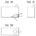
- FIG. 7A is a partly broken-away side view of the liquid container
- Fig. 7B is a bottom view thereof
- Fig. 7C is a front view thereof.
- the liquid container 1 is provided with a liquid containing portion 20 and a supply port as a liquid supplying portion provided in a portion of the liquid containing portion 20 for supplying the contained liquid to the recording head of the ink jet apparatus.
- a liquid holding member 3 for holding the liquid to be supplied to the recording head is contained in the liquid containing portion 20.
- the liquid container 1 shown thus has adopted a construction in which a single kind of liquid, e.g. black ink, is held in the liquid holding member 3 and a liquid supplying port 2 is provided for a recording head (e.g. a recording head for black ink) provided in an ink jet apparatus, whereby liquid is supplied at one by one.
- a single kind of liquid e.g. black ink
- a liquid supplying port 2 is provided for a recording head (e.g. a recording head for black ink) provided in an ink jet apparatus, whereby liquid is supplied at one by one.
- liquid container 1 in which a plurality of liquid containing portions 20 containing therein a plurality of liquids (e.g. cyan ink, magenta ink and yellow ink) are constructed integrally with one another, and again in such construction, only a single liquid supplying port 2 has been disposed for a liquid containing portion 20 containing a single kind of liquid therein.
- a plurality of liquid containing portions 20 containing therein a plurality of liquids e.g. cyan ink, magenta ink and yellow ink
- a liquid container is prepared for each recording head, but the disposition space for the liquid containers need be wide, thus resulting in the bulkiness of the apparatus.
- the present invention has been made in view of the above-described situation and an object thereof is to provide a liquid container which can substantially equalize the conditions of ink supply even when use is made of a plurality of recording heads discharging a single kind of ink, and achieves the stable supply of the ink.
- the present invention is a liquid container for an ink jet apparatus provided with a liquid containing portion containing a single kind of liquid therein, a supplying portion for directing the liquid outwardly from the liquid containing portion, and an atmosphere communicating portion for communicating the interior of the liquid containing portion with the atmosphere, and enabling the liquid to be supplied from the supplying portion to the recording element of the ink jet apparatus and providing a negative pressure source for the recording element, characterized in that a plurality of the supplying portions are disposed corresponding to a plurality of recording elements for the liquid containing portion so that the liquid can be supplied to the recording elements.
- a liquid holding member is contained in the liquid containing portion, and a fibrous member is disposed in the supplying portion.
- the performance of directing the liquid outwardly from the liquid container can be improved and the more stable performance of supplying the liquid can be achieved.
- the fibrous member may be in the form of a fiber bundle or the form of a felt material.
- the liquid containing portion is divided into a plurality of chambers, which are connected together by a communication opening portion.
- Only the liquid can be contained in the liquid container and an improvement in the quantity of contained ink can be achieved.
- the liquid containing portion is provided with a first chamber provided with a plurality of the supplying portions and the atmosphere communicating portion and having a liquid holding member contained therein, and a second chamber made into a substantially closed space except a communication opening portion provided for communication with the first chamber, and communicating with the first chamber only through the communication opening and containing therein the liquid to be supplied to the first chamber.
- the level of the liquid in the first chamber in which the liquid holding member is contained can be stabilized and the state of the negative pressure level relative to the recording elements can be stabilized. Therefore, stable liquid supply free of the irregularity of characteristic becomes possible to each recording element.
- the number of the plurality of supplying portions disposed in the first chamber is two, and the supplying portions are juxtaposed so that the distances thereof from the communication opening portion may be substantially equal to each other.
- the distances from the communication opening portion to the liquid supplying portions can be made equal to each other, the flow resistance of the liquid can be uniformized, and the liquid supplying properties can be adjusted to each other in the two supplying portions.
- respective ones of the central positions of the two supplying portions are disposed at locations spaced apart from two side walls constituting the liquid containing portion and adjacent to the supplying portions, by a distance obtained by substantially quartering the spacing between the side walls.
- the plurality of supplying portions in the liquid containing portion are disposed well-balancedly and therefore, the liquid supplying performance can be equalized irrespective of the supplying portions.
- black, cyan, magenta or yellow ink is contained in the liquid container.
- treating liquid is contained in the liquid container.
- the treating liquid mention may be made of one which reacts with ink and improves the fixativeness for a recording medium.
- the present invention is a liquid container for an ink jet apparatus provided with a liquid containing portion containing a single kind of liquid therein, a supplying portion for directing the liquid outwardly from the liquid containing portion, and an atmosphere communicating portion for communicating the interior of the liquid containing portion with the atmosphere, and enabling the liquid to be supplied from the supplying portion to the recording element of the ink jet apparatus, and providing a negative pressure source for the recording element, characterized in that the liquid containing portion has a plurality of the supplying portions, and is provided with a first chamber in which the atmosphere communicating portion and a liquid holding member are contained, and a second chamber made into a substantially closed space except a communication opening portion provided for communication with the first chamber, and communicating with the first chamber only through the communication opening and containing therein the liquid to be supplied to the first chamber, the number of the plurality of supplying portions disposed in the first chamber is two, and the supplying portions are juxtaposed so that the distances thereof from the communication opening portion may be substantially equal to each other.
- the level of the liquid in the first chamber in which the liquid holding member is contained can be stabilized, and the state of the negative pressure for the recording elements can be stabilized. Therefore, stable liquid supply free of the irregularity of characteristic becomes possible to each recording elements. Also, the plurality of supplying portions in the liquid containing portion are disposed well-balancedly and therefore, the liquid supplying performance can be equalized irrespective of the supplying portions. Further, the disposition space for the liquid container can be saved.
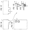
- Figs. 1A, 1B, 1C, 1D and 1E are schematic views of a liquid container having two liquid supplying ports according to Embodiment 1.
- Figs. 2A, 2B and 2C are views corresponding to Figs. 1A, 1B and 1C but showing a liquid container having two or more liquid supplying ports.
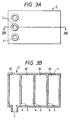
- Figs. 3A and 3B show a liquid container having a plurality of partition walls according to Embodiment 2.
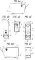
- Figs. 4A, 4B, 4C, 4D, 4E and 4F show a liquid container according to Embodiment 3.
- Fig. 5 is a cross-sectional view taken along the line 5 - 5 of Fig. 4B.
- Fig. 6 is a pictorial perspective view of the liquid container according to Embodiment 3.
- Figs. 7A, 7B and 7C are schematic views of an example of the liquid container according to the prior art.
- FIGS. 1A to 1E show an embodiment of a liquid container according to the present invention
- Figs. 1A, 1B and 1C being views schematically showing the construction of the liquid container
- Figs. 1D and 1E being cross-sectional views schematically showing the construction of a liquid supplying portion.
- the construction of the liquid container 1 for supplying liquid (e.g. ink) to two recording elements (recording heads, not shown) for discharging a single kind of liquid is disclosed.
- liquid e.g. ink
- two liquid supplying portions 2 connected to the two recording heads for supplying the ink are juxtaposed along the two sides of the liquid container 1 containing a single kind of liquid therein.
- the ink is supplied under a common ink supply condition, and the discharge states of the ink in the two recording heads can be stably equalized. Therefore, printing of high quality can be achieved without any irregularity of ink discharge, for example, in high-speed printing to be achieved by the two recording heads. Also, in high-density printing, the printing density can be stably uniformized.
- a liquid holding member 3 is contained in a liquid containing portion 20.
- the liquid (ink) is stored and held in the liquid containing portion 20, whereby negative pressure for the recording elements (recording heads, not shown) can be created.
- a continuous porous material such as polyurethane foam or a fibrous material can be used for the liquid holding material can be used for the liquid holding member 3, and it becomes possible to create the aforementioned negative pressure for the recording elements by the capillary force of these materials.
- the liquid supplying ports 2 are cylindrical hollow tubes projected outwardly from the liquid containing portion 20, and are connected to the supply pipes of the recording elements, whereby they are joined together and form a liquid supply route.
- the liquid supplying ports 2 need not always be such cylindrical hollow tubes, but may be formed as simple openings, and can be of any construction which can reliably achieve the joinder with the supply pipes of the recording elements.
- the liquid supplying port 2 may have a fibrous member 2a such as a felt material made of polypropylene or polyethylene or a fiber bundle member disposed therein.
- a fibrous member 2a such as a felt material made of polypropylene or polyethylene or a fiber bundle member disposed therein.
- the fibrous member 2a By such a fibrous member 2a being disposed, it becomes possible to improve the performance of directing the liquid (ink) outwardly from the liquid containing member 3 in the liquid containing portion 20.
- the liquid container 1 has an atmosphere communicating portion for communicating the interior thereof with the atmosphere.
- the present embodiment has been shown as a liquid container 1 storing therein a single kind of ink which is provided with two liquid supplying ports 2 connected to two recording heads for discharging the single kind of ink, but alternatively, as shown in Figs. 2A, 2B and 2C, the liquid container may be of a construction provided with three liquid supplying ports 2 corresponding to three recording heads for discharging a single kind of ink for which the liquid container 1 stores a single kind of ink therein.
- the same constituents as those in Figs. 1A to 1E are given the same reference numerals and need not be described.
- liquid container 1 may be provided with three or more liquid supplying ports 2.
- Figs. 3A and 3B show another embodiment of the present invention.
- the interior of the liquid containing portion 20 is divided into four by partition walls 5, and adjacent portions of the liquid containing portion 20 communicate with one another by minute communicating portions 6 provided between the partition walls 5 and the bottom of the liquid containing portion 20.
- a porous material or the like is not used as the liquid holding member 3, but the minute communicating portions 6 function as a creating source for negative pressure for the recording head (not shown). Thereby, the quantity per volume of the liquid which can be contained in the liquid container 1 can be increased.
- liquid supplying portions 2 are juxtaposed in a direction intersecting the both sides of the liquid container 1.
- Figs. 4A to 4F schematically show a liquid container as a liquid preserving region 1 according to Embodiment 3 of the present invention
- Fig. 4A being a left side view of the liquid preserving container 1
- Fig. 4B being a plan view thereof
- Fig. 4C being a front view thereof
- Fig. 4D being a right side view thereof
- Fig. 4E being a bottom plan view thereof
- Fig. 4F being a rear view.
- Fig. 5 is a cross-sectional view taken along the line 5 - 5 of Fig. 4B
- Fig. 6 is a pictorial perspective view of the liquid preserving container shown in Figs. 4A to 4F and 5.
- the liquid preserving container 1 is provided with a plurality of liquid supplying ports 2, a positioning member 12 and a latch lever 9 disposed on the sides of the container opposed to each other, and a pair of protective members 8 for sandwiching the latch lever 9 from the opposite sides thereof and protecting it.
- the interior of the liquid preserving container 1 is divided into a chamber (a second chamber) directly containing therein a liquid 4 contributing to recording and a chamber (a first chamber) containing a liquid holding member (a foamed member) 3 therein by a partition wall 5, and the two chambers communicate with each other through only an opening portion (communicating portion) 6 located at the bottom portion of the container 1.
- the liquid is supplied by the air and the liquid being exchanged in this communicating portion 6.
- the chamber containing the liquid holding member 3 therein is provided with the liquid supplying ports 2 for supplying therethrough the liquid to a recording head portion, not shown, and a vent port (atmosphere communicating portion) 7 for communicating the interior of this chamber with the atmosphere.
- the chamber containing the liquid 4 therein is provided with a liquid filling port 10 provided to fill the chamber with the liquid 4, and a seal member 11 for sealing the same. Consequently, the chamber containing the liquid 4 therein is a substantially hermetically sealed space except the communicating portion 6.
- the level of the liquid in the first chamber containing the liquid holding member therein can be stabilized and the state of the negative pressure level for the recording elements can be stabilized. Therefore, stable liquid supply free of the irregularity of characteristic for the respective recording elements becomes possible.
- two liquid supplying ports 2 are disposed in parallel near the side of the liquid preserving container 1 on which the positioning member 12 is disposed. Also, these two liquid supplying ports 2 are disposed at locations (l) substantially equal to each other in the distance from the communicating portion 6 formed in the container tank by the partition wall 5. Further, the center line (n) of the liquid supplying ports 2 is disposed so as to lie substantially at the center of the center line (m) of the liquid preserving container 1 and the side wall of the liquid preserving container 1.
- the flow resistance of the liquid from the communicating portion 6 can be substantially equalized by the two liquid supplying ports 2 and further, the states of the absorbing members in the two liquid supplying ports can be substantially equalized. Accordingly, it becomes possible to achieve well-balanced liquid supply free of irregularity by the two liquid supplying ports 2.
- a fibrous member 2a is disposed in each liquid supplying port 2 to thereby improve the supply property of the ink.
- the positioning member 12 and the latch lever 9 (which is provided with a pawl 9a engageable with a holder) and the protective member 8 for protecting the latch lever 9 are constituent members engageable with a holder, not shown, on which the liquid preserving container 1 is mounted, to thereby fix the liquid preserving container 1 relative to this holder.
- the liquid includes ink (black, magenta, yellow, cyan, etc.) contributing to recording as well as treating liquid used for image treatment.
- the present invention even when a plurality of recording elements are used, only one liquid container is required for a single kind of liquid (ink or treating liquid).
- the supplied liquid becomes equal in all recording elements and therefore, the irregularity of the discharging condition for the liquid can be suppressed. Also, the space in which the liquid container in the apparatus is disposed can be saved.
- the fibrous member may be in the form of a fiber bundle or the form of a felt material.
- the level of the liquid in the first chamber containing the liquid holding member therein can be stabilized, and the state of the negative pressure level for the recording elements can be stabilized. Therefore, stable liquid supply free of the irregularity of characteristic becomes possible to the respective recording elements.
- the distances from the communication opening portion to the liquid supplying portions can be made equal to each other and the flow resistance of the liquid can be uniformized and thus, the supplying properties of the liquid can be adjusted to each other in the two supplying portions.
- the plurality of supplying portions in the liquid containing portion are well-balancedly disposed and therefore, the liquid supplying performance can be uniformized irrespective of the supplying portions.
- the level of the liquid in the first chamber containing the liquid holding member therein can be stabilized, and the state of the negative pressure level for the recording elements can be stabilized. Therefore, stable liquid supply free of the irregularity of characteristic becomes possible to the respective recording elements. Also, the plurality of supplying portions in the liquid containing portion are well-balancedly disposed and therefore, the liquid supplying performance can be uniformized irrespective of the supplying portions. Further, the disposition space for the liquid container can be saved.
- liquid is supplied from a plurality of liquid supplying ports at a time to a plurality of recording elements for discharging the same liquid, with substantially equal flow resistance, and this leads to the following effects.
- the substances regarding the image design and printing pattern themselves as described above are not the purport of the present invention and therefore need not be described particularly in detail, but yet as long as the liquid preserving container according to the prior art is used, a plurality of liquid preserving containers are required for a plurality of recording elements, while according to the present invention, even if there are a plurality of recording elements, only a single liquid container is sufficient for a single kind of recording liquid and therefore, when an attempt is made to arrange liquid preserving containers in parallel in a recording apparatus, the internal space efficiency is improved and the entire recording apparatus becomes compact, and to a user, it is not necessary to prepare uselessly a number of liquid preserving containers as preliminary ones, and as compared with the liquid preserving container according to the prior art having a single liquid supplying port alone, the liquid preserving container of the present invention is improved in the liquid volume efficiency relative to the configuration of the container and therefore, there is further obtained the advantage of reduced working cost.
- a liquid container for an ink jet apparatus provision is made of means which requires only one liquid preserving container for a single kind of liquid even when a plurality of ink jet recording elements are used and which can also be expected to improve the printing density and the printing speed.
- a plurality of liquid supplying portions are provided in a liquid container having a liquid containing portion containing therein a sponge or the like for holding a single kind of liquid, and a liquid supplying port for supplying the liquid to ink jet recording elements.
Abstract
Description
Claims (27)
- A liquid container for an ink jet apparatus provided with a liquid containing portion containing a single kind of liquid therein, a supplying portion for directing the liquid outwardly from said liquid containing portion, and an atmosphere communicating portion for communicating the interior of said liquid containing portion with the atmosphere, and enabling the liquid to be supplied from said supplying portion to the recording element of the ink jet apparatus, and providing a negative pressure source for said recording element, characterized in that a plurality of said supplying portions are disposed correspondingly to a plurality of recording elements for said liquid containing portion so that the liquid can be supplied to said recording elements.
- A liquid container for an ink jet apparatus according to Claim 1, characterized in that a liquid holding member is contained in said liquid containing portion and a fibrous member is disposed in each of said supplying portions.
- A liquid container for an ink jet apparatus according to Claim 1, characterized in that said liquid containing portion is divided into a plurality of chambers, which are connected together by a communication opening portion.
- A liquid container for an ink jet apparatus according to Claim 1, characterized in that said liquid containing portion is provided with a first chamber provided with a plurality of said supplying portions and said atmosphere communicating portion and having a liquid holding member contained therein, and a second chamber made into a substantially closed space except a communication opening portion provided for communication with said first chamber, and communicating with said first chamber only through said communication opening and containing therein the liquid to be supplied to said first chamber.
- A liquid container for an ink jet apparatus according to Claim 4, characterized in that the number of the plurality of supplying portions disposed in said first chamber is two, and the supplying portions are juxtaposed so that the distances thereof from said communication opening portion may be substantially equal to each other.
- A liquid container for an ink jet apparatus according to Claim 5, characterized in that respective ones of the central positions of said two supplying portions are disposed at locations spaced apart from two side walls constituting said liquid containing portion and adjacent to said supplying portions, by a distance obtained by substantially quartering the spacing between said two side walls.
- A liquid container for an ink jet apparatus according to Claim 1, characterized in that black, cyan, magenta or yellow ink is contained in said liquid container.
- A liquid container for an ink jet apparatus according to Claim 2, characterized in that black, cyan, magenta or yellow ink is contained in said liquid container.
- A liquid container for an ink jet apparatus according to Claim 3, characterized in that black, cyan, magenta or yellow ink is contained in said liquid container.
- A liquid container for an ink jet apparatus according to Claim 4, characterized in that black, cyan, magenta or yellow ink is contained in said liquid container.
- A liquid container for an ink jet apparatus according to Claim 5, characterized in that black, cyan, magenta or yellow ink is contained in said liquid container.
- A liquid container for an ink jet apparatus according to Claim 6, characterized in that black, cyan, magenta or yellow ink is contained in said liquid container.
- A liquid container for an ink jet apparatus according to Claim 1, characterized in that treating liquid is contained in said liquid container.
- A liquid container for an ink jet apparatus according to Claim 2, characterized in that treating liquid is contained in said liquid container.
- A liquid container for an ink jet apparatus according to Claim 3, characterized in that treating liquid is contained in said liquid container.
- A liquid container for an ink jet apparatus according to Claim 4, characterized in that treating liquid is contained in said liquid container.
- A liquid container for an ink jet apparatus according to Claim 5, characterized in that treating liquid is contained in said liquid container.
- A liquid container for an ink jet apparatus according to Claim 6, characterized in that treating liquid is contained in said liquid container.
- A liquid container for an ink jet apparatus provided with a liquid containing portion containing a single kind of liquid therein, a supplying portion for directing the liquid outwardly from said liquid containing portion, and an atmosphere communicating portion for communicating the interior of said liquid containing portion with the atmosphere, and enabling the liquid to be supplied from said supplying portion to the recording element of the ink jet apparatus, and providing a negative pressure source for said recording element, characterized in that said liquid containing portion has a plurality of said supplying portions, and is provided with a first chamber in which said atmosphere communicating portion and a liquid holding member are contained, and a second chamber made into a substantially closed space except a communication opening position provided for communication with said first chamber, and communicating with said first chamber only through said communication opening and containing therein the liquid to be supplied to said first chamber, the number of said plurality of supplying portions disposed in said first chamber is two, and said supplying portions are juxtaposed so that the distances thereof from said communication opening portion may be substantially equal to each other.
- A liquid container for an ink jet apparatus according to Claim 9, characterized in that respective ones of the central positions of said two supplying portions are disposed at locations spaced apart from two side walls constituting said liquid containing portion and adjacent to said supplying portions, by a distance obtained by substantially quartering the spacing between said side walls.
- A liquid container for an ink jet apparatus according to Claim 9, characterized in that a fibrous member is disposed in each of said supplying portions.
- A liquid container for an ink jet apparatus according to Claim 10, characterized in that a fibrous member is disposed in each of said supplying portions.
- A liquid container for an ink jet apparatus according to Claim 9, characterized in that black, cyan or magenta ink is contained in said liquid container.
- A liquid container for an ink jet apparatus according to Claim 10, characterized in that black, cyan or magenta ink is contained in said liquid container.
- A liquid container for an ink jet apparatus according to Claim 9, characterized in that treating liquid is contained in said liquid container.
- A liquid container for an ink jet apparatus according to Claim 10, characterized in that treating liquid is contained in said liquid container.
- A liquid container for an ink jet apparatus according to Claim 9, characterized in that the number of recording elements for discharging said single kind of liquid is two.
Applications Claiming Priority (6)
| Application Number | Priority Date | Filing Date | Title |
|---|---|---|---|
| JP20214096 | 1996-07-31 | ||
| JP20214096 | 1996-07-31 | ||
| JP202140/96 | 1996-07-31 | ||
| JP35057/97 | 1997-02-19 | ||
| JP3505797 | 1997-02-19 | ||
| JP03505797A JP3332779B2 (en) | 1996-07-31 | 1997-02-19 | Liquid storage container for inkjet recording device |
Publications (3)
| Publication Number | Publication Date |
|---|---|
| EP0822083A2 true EP0822083A2 (en) | 1998-02-04 |
| EP0822083A3 EP0822083A3 (en) | 1999-06-02 |
| EP0822083B1 EP0822083B1 (en) | 2002-10-23 |
Family
ID=26373966
Family Applications (1)
| Application Number | Title | Priority Date | Filing Date |
|---|---|---|---|
| EP97113151A Expired - Lifetime EP0822083B1 (en) | 1996-07-31 | 1997-07-30 | Liquid container for an ink jet recording apparatus |
Country Status (9)
| Country | Link |
|---|---|
| US (1) | US6203148B1 (en) |
| EP (1) | EP0822083B1 (en) |
| JP (1) | JP3332779B2 (en) |
| KR (1) | KR100235158B1 (en) |
| CN (1) | CN1070781C (en) |
| AU (1) | AU738419B2 (en) |
| CA (1) | CA2211936C (en) |
| DE (1) | DE69716530T2 (en) |
| ES (1) | ES2184942T3 (en) |
Cited By (5)
| Publication number | Priority date | Publication date | Assignee | Title |
|---|---|---|---|---|
| FR2827216A1 (en) * | 2001-07-13 | 2003-01-17 | Leroux Gilles Sa | Ink jet printer has externally supplied pneumatic system and ink reservoir on printing module which is segmented either rectangularly or with honeycombe structure and connected to fixed reservoir |
| WO2003006247A1 (en) * | 2001-07-13 | 2003-01-23 | Gilles Leroux S.A. | Inkjet digital printing device and ink reservoir |
| US6921161B2 (en) | 1998-09-01 | 2005-07-26 | Canon Kabushiki Kaisha | Liquid container, cartridge including liquid container, printing apparatus using cartridge and liquid-discharge printing apparatus |
| EP2065202A1 (en) * | 2007-11-30 | 2009-06-03 | Brother Kogyo Kabushiki Kaisha | Liquid droplet jetting apparatus |
| WO2018048416A1 (en) * | 2016-09-09 | 2018-03-15 | Hewlett-Packard Development Company, L.P. | Latch protector |
Families Citing this family (24)
| Publication number | Priority date | Publication date | Assignee | Title |
|---|---|---|---|---|
| JP4747503B2 (en) * | 2001-04-03 | 2011-08-17 | セイコーエプソン株式会社 | Ink cartridge for ink jet recording apparatus |
| TWI259149B (en) * | 2002-09-30 | 2006-08-01 | Canon Kk | Ink container and recording apparatus |
| US7134747B2 (en) * | 2002-09-30 | 2006-11-14 | Canon Kabushiki Kaisha | Ink container, recording head and recording device using same |
| TWI293317B (en) * | 2003-12-31 | 2008-02-11 | Ind Tech Res Inst | Method for preparing polymer microspheres by aqueous phase-aqueous phase emulsion process |
| US20050151807A1 (en) * | 2004-01-12 | 2005-07-14 | Nu-Kote International, Inc., A Corporation Of Delaware | Ink container for an ink jet cartridge |
| US20070035596A1 (en) * | 2005-08-10 | 2007-02-15 | Lexmark International, Inc. | Ink jet cartridge |
| US20070076065A1 (en) * | 2005-09-30 | 2007-04-05 | Lexmark International, Inc. | Ink tank with an air prevention component |
| JP2007144827A (en) * | 2005-11-29 | 2007-06-14 | Ricoh Co Ltd | Liquid container, ink supply unit, and image forming apparatus |
| JP2009132036A (en) | 2007-11-30 | 2009-06-18 | Brother Ind Ltd | Liquid droplet jetting apparatus |
| JP4872894B2 (en) | 2007-11-30 | 2012-02-08 | ブラザー工業株式会社 | Droplet ejector |
| EP2661373B1 (en) | 2011-01-07 | 2016-08-31 | Hewlett-Packard Development Company, L.P. | Fluid container having plurality of chambers |
| BR112013017252B1 (en) | 2011-01-07 | 2020-09-01 | Hewlett-Packard Development Company, Lp | USEFUL INTEGRATED MULTIFUNCTIONAL VALVE DEVICE WITH A FLUID CONTAINER AND USEFUL FLUID CONTAINER WITH AN IMAGE FORMATION MECHANISM |
| EP2661372B1 (en) | 2011-01-07 | 2014-10-01 | Hewlett-Packard Development Company, L.P. | Fluid container having plurality of chambers and valves |
| JP6060544B2 (en) | 2012-05-23 | 2017-01-18 | セイコーエプソン株式会社 | Liquid container and container unit |
| EP2666638B1 (en) | 2012-05-23 | 2016-01-06 | Seiko Epson Corporation | Cover and liquid container |
| US8894184B2 (en) | 2012-05-23 | 2014-11-25 | Seiko Epson Corporation | Cover and liquid container |
| CN103419500B (en) | 2012-05-23 | 2015-10-21 | 精工爱普生株式会社 | Box and seal member |
| JP6028424B2 (en) | 2012-07-06 | 2016-11-16 | セイコーエプソン株式会社 | Printing material supply system and cartridge thereof |
| JP6069964B2 (en) | 2012-07-23 | 2017-02-01 | セイコーエプソン株式会社 | Cartridge manufacturing method, injection kit, and injection device |
| US9776418B2 (en) | 2012-07-23 | 2017-10-03 | Seiko Epson Corporation | Method and apparatus for manufacturing cartridge |
| US10647123B2 (en) | 2012-07-23 | 2020-05-12 | Seiko Epson Corporation | Refilled cartridge and method for manufacturing refilled cartridge |
| JP5962292B2 (en) * | 2012-07-23 | 2016-08-03 | セイコーエプソン株式会社 | cartridge |
| JP6048004B2 (en) | 2012-07-23 | 2016-12-21 | セイコーエプソン株式会社 | cartridge |
| WO2019094022A1 (en) * | 2017-11-10 | 2019-05-16 | Hewlett-Packard Development Company, L.P. | Fluidic cartridges |
Citations (5)
| Publication number | Priority date | Publication date | Assignee | Title |
|---|---|---|---|---|
| US4771295A (en) * | 1986-07-01 | 1988-09-13 | Hewlett-Packard Company | Thermal ink jet pen body construction having improved ink storage and feed capability |
| EP0542247A2 (en) * | 1991-11-12 | 1993-05-19 | Canon Kabushiki Kaisha | Liquid container, recording head using same and recording apparatus using same |
| EP0624475A2 (en) * | 1993-05-13 | 1994-11-17 | Canon Kabushiki Kaisha | Ink tank, head cartridge and ink jet printing apparatus |
| EP0639462A2 (en) * | 1993-08-19 | 1995-02-22 | Canon Kabushiki Kaisha | Ink tank cartridge and ink-jet apparatus in which the ink tank cartridge is installed |
| JPH08192520A (en) * | 1995-01-19 | 1996-07-30 | Canon Inc | Ink jet recording head and recording apparatus |
Family Cites Families (3)
| Publication number | Priority date | Publication date | Assignee | Title |
|---|---|---|---|---|
| US4539569A (en) * | 1982-10-26 | 1985-09-03 | Canon Kabushiki Kaisha | Ink jet recording apparatus |
| JPH03288652A (en) * | 1990-04-04 | 1991-12-18 | Sharp Corp | Ink cartridge and ink supply device |
| CA2101017C (en) * | 1992-07-24 | 1999-10-26 | Masahiko Higuma | Ink jet cartridge, ink jet head and printer |
-
1997
- 1997-02-19 JP JP03505797A patent/JP3332779B2/en not_active Expired - Fee Related
- 1997-07-28 US US08/901,647 patent/US6203148B1/en not_active Expired - Lifetime
- 1997-07-30 EP EP97113151A patent/EP0822083B1/en not_active Expired - Lifetime
- 1997-07-30 AU AU32394/97A patent/AU738419B2/en not_active Ceased
- 1997-07-30 DE DE69716530T patent/DE69716530T2/en not_active Expired - Lifetime
- 1997-07-30 CA CA002211936A patent/CA2211936C/en not_active Expired - Fee Related
- 1997-07-30 KR KR1019970036058A patent/KR100235158B1/en not_active IP Right Cessation
- 1997-07-30 ES ES97113151T patent/ES2184942T3/en not_active Expired - Lifetime
- 1997-07-30 CN CN97114764A patent/CN1070781C/en not_active Expired - Fee Related
Patent Citations (6)
| Publication number | Priority date | Publication date | Assignee | Title |
|---|---|---|---|---|
| US4771295A (en) * | 1986-07-01 | 1988-09-13 | Hewlett-Packard Company | Thermal ink jet pen body construction having improved ink storage and feed capability |
| US4771295B1 (en) * | 1986-07-01 | 1995-08-01 | Hewlett Packard Co | Thermal ink jet pen body construction having improved ink storage and feed capability |
| EP0542247A2 (en) * | 1991-11-12 | 1993-05-19 | Canon Kabushiki Kaisha | Liquid container, recording head using same and recording apparatus using same |
| EP0624475A2 (en) * | 1993-05-13 | 1994-11-17 | Canon Kabushiki Kaisha | Ink tank, head cartridge and ink jet printing apparatus |
| EP0639462A2 (en) * | 1993-08-19 | 1995-02-22 | Canon Kabushiki Kaisha | Ink tank cartridge and ink-jet apparatus in which the ink tank cartridge is installed |
| JPH08192520A (en) * | 1995-01-19 | 1996-07-30 | Canon Inc | Ink jet recording head and recording apparatus |
Non-Patent Citations (1)
| Title |
|---|
| PATENT ABSTRACTS OF JAPAN vol. 96, no. 11, 29 November 1996 & JP 08 192520 A (CANON INC), 30 July 1996 * |
Cited By (8)
| Publication number | Priority date | Publication date | Assignee | Title |
|---|---|---|---|---|
| US6921161B2 (en) | 1998-09-01 | 2005-07-26 | Canon Kabushiki Kaisha | Liquid container, cartridge including liquid container, printing apparatus using cartridge and liquid-discharge printing apparatus |
| FR2827216A1 (en) * | 2001-07-13 | 2003-01-17 | Leroux Gilles Sa | Ink jet printer has externally supplied pneumatic system and ink reservoir on printing module which is segmented either rectangularly or with honeycombe structure and connected to fixed reservoir |
| WO2003006247A1 (en) * | 2001-07-13 | 2003-01-23 | Gilles Leroux S.A. | Inkjet digital printing device and ink reservoir |
| US7344231B2 (en) | 2001-07-13 | 2008-03-18 | Datacard Corporation | Inkjet digital printing device and ink reservoir |
| EP2065202A1 (en) * | 2007-11-30 | 2009-06-03 | Brother Kogyo Kabushiki Kaisha | Liquid droplet jetting apparatus |
| US8091994B2 (en) | 2007-11-30 | 2012-01-10 | Brother Kogyo Kabushiki Kaisha | Liquid droplet jetting apparatus including liquid tank and two heads connected in series |
| WO2018048416A1 (en) * | 2016-09-09 | 2018-03-15 | Hewlett-Packard Development Company, L.P. | Latch protector |
| US10836174B2 (en) | 2016-09-09 | 2020-11-17 | Hewlett-Packard Development Company, L.P. | Latch protector |
Also Published As
| Publication number | Publication date |
|---|---|
| AU3239497A (en) | 1998-02-05 |
| EP0822083A3 (en) | 1999-06-02 |
| JPH1095129A (en) | 1998-04-14 |
| CA2211936A1 (en) | 1998-01-31 |
| DE69716530T2 (en) | 2003-03-20 |
| ES2184942T3 (en) | 2003-04-16 |
| US6203148B1 (en) | 2001-03-20 |
| EP0822083B1 (en) | 2002-10-23 |
| KR100235158B1 (en) | 1999-12-15 |
| CN1070781C (en) | 2001-09-12 |
| KR980008580A (en) | 1998-04-30 |
| CN1172018A (en) | 1998-02-04 |
| AU738419B2 (en) | 2001-09-20 |
| DE69716530D1 (en) | 2002-11-28 |
| JP3332779B2 (en) | 2002-10-07 |
| CA2211936C (en) | 2002-06-25 |
Similar Documents
| Publication | Publication Date | Title |
|---|---|---|
| EP0822083B1 (en) | Liquid container for an ink jet recording apparatus | |
| US5182581A (en) | Ink jet recording unit having an ink tank section containing porous material and a recording head section | |
| US7488067B2 (en) | Liquid container, liquid ejection device and liquid container case | |
| JP3745161B2 (en) | Liquid storage container | |
| US4447820A (en) | Ink supplying mechanism | |
| US4855762A (en) | Ink storing device | |
| US6719416B2 (en) | Ink container package | |
| GB2293141A (en) | Multi-chambered ink cartridge for ink jet printer. | |
| JP2003025603A (en) | Ink tank | |
| EP0875383B1 (en) | Ink tank, ink jet cartridge, and ink filling method | |
| JP4655503B2 (en) | Liquid container | |
| JP2006199037A (en) | Replaceable type ink feeding source | |
| US20030001933A1 (en) | Ink cartridge | |
| US7488061B2 (en) | Ink cartridge replacement lid | |
| JPH0825644A (en) | Ink tank and ink jet device using ink tank | |
| JPH10278290A (en) | Ink tank for ink jet recorder | |
| JPH0776098A (en) | Ink cartridge for ink jet device | |
| JP3173601B2 (en) | Ink cartridge for inkjet recording device | |
| CN217863351U (en) | Ink box with high volume utilization rate | |
| JPH10119313A (en) | Ink feed device and ink jet recording device | |
| JP2002361899A (en) | Ink cartridge and printer comprising it | |
| JP2002331683A (en) | Ink tank | |
| JPH10175310A (en) | Ink cartridge unit and refill device | |
| JP2002331681A (en) | Liquid container | |
| JP2001105621A (en) | Liquid housing container, package thereof, ink jet head cartridge wherein liquid housing container and recording head are integrated and recording apparatus |
Legal Events
| Date | Code | Title | Description |
|---|---|---|---|
| PUAI | Public reference made under article 153(3) epc to a published international application that has entered the european phase |
Free format text: ORIGINAL CODE: 0009012 |
|
| AK | Designated contracting states |
Kind code of ref document: A2 Designated state(s): DE ES FR GB IT |
|
| AX | Request for extension of the european patent |
Free format text: AL;LT;LV;RO;SI |
|
| PUAL | Search report despatched |
Free format text: ORIGINAL CODE: 0009013 |
|
| AK | Designated contracting states |
Kind code of ref document: A3 Designated state(s): AT BE CH DE DK ES FI FR GB GR IE IT LI LU MC NL PT SE |
|
| AX | Request for extension of the european patent |
Free format text: AL;LT;LV;RO;SI |
|
| 17P | Request for examination filed |
Effective date: 19991022 |
|
| AKX | Designation fees paid |
Free format text: DE ES FR GB IT |
|
| GRAG | Despatch of communication of intention to grant |
Free format text: ORIGINAL CODE: EPIDOS AGRA |
|
| 17Q | First examination report despatched |
Effective date: 20020116 |
|
| GRAG | Despatch of communication of intention to grant |
Free format text: ORIGINAL CODE: EPIDOS AGRA |
|
| GRAH | Despatch of communication of intention to grant a patent |
Free format text: ORIGINAL CODE: EPIDOS IGRA |
|
| GRAH | Despatch of communication of intention to grant a patent |
Free format text: ORIGINAL CODE: EPIDOS IGRA |
|
| GRAA | (expected) grant |
Free format text: ORIGINAL CODE: 0009210 |
|
| AK | Designated contracting states |
Kind code of ref document: B1 Designated state(s): DE ES FR GB IT |
|
| REG | Reference to a national code |
Ref country code: GB Ref legal event code: FG4D |
|
| REF | Corresponds to: |
Ref document number: 69716530 Country of ref document: DE Date of ref document: 20021128 |
|
| REG | Reference to a national code |
Ref country code: ES Ref legal event code: FG2A Ref document number: 2184942 Country of ref document: ES Kind code of ref document: T3 |
|
| ET | Fr: translation filed | ||
| PLBE | No opposition filed within time limit |
Free format text: ORIGINAL CODE: 0009261 |
|
| STAA | Information on the status of an ep patent application or granted ep patent |
Free format text: STATUS: NO OPPOSITION FILED WITHIN TIME LIMIT |
|
| 26N | No opposition filed |
Effective date: 20030724 |
|
| REG | Reference to a national code |
Ref country code: FR Ref legal event code: PLFP Year of fee payment: 19 |
|
| PGFP | Annual fee paid to national office [announced via postgrant information from national office to epo] |
Ref country code: ES Payment date: 20150714 Year of fee payment: 19 Ref country code: DE Payment date: 20150731 Year of fee payment: 19 Ref country code: GB Payment date: 20150727 Year of fee payment: 19 |
|
| PGFP | Annual fee paid to national office [announced via postgrant information from national office to epo] |
Ref country code: FR Payment date: 20150729 Year of fee payment: 19 |
|
| PGFP | Annual fee paid to national office [announced via postgrant information from national office to epo] |
Ref country code: IT Payment date: 20150708 Year of fee payment: 19 |
|
| REG | Reference to a national code |
Ref country code: DE Ref legal event code: R119 Ref document number: 69716530 Country of ref document: DE |
|
| GBPC | Gb: european patent ceased through non-payment of renewal fee |
Effective date: 20160730 |
|
| PG25 | Lapsed in a contracting state [announced via postgrant information from national office to epo] |
Ref country code: DE Free format text: LAPSE BECAUSE OF NON-PAYMENT OF DUE FEES Effective date: 20170201 Ref country code: FR Free format text: LAPSE BECAUSE OF NON-PAYMENT OF DUE FEES Effective date: 20160801 |
|
| REG | Reference to a national code |
Ref country code: FR Ref legal event code: ST Effective date: 20170331 |
|
| PG25 | Lapsed in a contracting state [announced via postgrant information from national office to epo] |
Ref country code: GB Free format text: LAPSE BECAUSE OF NON-PAYMENT OF DUE FEES Effective date: 20160730 |
|
| PG25 | Lapsed in a contracting state [announced via postgrant information from national office to epo] |
Ref country code: IT Free format text: LAPSE BECAUSE OF NON-PAYMENT OF DUE FEES Effective date: 20160730 |
|
| REG | Reference to a national code |
Ref country code: ES Ref legal event code: FD2A Effective date: 20180507 |
|
| PG25 | Lapsed in a contracting state [announced via postgrant information from national office to epo] |
Ref country code: ES Free format text: LAPSE BECAUSE OF NON-PAYMENT OF DUE FEES Effective date: 20160731 |