EP0818308A1 - Method and apparatus for recording information in a record medium - Google Patents
Method and apparatus for recording information in a record medium Download PDFInfo
- Publication number
- EP0818308A1 EP0818308A1 EP97304957A EP97304957A EP0818308A1 EP 0818308 A1 EP0818308 A1 EP 0818308A1 EP 97304957 A EP97304957 A EP 97304957A EP 97304957 A EP97304957 A EP 97304957A EP 0818308 A1 EP0818308 A1 EP 0818308A1
- Authority
- EP
- European Patent Office
- Prior art keywords
- beams
- threshold
- record medium
- recording
- information
- Prior art date
- Legal status (The legal status is an assumption and is not a legal conclusion. Google has not performed a legal analysis and makes no representation as to the accuracy of the status listed.)
- Ceased
Links
Images

Classifications
-
- H—ELECTRICITY
- H04—ELECTRIC COMMUNICATION TECHNIQUE
- H04N—PICTORIAL COMMUNICATION, e.g. TELEVISION
- H04N1/00—Scanning, transmission or reproduction of documents or the like, e.g. facsimile transmission; Details thereof
- H04N1/40—Picture signal circuits
- H04N1/40025—Circuits exciting or modulating particular heads for reproducing continuous tone value scales
- H04N1/40037—Circuits exciting or modulating particular heads for reproducing continuous tone value scales the reproducing element being a laser
-
- B—PERFORMING OPERATIONS; TRANSPORTING
- B41—PRINTING; LINING MACHINES; TYPEWRITERS; STAMPS
- B41C—PROCESSES FOR THE MANUFACTURE OR REPRODUCTION OF PRINTING SURFACES
- B41C1/00—Forme preparation
- B41C1/055—Thermographic processes for producing printing formes, e.g. with a thermal print head
Definitions
- the invention relates to methods and apparatus for recording information in a record medium.
- thermal imaging is achieved by heating the plate in an oven or the like and then transferring the plate to an output device on which the image is then reproduced.
- This has a number of problems. Firstly, it is necessary to handle the hot plate during transfer from the oven to the output device and secondly throughout this process, the plate is cooling down so that areas towards the end of an imaging process will be cooler than areas at the beginning. This can lead to variability in the quality of reproduction due to variations in recorded spot size.
- a further problem with the existing technology is that in order to increase imaging speeds, arrays of exposing radiation beams are used.
- the power requirement for the beams is very high even when used to expose a thermal imaging plate transferred from an oven and it is not possible to achieve rapid modulation at such high power levels.
- a method of recording information in a record medium in which information is recorded in a region of the medium only when the region is subjected to an energy level above a threshold comprises:
- apparatus for recording information in a record medium in which the information is recorded in a region of the medium only when the region is subjected to an energy level above the threshold comprises a record medium support; an array of first recording beam generators for generating a corresponding array of first recording beams which impinge upon a record medium on the support and which are modulated in accordance with the information to be recorded, the energy level of the first recording beams never exceeding the threshold; and a second radiation beam generator for exposing the record medium to a second radiation beam, before, and/or during, and/or after exposure to the first recording beams, the second radiation beam having an energy level less than the threshold but sufficiently high that the total energy in a region where information is to be recorded exceeds the threshold when that region has been exposed to both the first and second beams within the thermal time constant of the medium.
- first beams instead of separately heating the record medium in an oven or the like and then transferring it to the output device, we carry out both the processes (heating and imaging) with the record medium in situ.
- This allows the first beams to have an energy level less than the second beam so that the first beams can be modulated at high modulation rates thus achieving the desired productivity rate while the second beam, which is normally unmodulated, provides the necessary additional heat to achieve recordal of the information.
- This is particularly useful when an array of first radiation beams are used since they can be modulated at much faster rates in view of the lower power requirements than has been possible up to now.
- Many first radiation beams could be used, for example, up to 64 or more, typically arranged in a linear or two dimensional array.
- the second radiation beam will have a similar form to the overall dimensions of the first recording beam but other forms of second radiation beam could be used, for example having an elongate dimension as would be generated from a bar-like source.
- the first and second beam generators are mounted on a common expose head.
- the second radiation beam generator could be mounted separately from the first recording beam generators.
- the first and second beam generators can be implemented in any conventional form.
- at least the second radiation beam generator is in the form of an array of generators such as LEDs, typically a linear array, to provide an illumination source which is broad and flat-topped in one axis while having a lambertian cross-section in the other. It would also be possible to use multi-dimensional arrays of sources.
- first radiation beam generators for example LEDs or laser diodes
- second beam(s) would need to be present over the full extent of the first beams within the period of the thermal time constant of the medium.
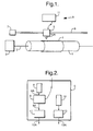
- the apparatus shown in Figure 1 comprises a drum 1 mounted to an axle 2 which is connected to a motor 3.
- a thermal imaging plate 4 on which an image is to be recorded is mounted on the drum 1.
- a typical example of such a thermal imaging plate is a Dupont thermal imaging plate.
- an expose head 5 mounted for movement alongside the drum 1 is an expose head 5 supported on a lead screw 6 which is connected to a motor 7.
- the motor 3 rotates the axle 2 and hence the drum 1 at a relatively fast speed while the motor 7 rotates the lead screw 6 at a slower speed so that the expose head 5 scans across the entire surface of the thermal imaging plate 4.
- the main components of the expose head 5 are shown in Figure 2.
- the expose head 5 includes a linear (one-dimensional) array of first, low power lasers 8 each of which generates a laser beam 8A which is fed to a respective acousto-optic modulator 9, the modulated beams 9A being fed to expose optics 10, the resultant modulated beams 6A then exiting the expose head 5 and impinging on the plate 4.
- the acousto-optic modulators 9 are controlled from a controller 11 in a conventional manner so that the beams are modulated (typically ON/OFF) in accordance with predetermined image information defining the digital colour component content of pixels of the image.
- predetermined image information typically, in the case of a half-tone representation, four colour separation plates will be generated by this process.
- lasers 8 there will be a multiplicity of lasers 8, for example up to 64. These will normally be arranged in a rectilinear fashion parallel with the axis of the drum 1 but other types of array are also possible including two dimensional arrays.
- any suitable modulating source that uses direct or indirect modulation could be used in place of the lasers 8 and the modulators 9.
- the modulation could be achieved by the switching of a diode laser, by the use of an electro-optic modulator or by amplitude modulation using a spatial light modulator.
- the power level of each laser 8 is typically relatively low, of the order of a few watts and is insufficient to record information in the plate 4 since the power level does not exceed the imaging threshold of the plate: 100 mJ/cm 2 .
- the expose head 5 includes a second, higher power laser 12 of the order of a few tens of watts which generates an unmodulated laser beam which is fed to optics 13, the resultant high power beam being directed to impinge upon the plate 4 just behind the point of impingement of the beams from the lasers 8.
- the plate has sufficient thermal memory to retain the heat generated upon exposure to the beams from the lasers 8 until it is exposed to the beam from the source 12.
- the beam 13A generated by the source 12 and optics 13 can take a variety of forms, provided the required power density is present, but will typically have a Guassian energy distribution as will the beams from the lasers 8.
- each beam has a diameter of about 10 microns.
- the beams may be arranged to impinge on identical regions of the medium record substantially simultaneously providing the two beams are mutually incoherent. They can be of different wavelengths depending on the sensitivity of the plate material. Alternatively, they can impinge on adjacent regions, sufficient heat being transferred laterally to achieve exposure where appropriate.
- the beam from the source 12 could be arranged to impinge on the record medium 4 before the beams from the lasers 8.
- the higher power radiation could be generated from a source separate from the expose head 5.
- a bar-like heater could be positioned alongside the drum 1 adjacent the position at which the beams from the lasers 8 impinge on the plate 4.
- the apparatus described could also be used for imaging a conventional silver lith plate simply by switching off the laser 12.
- Two means of providing pre-exposure are considered the first using a laser source of the required power and the second using some form of uniform illumination.
- two gaussian beams are combined to give the required exposure.
- One beam is on constantly and brings the power at the plate material to just below the exposure threshold.
- the second beam is modulated to provide the additional power required to properly expose the plate.
- the two beams are completely incoherent, their combined effect will be given by the algebraic sum of the separate constituent waves in intensity space.
- the resultant intensity at the plate will, therefore, be the sum of the component intensities.
- the 1/e 2 beam diameter of the resultant beam will be the same 1/e 2 beam diameter as that of the constituent beams provided they are identical when specified.
- the two beams can, therefore, be optically manipulated to give the required 1/e 2 beam diameter. This will be true for any chosen "beam diameter”.
- the modulated beam will still have to be of very high power.
- An alternative approach would be to uniformly illuminate the medium with a source which will give the same equivalent power level just below the exposure threshold of the material.
- the modulating beam will still have to be of power P3 to achieve correct exposure.
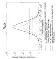
- Figure 3 is a plot to compare illumination requirement.
- the modulating beam will also have to be of high power so this scheme may not be of great benefit.
- the modulating mean can be of low power, just enough for efficient imaging.
- Threshold 5 ⁇ 10 4 ⁇ joule (10 -2 ⁇ m ) 2
- Threshold 5 ⁇ 10 8 ⁇ m -2 ⁇ sec ⁇ watt
- Irr Threshold sec
- Irr 5 ⁇ 10 8 ⁇ m -2 ⁇ watt is the required power to achieve threshold.
- Figure 4 illustrates the illumination requirements for the Example.
Abstract
Apparatus for recording information in a record medium
such as a printing plate (4) in which the information is
recorded in a region of the medium only when the region is
subjected to an energy level above the threshold. The
apparatus comprises a record medium support (1); and an
array of first recording beam generators (8) for generating
a corresponding array of first recording beams (10A) which
impinge upon a record medium (4) on the support (1) and
which are modulated in accordance with the information to
be recorded, the energy level of the first recording beams
(10A) never exceeding the threshold.
A second radiation beam generator (12) exposes the
record medium (4) to a second radiation beam (13A), before,
and/or during, and/or after exposure to the first recording
beams (10A). The second radiation beam (13A) has an energy
level less than the threshold but sufficiently high that
the total energy in a region where information is to be
recorded exceeds the threshold when that region has been
exposed to both the first and second beams within the
thermal time constant of the medium.
Description
The invention relates to methods and apparatus for
recording information in a record medium.
Conventional imaging systems for making printing
plates make use of silver lith technology which requires
approximately an exposure energy level of 2 µJ cm-2 in order
to expose a pixel. Recently, new plate technology has been
introduced based on a thermal imaging process which
requires much higher energy levels of the order of 200 mJ
cm-2. This is a jump in energy requirements of 100,000.
Furthermore, the modern market requires an increase of ten
times in productivity and overall this equates to an
increase of 106 in technology. Current technology cannot
meet these demands. In order to meet the productivity
requirements, very high modulation rates of an exposure
beam would be needed but these cannot be achieved in
conjunction with the high power requirements of the thermal
imaging plates.
At present, thermal imaging is achieved by heating the
plate in an oven or the like and then transferring the
plate to an output device on which the image is then
reproduced. This has a number of problems. Firstly, it is
necessary to handle the hot plate during transfer from the
oven to the output device and secondly throughout this
process, the plate is cooling down so that areas towards
the end of an imaging process will be cooler than areas at
the beginning. This can lead to variability in the quality
of reproduction due to variations in recorded spot size.
A further problem with the existing technology is that
in order to increase imaging speeds, arrays of exposing
radiation beams are used. However, the power requirement
for the beams is very high even when used to expose a
thermal imaging plate transferred from an oven and it is
not possible to achieve rapid modulation at such high power
levels.
In accordance with one aspect of the present
invention, a method of recording information in a record
medium in which information is recorded in a region of the
medium only when the region is subjected to an energy level
above a threshold comprises:
In accordance with a second aspect of the present
invention, apparatus for recording information in a record
medium in which the information is recorded in a region of
the medium only when the region is subjected to an energy
level above the threshold comprises a record medium
support; an array of first recording beam generators for
generating a corresponding array of first recording beams
which impinge upon a record medium on the support and which
are modulated in accordance with the information to be
recorded, the energy level of the first recording beams
never exceeding the threshold; and a second radiation beam
generator for exposing the record medium to a second
radiation beam, before, and/or during, and/or after
exposure to the first recording beams, the second radiation
beam having an energy level less than the threshold but
sufficiently high that the total energy in a region where
information is to be recorded exceeds the threshold when
that region has been exposed to both the first and second
beams within the thermal time constant of the medium.
In our invention, instead of separately heating the
record medium in an oven or the like and then transferring
it to the output device, we carry out both the processes
(heating and imaging) with the record medium in situ. This
allows the first beams to have an energy level less than
the second beam so that the first beams can be modulated at
high modulation rates thus achieving the desired
productivity rate while the second beam, which is normally
unmodulated, provides the necessary additional heat to
achieve recordal of the information. This is particularly
useful when an array of first radiation beams are used
since they can be modulated at much faster rates in view of
the lower power requirements than has been possible up to
now. Many first radiation beams could be used, for
example, up to 64 or more, typically arranged in a linear
or two dimensional array.
Typically, the second radiation beam will have a
similar form to the overall dimensions of the first
recording beam but other forms of second radiation beam
could be used, for example having an elongate dimension as
would be generated from a bar-like source.
Conveniently, the first and second beam generators are
mounted on a common expose head. Alternatively, the second
radiation beam generator could be mounted separately from
the first recording beam generators.
The first and second beam generators can be
implemented in any conventional form. Preferably, however,
at least the second radiation beam generator is in the form
of an array of generators such as LEDs, typically a linear
array, to provide an illumination source which is broad and
flat-topped in one axis while having a lambertian cross-section
in the other. It would also be possible to use
multi-dimensional arrays of sources.
It should be noted that the use of a multiple array of
first radiation beam generators, for example LEDs or laser
diodes, is not to boost the power level but to increase
productivity. In this case, the second beam(s) would need
to be present over the full extent of the first beams
within the period of the thermal time constant of the
medium. This should be contrasted with earlier uses of
double exposures to laser beams as, for example, described
in EP-A-0485148. This is concerned with reciprocity
failure and is attempting to reduce the exposure times
required. It is not concerned with increasing modulation
rates.
It will be understood that the invention is applicable
to any form of conventional expose scanning device such as
an external drum scanner, an internal drum scanner, or a
flat bed scanner.
An example of a method and apparatus according to the
invention will now be described with reference to the
accompanying drawings, in which:-
The apparatus shown in Figure 1 comprises a drum 1
mounted to an axle 2 which is connected to a motor 3. A
thermal imaging plate 4 on which an image is to be recorded
is mounted on the drum 1. A typical example of such a
thermal imaging plate is a Dupont thermal imaging plate.
Mounted for movement alongside the drum 1 is an expose
head 5 supported on a lead screw 6 which is connected to a
motor 7.
In use, the motor 3 rotates the axle 2 and hence the
drum 1 at a relatively fast speed while the motor 7 rotates
the lead screw 6 at a slower speed so that the expose head
5 scans across the entire surface of the thermal imaging
plate 4.
The main components of the expose head 5 are shown in
Figure 2. The expose head 5 includes a linear (one-dimensional)
array of first, low power lasers 8 each of
which generates a laser beam 8A which is fed to a
respective acousto-optic modulator 9, the modulated beams
9A being fed to expose optics 10, the resultant modulated
beams 6A then exiting the expose head 5 and impinging on
the plate 4. The acousto-optic modulators 9 are controlled
from a controller 11 in a conventional manner so that the
beams are modulated (typically ON/OFF) in accordance with
predetermined image information defining the digital colour
component content of pixels of the image. Thus, typically,
in the case of a half-tone representation, four colour
separation plates will be generated by this process.
Typically, there will be a multiplicity of lasers 8,
for example up to 64. These will normally be arranged in
a rectilinear fashion parallel with the axis of the drum 1
but other types of array are also possible including two
dimensional arrays.
Alternative configurations are possible as will be
readily apparent to a person skilled in the art. Thus, any
suitable modulating source that uses direct or indirect
modulation could be used in place of the lasers 8 and the
modulators 9. For example, the modulation could be
achieved by the switching of a diode laser, by the use of
an electro-optic modulator or by amplitude modulation using
a spatial light modulator.
As explained above, the power level of each laser 8 is
typically relatively low, of the order of a few watts and
is insufficient to record information in the plate 4 since
the power level does not exceed the imaging threshold of
the plate: 100 mJ/cm2. In order therefore to achieve
recordal, the expose head 5 includes a second, higher power
laser 12 of the order of a few tens of watts which
generates an unmodulated laser beam which is fed to optics
13, the resultant high power beam being directed to impinge
upon the plate 4 just behind the point of impingement of
the beams from the lasers 8. The plate has sufficient
thermal memory to retain the heat generated upon exposure
to the beams from the lasers 8 until it is exposed to the
beam from the source 12.
The beam 13A generated by the source 12 and optics 13
can take a variety of forms, provided the required power
density is present, but will typically have a Guassian
energy distribution as will the beams from the lasers 8.
In the preferred example, each beam has a diameter of about
10 microns. The beams may be arranged to impinge on
identical regions of the medium record substantially
simultaneously providing the two beams are mutually
incoherent. They can be of different wavelengths depending
on the sensitivity of the plate material. Alternatively,
they can impinge on adjacent regions, sufficient heat being
transferred laterally to achieve exposure where
appropriate.
It will be understood that many variations of this
technique are possible. For example, the beam from the
source 12 could be arranged to impinge on the record medium
4 before the beams from the lasers 8. In addition, there
could be more than one source for generating the higher
energy level and these could be arranged upstream and
downstream respectively of the beams from the lasers 8.
In a further example, the higher power radiation could
be generated from a source separate from the expose head 5.
For example, a bar-like heater could be positioned
alongside the drum 1 adjacent the position at which the
beams from the lasers 8 impinge on the plate 4.
The apparatus described could also be used for imaging
a conventional silver lith plate simply by switching off
the laser 12.
The theoretical background to the invention will now
be described by considering the use of two separate
illumination sources for the exposure of plate materials
which require high power levels. The concept is to pre-expose
and then superimpose a modulated signal on top of
that pre-exposure. In this way, it is possible to use a
relatively low power source to provide the exposure
modulation.
Two means of providing pre-exposure are considered
the first using a laser source of the required power and
the second using some form of uniform illumination.
The irradiance distribution of a gaussian beam is
given by:
I (r ) = 2·P πw 2 e x
where
For the case being considered, two gaussian beams are
combined to give the required exposure. One beam is on
constantly and brings the power at the plate material to
just below the exposure threshold. The second beam is
modulated to provide the additional power required to
properly expose the plate. Provided the two beams are
completely incoherent, their combined effect will be given
by the algebraic sum of the separate constituent waves in
intensity space. The resultant intensity at the plate
will, therefore, be the sum of the component intensities.
The 1/e2 beam diameter of the resultant beam will be the
same 1/e2 beam diameter as that of the constituent beams
provided they are identical when specified.
The two beams can, therefore, be optically manipulated
to give the required 1/e2 beam diameter. This will be true
for any chosen "beam diameter".
Consider now a specific example:
A laser beam of power 100mW (=P1) will give the
required exposure on the expose medium for a 20 micron
spot. If the exposure threshold of the medium lies at,
say, a power equivalent to the 1/e power level of this beam
then to "pre-expose" the medium, a beam of intensity
100mW*1/e (=P2) is required. To then expose the medium, a
modulated beam of intensity P1-P2 (=P3) will be required to
provide sufficient energy for correct operation.
The power in the beam at the various power levels can
be calculated using:
R = w 2
(in this case the diameter corresponding to the 1/e
power level)

In this case, the modulated beam will still have to be
of very high power. An alternative approach would be to
uniformly illuminate the medium with a source which will
give the same equivalent power level just below the
exposure threshold of the material.
Using the same values as before using uniform
illumination, pre-exposure will require a power density
given by:
Step = I (P 2)π· R 2
Step = 1.48·108·m-2·watt
The modulating beam will still have to be of power P3
to achieve correct exposure.
Figure 3 is a plot to compare illumination
requirement.
Ideally, therefore, in order if the threshold power
level is considerably less than the power required to
achieve proper exposure of the medium, the modulating beam
will also have to be of high power so this scheme may not
be of great benefit. However, if P1 and P2 are close then
the modulating mean can be of low power, just enough for
efficient imaging.
In the general case, if the exposure threshold of the
medium is given by, for example:
Threshold = 5· 104 · joule (10-2 · m )2
Threshold = 5·108·m-2·sec · watt
Then in 1 sec the irradiance must be:
Irr = Threshold sec
Irr = 5·108·m-2·watt
 is the required power to achieve threshold.
The pre-exposure can then be supplied by either a
gaussian laser beam of power 0.079 watt or a uniform
illumination level of:
 Step C = 4.48·108·m-2·watt
The modulating beam used with either configuration
would have to be of power:
P1 = 0.079·watt = 0.021·watt
Figure 4 illustrates the illumination requirements for
the Example.
Claims (10)
- A method of recording information in a record medium (4) in which information is recorded in a region of the medium only when the region is subjected to an energy level above a threshold, the method comprising:1. exposing the record medium (4) to an array of first recording beams (10A) which are modulated in accordance with the information to be recorded, the energy level of the first recording beams never exceeding the threshold; and,2. exposing the record medium (4) to a second radiation beam (13A), before, and/or during, and/or after exposure to the first recording beams (10A), the second radiation beam (13A) having an energy level less than the threshold but sufficiently high that the total energy in a region where information is to be recorded exceeds the threshold when that region has been exposed to both the first and second beams within the thermal time constant of the medium.
- A method according to claim 1, wherein the energy of each first recording beam (10A) is less than the energy of the second beam (13A).
- A method according to claim 1 or claim 2, wherein the second beam is unmodulated.
- A method according to any of the preceding claims, wherein the diameters of the first and second beams (10A,13A) are substantially the same.
- A method according to any of the preceding claims, wherein the record medium (4) comprises a printing plate.
- Apparatus for recording information in a record medium in which the information is recorded in a region of the medium only when the region is subjected to an energy level above the threshold, the apparatus comprising a record medium support (1); an array of first recording beam generators (8) for generating a corresponding array of first recording beams (10A) which impinge upon a record medium (4) on the support (1) and which are modulated in accordance with the information to be recorded, the energy level of the first recording beams (10A) never exceeding the threshold; and a second radiation beam generator (12) for exposing the record medium (4) to a second radiation beam (13A), before, and/or during, and/or after exposure to the first recording beams, the second radiation beam having an energy level less than the threshold but sufficiently high that the total energy in a region where information is to be recorded exceeds the threshold when that region has been exposed to both the first and second beams within the thermal time constant of the medium.
- Apparatus according to claim 6, wherein the first and/or second beam generators (8,12) comprise a laser.
- Apparatus according to claim 6 or claim 7, wherein the first and second beam generators (8,12) are mounted on a common expose head (5).
- Apparatus according to any of claims 6 to 8, wherein the first beam generators (8) generate a linear array of first radiation beams (10A).
- Apparatus according to any of claims 6 to 9, wherein the record medium support (1) is adapted to support a printing plate (4).
Applications Claiming Priority (2)
| Application Number | Priority Date | Filing Date | Title |
|---|---|---|---|
| GB9614369 | 1996-07-09 | ||
| GBGB9614369.8A GB9614369D0 (en) | 1996-07-09 | 1996-07-09 | Method and apparatus for recording information in a record medium |
Publications (1)
| Publication Number | Publication Date |
|---|---|
| EP0818308A1 true EP0818308A1 (en) | 1998-01-14 |
Family
ID=10796583
Family Applications (1)
| Application Number | Title | Priority Date | Filing Date |
|---|---|---|---|
| EP97304957A Ceased EP0818308A1 (en) | 1996-07-09 | 1997-07-07 | Method and apparatus for recording information in a record medium |
Country Status (3)
| Country | Link |
|---|---|
| EP (1) | EP0818308A1 (en) |
| JP (1) | JPH1071742A (en) |
| GB (1) | GB9614369D0 (en) |
Cited By (2)
| Publication number | Priority date | Publication date | Assignee | Title |
|---|---|---|---|---|
| EP0849076A2 (en) * | 1996-12-21 | 1998-06-24 | MAN Roland Druckmaschinen AG | Method and apparatus for forming a print image distribution |
| WO2005049332A1 (en) * | 2003-11-14 | 2005-06-02 | The Technology Partnership Plc | A laser marking system |
Citations (7)
| Publication number | Priority date | Publication date | Assignee | Title |
|---|---|---|---|---|
| US3725574A (en) * | 1971-02-18 | 1973-04-03 | Method and apparatus for recording rastered continuous-tone pictures in printed graphics | |
| US4275092A (en) * | 1976-07-30 | 1981-06-23 | Kansai Paint Co., Ltd. | Method for producing a plate or sheet useful in planographic printing |
| JPS5677193A (en) * | 1979-11-28 | 1981-06-25 | Ricoh Co Ltd | Themal recording method by laser beam |
| WO1991008904A1 (en) * | 1989-12-18 | 1991-06-27 | Eastman Kodak Company | Thermal printer |
| EP0485148A2 (en) * | 1990-11-07 | 1992-05-13 | Canon Kabushiki Kaisha | Image forming apparatus using light beam |
| US5138339A (en) * | 1991-07-29 | 1992-08-11 | Xerox Corporation | Microaddressability via overscanned illumination for optical printers and the like having high gamma photosensitive recording media |
| EP0708550A2 (en) * | 1994-10-18 | 1996-04-24 | Minnesota Mining And Manufacturing Company | Ablation-transfer-imaging using zero order laser beams in a flat-field scanner |
-
1996
- 1996-07-09 GB GBGB9614369.8A patent/GB9614369D0/en active Pending
-
1997
- 1997-07-07 EP EP97304957A patent/EP0818308A1/en not_active Ceased
- 1997-07-08 JP JP18224797A patent/JPH1071742A/en not_active Withdrawn
Patent Citations (7)
| Publication number | Priority date | Publication date | Assignee | Title |
|---|---|---|---|---|
| US3725574A (en) * | 1971-02-18 | 1973-04-03 | Method and apparatus for recording rastered continuous-tone pictures in printed graphics | |
| US4275092A (en) * | 1976-07-30 | 1981-06-23 | Kansai Paint Co., Ltd. | Method for producing a plate or sheet useful in planographic printing |
| JPS5677193A (en) * | 1979-11-28 | 1981-06-25 | Ricoh Co Ltd | Themal recording method by laser beam |
| WO1991008904A1 (en) * | 1989-12-18 | 1991-06-27 | Eastman Kodak Company | Thermal printer |
| EP0485148A2 (en) * | 1990-11-07 | 1992-05-13 | Canon Kabushiki Kaisha | Image forming apparatus using light beam |
| US5138339A (en) * | 1991-07-29 | 1992-08-11 | Xerox Corporation | Microaddressability via overscanned illumination for optical printers and the like having high gamma photosensitive recording media |
| EP0708550A2 (en) * | 1994-10-18 | 1996-04-24 | Minnesota Mining And Manufacturing Company | Ablation-transfer-imaging using zero order laser beams in a flat-field scanner |
Non-Patent Citations (1)
| Title |
|---|
| PATENT ABSTRACTS OF JAPAN vol. 5, no. 147 (M - 088) 17 September 1981 (1981-09-17) * |
Cited By (4)
| Publication number | Priority date | Publication date | Assignee | Title |
|---|---|---|---|---|
| EP0849076A2 (en) * | 1996-12-21 | 1998-06-24 | MAN Roland Druckmaschinen AG | Method and apparatus for forming a print image distribution |
| EP0849076A3 (en) * | 1996-12-21 | 2002-07-03 | MAN Roland Druckmaschinen AG | Method and apparatus for forming a print image distribution |
| WO2005049332A1 (en) * | 2003-11-14 | 2005-06-02 | The Technology Partnership Plc | A laser marking system |
| US7834899B2 (en) | 2003-11-14 | 2010-11-16 | The Technology Partnership Plc | Laser marking system |
Also Published As
| Publication number | Publication date |
|---|---|
| GB9614369D0 (en) | 1996-09-04 |
| JPH1071742A (en) | 1998-03-17 |
Similar Documents
| Publication | Publication Date | Title |
|---|---|---|
| EP0958912B1 (en) | Optical formation device and method | |
| US6037965A (en) | Method and apparatus for delivering laser energy to an object | |
| US5105206A (en) | Thermal printer for producing transparencies | |
| JPH04503642A (en) | thermal printer | |
| JPH04503782A (en) | thermal printer | |
| JPH09504747A (en) | Optical data recording | |
| JP4767380B2 (en) | Optical apparatus and method for increasing the intensity of a multimode laser beam, and printer for printing a lens image using the electric field of the laser beam of the present invention | |
| US5804355A (en) | Producing a contone image by sequentially exposing a thermo-sensitive imaging material by means of a set of radiation beams | |
| US4903042A (en) | Method of and apparatus for making thermocopies | |
| US5066962A (en) | Laser thermal printer having a light source produced from combined beams | |
| US4978974A (en) | Image recorder with linear laser diode array | |
| EP0818308A1 (en) | Method and apparatus for recording information in a record medium | |
| ZA838229B (en) | Method and apparatus for setting and monitoring an exposure spot for printing | |
| JP3327415B2 (en) | Improved thermal printing system | |
| JPH08267797A (en) | Laser recording method and laser recorder | |
| EP0485148A2 (en) | Image forming apparatus using light beam | |
| US5986688A (en) | Method and apparatus for producing an image on a printing medium | |
| US6266080B1 (en) | Thermal recording with variable power density | |
| US5517231A (en) | Apparatus and method for increasing the productivity of a thermal printing apparatus for the production of finely detailed images of photographic quality | |
| EP0639799B1 (en) | Apparatus and method for exposing a photosensitive substrate | |
| WO2004010227A3 (en) | Recording an image with multiple intensity levels | |
| JPH1142815A (en) | Laser image exposing device | |
| USRE37376E1 (en) | Method for rapid imaging of thermographic materials by extending exposure time in a single beam laser scanner | |
| JP2002117541A (en) | Preheating beam for optical recording | |
| GB2212937A (en) | Holographic lens array for use in a line-by-line printing apparatus |
Legal Events
| Date | Code | Title | Description |
|---|---|---|---|
| PUAI | Public reference made under article 153(3) epc to a published international application that has entered the european phase |
Free format text: ORIGINAL CODE: 0009012 |
|
| AK | Designated contracting states |
Kind code of ref document: A1 Designated state(s): DE GB |
|
| 17P | Request for examination filed |
Effective date: 19980619 |
|
| AKX | Designation fees paid |
Free format text: DE GB |
|
| RBV | Designated contracting states (corrected) |
Designated state(s): DE GB |
|
| GRAG | Despatch of communication of intention to grant |
Free format text: ORIGINAL CODE: EPIDOS AGRA |
|
| 17Q | First examination report despatched |
Effective date: 19990423 |
|
| STAA | Information on the status of an ep patent application or granted ep patent |
Free format text: STATUS: THE APPLICATION HAS BEEN REFUSED |
|
| 18R | Application refused |
Effective date: 19991022 |