EP0816844A2 - Carbon monoxide sensor - Google Patents
Carbon monoxide sensor Download PDFInfo
- Publication number
- EP0816844A2 EP0816844A2 EP97110455A EP97110455A EP0816844A2 EP 0816844 A2 EP0816844 A2 EP 0816844A2 EP 97110455 A EP97110455 A EP 97110455A EP 97110455 A EP97110455 A EP 97110455A EP 0816844 A2 EP0816844 A2 EP 0816844A2
- Authority
- EP
- European Patent Office
- Prior art keywords
- detecting portion
- gas detecting
- gas
- sensor
- carbon monoxide
- Prior art date
- Legal status (The legal status is an assumption and is not a legal conclusion. Google has not performed a legal analysis and makes no representation as to the accuracy of the status listed.)
- Withdrawn
Links
Images


Classifications
-
- G—PHYSICS
- G01—MEASURING; TESTING
- G01N—INVESTIGATING OR ANALYSING MATERIALS BY DETERMINING THEIR CHEMICAL OR PHYSICAL PROPERTIES
- G01N27/00—Investigating or analysing materials by the use of electric, electrochemical, or magnetic means
- G01N27/02—Investigating or analysing materials by the use of electric, electrochemical, or magnetic means by investigating impedance
- G01N27/04—Investigating or analysing materials by the use of electric, electrochemical, or magnetic means by investigating impedance by investigating resistance
- G01N27/14—Investigating or analysing materials by the use of electric, electrochemical, or magnetic means by investigating impedance by investigating resistance of an electrically-heated body in dependence upon change of temperature
-
- G—PHYSICS
- G01—MEASURING; TESTING
- G01N—INVESTIGATING OR ANALYSING MATERIALS BY DETERMINING THEIR CHEMICAL OR PHYSICAL PROPERTIES
- G01N27/00—Investigating or analysing materials by the use of electric, electrochemical, or magnetic means
- G01N27/02—Investigating or analysing materials by the use of electric, electrochemical, or magnetic means by investigating impedance
- G01N27/04—Investigating or analysing materials by the use of electric, electrochemical, or magnetic means by investigating impedance by investigating resistance
- G01N27/12—Investigating or analysing materials by the use of electric, electrochemical, or magnetic means by investigating impedance by investigating resistance of a solid body in dependence upon absorption of a fluid; of a solid body in dependence upon reaction with a fluid, for detecting components in the fluid
-
- G—PHYSICS
- G01—MEASURING; TESTING
- G01N—INVESTIGATING OR ANALYSING MATERIALS BY DETERMINING THEIR CHEMICAL OR PHYSICAL PROPERTIES
- G01N27/00—Investigating or analysing materials by the use of electric, electrochemical, or magnetic means
- G01N27/26—Investigating or analysing materials by the use of electric, electrochemical, or magnetic means by investigating electrochemical variables; by using electrolysis or electrophoresis
- G01N27/28—Electrolytic cell components
-
- G—PHYSICS
- G01—MEASURING; TESTING
- G01N—INVESTIGATING OR ANALYSING MATERIALS BY DETERMINING THEIR CHEMICAL OR PHYSICAL PROPERTIES
- G01N33/00—Investigating or analysing materials by specific methods not covered by groups G01N1/00 - G01N31/00
- G01N33/0004—Gaseous mixtures, e.g. polluted air
- G01N33/0009—General constructional details of gas analysers, e.g. portable test equipment
- G01N33/0027—General constructional details of gas analysers, e.g. portable test equipment concerning the detector
- G01N33/0036—Specially adapted to detect a particular component
- G01N33/004—Specially adapted to detect a particular component for CO, CO2
-
- G—PHYSICS
- G01—MEASURING; TESTING
- G01N—INVESTIGATING OR ANALYSING MATERIALS BY DETERMINING THEIR CHEMICAL OR PHYSICAL PROPERTIES
- G01N2291/00—Indexing codes associated with group G01N29/00
- G01N2291/02—Indexing codes associated with the analysed material
- G01N2291/028—Material parameters
- G01N2291/02863—Electric or magnetic parameters
-
- Y—GENERAL TAGGING OF NEW TECHNOLOGICAL DEVELOPMENTS; GENERAL TAGGING OF CROSS-SECTIONAL TECHNOLOGIES SPANNING OVER SEVERAL SECTIONS OF THE IPC; TECHNICAL SUBJECTS COVERED BY FORMER USPC CROSS-REFERENCE ART COLLECTIONS [XRACs] AND DIGESTS
- Y10—TECHNICAL SUBJECTS COVERED BY FORMER USPC
- Y10S—TECHNICAL SUBJECTS COVERED BY FORMER USPC CROSS-REFERENCE ART COLLECTIONS [XRACs] AND DIGESTS
- Y10S428/00—Stock material or miscellaneous articles
- Y10S428/902—High modulus filament or fiber
-
- Y—GENERAL TAGGING OF NEW TECHNOLOGICAL DEVELOPMENTS; GENERAL TAGGING OF CROSS-SECTIONAL TECHNOLOGIES SPANNING OVER SEVERAL SECTIONS OF THE IPC; TECHNICAL SUBJECTS COVERED BY FORMER USPC CROSS-REFERENCE ART COLLECTIONS [XRACs] AND DIGESTS
- Y10—TECHNICAL SUBJECTS COVERED BY FORMER USPC
- Y10T—TECHNICAL SUBJECTS COVERED BY FORMER US CLASSIFICATION
- Y10T436/00—Chemistry: analytical and immunological testing
- Y10T436/20—Oxygen containing
- Y10T436/204998—Inorganic carbon compounds
- Y10T436/205831—Carbon monoxide only
-
- Y—GENERAL TAGGING OF NEW TECHNOLOGICAL DEVELOPMENTS; GENERAL TAGGING OF CROSS-SECTIONAL TECHNOLOGIES SPANNING OVER SEVERAL SECTIONS OF THE IPC; TECHNICAL SUBJECTS COVERED BY FORMER USPC CROSS-REFERENCE ART COLLECTIONS [XRACs] AND DIGESTS
- Y10—TECHNICAL SUBJECTS COVERED BY FORMER USPC
- Y10T—TECHNICAL SUBJECTS COVERED BY FORMER US CLASSIFICATION
- Y10T436/00—Chemistry: analytical and immunological testing
- Y10T436/20—Oxygen containing
- Y10T436/207497—Molecular oxygen
- Y10T436/208339—Fuel/air mixture or exhaust gas analysis
-
- Y—GENERAL TAGGING OF NEW TECHNOLOGICAL DEVELOPMENTS; GENERAL TAGGING OF CROSS-SECTIONAL TECHNOLOGIES SPANNING OVER SEVERAL SECTIONS OF THE IPC; TECHNICAL SUBJECTS COVERED BY FORMER USPC CROSS-REFERENCE ART COLLECTIONS [XRACs] AND DIGESTS
- Y10—TECHNICAL SUBJECTS COVERED BY FORMER USPC
- Y10T—TECHNICAL SUBJECTS COVERED BY FORMER US CLASSIFICATION
- Y10T436/00—Chemistry: analytical and immunological testing
- Y10T436/23—Carbon containing
Definitions
- the present invention relates to a carbon monoxide sensor for detecting concentration of carbon monoxide present in atmosphere.
- CO carbon monoxide
- CO is a substance present in the form of gas in a normal temperature and having combustibility as well as high toxicity against human body.
- CO is an important raw material in chemical industries and is generated from combustion of carbonaceneous fuel.
- the concentration of CO with adversely affects the human body is much lower than the explosion-limit concentration thereof. For these reasons, there has been constant demand for a carbon monoxide sensor of ever higher sensitivity.
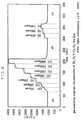
- Fig. 9 the vertical axis represents the sensor output (V) and the horizontal axis represents the time (min).
- the types and concentrations of the detection target gases are respectively denoted at positions corresponding vertically relative to the detection curve.
- Figs. 2, 6 and 8, to be referred to later employ the same method of graphic illustration as Fig. 9. Hence, these graphs are to be considered in comparison with each other.
- this sensor At a relatively high temperature range (normally, 450 °C), this sensor has substantially same sensitivity for CO and H 2 . On the other band, at a lower temperature range around 100 °C, the sensor is capable of detecting CO and H 2 distinctly from each other. However, if the sensor is maintained at such low temperature for an extended period of time, there occurs reduction in the sensor sensitivity due to e.g. ambient moisture. Therefore, it is necessary to periodically heat the sensor so as to remove therefrom water vapor which tends to be adsorbed by the sensor under the low temperature. Then, for effecting CO detection in an environment in which both CO and H 2 are present, the ambient temperature of the sensor is alternatively elevated and lowered periodically, and the sensor is capable of selectively detecting CO when the temperature is low.
- the sensor provides a jagged detection curve as shown in Fig. 9.
- the detection value at the bottom between the adjacent 'hills' of the jagged curve is used as the effective CO detection value for each gas concentration.
- the 'high concentration range' here denotes a gas concentration range exceeding 500 ppm approximately.
- the sensitivity of the sensor becomes poorer.
- the 'low concentration range' here denotes a range below 50 ppm approximately.
- the sensor outputs values of small magnitudes, hence, the sensor sensitivity is poor in such low concentration ranges too.
- a primary object of the present invention is to provide a carbon monoxide sensor capable of solving the above problems of the conventional CO sensors.
- the gas detecting portion is comprised mainly of metal oxide represented by a following Formula 1; Cu 1-x Bi x O y (0 ⁇ x ⁇ 1: y is determined by x). (this composition will be referred to as Composition 1 hereinafter)
- the present inventors has discovered that the sensor including a gas detecting portion comprised mainly of the material having the above-described composition provides a resistant value which varies in good response to CO concentration variation as well as superior selectivity for CO against H 2 .
- This sensor can be used continuously in a relatively high temperature range where the sensor may he protected against disturbing effect of e.g. ambience moisture. Then, this sensor is capable of effecting CO detection without necessitating periodical and alternate ambience temperature lowering and elevating operations. Also, with this sensor, the output resistance value of its gas detecting portion increases substantially linearly in response to increase in CO concentration, and this resistance variation is of sub magnitude that it is still detectable at the low concentration range of 50 ppm or lower. Moreover, the sensor response speed is superior to that of the convention using tin oxide. Further, this sensor has origin reversibility (i.e. the ability to return to the origin immediately with disappearance of CO).
- the gas detecting portion is provided in the form of a thin film comprised mainly of a metal oxide represented by a following Formula 2, the film having a thickness smaller than 1 ⁇ m (this composition will be referred to as Composition 2 hereinafter).
- Composition 2 this composition will be referred to as Composition 2 hereinafter.
- the present inventors have discovered that the sensor including a gas detecting portion comprised mainly of the material having the above-described composition provides a resistance value which varies in good response to CO concentration variation as well as superior selectivity for CO against H 2 . Moreover, by forming the film in the thickness of 1 ⁇ m or smaller, the sensitivity for CO as well as the selectivity against H 2 may be further improved. In this respect, in the case of zero substitution by Y, in comparison with the presence of at least some substitution by Y, the sensor sensitivity for CO is lowest, and so is the selectivity for CO against H 2 .
- the output resistance value of its gas detecting portion increases substantially linearly in response to increase in CO concentration, and this resistance variation is detectable at the low concentration range of 50 ppm or lower. Moreover, the sensor response speed is superior to that of the convention using tin oxide.
- the gas detecting portion is comprised mainly of copper oxide semiconductor added with a metal compound belonging in group 2A of the periodic table (this composition will be referred to as Composition 3 hereinafter).
- this sensor too does not require the periodic temperature lowering and elevating operations. And, this sensor is capable also of selectively detecting CO against H 2 even in the relatively high temperature condition, thus achieving sufficient CO sensitivity at such high temperature range as well as at the low concentration range. Moreover, this sensor has good origin reversibility to return to its origin when CO becomes absent.
- the metal compound belonging in the group 2A to be added to the copper oxide semiconductor comprises at least one kind of alkaline earth metal selected from the group consisting of barium, strontium and calcium.
- Such compounds can effectively restrict the H 2 sensitivity of the copper oxide semiconductor.
- these group-2A metal compounds are present in the gas detecting portion as more than one phase of oxide compound with oxide, hydroxide, carbonate or copper.
- the composition of the group-2A metal compound to be added to the copper oxide semiconductor used in the gas detecting portion is such that the metal compound is present in an equivalent went ratio: 0 ⁇ d / Cu ⁇ 2.0, where 'd' is an equivalent weight of the group 2A metal contained in the metal compound relative to copper.
- the detecting portion is preferably provided as a thin film formed on a substrate.
- the gas detecting portion may be fabricated by the well-known sintering method.
- the gas detecting portion is sintered on the substrate, thereby to affix the gas detecting portion on the substrate simultaneously with the sintering process.
- the gas detecting portion may be sintered in advance and then he affixed to the substrate.
- binder material exerting no effect on the sensor sensitivity may be used in the material for forming the gas detecting portion. Such addition of binder material will he userful and effective also in the thin film type construction described hereinbefore.
- the gas detecting portion further includes a catalyst layer for preventing non-target gas (i.e. any other gas than the target CO gas) from reaching the gas detecting portion.
- a catalyst layer for preventing non-target gas (i.e. any other gas than the target CO gas) from reaching the gas detecting portion.
- the gas detecting portion may be heated by heating means such as a heater attached to the substrate.
- heating means such as a heater attached to the substrate.
- the heating may be effected so as to adjust and maintain the gas detecting portion at a predetermined temperature.
- the heating means may be embedded within the substrate.
- the heater may he provided in the form of a layer attached to the substrate or affixed to one side of the substrate.
- the heating means may be adapted to heat the periphery of the substrate.
- a carbon monoxide sensor to which the present invention relates, generally includes a gas detecting portion and at least one pair of electrodes electrically connected with the gas detecting portion. More particularly, as shown in Fig. 1, the sensor includes a gas detecting portion 1 provided in the form of a bulk or film comprised of a material having a predetermined composition according to the invention and pairs of electrodes 2 and 3 attached to a surface of the gas detecting portion 1. In operation, the sensor detects carbon monoxide through detection of an electric property between these electrodes pairs. Usually, the paired electrodes 2 are used for applying electric current, while the other paired electrodes 3 are used for detecting developed electric potential.
- the gas detecting portion 1, which is the main component of this carbon monoxide sensor, is formed on a substrate 4, which in turn includes a heater for heating the gas detecting portion 4.
- the gas detecting portion 1 is provided in the form of a bulk-like portion, the so-called sintering method may be employed. Then, powderly starting materials are mixed in a predetermined mixture ratio and then sintered together for obtaining the target material. Further, in fabricating this gas detecting portion, by additionally using binder material which does not affect the sensor sensitivity, the physical strength of the sintered product may be improved advantageously.
- the gas detecting portion 1 is provided in the form of a thin film
- any of the chemical vapor deposition method such as the heat CVD, plasma CVD and laser CVD method, or physical vapor deposition method such as vacuum vapor deposition method, sputtering method and laser ablation method may be implemented.
- the Composition 2 of the invention where the film thickness is to be controlled, such method as cited above may be employed.
- binder material not affecting the sensor sensitivity may be additionally used for increasing the physical strength of the gas detecting portion 1.
- the present invention proposes the following three kinds of compositions, namely, the Composition 1 of Cu 1-x Bi x O y (0 ⁇ x ⁇ 1: y is determined by x), Composition 2 of Bi 2 Sr 2 (Ca a Y b ) Cu 2 O 8+c (0 ⁇ a ⁇ 1, 0 ⁇ b ⁇ 1) and the Composition 3 of copper oxide semiconductor added with a metal compound belonging in the group 2A of the periodic table.
- the melting point of the raw material mixture obtained by the sintering becomes lower.
- the gas detecting portion including a high ratio of Bi 2 O 3 be sintered at a relatively low temperature.
- the crystal structure of the gas detecting portion obtained as described above was analyzed through the X-ray diffraction analysis. According to the analysis, when the addition amount of Bi is 0.05 or less, no X-ray diffraction detection was possible due to the small amount of Bi and the single phase of CuO was detected. On the other hand, when the amount was within a range between 0.05 and 2.0, phases of CuO, CuBi 2 O 4 and a trace amount of Bi 2 O 3 were detected. Further, in case the amount was greater than 2.0, phases of CuBi 2 O 4 and Bi 2 O 3 were detected.
- the electrodes 2, 3 were formed of platinum, as shown in Fig. 1.
- Target gas for detection was obtained by mixing CO and H 2 in predetermined concentrations with air. Further, there was used another target gas including a predetermined amount of water vapor in addition to the above. These target gases had an oxygen concentration of about 20% and was dry or having a moisture of 1, 1.5%.
- Table 1 shows the results of measurement of the sensitivity of the gas detecting portion in which the ratio of Bi (i.e. the value of x in formula 3) was varied for the gas having 1000 ppm CO concentration and 1000 ppm H 2 concentration.
- sensor sensitivity x sensor sensitivity CO(1000ppm) H 2 (1000ppm) 0 1.06 1.60 0.001 1.57 1.23 0.002 1.58 1.12 0.005 1.51 1.10 0.01 1.56 1.14 0.02 1.48 1.08 0.04 1.60 1.11 0.05 1.50 1.32 0.667 1.29 1.20 0.8 1.30 1.20 1.0 1.57 1.40
- the sensor having the gas detecting portion comprised solely of copper oxide has lower sensitivity for CO than for H 2 but that the sensors having the gas detecting portions comprised of oxide containing Bi and bismuth oxide both have high sensitivity for CO. Further, if the effect of e.g. moisture is considered, it is preferred that 'x' is greater than 0 (excluding 0 per se) and smaller than 0.5.
- Fig. 2 illustrates the response and the dependence of CO concentration and H 2 concentration of the resistance value variation of the sensor using a gas detecting portion having the ratio of bismuth used, i.e. Bi/CuO (Formula 3), of 4/96.
- the measurement was conducted on target gas having water vapor concentration of 1% at 300°C. In this measurement, no periodic heating/cooling was done.
- the senor of the invention is capable of detecting CO without necessitating any periodic heating operation and provides good sensitivity at the high gas concentration range (i.e. the detection value varies in proportion to the logarithmic value of the gas concentration) and also good sensitivity (resistance value variation) at the relatively low gas concentration range.
- Fig. 3 illustrates the response and the dependence on CO concentration and H 2 concentration of the resistance value variation of the sensor using a gas detecting portion having the ratio of bismuth use, i.e. x in Formula 3 ranging between 0 and 0.01.
- the measurement was conducted on target gas under dry condition at 300°C. In this measurement, no periodic heating/cooling was done.
- the results show that the sensor including the gas detecting portion using CuO alone has high sensitivity for H 2 , but the sensor including the gas detecting portion containing also Bi can achieve the intended object of the present invention.
- the target gas used in this measurement had a temperature of 300°C and an absolute water vapor concentration of 1.5%.
- the sensor using the gas detecting portion according to the invention has higher sensitivity for CO than for H 2 and this sensitivity S increases with increase in the gas concentration and also that the further sensor using a gas detecting portion not containing Bi has higher sensitivity for H 2 than for CO thus not suitable for achieving the object of the present invention.
- this sensor of the invention its sensitivity for CO is higher than that for H 2 in the relatively high temperature range where removal of moisture is not necessary, so that this sensor can maintain sufficient gas selectivity for CO at such high temperature range.
- the oxide compound for forming the gas detecting portion 1 is obtained according to the following procedure.
- Precursor material is obtained from raw material mixture including the elements shown in Formula 2 of the gas detecting portion 1 in a predetermined ratio.
- Bi:Sr:Ca:Y:Cu are Bi 2 O 3 , SrCO 3 , CaCO 3 , Y 2 O 3 , CuO and so on
- the value 'b' was set to: 1, 0.8, 0.6, 0.4, 0.2, 0.1, 0.05, 0.01, 0.005 and 0.
- the obtained precursor material is subjected to a preliminary baking and preliminary sintering step, whereby preliminary sintered product is obtained.
- the precursor material is sintered at a temperature (780 to 800 °C approximately) lower than a main sintering step, preferably for 48 hours. Then, the preliminary sintered product thus obtained is pulverized to adjust it particle diameter of 1 to 20 ⁇ m approximately.
- the resultant preliminary sintered material is subjected to at least two cycles of the main sintering step in a noble gas or carbon gas atmosphere containing 20% or more of oxygen at 810 to 850°C, whereby raw material comprised mainly of metal oxide represented by a following Formula 2 and having 2212 phase crystal structure is obtained;.
- the material is pulverized to adjust its particle diameter to 1 to 20 ⁇ m.
- the noble gas argon gas, helium gas or carbon gas is employed.
- the main sintering step is done for at least two cycles at the above-specified temperature range for 24 hours or more.
- the main sintering step is done at least two cycles in argon gas atmosphere containing 20% or more oxygen at a temperature range of 820 to 845°C for 30 hours or longer.
- the raw material to be used for a film forming step as follows may be obtained. That is, in case the laser ablation method is employed as is the case with this example, the target of the laser ablation may be obtained.
- a film forming method such as the laser ablation method is implemented for obtaining a non-crystalline film having the above-described composition on the substrate 4.
- the thickness of the film is set to be 1 ⁇ m or smaller.
- the non-crystalline film formed on the substrate is heated at 830 to 950°C for 20 to 60 minutes.
- the gas detecting portion 1 comprised mainly of the material whose composition satisfies the above formula and which has the 2212 phase crystalline structure.
- the electrodes 2, 3 are attached, and the substrate forming the bottom of the gas detecting portion 1 is used as the heating substrate. Further, if necessary, an oxidizing catalyst layer carrying platinum is attached to the surface side of the gas detecting portion 1.
- alumina or the like may be employed as the base material of the oxidizing catalyst layer.
- Target gas employed was obtained by mixing air with predetermined concentrations of CO, H 2 and methane and also with a predetermined amount of water vapor.
- the oxygen concentration and the moisture content of this gas were adjusted to about 20% and about 1.5%, respectively.
- a predetermined electric potential was applied to the substrate of the gas sensor element thereby to heat and maintain the gas detecting portion 1 to a predetermined temperature range around 400°C.
- the sensor was brought into contact with the target gas and an electric resistance developed between the opposed electrodes was measured. Then, the relationship between the variation of this resistance and respective concentrations of the gas was determined.
- the gas sensitivity S was determined by the foregoing same expression (Rg/Rair).
- Fig. 5 illustrates the sensitivity values for the respective gas concentrations with varying the substitution amount by Y relative to Ca in the Composition 2.
- Fig. 5(a) shows the case in which the substitution amount was limited to relatively small values.
- Fig. 5(b) shows the case in which the substitution amount was varied from zero to 100%.
- the Y substitution amount be greater than 0.01 and smaller than 1 (more preferably, greater than 0.8 and smaller than 1).
- Fig. 6 illustrates the response and dependence on CO concentration and H 2 concentration of the resistance value variation of the sensor using the gas detecting portion having a composition of 100% substitution by Y. In this measurement, no periodic heating/cooling was done.
- the senor of the invention is capable of detecting CO without necessitating any periodic heating operation and provides good quantitative performance at the high gas concentration range (i.e. the detection value varies in proportion to the logarithmic value of the gas concentration) and also good sensitivity (resistance value variation) at the relatively low gas concentration range.
- the horizontal axis represents the film thickness ( ⁇ m) and the vertical axis represents the sensitivity S.
- the sensitivity depends on the film thickness.
- the film thickness is smaller than 1 ⁇ m, the CO sensitivity is significantly increased, so that the selectivity against H 2 may be maintained sufficiently.
- the present inventors believe that this phenomenon is attributable to increase of the effect of CO on the resistance variation of the gas detects portion in association with decrease in the film thickness.
- the lower limit of the film thickness is the detestable limit of electric resistance value. The same tendency was observed also in the cases having different substitution amounts.
- the gas detecting portion As material for forming the gas detecting portion, commercially available CuO powder, as Cu source, was employed, and to this, powder of a compound of metal belonging in the group 2A of the periodic table, preferably, an alkaline earth metal compound, more preferably, CaCO 3 , SrCO 3 , BaCO 3 , is added in a predetermined ratio. Then, this mixture is heated at 600 to 1000°C to be rendered into a sintered product to be used as the gas detecting portion. The sintering is effected, preferably, on the substrate. Then, on this gas detecting portion, the electrodes are disposed with a predetermined inter-distance.
- an alkaline earth metal compound more preferably, CaCO 3 , SrCO 3 , BaCO 3
- the raw material of the gas detecting portion commercially available CuO powder of high purity was employed as the Cu source, and BaCO 3 was used as the Ba compound raw material. And, these materials were mixed to obtain a predetermined Ba/Cu ratio. Then, the mixture was heated at 600 to 960°C, whereby the gas detecting portion was obtained as the sintered product.
- the equivalent weight ratio of Ba/Cu was varied in the range of 0 to 2.
- the equivalent ratios of Ba/Cu actually used were 0.0005, 0.001, 0.005, 0.01, 0.03, 0.05, 0.11, 0.67, 1.0 and 2.0.
- a system with no addition of Ba compound was also studied.
- the gas detecting portions thus obtained were analyzed by the X-ray diffraction analysis. The analysis revealed that the crystal phase of the sintered products were comprised mainly of CuO and BaCuO 2 and also that BaCO 3 was also observed in the case of those having a large addition amount of Ba or treated under low temperature.
- Ca/Cu type gas detecting portion was fabricated under the same conditions as the embodiment 1 of Composition 3, except that CaCO 3 was employed as the Ca compound raw material in this case.
- the sintering temperature was between 600 and 960°C.
- the equivalent weight ratios of Ca/Cu actually used were 0.0005, 0.001, 0.005, 0.01, 0.03, 0.05, 0.1, 0.2, 0.5 and 2.0.
- a system with no addition of Sr compound was also studied.
- the gas detecting portions thus obtained were analyzed by the X-ray diffraction analysis. The analysis revealed that the crystal phase of the sintered products were comprised mainly of CuO, Ca 2 CuO 3 and also that CaCO 3 phase was also observed in the case of those having a large addition amount of Sr or treated under low temperature.
- Sr/Cu type gas detecting portion was fabricated under the same conditions as the embodiment 1 of Composition 3, except that SrCO 3 was employed as the Sr compound raw material in this case.
- the equivalent weight ratios of Sr/Cu actually used were 0.0005, 0.001, 0.005, 0.01, 0.03, 0.05, 0.11, 0.5, 1.0 and 2.0.
- a system with no addition of Sr compound was also studied
- the gas detecting portions thus obtained were analyzed by the X-ray diffraction analysis. The analysis revealed that the crystal phase of the sintered products were comprised mainly of CuO, CuSrO 2 , Cu 2 SrO 3 and also that SrCO 3 phase was also observed in the case of those having a large addition amount of Sr or treated under low temperature.
- the lower limit of the addition amount of the 2A group metal compound was 0.0005 (0.05%) in the disclosed embodiment.
- this limit was imposed due to the use of high-purity copper oxide (99.99%) readily available at present. Hence, it is understood that the limit may be still lower.
- Target gas for detection was obtained by mixing CO and H 2 in predetermined concentrations with air and by adding thereto a predetermined amount of water vapor.
- the gas had an oxygen concentration of about 10% and a volume ratio of water vapor of about 10% (about 80g/m 3 if converted into the absolute humidity).
- the optimal temperature range is between 300 and 350°C.
- Table 2 shows the results of measurements of the sensitivities of the gas sensor elements obtained in the embodiments 1 through 3 of Composition 3 described above for the target gas containing either CO or H 2 .
- group 2A metal /Cu equivalent weight ratio Ba Ca Sr CO sensitivity H 2 sensitivity CO sensitivity H 2 sensitivity CO sensitivity H 2 sensitivity 0.0000 1.36 1.78 1.36 1.78 1.36 1.78 0.0005 1.59 1.19 1.57 1.41 1.44 1.32 0.001 1.39 1.11 1.52 1.36 1.30 1.10 0.005 1.11 1.06 1.15 1.13 1.22 1.07 0.01 1.22 1.12 1.04 1.02 1.15 1.05 0.03 1.02 1.00 1.05 1.01 1.17 1.02 0.05 1.24 1.00 1.05 1.02 1.18 1.00 0.1 1.20 1.02 1.04 1.00 - - 0.111 - - - - 1.20 1.03 0.2 - - 1.08 1.00 - - 0.5 - - 1.27 1.00 1.14 1.02 0.67 1.44 1.05 - - - -
- the colomn: "Ba” shows the dependence of the sensitivity S of the Ba type copper oxide sensor element of the embodiment 1 of Composition 3 on the addition amount of Ba, for the target gas containing 1000 ppm of CO and the target gas containing 1000 ppm of H 2 .
- the column: "Ca” shows the dependence of the sensitivity S of the Ca type copper oxide sensor element of the embodiment 2 of Composition 3on the addition amount of Ca , for the target gas containing 1000 ppm of CO and the target gas containing 1000 ppm of H 2 .
- the column: Sr' shows the dependence of the sensitivity S of the Ca type copper oxide sensor element of the third composition example 3 on the addition amount of Sr, for the target gas containing 1000 ppm of CO and the target gas containing 1000 ppm of H 2 .
- Fig. 8 illustrates the response characteristics, corresponding to Fig. 9, of the sintered product having the Ca/Cu ratio of 1/9 at the water vapor concentration of 1% at 300°C. In this case too, in the measurement, no periodical heating/cooling operation was effected.
- this product is capable of detecting CO without necessitating the periodical heating/cooling operation And, this product has good quantitative performance at the high gas concentration range (the detection value varies in proportion to the logarithmic value of the gas concentration) as well as good sensitivity (resistance value variation) in the relatively low concentration range.
Abstract
Description
| sensor sensitivity | ||
| x | sensor sensitivity | |
| CO(1000ppm) | H2(1000ppm) | |
| 0 | 1.06 | 1.60 |
| 0.001 | 1.57 | 1.23 |
| 0.002 | 1.58 | 1.12 |
| 0.005 | 1.51 | 1.10 |
| 0.01 | 1.56 | 1.14 |
| 0.02 | 1.48 | 1.08 |
| 0.04 | 1.60 | 1.11 |
| 0.05 | 1.50 | 1.32 |
| 0.667 | 1.29 | 1.20 |
| 0.8 | 1.30 | 1.20 |
| 1.0 | 1.57 | 1.40 |
Between the two cycles of the main sintering step, the material is pulverized to adjust its particle diameter to 1 to 20 µm. Further, as the noble gas, argon gas, helium gas or carbon gas is employed. And, the main sintering step is done for at least two cycles at the above-specified temperature range for 24 hours or more. In this case, preferably, the main sintering step is done at least two cycles in argon gas atmosphere containing 20% or more oxygen at a temperature range of 820 to 845°C for 30 hours or longer.
as the gas detecting portion. The sintering is effected, preferably, on the substrate. Then, on this gas detecting portion, the electrodes are disposed with a predetermined inter-distance.
The equivalent weight ratios of Ca/Cu actually used were 0.0005, 0.001, 0.005, 0.01, 0.03, 0.05, 0.1, 0.2, 0.5 and 2.0. For comparison, a system with no addition of Sr compound was also studied. The gas detecting portions thus obtained were analyzed by the X-ray diffraction analysis. The analysis revealed that the crystal phase of the sintered products were comprised mainly of CuO, Ca2CuO3 and also that CaCO3 phase was also observed in the case of those having a large addition amount of Sr or treated under low temperature.
The equivalent weight ratios of Sr/Cu actually used were 0.0005, 0.001, 0.005, 0.01, 0.03, 0.05, 0.11, 0.5, 1.0 and 2.0. For comparison, a system with no addition of Sr compound was also studied The gas detecting portions thus obtained were analyzed by the X-ray diffraction analysis. The analysis revealed that the crystal phase of the sintered products were comprised mainly of CuO, CuSrO2, Cu2SrO3 and also that SrCO3 phase was also observed in the case of those having a large addition amount of Sr or treated under low temperature.
| group 2A metal /Cu equivalent weight ratio | Ba | Ca | Sr | |||
| CO sensitivity | H2 sensitivity | CO sensitivity | H2 sensitivity | CO sensitivity | H2 sensitivity | |
| 0.0000 | 1.36 | 1.78 | 1.36 | 1.78 | 1.36 | 1.78 |
| 0.0005 | 1.59 | 1.19 | 1.57 | 1.41 | 1.44 | 1.32 |
| 0.001 | 1.39 | 1.11 | 1.52 | 1.36 | 1.30 | 1.10 |
| 0.005 | 1.11 | 1.06 | 1.15 | 1.13 | 1.22 | 1.07 |
| 0.01 | 1.22 | 1.12 | 1.04 | 1.02 | 1.15 | 1.05 |
| 0.03 | 1.02 | 1.00 | 1.05 | 1.01 | 1.17 | 1.02 |
| 0.05 | 1.24 | 1.00 | 1.05 | 1.02 | 1.18 | 1.00 |
| 0.1 | 1.20 | 1.02 | 1.04 | 1.00 | - | - |
| 0.111 | - | - | - | - | 1.20 | 1.03 |
| 0.2 | - | - | 1.08 | 1.00 | - | - |
| 0.5 | - | - | 1.27 | 1.00 | 1.14 | 1.02 |
| 0.67 | 1.44 | 1.05 | - | - | - | - |
| 1.0 | 1.66 | 1.03 | - | - | 1.13 | 1.07 |
| 2.0 | 1.50 | 1.00 | 1.07 | 1.00 | 1.11 | 1.02 |
Claims (11)
- A carbon monoxide sensor including a gas detecting portion and at least a pair of electrodes, wherein the gas detecting portion is comprised mainly of metal oxide represented by a following Formula 1;
- A carbon monoxide sensor including a gas detecting portion and at least a pair of electrode, wherein the gas detecting portion is provided in the form of a film comprised mainly of a metal oxide represented by a following Formula 2, the film having a thickness smaller than 1 µm;
- A carbon monoxide sensor a carbon monoxide sensor including a gas detecting portion and at least one pair of electrodes, wherein the gas detecting portion is comprised mainly of copper oxide semiconductor added with a metal compound belonging in group 2A of the periodic table.
- A carbon monoxide sensor as claimed in claim 3, wherein the metal compound belonging in the group 2A to be added to the copper oxide semiconductor comprises more than one kind of alkaline earth metal selected from the group consisting of barium, strontium and calcium.
- A carbon monoxide sensor as claimed in claim 3 or 4, wherein the group-2A metal compounds are present in the gas detecting portion as more than one phase of oxide compound with oxide, hydroxide, carbonate or copper.
- A carbon monoxide sensor as claimed in any one of claims 3 through 5, wherein ,the composition of the group 2A metal compound to be added to the copper oxide semiconductor used in the gas detecting portion is such that the metal compound is present in an equivalent weight ratio: 0<d / Cu≦2.0, where 'd' is an equivalent weight of the group 2A metal contained in the metal compound relative to copper.
- A carbon monoxide sensor as claimed in any one of claims 1 and 3 through 6, wherein the gas detecting portion is provided in the form of a thin film formed on a substrate.
- A carbon monoxide sensor as claimed in any one of claims 1 and 3 through 6, wherein the gas detecting portion is formed by the sintering method.
- A carbon monoxide gas sensor as claimed in claim 7 or 8, wherein the gas detecting portion further includes binder which does not affect the CO sensitivity of the gas detecting portion.
- A carbon monoxide gas sensor as claimed in claim any one of claims 1 through 9, wherein the gas detecting portion further includes a catalyst layer for preventing non-CO gas from reaching the gas detecting portion.
- A carbon monoxide gas sensor as claimed in claim any one of claims 1 through 10, wherein the gas detecting portion is heatable by a heater.
Applications Claiming Priority (10)
| Application Number | Priority Date | Filing Date | Title |
|---|---|---|---|
| JP169031/96 | 1996-06-28 | ||
| JP16902996 | 1996-06-28 | ||
| JP169030/96 | 1996-06-28 | ||
| JP16903096 | 1996-06-28 | ||
| JP169029/96 | 1996-06-28 | ||
| JP16903196 | 1996-06-28 | ||
| JP262683/96 | 1996-10-03 | ||
| JP8262683A JP2996921B2 (en) | 1996-06-28 | 1996-10-03 | Carbon monoxide detection sensor |
| JP08909097A JP3669807B2 (en) | 1996-06-28 | 1997-04-08 | Carbon monoxide detection sensor |
| JP89090/97 | 1997-04-08 |
Publications (2)
| Publication Number | Publication Date |
|---|---|
| EP0816844A2 true EP0816844A2 (en) | 1998-01-07 |
| EP0816844A3 EP0816844A3 (en) | 1998-01-28 |
Family
ID=27525396
Family Applications (1)
| Application Number | Title | Priority Date | Filing Date |
|---|---|---|---|
| EP97110455A Withdrawn EP0816844A3 (en) | 1996-06-28 | 1997-06-26 | Carbon monoxide sensor |
Country Status (5)
| Country | Link |
|---|---|
| US (1) | US5980833A (en) |
| EP (1) | EP0816844A3 (en) |
| KR (1) | KR980003568A (en) |
| CN (1) | CN1174992A (en) |
| TW (1) | TW353141B (en) |
Families Citing this family (9)
| Publication number | Priority date | Publication date | Assignee | Title |
|---|---|---|---|---|
| US6319473B1 (en) * | 1998-06-16 | 2001-11-20 | Figaro Engineering, Inc. | Co sensor and its fabrication |
| US20090101501A1 (en) * | 2007-10-17 | 2009-04-23 | Tao Xiao-Ming | Room temperature gas sensors |
| CN102507657A (en) * | 2011-11-08 | 2012-06-20 | 中南大学 | Method for preparing high-sensitivity bismuth-doped tin dioxide sensing material |
| CN103529173A (en) * | 2013-10-24 | 2014-01-22 | 沈阳添瀛通用设备有限公司 | Carbon monoxide sensor |
| CN104391025B (en) * | 2014-11-19 | 2017-01-18 | 上海纳米技术及应用国家工程研究中心有限公司 | Preparation method of electrochemical carbon oxide gas sensor electrode |
| DE102017208418A1 (en) * | 2017-05-18 | 2018-11-22 | Robert Bosch Gmbh | Method for producing a nanocrystalline, gas-sensitive layer structure, corresponding nanocrystalline, gas-sensitive layer structure, and gas sensor with a corresponding nanocrystalline, gas-sensitive layer structure |
| US11686698B2 (en) * | 2018-05-14 | 2023-06-27 | Canon Kabushiki Kaisha | Reducing gas detection material and reducing gas detection sensor |
| CN109148593B (en) * | 2018-07-16 | 2020-09-01 | 复旦大学 | Ternary p-type CuBi2O4Thin film transistor and preparation method thereof |
| CN111289582B (en) * | 2020-03-26 | 2022-03-11 | 微纳感知(合肥)技术有限公司 | MEMS gas sensor, array thereof, gas detection method and preparation method |
Citations (5)
| Publication number | Priority date | Publication date | Assignee | Title |
|---|---|---|---|---|
| DE3024449A1 (en) * | 1976-10-26 | 1982-01-28 | Robert Bosch Gmbh, 7000 Stuttgart | Semiconductor sensor for determn. of oxygen in exhaust gas - consists cerium di:oxide doped with other oxide, esp. magnesia or alumina |
| US5252949A (en) * | 1991-08-28 | 1993-10-12 | Hughes Aircraft Company | Chemical sensor for carbon monoxide detection |
| US5346671A (en) * | 1993-01-26 | 1994-09-13 | Fci - Fiberchem, Inc. | Specific and reversible carbon monoxide sensor |
| US5351029A (en) * | 1991-01-15 | 1994-09-27 | Robert Bosch Gmbh | Sensor for determining carbon monoxide |
| US5362651A (en) * | 1992-07-27 | 1994-11-08 | Ford Motor Company | Carbon monoxide selective sensor and method of its use |
Family Cites Families (6)
| Publication number | Priority date | Publication date | Assignee | Title |
|---|---|---|---|---|
| JPS5343320A (en) * | 1976-09-30 | 1978-04-19 | Aisin Seiki Co Ltd | Outrigger for truck-mounted crane |
| DE2648373C2 (en) * | 1976-10-26 | 1986-01-02 | Robert Bosch Gmbh, 7000 Stuttgart | Semiconductors for sensors for determining the content of oxygen and / or oxidizable components in exhaust gases |
| JP2918394B2 (en) * | 1992-05-29 | 1999-07-12 | 大阪瓦斯株式会社 | Nitrogen oxide detection sensor |
| US5382341A (en) * | 1992-09-10 | 1995-01-17 | Aroutiounian; Vladimir M. | Method of making smoke detector |
| JP2882974B2 (en) * | 1993-06-30 | 1999-04-19 | 財団法人国際超電導産業技術研究センター | Nitrogen oxide detection sensor |
| CA2198049A1 (en) * | 1996-02-21 | 1997-08-21 | Shuzo Kudo | Method of manufacturing nitrogen oxide sensor, and nitrogen oxide sensor manufactured by the method and material therefor |
-
1997
- 1997-06-26 EP EP97110455A patent/EP0816844A3/en not_active Withdrawn
- 1997-06-27 TW TW086109030A patent/TW353141B/en active
- 1997-06-27 KR KR1019970028472A patent/KR980003568A/en not_active Application Discontinuation
- 1997-06-27 US US08/883,785 patent/US5980833A/en not_active Expired - Lifetime
- 1997-06-28 CN CN97112594A patent/CN1174992A/en active Pending
Patent Citations (5)
| Publication number | Priority date | Publication date | Assignee | Title |
|---|---|---|---|---|
| DE3024449A1 (en) * | 1976-10-26 | 1982-01-28 | Robert Bosch Gmbh, 7000 Stuttgart | Semiconductor sensor for determn. of oxygen in exhaust gas - consists cerium di:oxide doped with other oxide, esp. magnesia or alumina |
| US5351029A (en) * | 1991-01-15 | 1994-09-27 | Robert Bosch Gmbh | Sensor for determining carbon monoxide |
| US5252949A (en) * | 1991-08-28 | 1993-10-12 | Hughes Aircraft Company | Chemical sensor for carbon monoxide detection |
| US5362651A (en) * | 1992-07-27 | 1994-11-08 | Ford Motor Company | Carbon monoxide selective sensor and method of its use |
| US5346671A (en) * | 1993-01-26 | 1994-09-13 | Fci - Fiberchem, Inc. | Specific and reversible carbon monoxide sensor |
Also Published As
| Publication number | Publication date |
|---|---|
| TW353141B (en) | 1999-02-21 |
| KR980003568A (en) | 1998-03-30 |
| CN1174992A (en) | 1998-03-04 |
| EP0816844A3 (en) | 1998-01-28 |
| US5980833A (en) | 1999-11-09 |
Similar Documents
| Publication | Publication Date | Title |
|---|---|---|
| KR100337102B1 (en) | Sensor for detecting nitrogen oxide | |
| US4314996A (en) | Oxygen sensor | |
| US4794323A (en) | Multifunctional ceramic sensor | |
| Coles et al. | Selectivity studies on tin oxide-based semiconductor gas sensors | |
| US5942676A (en) | Sensor for the detection of combustible gases | |
| US5397541A (en) | Thin film oxygen sensor | |
| US5427740A (en) | Tin oxide gas sensors | |
| US5980833A (en) | Carbon monoxide sensor | |
| Gerblinger et al. | High temperature oxygen sensor based on sputtered cerium oxide | |
| EP0197629B1 (en) | Alcohol selective gas sensor | |
| JP3845741B2 (en) | Nitrogen oxide detection method and sensor element for nitrogen oxide detection | |
| US4964016A (en) | Multi-layer ceramic capacitors having, as the conductive elements therein, layers of perovskites containing oxygen and nitrogen | |
| US6513364B1 (en) | Hydrogen sensor | |
| KR100189041B1 (en) | Sensor for determining carbon monoxide | |
| US5051718A (en) | Thermistor element and gas sensor using the same | |
| US5734091A (en) | Method of manufacturing nitrogen oxide sensor, and nitrogen oxide sensor manufactured by the method and material therefor | |
| EP0375013B1 (en) | Solid-state sensor for determining hydrogen and/or nox concentration, and the method for its preparation | |
| WO2020090489A1 (en) | Thermistor sintered body and temperature sensor element | |
| JP3075070B2 (en) | Carbon monoxide gas sensor | |
| JP4627671B2 (en) | CO2 sensor | |
| US5864148A (en) | High-temperature gas sensor | |
| US5362651A (en) | Carbon monoxide selective sensor and method of its use | |
| JP2996921B2 (en) | Carbon monoxide detection sensor | |
| JP3314509B2 (en) | NOx gas sensing semiconductor and method of manufacturing the same | |
| US5863503A (en) | Nitrogen oxide detecting sensor and method of manufacturing the same |
Legal Events
| Date | Code | Title | Description |
|---|---|---|---|
| PUAI | Public reference made under article 153(3) epc to a published international application that has entered the european phase |
Free format text: ORIGINAL CODE: 0009012 |
|
| PUAL | Search report despatched |
Free format text: ORIGINAL CODE: 0009013 |
|
| AK | Designated contracting states |
Kind code of ref document: A2 Designated state(s): AT BE CH DE DK ES FI FR GB GR IE IT LI LU MC NL PT SE |
|
| AK | Designated contracting states |
Kind code of ref document: A3 Designated state(s): AT BE CH DE DK ES FI FR GB GR IE IT LI LU MC NL PT SE |
|
| 17P | Request for examination filed |
Effective date: 19980709 |
|
| RBV | Designated contracting states (corrected) |
Designated state(s): AT FI GB GR IT |
|
| REG | Reference to a national code |
Ref country code: DE Ref legal event code: 8566 |
|
| 17Q | First examination report despatched |
Effective date: 20000613 |
|
| GRAG | Despatch of communication of intention to grant |
Free format text: ORIGINAL CODE: EPIDOS AGRA |
|
| GRAG | Despatch of communication of intention to grant |
Free format text: ORIGINAL CODE: EPIDOS AGRA |
|
| GRAG | Despatch of communication of intention to grant |
Free format text: ORIGINAL CODE: EPIDOS AGRA |
|
| GRAH | Despatch of communication of intention to grant a patent |
Free format text: ORIGINAL CODE: EPIDOS IGRA |
|
| STAA | Information on the status of an ep patent application or granted ep patent |
Free format text: STATUS: THE APPLICATION IS DEEMED TO BE WITHDRAWN |
|
| 18D | Application deemed to be withdrawn |
Effective date: 20010918 |