EP0815960A1 - High pressure generator - Google Patents
High pressure generator Download PDFInfo
- Publication number
- EP0815960A1 EP0815960A1 EP97401472A EP97401472A EP0815960A1 EP 0815960 A1 EP0815960 A1 EP 0815960A1 EP 97401472 A EP97401472 A EP 97401472A EP 97401472 A EP97401472 A EP 97401472A EP 0815960 A1 EP0815960 A1 EP 0815960A1
- Authority
- EP
- European Patent Office
- Prior art keywords
- high pressure
- pump
- generator
- fluid
- frame
- Prior art date
- Legal status (The legal status is an assumption and is not a legal conclusion. Google has not performed a legal analysis and makes no representation as to the accuracy of the status listed.)
- Withdrawn
Links
Images


Classifications
-
- B—PERFORMING OPERATIONS; TRANSPORTING
- B08—CLEANING
- B08B—CLEANING IN GENERAL; PREVENTION OF FOULING IN GENERAL
- B08B3/00—Cleaning by methods involving the use or presence of liquid or steam
- B08B3/02—Cleaning by the force of jets or sprays
- B08B3/026—Cleaning by making use of hand-held spray guns; Fluid preparations therefor
-
- B—PERFORMING OPERATIONS; TRANSPORTING
- B08—CLEANING
- B08B—CLEANING IN GENERAL; PREVENTION OF FOULING IN GENERAL
- B08B2203/00—Details of cleaning machines or methods involving the use or presence of liquid or steam
- B08B2203/007—Heating the liquid
-
- B—PERFORMING OPERATIONS; TRANSPORTING
- B08—CLEANING
- B08B—CLEANING IN GENERAL; PREVENTION OF FOULING IN GENERAL
- B08B2203/00—Details of cleaning machines or methods involving the use or presence of liquid or steam
- B08B2203/02—Details of machines or methods for cleaning by the force of jets or sprays
- B08B2203/0205—Bypass pressure relief valves
Definitions
- the present invention relates to a high pressure generator especially for decontamination installations nuclear, chemical or bacteriological.
- high pressure generators that is to say devices capable of providing means sprinklers, such as spears, booms or showers, low or high pressure water added possibly a decontamination agent.
- An example of such a design is described in particular in patent FR-A-2,663,778 of the present applicant.
- This generator is in the form of a unit comprising heating means for carrying water at a temperature at which it can reach the state of steam, that is to say above 100 ° C, in normal atmospheric conditions, at least one tank of decontamination agent, a pump either to draw water in a natural resource, either to take it in a distribution network and finally pipes intended to be connected on the one hand to the water supply and on the other hand to the means of spraying.
- the venturi system also has disadvantages.
- the introduction of the decontamination agent in the flow takes place downstream heating means, the introduction of a cold fluid in a hot flow will cause a fall in the temperature. It is then impossible for the user to find out if decontamination was carried out at the temperature that it had predetermined at the start. In In some cases, this drop in temperature may prevent the decontamination to be carried out, in particular in the case of a bacteriological contamination.
- the concentration of decontamination agents that can be introduced into the water flow is limited. She is generally in the range of 0 to 15%. This concentration is sometimes insufficient to obtain a effective decontamination. It is then necessary to use much more corrosive products for achieve decontamination efficiency at such low concentrations.
- the aim of the present invention is therefore to propose a high pressure generator capable of supplying means a stream of water of selected pressure, added any decontaminating agent, and brought to a any temperature chosen, the agent concentration any decontaminant while the temperature of the flow leaving the fluid circuit can be kept at a constant value.
- Another object of the present invention is to provide a high pressure generator whose autonomy compared to existing generator is further improved and whose the size is reduced.
- the invention relates to a high generator pressure especially for mobile installation of nuclear, chemical or biological decontamination, of the type comprising, housed inside a frame and connected between them by suitable pipes, at least one pump low pressure suction, a high pressure pump and heating means, such as a boiler, said low pressure suction pump being connected to the inlet of disconnectable to a reserve of fluid, generally water, located outside of said frame to ensure the supply of fluid to the other elements so as to obtain, at the outlet of the heating means, a flow of pressurized fluid at a predetermined temperature adjustable, possibly added with a treatment such as a decontamination agent, this flow being projected onto things like people, materials or surfaces to be treated by means of spraying suitable as a ramp, lance or other, connected from removably on said generator at the output of the circuit fluid, characterized in that the high pressure pump is equipped with a second closable entry which opens in the fluid circuit, such as water, flowing at through said high pressure pump, this inlet of the pump is disconnectably connected to a
- the design of the generator allows to propose a new way introduction of the treatment agent who does not come substitute for existing means of introduction known but on the contrary supplement these known means of introduction of so as to enhance the versatility of this high generator pressure and autonomy while increasing its efficiency.
- the invention also relates to a mobile installation of nuclear, chemical or biological decontamination of the type comprising at least one motor vehicle fitted with a platform, characterized in that it further comprises at minus a high pressure generator of the aforementioned type.
- the high pressure generator object of the invention, is intended to supply spray means 27 such as ramp, lance or shower, known per se, a flow of fluid under a given pressure, at a predetermined temperature and optionally added with a treatment agent.
- the processing agent may have various compositions. So in the use in accordance with that described in the patent FR-A-2,663,778, this generator is especially designed to be integrated into a mobile decontamination station.
- the processing agent is a decontamination.
- a decontamination agent include sodium hyposulfite, liquids with very high concentration with neutral pH without substance caustic or harmful for the decontamination of the being human, etc.
- this generator can also be used in the field of agriculture during biological disasters that can happen on any territory, especially in the case of clouds insects that fall on crops or diseases which develop very quickly within these cultures. In this case, it is necessary to project for example a herbicide or insecticide which then constitutes the agent treatment.
- the high pressure generator can still be used in first aid equipment against for example hydrocarbon fires.
- the object of the invention is not to remove these means of introduction but to add to these two means an additional means of introduction at the level of the high pressure pump so as to leave the choice to the user enters these different possibilities, depending on the treatment agent to be screened, the characteristics (concentration, corrosion ...) of this agent and the type of decontamination, in particular the importance maintaining a constant temperature at the flow exit.
- the choice of an introduction of the treatment agent to level of the high pressure pump and not of the low pump pressure also eliminates the need for a low pump pressure resistant to highly corrosive products. he this results in a reduction in the cost of the low pressure pump and a simplification of its manufacture.
- the generator includes, analogous to the known high pressure generator, a frame 1 inside which are housed and interconnected, by suitable pipes, at least one pump low pressure suction 2, a high pressure pump 3 and heating means 4 such as a boiler.
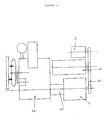
- the low pressure suction pump 2 is connected to the inlet of disconnectable to a reserve of fluid 5, generally water, located outside said frame 1, as shown in Figure 1 where the dashed line represents schematically the limits of the frame 1. It It should be noted that, generally, a battery of filters is interposed between the fluid reserve 5 and the pump 2.
- This suction pump 2 which is for example a pump centrifugal suction with a capacity of 70 liters / minute for a suction height of 5 meters at a distance of 20 meters, ensures the supply of fluid to other elements, namely high and medium pressure pump 3 heating 4 so as to obtain, at the outlet of the means heating 4, a pressurized fluid flow of adjustable predetermined temperature, if necessary added with a treatment agent.
- the fluid reserve 5 which is generally a reserve of water, can be a natural resource, river, pond, well, etc. or, in the case of an urban site, a network of traditional water distribution. It can also be constituted by a cistern, a tank or any other means possibly integrated into a vehicle.
- the heating means 4 can be consisting of a boiler known per se consisting of a boiler body inside which is arranged a coil, this coil allowing the circulation of the fluid inside said boiler body.
- This fluid is heated by means of burners, the control of which operation will be described below. Hot air as well product heats the fluid circulating in the coil.
- the fluid flow possibly added with a processing, is projected onto elements such as people, materials or surfaces to be treated by means 27 suitable for spraying such as a ramp, lance or other, removably connected to said generator in fluid circuit outlet.
- means 27 suitable for spraying such as a ramp, lance or other, removably connected to said generator in fluid circuit outlet.
- spraying means 27 upstream of the high pressure pump 3 on the connection between low pressure pump 2 and pump 3 high pressure.
- the treatment agent can therefore be introduced through a second inlet 28 of the high pressure pump 3.
- This second entry 28, closable leads into the circuit of the fluid, such as water, flowing through the pump 3 high pressure and is detachably connected to a storage reserve 29 for storing said treatment agent so to ensure the introduction of said treatment agent into the fluid flow.
- This storage reserve 29 can affect here again a large number of forms and come under tank, container or other form.
- the processing agent is introduced into the fluid circuit at the pump 3 high pressure, it is then very quickly mixed to the fluid, in particular before being introduced into the heating means and therefore the flow is at a constant temperature known when it reaches the means sprinkler 27.
- the heating means 4 are fitted at the outlet of a thermostat so as to regulate the temperature of said heating means 4 for maintaining constant flow temperature.
- the treatment agent is introduced under pressure and at a predetermined flow rate inside the high pressure pump 3.
- This flow is regulated by via a metering pump 6, such as a pump electric membrane, preferably self-priming, equipped with a flow control device such as a valve and disposed between the reserve 29 for storing said treatment agent and pump inlet 28 high 3 pressure.
- This metering pump 6 is also housed at inside the frame 1 to complete the autonomy of the high pressure generator. It should be noted that the obturation and the disconnection of the second input 28 of the pump 3 high pressure can be done anywhere of the link established between the second entry 28 and the storage agent storage reserve 29.
- shutter this entry 28 takes place in the vicinity or in the said entrance by means of a suitable closing device, such as a valve, flap or other, while disconnection takes place on the link inlet 28 / reserve 29, upstream of the dosing pump 6 in the direction of flow of the processing agent from reserve 29.
- a suitable closing device such as a valve, flap or other
- Flow temperature must be controllable also precisely. It is therefore necessary to have security means that allow the operation of the heating means when it is observed an anomaly in the flow to be introduced to inside the heating means 4. Indeed, otherwise, the risk would be to produce, at the generator output, a flux of a very high temperature which could burn through example people being treated.
- the high pressure pump 3 which is a pump pistons, preferably three in number, with a capacity about 25 liters / minute under adjustable pressure in the range [20-200 bars], has at least two outputs 7, 8, one output 7 of which is connected to said heating means 4 to allow heating of said fluid possibly added with treatment agent circulating through said high pressure pump 3 and of which the other output 8 is connected to means 9 for measuring and control of the pressure of the flow flowing through said high pressure pump 3, these means of measurement and control 9 commander in operation, above a threshold value predetermined, the stopping of the heating means 4.
- a pressure gauge connected to the second outlet 8 of pump 3 indicates a value below a threshold value predetermined, a contactor trips and ensures the stop the operation of the boiler.
- connection used to transfer the fluid flow, possibly added with treatment agent, between pump 3 high pressure and heating means 4 is branched on a part of its length located downstream of a valve 10 three channels in the direction of circulation of the fluid, so as to delimit at least two branches 11, 12 of circuit circulation of fluid which meet at a point arranged immediately upstream of the heating means 4.
- Each branch 11, 12 of said link comprises a bypass 13A, 13B calibrated for adjusting the flow of fluid at a pressure predetermined adjustable before the introduction of the flow of fluid in said heating means 4.
- bypass 13a corresponds for example to a setting of 20 bars while the bypass 13b corresponds for example to a calibration of 100 bars.
- These bypass allow regulation of the pressure in eliminating part of the flow and reinjecting this part flow in the fluid circuit upstream of pump 2 or by eliminating it.
- the three-way valve 10, arranged at the point branching of the circuit, is easily accessible by the user who can thus, simply by switching from the valve in either of its positions, change from almost instantaneously the pressure of the flow flowing to inside said generator.
- the means 27 are made up of at least one lance, preferably two, removably connectable to said generator, for example in 22C, as shown in Figure 3, these lances each comprising at least two nozzles whose characteristics are adapted to the flow to be ejected from said heating means 4, the obturation of one or the other of said nozzles being effected by displacement by gravity of a ball inside a groove formed in inlet of said nozzles.
- each lance has two nozzles, one adapted to a pressure of 20 bars, the other adapted to a pressure of 100 bars, one ball closing one or the other of said nozzles only by tilting the lance according to the position of the three-way valve 10 chosen by the user.
- outlet of the heating means 4 a temperature flow any chosen, selected pressure and concentration any chosen treatment agent.
- Such generator therefore offers great flexibility of use.
- this generator must be able to be used interchangeably on the platform of a motor vehicle and on the ground by means of lifting ensuring the passage of the high pressure generator from one location to another. Reducing the size is linked to the arrangement of the elements housed inside said generator and optimizing their use. In addition, due to the destination of such a generator, it is necessary that the latter can work in all temperature conditions, including at low temperatures.
- the pump 3 high pressure is controlled in operation by means of a heat engine 14 housed inside said frame 1, this motor 14 being capable of being coupled or uncoupled of the motor shaft of the high pressure pump 3 by means of a clutch 15, preferably centrifugal. It is so possible to start the engine before installation the high pressure generator on a low site temperature and not to put into operation the rest of the elements of the installation that when placed in the working conditions.
- the heat engine 14 used is preferably an engine two-cylinder four-stroke diesel thermal water cooling. These engines have the advantage to be quieter than single cylinder engines used until now. It should also be noted that reduction mechanism can also be incorporated into the transmission level between motor 14 and pump 3 high pressure.
- the pump motor shaft is a shaft through projecting from the pump body. So the rotational movement of the pump shaft is transmitted by means of a flexible transmission member 16, such as a belt, to the shaft of an alternator 17 and to the shaft of the low pressure suction pump 2, said alternator 17 also being housed inside the generator frame.
- FIG 4 which shows an exploded view of all the elements housed inside the frame 1 to from the front face towards the rear face of said frame, it can be seen that the front face is equipped a water radiator 26 which is used to cool the motor 14 which therefore comes in second position, this motor 14 being connected by means of the centrifugal clutch to the high pressure pump 3 placed behind said motor 14, this high pressure pump 3 being surmounted by pump 2 low pressure and alternator 17 to allow the operation of these.
- This is a first row of elements inside the frame 1.
- the second row of elements is constituted by the means of heating 4, an electrical cabinet and a switchboard hydraulic and electrical distribution.
- the frame 1 of generally parallelepiped shape, can have in its bottom side a reservoir 18 of fuel, this fuel used to operate the heating means 4 and of the heat engine 14 for actuating pumps 2, 3 and the alternator 17.
- this fuel used to operate the heating means 4 and of the heat engine 14 for actuating pumps 2, 3 and the alternator 17.
- the frame 1 can have in its bottom side a reservoir 18 of fuel, this fuel used to operate the heating means 4 and of the heat engine 14 for actuating pumps 2, 3 and the alternator 17.
- a high pressure generator entirely autonomous in terms of its energy sources since has both its fuel allowing it to do operate his engine and his heating means, engine which itself drives the alternator and pumps, this alternator allowing the supply of a alternating current necessary for the operation of a number of elements.
- one or more batteries can nevertheless be integrated inside the frame 1 to ensure in particular the starting of the engine and Boiler. Thanks to this high generator design pressure, it is easy to have such a high generator pressure in a site with no source of energy without interfering with the
- all of the control members in operation of the frame 1 such as an adjustment button 19D of the speed of the motor 14, a member 19C for switching the three-way valve 10, starting members 19A, 19B of the engine and the heating means, all of the generator operation indicators such as a 20D engine oil pressure indicator, one 20C engine water temperature indicator, one 20E fuel level indicator, a 20G fuel gauge the temperature of the heating means, a frequency meter 20A, a voltmeter 20B, a clock 20F, all of the security and warning witnesses 21 as well as all of the connectors 5, 22A, 22B, 22C, 22D required for connection external means, such as spraying means or lighting means such as spotlights on elements of said frame 1, are accessible from the face front 23 of said frame 1.
- the faces of the frame 1 consist of removable walls mounted on the body of the frame, the wall delimiting the front face 23 of the frame comprising of part of the portholes 24 for viewing information provided by the operating indicators of the generator, on the other hand openings and / or notches 25 allowing access to the connection elements and / or control in operation of the generator.
- the connection and / or control members are arranged in the lower part of the front face while the indication bodies supplying generator operation information are arranged in the upper part of said front face.
- sockets 22A and 22B low voltage or 220 V for connection of spotlights when this generator is intended to be used at night or for connecting devices such as drills, etc., as well as fittings for the connection of the spraying means and upper part all the indications provided by indicators so that the user can easily check the operation of the generator and detect any anomalies.
- this generator Due to the design of this generator, it is generally necessary to use it to have at least minus two people, one checking all of the information provided by this table and ensuring the any connections, the other using the means spray. Obviously, if this generator is equipped with two lances, we will have three people.
- the high pressure generator the object of the invention, which constitutes an improvement of the existing high pressure generators, allows to reinforce the flexibility of using such generators, their reliability, compactness, versatility and autonomy.
Abstract
Description
La présente invention concerne un générateur haute pression notamment pour des installations de décontamination nucléaire, chimique ou bactériologique.The present invention relates to a high pressure generator especially for decontamination installations nuclear, chemical or bacteriological.
La conception générale des générateurs haute pression, c'est-à-dire des appareils capables de fournir à des moyens d'aspersion, tels que des lances, des rampes ou des douches, de l'eau à basse ou haute pression additionnée éventuellement d'un agent de décontamination est déjà connue. Un exemple d'une telle conception est décrit notamment dans le brevet FR-A-2.663.778 du présent demandeur. Ce générateur se présente sous la forme d'une unité comprenant des moyens de chauffage pour porter l'eau à une température à laquelle elle peut atteindre l'état de vapeur, c'est-à-dire au-dessus de 100°C, dans des conditions atmosphériques normales, au moins un réservoir d'agent de décontamination, une pompe soit pour puiser l'eau dans une ressource naturelle, soit pour la prélever dans un réseau de distribution et enfin des conduites destinées à être connectées d'une part à l'arrivée d'eau et d'autre part aux moyens d'aspersion. The general design of high pressure generators, that is to say devices capable of providing means sprinklers, such as spears, booms or showers, low or high pressure water added possibly a decontamination agent is already known. An example of such a design is described in particular in patent FR-A-2,663,778 of the present applicant. This generator is in the form of a unit comprising heating means for carrying water at a temperature at which it can reach the state of steam, that is to say above 100 ° C, in normal atmospheric conditions, at least one tank of decontamination agent, a pump either to draw water in a natural resource, either to take it in a distribution network and finally pipes intended to be connected on the one hand to the water supply and on the other hand to the means of spraying.
Bien que connus depuis longtemps, ces générateurs présentent encore un certain nombre d'inconvénients. En effet, jusqu'à présent, les produits de décontamination étaient introduits dans le générateur haute pression soit en étant déversés dans la réserve qui alimente en eau le générateur, soit en étant aspirés par le fluide haute pression. Cette aspiration par le fluide haute pression peut s'effectuer, comme le décrit le brevet FR-A-2.663.778, soit au niveau des moyens d'aspersion grâce à un système venturi monté par exemple sur une lance, soit entre la pompe haute pression et les moyens de chauffage toujours au moyen d'un système venturi placé sur le circuit de circulation du fluide aqueux. Ces trois moyens d'introduction de l'agent de décontamination dans le circuit de fluide posent des problèmes.Although known for a long time, these generators still have a number of drawbacks. In effect, so far, decontamination products were introduced into the high pressure generator either by being discharged into the reserve which supplies water to the generator either by being sucked in by the high fluid pressure. This suction by high pressure fluid can be carried out, as described in patent FR-A-2,663,778, either at the level of the spraying means thanks to a system venturi mounted for example on a lance, either between the high pressure pump and heating means always at by means of a venturi system placed on the circuit circulation of the aqueous fluid. These three means introduction of the decontamination agent into the fluid circuit pose problems.
En effet, dans le premier cas, lorsque l'alimentation en eau du générateur s'effectue au moyen d'un réseau de distribution d'eau traditionnel, l'utilisateur est dans l'incapacité d'introduire l'agent décontaminant dans ledit réseau sauf à disposer d'une cuve de stockage, ou d'une citerne, ou d'un réservoir, à l'intérieur duquel il va déverser l'eau de son réseau puis introduire l'agent de décontamination, pratiquer un mélange desdits éléments avant de permettre à la pompe d'aspiration intégrée dans ledit générateur d'aspirer ledit mélange. Un tel système pose un second problème. En effet, il nécessite le passage de ce mélange à travers la pompe d'aspiration qui n'est pas toujours conçue pour résister à des fluides corrosifs. Enfin, en l'absence de moyens d'agitation, il n'est pas garanti que le mélange obtenu soit un mélange homogène. En outre, il est très difficile de faire varier la concentration de l'agent de décontamination au cours d'une opération de décontamination.Indeed, in the first case, when the supply of generator water is carried out by means of a network of traditional water distribution, the user is in the inability to introduce the decontaminating agent into said network unless you have a storage tank, or a cistern, or tank, inside which it goes pour water from its network then introduce the agent decontamination, mix these elements before allowing the suction pump built into said generator to aspirate said mixture. Such a system poses a second problem. Indeed, it requires the passage of this mixture through the suction pump which is not always designed to resist corrosive fluids. Finally, in the absence of means of agitation, it is not guaranteed that the mixture obtained is a homogeneous mixture. In besides, it is very difficult to vary the concentration of the decontamination agent during a decontamination operation.
Dans le second cas, le système venturi présente également des inconvénients. En effet, lorsque l'introduction de l'agent de décontamination dans le flux s'effectue en aval des moyens de chauffage, l'introduction d'un fluide froid dans un flux chaud va entraíner une chute de la température. Il est alors impossible pour l'utilisateur de savoir si la décontamination a été effectuée à la température qu'il avait prédéterminée au départ. Dans certains cas, cette chute de température peut empêcher la décontamination de s'effectuer, notamment dans le cas d'une contamination bactériologique. En outre, en raison du système retenu, à savoir un système venturi, la concentration d'agents de décontamination pouvant être introduits dans le flux d'eau est limitée. Elle est généralement comprise dans une plage de 0 à 15 %. Cette concentration est parfois insuffisante pour obtenir une décontamination efficace. Il est alors nécessaire d'utiliser des produits beaucoup plus corrosifs pour obtenir une efficacité de décontamination à des concentrations aussi faibles.In the second case, the venturi system also has disadvantages. When the introduction of the decontamination agent in the flow takes place downstream heating means, the introduction of a cold fluid in a hot flow will cause a fall in the temperature. It is then impossible for the user to find out if decontamination was carried out at the temperature that it had predetermined at the start. In In some cases, this drop in temperature may prevent the decontamination to be carried out, in particular in the case of a bacteriological contamination. In addition, due to the selected system, namely a venturi system, the concentration of decontamination agents that can be introduced into the water flow is limited. She is generally in the range of 0 to 15%. This concentration is sometimes insufficient to obtain a effective decontamination. It is then necessary to use much more corrosive products for achieve decontamination efficiency at such low concentrations.
Le but de la présente invention est donc de proposer un générateur haute pression capable de fournir à des moyens d'aspersion un flux d'eau de pression choisie, additionné d'un agent décontaminant quelconque, et porté à une température quelconque choisie, la concentration en agent décontaminant pouvant être quelconque tandis que la température du flux en sortie de circuit de fluide peut être maintenue à une valeur constante.The aim of the present invention is therefore to propose a high pressure generator capable of supplying means a stream of water of selected pressure, added any decontaminating agent, and brought to a any temperature chosen, the agent concentration any decontaminant while the temperature of the flow leaving the fluid circuit can be kept at a constant value.
Un autre but de la présente invention est de proposer un générateur haute pression dont l'autonomie par rapport au générateur existant est encore améliorée et dont l'encombrement est réduit.Another object of the present invention is to provide a high pressure generator whose autonomy compared to existing generator is further improved and whose the size is reduced.
A cet effet, l'invention concerne un générateur haute pression notamment pour installation mobile de décontamination nucléaire, chimique ou biologique, du type comprenant, logés à l'intérieur d'un bâti et reliés entre eux par des conduites appropriées, au moins une pompe d'aspiration basse pression, une pompe haute pression et des moyens de chauffage, tels qu'une chaudière, ladite pompe d'aspiration basse pression étant reliée en entrée de manière déconnectable à une réserve de fluide, généralement de l'eau, située à l'extérieur dudit bâti pour assurer l'alimentation en fluide des autres éléments de manière à obtenir, en sortie des moyens de chauffage, un flux de fluide sous pression à une température prédéterminée réglable, éventuellement additionné d'un agent de traitement tel qu'un agent de décontamination, ce flux étant projeté sur des éléments tels que personnes, matériels ou surfaces à traiter par des moyens d'aspersion appropriés tels que rampe, lance ou autres, connectés de manière amovible sur ledit générateur en sortie du circuit de fluide, caractérisé en ce que la pompe haute pression est équipée d'une seconde entrée obturable qui débouche dans le circuit du fluide, tel que de l'eau, circulant à travers ladite pompe haute pression, cette entrée de la pompe est reliée de manière déconnectable à une réserve de stockage d'un agent de traitement, une pompe doseuse, logée à l'intérieur du bâti, étant disposée entre la réserve de stockage dudit agent de traitement et l'entrée de la pompe haute pression de manière à permettre l'introduction sous pression et à un débit prédéterminé de l'agent de traitement à l'intérieur de la pompe haute pression.To this end, the invention relates to a high generator pressure especially for mobile installation of nuclear, chemical or biological decontamination, of the type comprising, housed inside a frame and connected between them by suitable pipes, at least one pump low pressure suction, a high pressure pump and heating means, such as a boiler, said low pressure suction pump being connected to the inlet of disconnectable to a reserve of fluid, generally water, located outside of said frame to ensure the supply of fluid to the other elements so as to obtain, at the outlet of the heating means, a flow of pressurized fluid at a predetermined temperature adjustable, possibly added with a treatment such as a decontamination agent, this flow being projected onto things like people, materials or surfaces to be treated by means of spraying suitable as a ramp, lance or other, connected from removably on said generator at the output of the circuit fluid, characterized in that the high pressure pump is equipped with a second closable entry which opens in the fluid circuit, such as water, flowing at through said high pressure pump, this inlet of the pump is disconnectably connected to a reserve of storage of a treatment agent, a metering pump, housed inside the frame, being disposed between the reserve of storage of said treatment agent and pump inlet high pressure so as to allow introduction under pressure and at a predetermined flow rate of the treatment inside the high pressure pump.
Grâce à cette conception du générateur haute pression, il est possible d'injecter un agent de traitement quelconque à une concentration quelconque. En effet, la conception du générateur permet de proposer un nouveau moyen d'introduction de l'agent de traitement qui ne vient pas se substituer aux moyens d'introduction existants connus mais au contraire compléter ces moyens d'introduction connus de manière à renforcer la polyvalence de ce générateur haute pression et son autonomie tout en augmentant son efficacité.Thanks to this design of the high pressure generator, it is possible to inject any treatment agent to any concentration. Indeed, the design of the generator allows to propose a new way introduction of the treatment agent who does not come substitute for existing means of introduction known but on the contrary supplement these known means of introduction of so as to enhance the versatility of this high generator pressure and autonomy while increasing its efficiency.
L'invention a encore pour objet une installation mobile de décontamination nucléaire, chimique ou biologique du type comprenant au moins un véhicule moteur muni d'une plate-forme, caractérisée en ce qu'elle comprend en outre au moins un générateur haute pression du type précité.The invention also relates to a mobile installation of nuclear, chemical or biological decontamination of the type comprising at least one motor vehicle fitted with a platform, characterized in that it further comprises at minus a high pressure generator of the aforementioned type.
L'invention sera bien comprise à la lecture de la
description suivante d'un exemple de réalisation, en
référence aux dessins annexés dans lesquels :
Le générateur haute pression, objet de l'invention, est destiné à fournir à des moyens d'aspersion 27 tels que rampe, lance ou douche, en soi connus, un flux de fluide sous une pression donnée, à une température prédéterminée et éventuellement additionné d'un agent de traitement.The high pressure generator, object of the invention, is intended to supply spray means 27 such as ramp, lance or shower, known per se, a flow of fluid under a given pressure, at a predetermined temperature and optionally added with a treatment agent.
Selon la destination du générateur, l'agent de traitement peut présenter des compositions diverses. Ainsi, dans le cadre d'une utilisation conforme à celle décrite dans le brevet FR-A-2.663.778, ce générateur est notamment conçu pour être intégré à une station mobile de décontamination. Dans ce cas, l'agent de traitement est un agent de décontamination. A titre d'agent de décontamination, on peut citer l'hyposulfite de sodium, des liquides à très forte concentration avec un pH neutre sans substance caustique ou nocive pour la décontamination de l'être humain, etc. Toutefois, ce générateur peut également être utilisé dans le domaine de l'agriculture lors de catastrophes biologiques qui peuvent se produire sur n'importe quel territoire, notamment dans le cas de nuages d'insectes qui s'abattent sur des cultures ou de maladies qui se développent très vite au sein desdites cultures. Dans ce cas, il est nécessaire de projeter par exemple un herbicide ou un insecticide qui constitue alors l'agent de traitement. Le générateur haute pression peut encore être utilisé en matériel de premier secours contre par exemple les feux d'hydrocarbures.Depending on the destination of the generator, the processing agent may have various compositions. So in the use in accordance with that described in the patent FR-A-2,663,778, this generator is especially designed to be integrated into a mobile decontamination station. In this case, the processing agent is a decontamination. As a decontamination agent, include sodium hyposulfite, liquids with very high concentration with neutral pH without substance caustic or harmful for the decontamination of the being human, etc. However, this generator can also be used in the field of agriculture during biological disasters that can happen on any territory, especially in the case of clouds insects that fall on crops or diseases which develop very quickly within these cultures. In this case, it is necessary to project for example a herbicide or insecticide which then constitutes the agent treatment. The high pressure generator can still be used in first aid equipment against for example hydrocarbon fires.
Toutes ces applications, en raison de leur diversité, démontrent qu'un tel générateur doit à la fois présenter une grande autonomie, une souplesse d'emploi importante, ainsi qu'une polyvalence pour pouvoir projeter tout type d'agent de traitement.All of these applications, because of their diversity, demonstrate that such a generator must both have great autonomy, significant flexibility of use, as well as versatility to be able to project any type processing agent.
La polyvalence du générateur et son adaptation à tout type de traitement sont obtenus grâce à une conception nouvelle de ce générateur. En effet, jusqu'à maintenant, comme il a déjà été précisé ci-dessus, il n'existait que deux moyens pour introduire un agent de traitement au sein d'un générateur, à savoir très en amont du générateur dans la réserve de fluide servant à l'alimentation en fluide du générateur, soit au contraire très en aval du générateur, en particulier au niveau des lances constituant les moyens d'aspersion du flux produit par le générateur. Les limites de ces deux systèmes ont également été décrites précédemment. Le but de l'invention n'est pas de supprimer ces moyens d'introduction mais de rajouter à ces deux moyens un moyen d'introduction supplémentaire au niveau de la pompe haute pression de manière à laisser le choix à l'utilisateur entre ces différentes possibilités, selon l'agent de traitement devant être projeté, les caractéristiques (concentration, corrosion...) de cet agent et le type de décontamination, en particulier l'importance du maintien d'une température constante en sortie de flux. Le choix d'une introduction de l'agent de traitement au niveau de la pompe haute pression et non de la pompe basse pression permet en outre de s'affranchir d'une pompe basse pression résistant à des produits fortement corrosifs. Il en résulte une réduction du coût de la pompe basse pression et une simplification de sa fabrication.The versatility of the generator and its adaptation to all types processing are achieved through a new design of this generator. Indeed, until now, as it has already clarified above, there were only two ways to introduce a treatment agent into a generator, i.e. very upstream of the generator in the fluid reserve used to supply fluid to the generator, or on the contrary very downstream of the generator, in particular at the level of the lances constituting the means spraying the flow produced by the generator. Limits of these two systems have also been described previously. The object of the invention is not to remove these means of introduction but to add to these two means an additional means of introduction at the level of the high pressure pump so as to leave the choice to the user enters these different possibilities, depending on the treatment agent to be screened, the characteristics (concentration, corrosion ...) of this agent and the type of decontamination, in particular the importance maintaining a constant temperature at the flow exit. The choice of an introduction of the treatment agent to level of the high pressure pump and not of the low pump pressure also eliminates the need for a low pump pressure resistant to highly corrosive products. he this results in a reduction in the cost of the low pressure pump and a simplification of its manufacture.
Pour permettre cette introduction à une concentration
quelconque d'un agent de traitement sans influencer la
température finale du flux, le générateur comporte, de
manière analogue au générateur haute pression connu, un
bâti 1 à l'intérieur duquel sont logés et reliés entre eux,
par des conduites appropriées, au moins une pompe
d'aspiration basse pression 2, une pompe haute pression 3
et des moyens de chauffage 4 tels qu'une chaudière. La
pompe d'aspiration basse pression 2 est reliée en entrée de
manière déconnectable à une réserve de fluide 5,
généralement de l'eau, située à l'extérieur dudit bâti 1,
comme le montre la figure 1 où le trait en tiretés
représente de manière schématique les limites du bâti 1. Il
est à noter que, généralement, une batterie de filtres est
interposée entre la réserve de fluide 5 et la pompe 2.
Cette pompe d'aspiration 2, qui est par exemple une pompe
d'aspiration centrifuge d'une capacité de 70 litres/minute
pour une hauteur d'aspiration de 5 mètres à une distance de
20 mètres, permet d'assurer l'alimentation en fluide des
autres éléments, à savoir pompe 3 haute pression et moyens
de chauffage 4 de manière à obtenir, en sortie des moyens
de chauffage 4, un flux de fluide sous pression de
température prédéterminée réglable, éventuellement
additionné d'un agent de traitement.To allow this introduction to a concentration
treatment agent without influencing the
final flow temperature, the generator includes,
analogous to the known high pressure generator, a
frame 1 inside which are housed and interconnected,
by suitable pipes, at least one pump
La réserve de fluide 5, qui est généralement une réserve d'eau, peut être une ressource naturelle, rivière, étang, puits, etc. ou, dans le cas d'un site urbain, un réseau de distribution d'eau traditionnel. Elle peut également être constituée par une citerne, un réservoir ou tout autre moyen éventuellement intégré à un véhicule.The fluid reserve 5, which is generally a reserve of water, can be a natural resource, river, pond, well, etc. or, in the case of an urban site, a network of traditional water distribution. It can also be constituted by a cistern, a tank or any other means possibly integrated into a vehicle.
Les moyens de chauffage 4 peuvent quant à eux être
constitués d'une chaudière en soi connue constituée d'un
corps de chaudière à l'intérieur duquel est disposé un
serpentin, ce serpentin permettant la circulation du fluide
à l'intérieur dudit corps de chaudière. Ce fluide est
chauffé au moyen de brûleurs dont la commande en
fonctionnement sera décrite ci-après. L'air chaud ainsi
produit chauffe le fluide circulant dans le serpentin. Le
flux de fluide, éventuellement additionné d'un agent de
traitement, est projeté sur des éléments tels que
personnes, matériels ou surfaces à traiter par des moyens
d'aspersion 27 appropriés tels que rampe, lance ou autres,
connectés de manière amovible sur ledit générateur en
sortie du circuit de fluide. On notera également, comme le
montre la figure 1, qu'il est possible de connecter des
moyens d'aspersion 27 en amont de la pompe 3 haute pression
sur la liaison entre pompe 2 basse pression et pompe 3
haute pression. Ces moyens d'aspersion 27, qui sont dans ce
cas généralement constitués par des douches, permettent
alors de procéder à des opérations de nettoyage classiques.The heating means 4 can be
consisting of a boiler known per se consisting of a
boiler body inside which is arranged a
coil, this coil allowing the circulation of the fluid
inside said boiler body. This fluid is
heated by means of burners, the control of which
operation will be described below. Hot air as well
product heats the fluid circulating in the coil. The
fluid flow, possibly added with a
processing, is projected onto elements such as
people, materials or surfaces to be treated by
L'agent de traitement peut donc être introduit à travers
une seconde entrée 28 de la pompe 3 haute pression. Cette
seconde entrée 28, obturable, débouche dans le circuit du
fluide, tel que de l'eau, circulant à travers la pompe 3
haute pression et est reliée de manière déconnectable à une
réserve 29 de stockage dudit agent de traitement de manière
à assurer l'introduction dudit agent de traitement dans le
flux de fluide. Cette réserve de stockage 29 peut affecter
là encore un grand nombre de formes et se présenter sous
forme de réservoir, de conteneur ou autres. Comme le montre
la figure 1, du fait que l'agent de traitement est
introduit dans le circuit de fluide au niveau de la pompe 3
haute pression, il est par la suite très rapidement mélangé
au fluide, en particulier avant d'être introduit dans les
moyens de chauffage et, par suite, le flux est à une
température constante connue lorsqu'il atteint les moyens
d'aspersion 27. On notera que, sur le circuit tel que
représenté à la figure 1, les moyens de chauffage 4 sont
équipés en sortie d'un thermostat de manière à réguler la
température desdits moyens de chauffage 4 pour maintenir
une température constante du flux.The treatment agent can therefore be introduced through
a
Afin de garantir une décontamination dans des conditions
très précises nécessaires à une bonne efficacité de la
décontamination, l'agent de traitement est introduit sous
pression et à un débit prédéterminé à l'intérieur de la
pompe 3 haute pression. Ce débit est régulé par
l'intermédiaire d'une pompe doseuse 6, telle qu'une pompe
électrique à membrane, de préférence auto-amorçante,
équipée d'un organe de régulation du débit telle qu'une
vanne et disposée entre la réserve 29 de stockage dudit
agent de traitement et l'entrée 28 de la pompe 3 haute
pression. Cette pompe doseuse 6 est également logée à
l'intérieur du bâti 1 pour parfaire l'autonomie du
générateur haute pression. Il est à noter que l'obturation
et la déconnexion de la seconde entrée 28 de la pompe 3
haute pression peuvent s'effectuer en un endroit quelconque
de la liaison instaurée entre la seconde entrée 28 et la
réserve 29 de stockage de l'agent de traitement. De
préférence, toutefois, l'obturation de cette entrée 28
s'effectue au voisinage ou dans ladite entrée au moyen d'un
organe de fermeture approprié, tel que vanne, clapet ou
autre, tandis que la déconnexion s'effectue sur la liaison
entrée 28/réserve 29, en amont de la pompe doseuse 6 dans
le sens de la circulation de l'agent de traitement
provenant de la réserve 29.In order to guarantee decontamination under conditions
very precise necessary for good efficiency of the
decontamination, the treatment agent is introduced under
pressure and at a predetermined flow rate inside the
La température du flux doit pouvoir être contrôlée
également de manière précise. Il est donc nécessaire de
disposer de moyens de sécurité qui permettent d'arrêter le
fonctionnement des moyens de chauffage lorsqu'on constate
une anomalie au niveau du flux devant être introduit à
l'intérieur des moyens de chauffage 4. En effet, sinon, le
risque serait de produire, en sortie du générateur, un flux
d'une température très élevée risquant de brûler par
exemple les personnes en train d'être traitées. Pour ce
faire, la pompe 3 haute pression, qui est une pompe à
pistons, de préférence au nombre de trois, d'une capacité
d'environ 25 litres/minutes sous une pression réglable
comprise dans la plage [20-200 bars], comporte au moins
deux sorties 7, 8 dont une sortie 7 est reliée auxdits
moyens de chauffage 4 pour permettre le chauffage dudit
fluide éventuellement additionné d'agent de traitement
circulant à travers ladite pompe 3 haute pression et dont
l'autre sortie 8 est reliée à des moyens 9 de mesure et de
contrôle de la pression du flux circulant à travers ladite
pompe 3 haute pression, ces moyens de mesure et de contrôle
9 commandant en fonctionnement, au-delà d'une valeur seuil
prédéterminée, l'arrêt des moyens de chauffage 4. Ainsi,
lorsqu'un manomètre relié à la seconde sortie 8 de pompe 3
indique une valeur inférieure à une valeur seuil
prédéterminée, un contacteur se déclenche et assure l'arrêt
du fonctionnement de la chaudière.Flow temperature must be controllable
also precisely. It is therefore necessary to
have security means that allow the
operation of the heating means when it is observed
an anomaly in the flow to be introduced to
inside the heating means 4. Indeed, otherwise, the
risk would be to produce, at the generator output, a flux
of a very high temperature which could burn through
example people being treated. For this
do, the
Un autre souhait de l'utilisateur est de pouvoir faire
varier rapidement, en sortie du générateur, sans que cela
nuise à la concentration de l'agent de traitement utilisé
et à la température de ce dernier, la pression du flux
produit. Pour permettre cette modification rapide de la
pression du flux en sortie dudit générateur, la liaison
servant au transfert du flux de fluide, éventuellement
additionné d'agent de traitement, entre pompe 3 haute
pression et moyens de chauffage 4, est ramifiée sur une
partie de sa longueur située en aval d'une vanne 10 trois
voies dans le sens de circulation du fluide, de manière à
délimiter au moins deux branches 11, 12 de circuit de
circulation de fluide qui se rejoignent en un point disposé
immédiatement en amont des moyens de chauffage 4. Chaque
branche 11, 12 de ladite liaison comporte un bipasse 13A,
13B taré pour le réglage du débit de fluide à une pression
prédéterminée réglable avant l'introduction du flux de
fluide dans lesdits moyens de chauffage 4. Cette dérivation
est représentée à la figure 1. Ainsi, le bipasse 13a
correspond par exemple à un tarage de 20 bars tandis que le
bipasse 13b correspond par exemple à un tarage de 100 bars.
Ces bipasses permettent la régulation de la pression en
éliminant une partie du flux et en réinjectant cette partie
de flux dans le circuit de fluide en amont de la pompe 2 ou
en l'éliminant. La vanne trois voies 10, disposée au point
de ramification du circuit, est aisément accessible par
l'utilisateur qui peut ainsi, simplement par commutation de
la vanne sur l'une ou l'autre de ses positions, modifier de
manière quasi instantanée la pression du flux circulant à
l'intérieur dudit générateur.Another wish of the user is to be able to do
vary quickly, at the generator output, without this
affects the concentration of the treatment agent used
and at the temperature of the latter, the pressure of the flow
product. To allow this quick modification of the
pressure of the flow leaving said generator, the connection
used to transfer the fluid flow, possibly
added with treatment agent, between
Une telle conception du circuit de circulation de fluide
nécessite également d'adapter les moyens d'aspersion 27 en
sortie dudit générateur. C'est pourquoi les moyens
d'aspersion 27 sont constitués d'au moins une lance, de
préférence deux, connectables de manière amovible sur ledit
générateur, par exemple en 22C, comme représenté à la
figure 3, ces lances comportant chacune au moins deux buses
dont les caractéristiques sont adaptées au flux devant être
éjecté desdits moyens de chauffage 4, l'obturation de l'une
ou l'autre desdites buses s'effectuant par déplacement par
gravité d'une bille à l'intérieur d'une gorge ménagée en
entrée desdites buses. Ainsi, en d'autres termes, chaque
lance comporte deux buses, l'une adaptée à une pression de
20 bars, l'autre adaptée à une pression de 100 bars, une
bille obturant l'une ou l'autre desdites buses uniquement
par inclinaison de la lance en fonction de la position de
la vanne trois voies 10 choisie par l'utilisateur. Ainsi,
grâce à une telle conception du générateur, on obtient, en
sortie des moyens de chauffage 4, un flux de température
quelconque choisie, de pression choisie et de concentration
en agent de traitement quelconque choisie. Un tel
générateur offre donc une grande souplesse d'utilisation. Such a design of the fluid circulation circuit
also requires adapting the spray means 27 in
output of said generator. This is why the means
27 are made up of at least one lance,
preferably two, removably connectable to said
generator, for example in 22C, as shown in
Figure 3, these lances each comprising at least two nozzles
whose characteristics are adapted to the flow to be
ejected from said heating means 4, the obturation of one
or the other of said nozzles being effected by displacement by
gravity of a ball inside a groove formed in
inlet of said nozzles. So in other words, each
lance has two nozzles, one adapted to a pressure of
20 bars, the other adapted to a pressure of 100 bars, one
ball closing one or the other of said nozzles only
by tilting the lance according to the position of
the three-
Pour parfaire encore cette souplesse d'emploi, il est
nécessaire de disposer d'un générateur haute pression peu
encombrant, donc facile à manipuler, de manière à pouvoir
répondre à tout type de situation. En effet, ce générateur
doit pouvoir être utilisé indifféremment sur la plate-forme
d'un véhicule moteur et sur le sol grâce à des moyens de
levage assurant le passage du générateur haute pression
d'un emplacement à un autre. La réduction de l'encombrement
est liée à l'agencement des éléments logés à l'intérieur
dudit générateur et à l'optimisation de leur utilisation.
En outre, en raison de la destination d'un tel générateur,
il est nécessaire que ce dernier puisse travailler dans
toutes les conditions de température, y compris à des
basses températures. C'est pourquoi la pompe 3 haute
pression est commandée en fonctionnement au moyen d'un
moteur thermique 14 logé à l'intérieur dudit bâti 1, ce
moteur 14 étant susceptible d'être accouplé ou désaccouplé
de l'arbre moteur de la pompe 3 haute pression au moyen
d'un embrayage 15 de préférence centrifuge. Il est ainsi
possible de faire démarrer le moteur avant l'installation
du générateur haute pression sur un site à basse
température et de ne mettre en fonctionnement le reste des
éléments de l'installation que lorsqu'on est placé dans les
conditions de travail.To further improve this flexibility of use, it is
necessary to have a low pressure generator
bulky, therefore easy to handle, so that it can
respond to any type of situation. Indeed, this generator
must be able to be used interchangeably on the platform
of a motor vehicle and on the ground by means of
lifting ensuring the passage of the high pressure generator
from one location to another. Reducing the size
is linked to the arrangement of the elements housed inside
said generator and optimizing their use.
In addition, due to the destination of such a generator,
it is necessary that the latter can work in
all temperature conditions, including at
low temperatures. This is why the
Le moteur thermique 14 utilisé est de préférence un moteur
thermique diesel à quatre temps bicylindre et à
refroidissement par eau. Ces moteurs présentent l'avantage
d'être plus silencieux que les moteurs monocylindres
utilisés jusqu'à maintenant. Il est à noter également qu'un
mécanisme de réduction peut en outre être incorporé au
niveau de la transmission entre moteur 14 et pompe 3 haute
pression. L'arbre moteur de la pompe est un arbre
traversant faisant saillie du corps de pompe. Ainsi, le
mouvement de rotation de l'arbre de la pompe est transmis
au moyen d'un organe de transmission 16 souple, tel qu'une
courroie, à l'arbre d'un alternateur 17 et à l'arbre de la
pompe 2 d'aspiration basse pression, ledit alternateur 17
étant également logé à l'intérieur du bâti du générateur.
De ce fait, grâce à un moteur unique 14 entraínant en
rotation l'arbre d'un premier élément, la pompe 3 haute
pression, on arrive à faire fonctionner, au moyen d'un
organe de transmission 16 souple donc simple, tel qu'une
courroie, deux éléments 2, 17 supplémentaires. Un tel
exemple est représenté à la figure 2. Du fait de ces
caractéristiques, on conçoit aisément que, lors de
l'agencement des différents éléments à l'intérieur du bâti,
on retrouvera cette disposition, comme le montre la figure
4. Ainsi, dans la figure 4, qui représente un éclaté de
l'ensemble des éléments logés à l'intérieur du bâti 1 à
partir de la face frontale en direction de la face arrière
dudit bâti, on constate que la face frontale est équipée
d'un radiateur 26 d'eau qui sert au refroidissement du
moteur 14 qui arrive donc en seconde position, ce moteur 14
étant relié au moyen de l'embrayage 15 centrifuge à la
pompe 3 haute pression placée derrière ledit moteur 14,
cette pompe 3 haute pression étant surmontée de la pompe 2
basse pression et de l'alternateur 17 pour permettre le
fonctionnement de ces derniers. Ceci constitue une première
rangée d'éléments à l'intérieur du bâti 1. La seconde
rangée d'éléments est constituée par les moyens de
chauffage 4, une armoire électrique et un tableau de
distribution hydraulique et électrique.The
L'optimisation de la disposition des éléments logés à
l'intérieur du bâti 1 permet un gain de place qui sera
utilisé pour parfaire l'autonomie du générateur. Ainsi, le
bâti 1, de forme générale parallélépipédique, peut
comporter dans sa face formant fond un réservoir 18 de
carburant, ce carburant servant au fonctionnement des
moyens de chauffage 4 et du moteur thermique 14
d'actionnement des pompes 2, 3 et de l'alternateur 17. On
obtient ainsi un générateur haute pression entièrement
autonome au niveau de ses sources d'énergie puisqu'il
dispose à la fois de son carburant lui permettant de faire
fonctionner son moteur et ses moyens de chauffage, moteur
qui lui-même entraíne en fonctionnement l'alternateur et
les pompes, cet alternateur permettant la fourniture d'un
courant alternatif nécessaire au fonctionnement d'un
certain nombre d'éléments. En outre, une ou plusieurs
batteries peuvent néanmoins être intégrées à l'intérieur du
bâti 1 pour assurer notamment le démarrage du moteur et de
la chaudière. Grâce à cette conception du générateur haute
pression, il est aisé de disposer un tel générateur haute
pression dans un site ne disposant d'aucune source
d'énergie sans toutefois nuire à l'opération de
décontamination qui pourra malgré tout s'effectuer à partir
du moment où une telle unité disposera d'une réserve d'eau.Optimizing the layout of the elements housed in
the interior of the frame 1 saves space which will be
used to complete the autonomy of the generator. So the
frame 1, of generally parallelepiped shape, can
have in its bottom side a reservoir 18 of
fuel, this fuel used to operate the
heating means 4 and of the
Toujours pour parfaire l'utilisation et la fiabilité d'un
tel générateur, ce dernier est conçu de manière telle que
l'ensemble des organes de contrôle de fonctionnement et de
commande sont aisément accessibles à l'utilisateur qui,
dans certains cas, travaille dans des conditions
difficiles. Ainsi, l'ensemble des organes de commande en
fonctionnement du bâti 1, tels qu'un bouton 19D de réglage
de la vitesse du moteur 14, un organe 19C de commutation de
la vanne trois voies 10, des organes 19A, 19B de démarrage
du moteur et des moyens de chauffage, l'ensemble des
indicateurs de fonctionnement du générateur tels qu'un
indicateur 20D de pression de l'huile du moteur, un
indicateur 20C de la température de l'eau du moteur, un
indicateur 20E du niveau de carburant, un indicateur 20G de
la température des moyens de chauffage, un fréquencemètre
20A, un voltmètre 20B, une horloge 20F, l'ensemble des
témoins de sécurité et d'alerte 21 ainsi que l'ensemble des
connecteurs 5, 22A, 22B, 22C, 22D nécessaires à la liaison
de moyens externes, tels que les moyens d'aspersion ou des
moyens d'éclairage tels que des projecteurs sur des
éléments dudit bâti 1, sont accessibles par la face
frontale 23 dudit bâti 1. Ceci est illustré à la figure 3.
On remarque que, dans ce cas, les faces du bâti 1, à
l'exception de la face formant fond, sont constituées de
parois montées amovibles sur le corps du bâti, la paroi
délimitant la face frontale 23 du bâti comportant d'une
part des hublots 24 pour la visualisation d'informations
fournies par les indicateurs de fonctionnement du
générateur, d'autre part des ouvertures et/ou des
échancrures 25 autorisant l'accès aux éléments de connexion
et/ou de commande en fonctionnement du générateur.
Généralement, les organes de connexion et/ou de commande
sont disposés dans la partie basse de la face frontale
tandis que les organes d'indication fournissant des
informations sur le fonctionnement du générateur sont
disposés en partie haute de ladite face frontale. Ainsi, on
constate en partie basse la présence de prises de courant
22A et 22B basse tension ou 220 V pour la connexion de
projecteurs lorsque ce générateur est destiné à être
utilisé la nuit ou pour la connexion d'appareils
électriques tels que perceuses, etc., ainsi que des
raccords pour la connexion des moyens d'aspersion et en
partie haute l'ensemble des indications fournies par des
indicateurs de manière à permettre à l'utilisateur de
contrôler aisément le fonctionnement du générateur et de
détecter toute anomalie.Always to perfect the use and reliability of a
like generator, the latter is designed in such a way that
all the operational control and
are easily accessible to the user who,
in some cases works under conditions
difficult. Thus, all of the control members in
operation of the frame 1, such as an adjustment button 19D
of the speed of the
Du fait de la conception de ce générateur, il est généralement nécessaire pour l'utiliser de disposer d'au moins deux personnes, l'une vérifiant l'ensemble des informations fournies par ce tableau et assurant les éventuelles connexions, l'autre utilisant les moyens d'aspersion. Bien évidemment, dans le cas où ce générateur est équipé de deux lances, on disposera de trois personnes.Due to the design of this generator, it is generally necessary to use it to have at least minus two people, one checking all of the information provided by this table and ensuring the any connections, the other using the means spray. Obviously, if this generator is equipped with two lances, we will have three people.
En conclusion, le générateur haute pression, objet de l'invention, qui constitue un perfectionnement des générateurs haute pression existants, permet de renforcer la souplesse d'utilisation de tels générateurs, leur fiabilité, leur compacité, leur polyvalence et leur autonomie.In conclusion, the high pressure generator, the object of the invention, which constitutes an improvement of the existing high pressure generators, allows to reinforce the flexibility of using such generators, their reliability, compactness, versatility and autonomy.
Claims (10)
caractérisé en ce que la liaison servant au transfert du flux de fluide éventuellement additionné d'agent de traitement entre pompe (3) haute pression et moyens de chauffage (4) est ramifiée sur une partie de sa longueur située en aval d'une vanne trois voies (10) dans le sens de circulation du fluide de manière à délimiter au moins deux branches (11, 12) de circuit de circulation de fluide qui se rejoignent en un point disposé immédiatement en amont des moyens de chauffage (4), chaque branche (11, 12) de ladite liaison comportant un bipasse (13A, 13B) taré pour le réglage du débit de fluide à une pression prédéterminée avant l'introduction du flux de fluide dans lesdits moyens de chauffage (4).High pressure generator according to one of claims 1 and 2,
characterized in that the connection serving for the transfer of the flow of fluid possibly added with treatment agent between high pressure pump (3) and heating means (4) is branched over a part of its length located downstream of a three-way valve channels (10) in the direction of circulation of the fluid so as to delimit at least two branches (11, 12) of the circuit for circulation of the fluid which meet at a point disposed immediately upstream of the heating means (4), each branch (11, 12) of said link comprising a bypass (13A, 13B) calibrated for adjusting the flow of fluid at a predetermined pressure before the introduction of the flow of fluid into said heating means (4).
caractérisé en ce que la pompe (3) haute pression est commandée en fonctionnement au moyen d'un moteur thermique (14) logé à l'intérieur dudit bâti (1), ce moteur (14) étant susceptible d'être accouplé ou désaccouplé de l'arbre moteur de la pompe (3) haute pression au moyen d'un embrayage (15) de préférence centrifuge. High pressure generator according to one of claims 1 to 3,
characterized in that the high pressure pump (3) is controlled in operation by means of a heat engine (14) housed inside said frame (1), this engine (14) being capable of being coupled or uncoupled from the motor shaft of the high pressure pump (3) by means of a clutch (15), preferably centrifugal.
caractérisé en ce que l'arbre moteur de la pompe (3) haute pression est un arbre traversant faisant saillie du corps de pompe (3), le mouvement de rotation de l'arbre de la pompe étant transmis, au moyen d'un organe de transmission (16) souple, tel qu'une courroie, à l'arbre d'un alternateur (17) et à l'arbre de la pompe (2) d'aspiration basse pression, ledit alternateur (17) étant également logé à l'intérieur du bâti (1) du générateur.High pressure generator according to one of claims 1 to 4,
characterized in that the drive shaft of the high pressure pump (3) is a through shaft projecting from the pump body (3), the rotational movement of the pump shaft being transmitted by means of a member flexible transmission (16), such as a belt, to the shaft of an alternator (17) and to the shaft of the low pressure suction pump (2), said alternator (17) also being housed at inside the generator frame (1).
caractérisé en ce que le bâti (1) de forme générale parallélépipédique comporte dans sa face formant fond un réservoir (18) de carburant, ce carburant servant au fonctionnement des moyens de chauffage (4) et du moteur thermique (14) d'actionnement des pompes (2, 3) et de l'alternateur (17), ledit générateur constituant ainsi une unité entièrement autonome.High pressure generator according to one of claims 1 to 5,
characterized in that the frame (1) of generally parallelepiped shape has in its bottom side a reservoir (18) of fuel, this fuel being used for the operation of the heating means (4) and of the heat engine (14) for actuating the pumps (2, 3) and the alternator (17), said generator thus constituting a fully autonomous unit.
caractérisé en ce que l'ensemble des organes de commande en fonctionnement du bâti (1), tels qu'un bouton (19D) de réglage de la vitesse du moteur, un organe (19C) de commutation de la vanne trois voies (10), des organes (19A, 19B) de démarrage du moteur et des moyens de chauffage, l'ensemble des indicateurs de fonctionnement du générateur tels qu'un indicateur (20D) de pression de l'huile du moteur, un indicateur (20C) de la température de l'eau du moteur, un indicateur (20E) du niveau de carburant, un indicateur (20G) de la température des moyens de chauffage, un fréquencemètre (20A), l'ensemble des témoins de sécurité et d'alerte (21) ainsi que l'ensemble des connecteurs (22A, 22B, 22C, 5) nécessaires à la liaison de moyens externes, tels que les moyens d'aspersion ou des moyens d'éclairage sur des éléments dudit bâti, sont accessibles par la face frontale (23) dudit bâti (1). High pressure generator according to claim 6,
characterized in that all of the control members in operation of the frame (1), such as a button (19D) for adjusting the motor speed, a member (19C) for switching the three-way valve (10) , organs (19A, 19B) for starting the engine and heating means, all of the generator operating indicators such as an indicator (20D) for engine oil pressure, an indicator (20C) for engine water temperature, an indicator (20E) of the fuel level, an indicator (20G) of the temperature of the heating means, a frequency meter (20A), all of the safety and warning lamps ( 21) as well as all the connectors (22A, 22B, 22C, 5) necessary for the connection of external means, such as the spraying means or lighting means on elements of said frame, are accessible from the face front (23) of said frame (1).
caractérisé en ce que les faces du bâti (1), à l'exception de la face formant fond, sont constituées de parois montées amovibles sur le corps du bâti (1), la paroi délimitant la face frontale (23) du bâti (1) comportant d'une part des hublots (24) pour la visualisation d'informations fournies notamment par les indicateurs de fonctionnement dudit générateur, d'autre part des ouvertures et/ou échancrures (25) autorisant l'accès aux éléments de connexion et/ou de commande en fonctionnement dudit générateur.High pressure generator according to one of claims 1 to 7,
characterized in that the faces of the frame (1), with the exception of the bottom face, consist of walls mounted removably on the body of the frame (1), the wall defining the front face (23) of the frame (1 ) comprising on the one hand portholes (24) for viewing information supplied in particular by the operating indicators of said generator, on the other hand openings and / or notches (25) allowing access to the connection elements and / or for controlling the operation of said generator.
caractérisé en ce que les moyens d'aspersion (27) sont constitués d'au moins une lance, de préférence deux, connectables de manière amovible sur ledit générateur, ces lances comportant chacune au moins deux buses dont les caractéristiques sont adaptées au flux devant être éjecté desdits moyens de chauffage (4), l'obturation de l'une ou l'autre desdites buses s'effectuant par déplacement par gravité d'une bille à l'intérieur d'une gorge ménagée en entrée desdites buses.High pressure generator according to one of claims 1 to 8,
characterized in that the spraying means (27) consist of at least one lance, preferably two, removably connectable to said generator, these lances each comprising at least two nozzles whose characteristics are adapted to the flow to be ejected from said heating means (4), the obturation of one or the other of said nozzles being effected by displacement by gravity of a ball inside a groove formed at the inlet of said nozzles.
caractérisée en ce qu'elle comprend en outre au moins un générateur haute pression selon l'une des revendications 1 à 9.Mobile nuclear, chemical or biological decontamination installation, of the type comprising at least one motor vehicle fitted with a platform,
characterized in that it further comprises at least one high pressure generator according to one of claims 1 to 9.
Applications Claiming Priority (2)
| Application Number | Priority Date | Filing Date | Title |
|---|---|---|---|
| FR9607875A FR2750059B1 (en) | 1996-06-25 | 1996-06-25 | HIGH PRESSURE GENERATOR |
| FR9607875 | 1996-06-25 |
Publications (1)
| Publication Number | Publication Date |
|---|---|
| EP0815960A1 true EP0815960A1 (en) | 1998-01-07 |
Family
ID=9493383
Family Applications (1)
| Application Number | Title | Priority Date | Filing Date |
|---|---|---|---|
| EP97401472A Withdrawn EP0815960A1 (en) | 1996-06-25 | 1997-06-25 | High pressure generator |
Country Status (2)
| Country | Link |
|---|---|
| EP (1) | EP0815960A1 (en) |
| FR (1) | FR2750059B1 (en) |
Cited By (2)
| Publication number | Priority date | Publication date | Assignee | Title |
|---|---|---|---|---|
| GB2391280A (en) * | 2000-04-12 | 2004-02-04 | Versar Inc | Pump connectable to two tanks and a manifold |
| US6823879B2 (en) | 2000-04-12 | 2004-11-30 | Versar, Inc. | Apparatus for cleaning pipes |
Families Citing this family (1)
| Publication number | Priority date | Publication date | Assignee | Title |
|---|---|---|---|---|
| ES2161155B1 (en) * | 1999-07-30 | 2002-08-01 | De Tunon Landeta Jose Garcia | PERFECTED PROVISION APPLICABLE TO WASHING PLANTS AND VAPORIZATION OF CISTERNAL SEMIREMOLKS. |
Citations (3)
| Publication number | Priority date | Publication date | Assignee | Title |
|---|---|---|---|---|
| DE3047493A1 (en) * | 1980-12-17 | 1982-07-01 | Alfred Kärcher GmbH & Co, 7057 Winnenden | High-pressure pump-operated cleaning appts. - has cleaning chemicals mixed in with fluid before outlet with minimum drop in pressure |
| US4697464A (en) * | 1986-04-16 | 1987-10-06 | Martin Thomas E | Pressure washer systems analyzer |
| FR2663778A1 (en) * | 1990-06-25 | 1991-12-27 | Legueu Paul | AEROTRANSPORTABLE MOBILE STATION FOR DECONTAMINATION. |
-
1996
- 1996-06-25 FR FR9607875A patent/FR2750059B1/en not_active Expired - Fee Related
-
1997
- 1997-06-25 EP EP97401472A patent/EP0815960A1/en not_active Withdrawn
Patent Citations (3)
| Publication number | Priority date | Publication date | Assignee | Title |
|---|---|---|---|---|
| DE3047493A1 (en) * | 1980-12-17 | 1982-07-01 | Alfred Kärcher GmbH & Co, 7057 Winnenden | High-pressure pump-operated cleaning appts. - has cleaning chemicals mixed in with fluid before outlet with minimum drop in pressure |
| US4697464A (en) * | 1986-04-16 | 1987-10-06 | Martin Thomas E | Pressure washer systems analyzer |
| FR2663778A1 (en) * | 1990-06-25 | 1991-12-27 | Legueu Paul | AEROTRANSPORTABLE MOBILE STATION FOR DECONTAMINATION. |
Cited By (2)
| Publication number | Priority date | Publication date | Assignee | Title |
|---|---|---|---|---|
| GB2391280A (en) * | 2000-04-12 | 2004-02-04 | Versar Inc | Pump connectable to two tanks and a manifold |
| US6823879B2 (en) | 2000-04-12 | 2004-11-30 | Versar, Inc. | Apparatus for cleaning pipes |
Also Published As
| Publication number | Publication date |
|---|---|
| FR2750059A1 (en) | 1997-12-26 |
| FR2750059B1 (en) | 1998-08-07 |
Similar Documents
| Publication | Publication Date | Title |
|---|---|---|
| FR2851736A1 (en) | COMPRESSED AIR FOAM PUMPING SYSTEM | |
| EP0813880B1 (en) | Method for desinfecting a dialysis machine | |
| EP0556098A1 (en) | Device for preparation of a medical solution | |
| EP3559378B1 (en) | Compact multi-way valve for connecting two fluid-circulation circuits | |
| FR2663231A1 (en) | INSUFFLATOR. | |
| EP2219686A1 (en) | Device for making a liquid safe by ultraviolet radiation at the point of use and method for making liquid safe | |
| FR2813540A1 (en) | SPRAYING DEVICE, ESPECIALLY FOR AGRICULTURAL USE | |
| EP0465284B1 (en) | Mobile station, transportable by air, for decontamination | |
| EP0815960A1 (en) | High pressure generator | |
| FR2532369A1 (en) | DEVICE AND METHOD FOR CONTROLLING A FLUID SYSTEM | |
| FR2586307A1 (en) | ASSEMBLY FOR THE COLLECTION AND CONTROL OF FLOW RATE AND PRESSURE OF A LIQUID | |
| FR2938458A1 (en) | DEVICE AND METHOD FOR THERMONEBULIZING A LIQUID | |
| FR2928442A1 (en) | HOT WATER PRODUCTION FACILITY | |
| FR2938084A1 (en) | METHOD FOR MANAGING THE ENERGY CONSUMPTION IN A PROFESSIONAL LOCAL AND DEVICE USING THE SAME | |
| EP0726743A1 (en) | Tooth-cleaning spray device | |
| RU2323051C1 (en) | Plant for washing and treatment of air-gas duct of gas-turbine engine with emulsion | |
| EP0674919B1 (en) | Device for injecting and metering a product in a water conduit for fire fighting | |
| EP1864718A1 (en) | Improvement on high-pressure fogging installations | |
| FR2681853A1 (en) | Mobile disinfection station for drinking water systems | |
| FR2932684A1 (en) | Device for disinfection of new water sanitary network, comprises movable unit comprising reaction box for controlling pressure of network for its volumetric flow, check valve, measuring pump, and control elements for measuring pump | |
| CH687939A5 (en) | combined incineration plant and production of sterilized hot water. | |
| FR2891184A1 (en) | Water intake device for small or medium capacity concrete mixer, has water intake arm with end emerging in opening of concrete mixer, and water supply fixed in watertight manner to end of conduit connecting arm and supply | |
| FR2617214A1 (en) | INSTALLATION FOR SPRAYING ROAD COATING PRODUCTS | |
| EP1579903B1 (en) | Fluid derivation device used in an automatic pool cleaning installation and method for maintenance thereof | |
| FR2664179A1 (en) | APPARATUS FOR METERING LIQUID PRODUCTS FOR AGRICULTURAL MACHINERY. |
Legal Events
| Date | Code | Title | Description |
|---|---|---|---|
| PUAI | Public reference made under article 153(3) epc to a published international application that has entered the european phase |
Free format text: ORIGINAL CODE: 0009012 |
|
| AK | Designated contracting states |
Kind code of ref document: A1 Designated state(s): AT BE CH DE DK ES FI FR GB GR IE IT LI NL PT SE |
|
| 17P | Request for examination filed |
Effective date: 19980610 |
|
| AKX | Designation fees paid |
Free format text: AT BE CH DE DK ES FI FR GB GR IE IT LI NL PT SE |
|
| RBV | Designated contracting states (corrected) |
Designated state(s): AT BE CH DE DK ES FI FR GB GR IE IT LI NL PT SE |
|
| RAP1 | Party data changed (applicant data changed or rights of an application transferred) |
Owner name: LEGUEU, GHISLAINE |
|
| RIN1 | Information on inventor provided before grant (corrected) |
Inventor name: LEGUEU, PAUL |
|
| 17Q | First examination report despatched |
Effective date: 20010226 |
|
| STAA | Information on the status of an ep patent application or granted ep patent |
Free format text: STATUS: THE APPLICATION IS DEEMED TO BE WITHDRAWN |
|
| 18D | Application deemed to be withdrawn |
Effective date: 20010911 |