EP0814400A2 - Printing method and printing system - Google Patents
Printing method and printing system Download PDFInfo
- Publication number
- EP0814400A2 EP0814400A2 EP97304254A EP97304254A EP0814400A2 EP 0814400 A2 EP0814400 A2 EP 0814400A2 EP 97304254 A EP97304254 A EP 97304254A EP 97304254 A EP97304254 A EP 97304254A EP 0814400 A2 EP0814400 A2 EP 0814400A2
- Authority
- EP
- European Patent Office
- Prior art keywords
- printing
- printer
- correction data
- control
- data
- Prior art date
- Legal status (The legal status is an assumption and is not a legal conclusion. Google has not performed a legal analysis and makes no representation as to the accuracy of the status listed.)
- Granted
Links
Images


Classifications
-
- H—ELECTRICITY
- H04—ELECTRIC COMMUNICATION TECHNIQUE
- H04N—PICTORIAL COMMUNICATION, e.g. TELEVISION
- H04N1/00—Scanning, transmission or reproduction of documents or the like, e.g. facsimile transmission; Details thereof
- H04N1/40—Picture signal circuits
- H04N1/40006—Compensating for the effects of ageing, i.e. changes over time
-
- G—PHYSICS
- G06—COMPUTING; CALCULATING OR COUNTING
- G06F—ELECTRIC DIGITAL DATA PROCESSING
- G06F3/00—Input arrangements for transferring data to be processed into a form capable of being handled by the computer; Output arrangements for transferring data from processing unit to output unit, e.g. interface arrangements
- G06F3/12—Digital output to print unit, e.g. line printer, chain printer
- G06F3/1297—Printer code translation, conversion, emulation, compression; Configuration of printer parameters
-
- G—PHYSICS
- G06—COMPUTING; CALCULATING OR COUNTING
- G06K—GRAPHICAL DATA READING; PRESENTATION OF DATA; RECORD CARRIERS; HANDLING RECORD CARRIERS
- G06K15/00—Arrangements for producing a permanent visual presentation of the output data, e.g. computer output printers
- G06K15/02—Arrangements for producing a permanent visual presentation of the output data, e.g. computer output printers using printers
-
- H—ELECTRICITY
- H04—ELECTRIC COMMUNICATION TECHNIQUE
- H04N—PICTORIAL COMMUNICATION, e.g. TELEVISION
- H04N1/00—Scanning, transmission or reproduction of documents or the like, e.g. facsimile transmission; Details thereof
- H04N1/00912—Arrangements for controlling a still picture apparatus or components thereof not otherwise provided for
- H04N1/00915—Assigning priority to, or interrupting, a particular operation
-
- H—ELECTRICITY
- H04—ELECTRIC COMMUNICATION TECHNIQUE
- H04N—PICTORIAL COMMUNICATION, e.g. TELEVISION
- H04N1/00—Scanning, transmission or reproduction of documents or the like, e.g. facsimile transmission; Details thereof
- H04N1/23—Reproducing arrangements
- H04N1/2307—Circuits or arrangements for the control thereof, e.g. using a programmed control device, according to a measured quantity
- H04N1/2361—Selecting a particular reproducing device from amongst a plurality of devices, e.g. high or low resolution devices
-
- H—ELECTRICITY
- H04—ELECTRIC COMMUNICATION TECHNIQUE
- H04N—PICTORIAL COMMUNICATION, e.g. TELEVISION
- H04N1/00—Scanning, transmission or reproduction of documents or the like, e.g. facsimile transmission; Details thereof
- H04N1/32—Circuits or arrangements for control or supervision between transmitter and receiver or between image input and image output device, e.g. between a still-image camera and its memory or between a still-image camera and a printer device
- H04N1/32502—Circuits or arrangements for control or supervision between transmitter and receiver or between image input and image output device, e.g. between a still-image camera and its memory or between a still-image camera and a printer device in systems having a plurality of input or output devices
- H04N1/32523—Circuits or arrangements for control or supervision between transmitter and receiver or between image input and image output device, e.g. between a still-image camera and its memory or between a still-image camera and a printer device in systems having a plurality of input or output devices a plurality of output devices
- H04N1/32529—Circuits or arrangements for control or supervision between transmitter and receiver or between image input and image output device, e.g. between a still-image camera and its memory or between a still-image camera and a printer device in systems having a plurality of input or output devices a plurality of output devices of different type, e.g. internal and external devices
-
- H—ELECTRICITY
- H04—ELECTRIC COMMUNICATION TECHNIQUE
- H04N—PICTORIAL COMMUNICATION, e.g. TELEVISION
- H04N1/00—Scanning, transmission or reproduction of documents or the like, e.g. facsimile transmission; Details thereof
- H04N1/46—Colour picture communication systems
- H04N1/56—Processing of colour picture signals
- H04N1/60—Colour correction or control
- H04N1/603—Colour correction or control controlled by characteristics of the picture signal generator or the picture reproducer
-
- G—PHYSICS
- G06—COMPUTING; CALCULATING OR COUNTING
- G06K—GRAPHICAL DATA READING; PRESENTATION OF DATA; RECORD CARRIERS; HANDLING RECORD CARRIERS
- G06K2215/00—Arrangements for producing a permanent visual presentation of the output data
- G06K2215/0002—Handling the output data
-
- H—ELECTRICITY
- H04—ELECTRIC COMMUNICATION TECHNIQUE
- H04N—PICTORIAL COMMUNICATION, e.g. TELEVISION
- H04N2201/00—Indexing scheme relating to scanning, transmission or reproduction of documents or the like, and to details thereof
- H04N2201/0077—Types of the still picture apparatus
- H04N2201/0081—Image reader
-
- H—ELECTRICITY
- H04—ELECTRIC COMMUNICATION TECHNIQUE
- H04N—PICTORIAL COMMUNICATION, e.g. TELEVISION
- H04N2201/00—Indexing scheme relating to scanning, transmission or reproduction of documents or the like, and to details thereof
- H04N2201/0077—Types of the still picture apparatus
- H04N2201/0082—Image hardcopy reproducer
Definitions
- the present invention relates to a printing method and a printing system for printing an image on a printing medium under control by a control unit.
- HS head shading
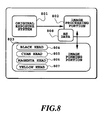
- Fig. 8 is a general block diagram showing a system actually performing head shading.
- the conventional head shading technology in the case where three systems of reading, image processing and printing are constructed in a single apparatus.
- an original exposure system 801 is a portion performing reading of an original, forms a portion of reading a result of printing necessary for performing head shading.
- An image processing portion 802 serves as a portion performing arithmetic operation and the like with respect to the image read by the original exposure system 801.
- the arithmetic operation performed in the image processing portion 802 includes color processing, binarizing process, head shaping and so on.
- An image forming portion 803 is a portion for printing an image read by the original exposure system 801 and processed by the image processing portion 802.
- the image forming portion 803 includes printing heads 804 to 807 for printing the images.
- 804 denotes a head for ejecting a black ink
- 805 denotes a head for ejecting a cyan ink
- 806 denotes a head for ejecting a magenta ink
- 807 denotes a head for ejecting a yellow ink.
- the printer constructed as set forth above, in order to check output characteristics of respective of the printing heads 804 to 807 in the image forming portion 803, printing of the predetermined test pattern is performed so that an image of the predetermined density is formed by respective of the printing heads 804 to 807. Then, the resultant print is read by the original exposure system 801.
- a read data read by the original exposure system 801 is used for forming a HS data 808 in the image processing portion 802.
- the HS data is data for correcting output density of ink per ink passage forming a plurality of nozzles in respective of the printing heads 804 to 807.
- the HS data 808 is used as a correction data for the image data input from the original exposure system 801 so as to make the density fleck not perceptible. As a result, an image avoided the density fleck is printed by the image forming portion 803.
- the original exposure system 801, the image processing portion 802 and the image forming portion 803 will never been separated individually. Therefore, a discrepancy such as that explained later, will never be caused between the characteristics of the printing heads 804 to 807 in the image forming portion 803 and the HS data 808.
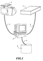
- a printer 1 in which a reader device 3, a computer terminal device 2 which can perform image processing and transmission, and a printer 1 are mutually independent, and connected through connection cable 5, as shown in Fig. 1, it is possible that the printer 1 is replaced with other printer.
- Another object of the present invention is to provide a printing method and a printing system which can avoid a problem to be caused by control of the printer with a correction data which has been obtained long ago exceeding a predetermined period, and whereby can improve a printing image quality.
- a printing method for selectively connecting a plurality of printers, each having a plurality of printing elements, to a control unit, and performing printing of an image on a printing medium by controlling the connected printer by the control unit, comprising the steps of:
- a printing system for selectively connecting a plurality of printers, each having a plurality of printing elements, to a control unit, and performing printing of an image on a printing medium by controlling the connected printer by the control unit, comprising the steps of:
- a printing method for printing an image on a printing medium with controlling a printer by a control unit comprising the steps of:
- a printing method for printing an image on a printing medium with controlling a printer by a control unit comprising the steps of:
- a printing system for printing an image on a printing medium with controlling a printer by a control unit comprising:
- a printing system for printing an image on a printing medium with controlling a printer by a control unit comprising:
- the present invention identifies printers selectively connected to the control unit to read out the dedicated correction data for control the selected printer, and controls the printer with using the dedicated correction data, therefor, the selected printer can be appropriately controlled with the dedicated correction data to permit printing of high quality image with no density fleck.
- the present invention identifies printers selectively connected to the control unit to read out the dedicated correction data for control the selected printer, and controls the printer with using the dedicated correction data and a setting data concerning the printing condition set per the printer, therefor, the selected printer can be appropriately controlled with the dedicated correction data to permit printing of high quality image with no density fleck.
- Fig. 1 is a general perspective view of a printing system, to which the present invention is applicable.
- a color bar code printer 1 as a printer using the system according to the present invention, employs a printing head having an ink passage forming a plurality of nozzles.
- the construction of the printing head is shown in Figs. 7A and 7B.
- As printing heads a head 704 for ejecting black ink, a head 703 for ejecting cyan ink, a head 702 for ejecting magenta ink and a head 701 for ejecting yellow ink are provided.
- Fig. 7B shows a perspective view of the head 701, as representative.
- the reference numeral 706 denote a plurality of ejection openings for ejecting the ink.
- the bar code printer 1 as the printer, a computer terminal device 2 which can perform image processing and transmission, an image scanner 3 as a reading device, and a storage device 4 storing foregoing HS data for correcting an output image are connected by connection cables 5.
- Fig. 3 is a flowchart for explaining operation from measuring output characteristics of the printing heads of the bar code printer 1 to generation HS data for performing image correction.
- predetermined density measuring pattern is printed by respective printing heads 701 to 704 (step S301).
- the density measuring pattern is a printing pattern, in which each printing heads 701 to 704 forms images of predetermined densities per unit area.
- a pattern in which density of printing images by respective printing heads 701 to 704 are 50%, was used.
- the result of printing of the density measuring pattern is read by the reading device 3 connected to the computer terminal device 2 (step S302) for detecting density fleck of the image printed by respective printing heads 701 to 704.
- the HS data is generated on the basis of the detecting data of density block (step S303).
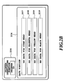
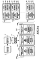
- Figs. 2A and 2B are explanatory illustrations showing a relationship between the printer and the storage content of the storage device 4.
- printer 1 various types of printers other than the bar code printer can be connected.
- printers 1, 2, ...., n those printers are identified as printers 1, 2, ...., n, and the printing heads for respective of cyan, magenta, yellow and black inks in each printer are identified as HC, HM, HY, HB.
- a HS data portion 204 and a printer identifying portion 206 are provided.
- the HS data portion 204 stores HS data 207, 208, 209 and 210 for the printing heads HC, HM, HY and HB of per each printers 1, 2 .... n, connected to the computer terminal device 2.
- the printer identifying portion 206 stores information consisted of symbol, figure or so forth for identifying the printers 1, 2, ...., n connected to the computer terminal device 2.
- printer IDs corresponding to printer IDs registered in respective printers 1, 2, ...., n are stored. By checking these printer IDs, the printers 1, 2 ...., n connected to the computer terminal device 2 is identified.
- the HS table is formed.
- Fig. 2B show one of the printer identifying portions 206 and the data portions 204 as representative.
- each of the printing heads HC, HM, HY and HB is provided with ink passages forming a plurality of nozzles. Therefore, it becomes necessary to know degree of printing density corresponding to each nozzle.
- read data obtained from the reading device 3, namely, the read data as a result of printing of the density measuring pattern performs analysis. With respect to the density of the predetermined density measuring pattern to be printed at the predetermined density, variation of the actual printing density is detected.
- the resolution of the read density data is converted into the resolution of the printer.
- the read density data for one line of the reading device 3 are corresponded to respective nozzles of each printing head.
- step S401 sampling process of the nozzle positions.
- the reading density data obtained from the reading device 3 becomes moderate at rising and falling edges of variation at the boundary between printing region and non-printing region. Therefore, it is difficult to assign the interval from the first nozzle to the final nozzle to the read density data.
- the first nozzle is statistically detected from the read density data, and then with reference to this, other nozzles are corresponded in the sequential order.
- step S402 an average value of the read density data corresponding to each nozzle is derived (step S402). Then it is used in the later stage for calculation of the correction value.
- a data shifting process in the next step is a process corresponding to variation of the read density data from the reading device 3 depending upon kinds of inks ejected from respective printing head. If where is a large difference between the average values of the read density data in each printing head, effect of correction which will be described later, should vary significantly per printing head. Thus, the average value of the read density data of each printing head is modified into the same value. For this purpose, the average value per each printing head is further averaged to derive an average value of the read density data common to respective head.
- a weighting process is the process for improving reliability of the value of the data, for which the sampling process is performed (step S401), namely for the read density data corresponded to each nozzle. Namely, by performing weighting for the peripheral data before and after the data in question, accurate process of the data value corresponding to each nozzle is enabled. Thus obtained read density data per each nozzle is compared with the average value of the read density data per printing head derived in preceding process to calculate a difference therebetween. Then, on the basis of the result of calculation, the HS data per each head is generated (step S406).
- the printer ID is added to the HS data so as to identify the corresponding printer (step S407) to establish a HS table (step S408).
- This HS table is stored in the storage device 4 connected to the computer terminal device 2. With making reference to or retrieving the HS table, head shading is performed.
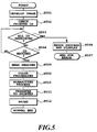
- the image data for which an output demand is issued from the computer terminal device 2 is converted into the image data in a form adapted for execution of the head shading (step S501).
- the printer ID of the printer currently connected to the computer terminal device 2 is checked (step S502).
- the printer ID is retrieved from all of HS tables registered in the storage device 4 (step S503).
- the printer ID is retrieved, it represents that the information of HS data and so on relating to the printer currently connected to the computer terminal device 2 is present.
- head shading is implemented using the retrieved HS data (step S505).
- retrieving process is repeated (steps S503 and S504).
- step S506 If the printer ID cannot be retrieved even after checking all of the HS tables stored in the storage device 4, judgment is made that the information, such as the HS data relating to the currently connected to the computer terminal device 2 is not present. Then, the fact is displayed by way of alarm or the like for error processing (step S506). A series of process is interrupted (step S507).
- step S505 Upon implementation of the head shading process (step S505), with respect to the image data divided per each printing head, arithmetic process for making the corresponding printing density of the image uniform. Namely, a difference between the average value of the common density data common to respective printing head in the HS data, and the density data of respective nozzle is derived. On the basis of the difference, head shading is performed. In the head shading, when the density data of the nozzle in question is lower than the average value, the printing density of the nozzle in question is increased. On the other hand, when the density data of the nozzle is higher than the average value, the printing density of the nozzle in question is reduced.
- step S505 After the head shading process (step S505), various color processes of output y correction, masking process, gray processing and so on is performed (step S509). Also, when the currently connected printer is a binary printer, after binarizing process, typically dither method, error diffusion method, is performed (step S510), and then the data is transferred to the printer (step S511) to perform printing (step S512).
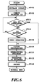
- Fig. 6 is flowchart for explaining another embodiment of head shading process employing the HS table similar to the first embodiment as set forth above.
- a point different from the first embodiment illustrated in Fig. 5 is that, when the printer ID is not retrieved at steps S503 and S504, the head shading process is skipped to advance the process to the color processing (step S509).
- the printers 1, 2, ..., n which can be connected as shown in Fig. 2, it is not specified to the color bar code printer, but can be various printer having the printing heads each formed with a plurality of nozzles.
- the present invention is widely applicable for printing systems having the computer terminal device 2 which can edit the printing data to be transferred to the printer.
- the printer, the computer terminal device 2 and the reading device are not specified.
- FIGs. 9A, 9B, 10 and 11 are illustration for explaining the third embodiment of the present invention.
- like elements to those in the former embodiment will be identified by the same reference numeral, and the detailed description therefor will be neglected.
- the printer identifying portion 206 of the storage device 4 shown in Fig. 9B the date and time, at which the HS data is obtained, they are stored as the time and date data 211.
- specific print setting value 212 is set with respect to printing medium.
- the print setting value 212 may be a printing arrange or a set value of margin of the printing medium.
- Fig. 9B shows one of the printer identifying portions 206 and the data portions 204 as representative.
- Fig. 10 is a flowchart for explaining HS data and HS table generating operation.
- a point different from the embodiment of Fig. 4 is that, the time and date, at which the HS date is obtained, they are registered in the identifying portion 206 (step S407A) as the time and date data 211. Accordingly, by adding the printing ID and the time and date data 211 to the HS data, the HS table can be established.
- Fig. 11 is a flowchart of explaining head shading process employing such HS table.
- the point different from the embodiment of Fig. 5A is that steps S504A, S504B, S504C, S504D and S504E are added. The following is the description for the additional steps.
- step S504A When the printer ID can be retrieved at step S504, reference is made to the time and date data 211 registered in the printer identifying portion 206 (step S504A). Then, if a period longer than a predetermined elapsed period has been elapsed after obtaining HS data corresponding to the currently retrieved printer ID, re-setting of the HS data is demanded (steps S504B, S504C). Then, process goes end (step S504D). Accordingly, a problem which can be caused when the head shading is performed using the HS data obtained long before, i.e. more than or equal to a predetermined period has been elapsed from obtaining the HS data in question, can be avoided. Namely, when the position of the density fleck is differentiated due to secular change of the printing head, correction using the old HS data should affect adversely.
- step S505 head shading is performed (step S505).
- certain type of printing heads requires to consider the printer setting value 212, such as printing range or margin set, for example. In such case, process will be performed with reference to the printer setting value 212.
- the printer 1 When the printer 1 is a so-called full line type printer, it has a printing head H extending in the width direction of the printing medium S. Then, printing is performed for printing the image on the printing medium by ejecting the ink from respective nozzles N of the printing head H with transporting the printing medium S in the longitudinal direction as indicated by arrow.
- the nozzles to be used are differentiated. Therefore, such set values are preliminarily set as the print setting value 212. By using such setting value 212, accurate head shading can be performed with assigning the corresponding HS data for the nozzles to be used.
- Fig. 12 is a flowchart showing another embodiment of the head shading processing operation using the same HS data as that in the third embodiment set forth above.
- the point different from the third embodiment of Fig. 11 is that, when the printer ID is not retrieved at steps S503 and S504, the head shading process is skipped to advance the process to the color processing (step S509).
- Fig. 13 is a flowchart for explaining a further embodiment of the head shading processing operation using the same HS data as that in the third embodiment set forth above.
- a point different from the foregoing third embodiment of Fig. 11 is that, when a period longer than or equal to the predetermined elapsed period has been elapsed after obtaining the HS data, the process is advanced from the step S504B to the color processing (step S509). Accordingly, in this case, the head shading process (step S505) is skipped to avoid problem which can be caused by implementation with the old HS data.
- Fig. 14 is a flowchart for explaining a still further embodiment of the head shading processing operation using the same HS data as that in the third embodiment set forth above.
- a point different from the former fifth embodiment of Fig. 13 is that, when the printer ID is not retrieved at steps S503 and S504, the head shading process is skipped and the process is advanced to the color processing (step S509).
- FIGs. 16A and 16B are explanatory illustration of the seventh embodiment of the present invention.
- like elements to those in the former embodiment will be identified by same reference numeral, and the detailed description therefor will be neglected.
- the time and date data 211 is stored in the printer identifying portion 206 of the storage device 4 of the first embodiment shown in Figs. 2A and 2B.
- Fig. 9B illustrates one of the printer identifying portions 206 and one of the data portion 204 as representative.
- the generating operation of the HS data and the HS table are the same as those in the third embodiment as explained with respect to Fig. 10.
- Fig. 17 is an explanatory illustration of the head shading processing operation using the HS table.
- the point different from the foregoing first embodiment of Fig. 5 is that, the steps S504A, S504B, S504C and S504D are added. The additional steps will be described hereinafter.
- step S504A When the printer ID can be retrieved at step S504, reference is made to the time and date data 211 registered in the printer identifying portion 206 (step S504A). Then, if a period longer than a predetermined elapsed period has been elapsed after obtaining HS data corresponding to the currently retrieved printer ID, re-setting of the HS data is demanded (steps S504B, S504C). Then, process goes end (step S504D). Accordingly, a problem which can be caused when the head shading is performed using the HS data obtained long before, i.e. more than or equal to a predetermined period has been elapsed from obtaining the HS data in question, can be avoided. Namely, when the position of the density fleck is differentiated due to secular change of the printing head, correction using the old HS data should affect adversely.
- head shading is performed (step S505).
- Fig. 18 is a flowchart for explaining a yet further embodiment of the head shading processing operation using the same HS table as that in the seventh embodiment set forth above.
- a point different from the seventh embodiment of Fig. 17 is that when the printer ID is not retrieved at steps S503 and S504, the head shading process is skipped and the process is directly advanced to the color processing (step S509).
- Fig. 19 is a flowchart for explaining a still further embodiment of the head shading processing operation using the same HS data as that in the seventh embodiment set forth above.
- a point different from the foregoing seventh embodiment of Fig. 17 is that, when a period longer than or equal to the predetermined elapsed period has been elapsed after obtaining the HS data, the process is advanced from the step S504B to the color processing (step S509). Accordingly, in this case, the head shading process (step S505) is skipped to avoid problem which can be caused by implementation with the old HS data.
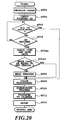
- Fig. 20 is a flowchart for explaining a still further embodiment of the head shading processing operation using the same HS data as that in the seventh embodiment set forth above.
- a point different from the former ninth embodiment of Fig. 19 is that, when the printer ID is not retrieved at steps S503 and S504, the head shading process is skipped and the process is advanced to the color processing (step S509).
- Figs. 21A, 21B, 22 and 23 are illustration for explaining the eleventh embodiment of the present invention.
- like elements to those in the former embodiment will be identified by the same reference numeral, and the detailed description therefor will be neglected.
- the HS data portion 204 and data attribute portion 215 are provided.
- the HS data portions 204 stores the HS data 207, 208, 209 and 210 of respective printing heads HC, HM, HY and HB of the printer 1 connected to the computer terminal device 2.
- the data attribute portion 215 stores the time and date data 211 indicative of time and date, at which the corresponding HS data is obtained.
- the printer 1 specific print setting value 212 for printing is set.
- the setting value 212 is the printing range or printing margin on the printing medium to be printed, for example.
- Fig. 22 is a flowchart for explaining operation for generating the HS data and HS table.
- a point different from the foregoing third embodiment illustrated in Fig. 10 is that the operation for adding the printer ID in Fig. 10 is neglected.
- a specific printer 1 is connected to the computer terminal device 2, it is not necessary to identify the printer connected to the computer terminal device 2 among a plurality of the printers.
- Fig. 23 is an explanatory illustration of the operation of head shading process using the HS table.
- a point different from the third embodiment in Fig. 11 is that, the steps S502, S503, S504, S506 and S507 are neglected.
- Fig. 24 is a flowchart for explaining a yet further embodiment of the head shading processing operation using the same HS table as that in the eleventh embodiment.
- a point different from the eleventh embodiment of Fig. 22 is that, when a period more than or equal to a predetermined elapsed period has been elapsed after obtaining the HS data, the process is advanced from step S504B to the color processing (step 509). Accordingly, in this case, the head shading process (step S505) is skipped to avoid problem which can be caused by implementation with the old HS data.
- the present invention achieves distinct effect when applied to a recording head or a recording apparatus which has means for generating thermal energy such as electrothermal transducers or laser light, and which causes changes in ink by the thermal energy so as to eject ink. This is because such a system can achieve a high density and high resolution recording.
- the on-demand type apparatus has electrothermal transducers, each disposed on a sheet or liquid passage that retains liquid (ink), and operates as follows: first, one or more drive signals are applied to the electrothermal transducers to cause thermal energy corresponding to recording information; second, the thermal energy induces sudden temperature rise that exceeds the nucleate boiling so as to cause the film boiling on heating portions of the recording head; and third, bubbles are grown in the liquid (ink) corresponding to the drive signals. By using the growth and collapse of the bubbles, the ink is expelled from at least one of the ink ejection orifices of the head to form one or more ink drops.
- the drive signal in the form of a pulse is preferable because the growth and collapse of the bubbles can be achieved instantaneously and suitably by this form of drive signal.
- a drive signal in the form of a pulse those described in U.S. patent Nos. 4,463,359 and 4,345,262 are preferable.
- the rate of temperature rise of the heating portions described in U.S. patent No. 4,313,124 be adopted to achieve better recording.
- U.S. patent Nos. 4,558,333 and 4,459,600 disclose the following structure of a recording head, which is incorporated to the present invention: this structure includes heating portions disposed on bent portions in addition to a combination of the ejection orifices, liquid passages and the electrothermal transducers disclosed in the above patents. Moreover, the present invention can be applied to structures disclosed in Japanese Patent Application Laying-open Nos. 123670/1984 and 138461/1984 in order to achieve similar effects.
- the former discloses a structure in which a slit common to all the electrothermal transducers is used as ejection orifices of the electrothermal transducers, and the latter discloses a structure in which openings for absorbing pressure waves caused by thermal energy are formed corresponding to the ejection orifices.
- the present invention can be also applied to a so-called full-line type recording head whose length equals the maximum length across a recording medium.
- a recording head may consists of a plurality of recording heads combined together, or one integrally arranged recording head.
- the present invention can be applied to various serial type recording heads: a recording head fixed to the main assembly of a recording apparatus; a conveniently replaceable chip type recording head which, when loaded on the main assembly of a recording apparatus, is electrically connected to the main assembly, and is supplied with ink therefrom; and a cartridge type recording head integrally including an ink reservoir.
- a recovery system or a preliminary auxiliary system for a recording head as a constituent of the recording apparatus because they serve to make the effect of the present invention more reliable.
- the recovery system are a capping means and a cleaning means for the recording head, and a pressure or suction means for the recording head.
- the preliminary auxiliary system are a preliminary heating means utilizing electrothermal transducers or a combination of other heater elements and the electrothermal transducers, and a means for carrying out preliminary ejection of ink independently of the ejection for recording. These systems are effective for reliable recording.
- the number and type of recording heads to be mounted on a recording apparatus can be also changed. For example, only one recording head corresponding to a single color ink, or a plurality of recording heads corresponding to a plurality of inks different in color or concentration can be used.
- the present invention can be effectively applied to an apparatus having at least one of the monochromatic, multi-color and full-color modes.
- the monochromatic mode performs recording by using only one major color such as black.
- the multi-color mode carries out recording by using different color inks, and the full-color mode performs recording by color mixing.
- inks that are liquid when the recording signal is applied can be used: for example, inks can be employed that solidify at a temperature lower than the room temperature and are softened or liquefied in the room temperature. This is because in the ink jet system, the ink is generally temperature adjusted in a range of 30°C - 70°C so that the viscosity of the ink is maintained at such a value that the ink can be ejected reliably.
- the present invention can be applied to such apparatus where the ink is liquefied just before the ejection by the thermal energy as follows so that the ink is expelled from the orifices in the liquid state, and then begins to solidify on hitting the recording medium, thereby preventing the ink evaporation: the ink is transformed from solid to liquid state by positively utilizing the thermal energy which would otherwise cause the temperature rise; or the ink, which is dry when left in air, is liquefied in response to the thermal energy of the recording signal.
- the ink may be retained in recesses or through holes formed in a porous sheet as liquid or solid substances so that the ink faces the electrothermal transducers as described in Japanese Patent Application Laying-open Nos. 56847/1979 or 71260/1985.
- the present invention is most effective when it uses the film boiling phenomenon to expel the ink.
- the ink jet recording apparatus of the present invention can be employed not only as an image output terminal of an information processing device such as a computer, but also as an output device of a copying machine including a reader, and as an output device of a facsimile apparatus having a transmission and receiving function.
Abstract
Description
- The present invention relates to a printing method and a printing system for printing an image on a printing medium under control by a control unit.
- In general, in a printer employing a printing head ejecting an ink from ink passages forming a plurality of nozzles, it is possible to cause density fleck in a printed image due to adverse effect of fine fluctuation of shapes of the ink passage forming the nozzles or to variation of ejection amount of the ink as printing material. One of the correction methods to make such density fleck not perceptible is called as head shading (HS).
- Fig. 8 is a general block diagram showing a system actually performing head shading. Hereinafter, at first, the conventional head shading technology in the case where three systems of reading, image processing and printing are constructed in a single apparatus.
- In Fig. 8, an
original exposure system 801 is a portion performing reading of an original, forms a portion of reading a result of printing necessary for performing head shading. Animage processing portion 802 serves as a portion performing arithmetic operation and the like with respect to the image read by theoriginal exposure system 801. The arithmetic operation performed in theimage processing portion 802 includes color processing, binarizing process, head shaping and so on. Animage forming portion 803 is a portion for printing an image read by theoriginal exposure system 801 and processed by theimage processing portion 802. Theimage forming portion 803 includesprinting heads 804 to 807 for printing the images. In the shown example, 804 denotes a head for ejecting a black ink, 805 denotes a head for ejecting a cyan ink, 806 denotes a head for ejecting a magenta ink and 807 denotes a head for ejecting a yellow ink. - In the printer constructed as set forth above, in order to check output characteristics of respective of the
printing heads 804 to 807 in theimage forming portion 803, printing of the predetermined test pattern is performed so that an image of the predetermined density is formed by respective of theprinting heads 804 to 807. Then, the resultant print is read by theoriginal exposure system 801. A read data read by theoriginal exposure system 801 is used for forming aHS data 808 in theimage processing portion 802. The HS data is data for correcting output density of ink per ink passage forming a plurality of nozzles in respective of theprinting heads 804 to 807. TheHS data 808 is used as a correction data for the image data input from theoriginal exposure system 801 so as to make the density fleck not perceptible. As a result, an image avoided the density fleck is printed by theimage forming portion 803. - In the printer constructed as set forth above, the
original exposure system 801, theimage processing portion 802 and theimage forming portion 803 will never been separated individually. Therefore, a discrepancy such as that explained later, will never be caused between the characteristics of theprinting heads 804 to 807 in theimage forming portion 803 and theHS data 808. - On the other hand, in a printing system, in which a
reader device 3, acomputer terminal device 2 which can perform image processing and transmission, and aprinter 1 are mutually independent, and connected throughconnection cable 5, as shown in Fig. 1, it is possible that theprinter 1 is replaced with other printer. - In the system construction as illustrated in Fig. 1, when the
printer 1 connected to thecomputer terminal device 2 is replaced, a discrepancy is inherently arisen between the characteristics of the printer and the HS data managed by thecomputer terminal device 2 to make it impossible to perform appropriate data correction. Therefore, in the prior art, head shading cannot be performed in the system shown in Fig. 1. - On the other hand, in the system construction set forth above, if condition of formation of the density fleck is varied due to secular change, it is possible that the HS data cannot be adapted to the secular change of the head to make it difficult to effect appropriate data correction. Particularly, where the printer is changed, appropriate data correction cannot be performed unless the HS data corresponding to the printer and the timing where the HS data is generated, are properly managed.
- It is an object of the present invention to provide a printing method and a printing system which can identify printers which are selectively connected to a control unit, and can control the selected printer with a dedicated data therefor to improve a printing image quality.
- Another object of the present invention is to provide a printing method and a printing system which can avoid a problem to be caused by control of the printer with a correction data which has been obtained long ago exceeding a predetermined period, and whereby can improve a printing image quality.
- In a first aspect of the present invention, there is provided a printing method for selectively connecting a plurality of printers, each having a plurality of printing elements, to a control unit, and performing printing of an image on a printing medium by controlling the connected printer by the control unit, comprising the steps of:
- storing correction data relative to control per each printer available for connection with the control unit, in a storage device;
- identifying the printer connected to the control unit to be controlled by the control unit, on the basis of an identification code corresponding to the printer;
- reading out the correction data corresponding to the printer identified as the object for control, from the storage device; and
- controlling the printer to be controlled using the read out correction data.
- In a second aspect of the present invention, there is provided a printing system for selectively connecting a plurality of printers, each having a plurality of printing elements, to a control unit, and performing printing of an image on a printing medium by controlling the connected printer by the control unit, comprising the steps of:
- a storage device storing correction data relative to control per each printer available for connection with the control unit;
- identifying means for identifying the printer connected to the control unit to be controlled by the control unit, on the basis of an identification code corresponding to the printer;
- retrieving means for retrieving the correction data corresponding to the printer identified as the object for control, from the storage device; and
- correction means for controlling the printer to be controlled using the read out correction data.
- In a third aspect of the present invention, there is provided a printing method for printing an image on a printing medium with controlling a printer by a control unit, comprising the steps of:
- storing a correction data relating to control of the printer and a storage time and date, on which the correction data is stored, in a storage device;
- reading out the correction data and the storage time and date upon controlling the printer, from the storage device;
- controlling the printer using the correction data when an elapsed time from the storage time and date is not more than or equal to a predetermined period; and
- interrupting control of the printer when an elapsed time from the storage time and date is more than or equal to a predetermined period.
- In a fourth aspect of the present invention, there is provided a printing method for printing an image on a printing medium with controlling a printer by a control unit, comprising the steps of:
- storing a correction data relating to control of the printer and storage time and date, on which the correction data is stored, in a storage device;
- reading out the correction and the storage time and date upon controlling the printer, from the storage device;
- controlling the printer using the correction data when an elapsed time from the storage time and date is not more than or equal to a predetermined period; and
- continuing control of the printer without using the correction data when an elapsed time from the storage time and data than or equal to a predetermined period.
- In a fifth aspect of the present invention, there is provided a printing system for printing an image on a printing medium with controlling a printer by a control unit, comprising:
- storage device for storing a correction data relating to control of the printer and a storage time and date, on which the correction data is stored;
- reading means for reading out the correction data and the storage time and date from the storage device upon controlling the printer;
- means for controlling the printer using the correction data when an elapsed time from the storage time and date is not more than or equal to a predetermined period;
- means for demanding resetting the correction data when an elapsed time from the storage time and date is more than equal to a predetermined period; and
- means for interrupting control for the printer when an elapsed time from the storage time and date is more than equal to a predetermined period.
- In a sixth aspect of the present invention, there is provided a printing system for printing an image on a printing medium with controlling a printer by a control unit, comprising:
- storage device for storing a correction data relating to control of the printer and a storage time and date, on which the correction data is stored;
- reading means for reading out the correction data and the storage time and date from the storage device upon controlling the printer;
- means for controlling the printer using the correction data when an elapsed time from the storage time and date is not more than or equal to a predetermined period; and
- means for continuing control of the printer without using the correction data when an elapsed time from the storage time and date is more than equal to a predetermined period.
- Since the present invention identifies printers selectively connected to the control unit to read out the dedicated correction data for control the selected printer, and controls the printer with using the dedicated correction data, therefor, the selected printer can be appropriately controlled with the dedicated correction data to permit printing of high quality image with no density fleck.
- Also, the present invention identifies printers selectively connected to the control unit to read out the dedicated correction data for control the selected printer, and controls the printer with using the dedicated correction data and a setting data concerning the printing condition set per the printer, therefor, the selected printer can be appropriately controlled with the dedicated correction data to permit printing of high quality image with no density fleck.
- On the other hand, by recording a time and date, at which the correction data is derived, it becomes possible to avoid a potential problem which may be caused in control using the correction data, about which a period longer than or equal to the predetermined period has past.
- The present invention will be understood more fully from the detailed description given hereinafter and from the accompanying drawings of the preferred embodiment of the present invention, which, however, should not be taken to be limitative to be present invention, but are for explanation and understanding only.
- In the drawings:
- Fig. 1 is a general perspective view of a printing system, to which the present invention is applicable;
- Fig. 2A is an illustration showing a general construction of the first embodiment of the present invention;
- Fig. 2B is an explanatory illustration of a HS table shown in Fig. 2A;
- Fig. 3 is a flowchart for explaining operation for generating a HS data in the first embodiment of the present invention;
- Fig. 4 is a flowchart for explaining a generating operation of a HS table in the first embodiment of the present invention;
- Fig. 5 is a flowchart for explaining a printing operation in the first embodiment of the present invention;
- Fig. 6 is a flowchart for explaining a printing operation in the second embodiment of the present invention;
- Fig. 7A is a side elevation of a printer, to which the present invention is applicable;
- Fig. 7B is an enlarged perspective view of the printing head is shown in Fig. 7A;
- Fig. 8 is an illustration showing general construction for explaining the conventional printing system;
- Fig. 9A is an illustration showing a general construction of the third embodiment of the present invention;
- Fig. 9B is an explanatory illustration of the HS table is shown in Fig. 9A;
- Fig. 10 is a flowchart for explaining operation for generating a HS table in the third embodiment of the present invention;
- Fig. 11 is a flowchart for explaining a printing operation in the third embodiment of the present invention;
- Fig. 12 is a flowchart for explaining a printing operation in the fourth embodiment of the present invention;
- Fig. 13 is a flowchart for explaining a printing operation in the fifth embodiment of the present invention;
- Fig. 14 is a flowchart for explaining a printing operation in the sixth embodiment of the present invention;
- Fig. 15 is an explanatory illustration for a printing set value shown in Fig. 9A;
- Fig. 16A is an illustration showing a general construction of the seventh embodiment of the present invention;
- Fig. 16B is an explanatory illustration of the HS table is shown in Fig. 16A;
- Fig. 17 is a flowchart for explaining a printing operation in the seventh embodiment of the present invention;
- Fig. 18 is a flowchart for explaining a printing operation in the eighth embodiment of the present invention;
- Fig. 19 is a flowchart for explaining a printing operation in the ninth embodiment of the present invention;
- Fig. 20 is a flowchart for explaining a printing operation in the tenth embodiment of the present invention;
- Fig. 21A is an illustration showing general construction of the eleventh embodiment of the present invention;
- Fig. 21B is an explanatory illustration of the HS table is shown in Fig. 21A;
- Fig. 22 is a flowchart for explaining a generating operation of a HS table in the eleventh embodiment of the present invention;
- Fig. 23 is a flowchart for explaining a printing operation in the eleventh embodiment of the present invention; and
- Fig. 24 is a flowchart for explaining a printing operation in the twelfth embodiment of the present invention.
- The present invention will be discussed hereinafter in detail in terms of the preferred embodiment of the present invention with reference to the accompanying drawings. In the following description, numerous specific details are set forth in order to provide a thorough understanding of the present invention. It will be obvious, however, to those skilled in the art that the present invention may be practiced without these specific details. In other instance, well-known structures are not shown in detail in order to avoid unnecessary obscure the present invention.
- Fig. 1 is a general perspective view of a printing system, to which the present invention is applicable. A color
bar code printer 1 as a printer using the system according to the present invention, employs a printing head having an ink passage forming a plurality of nozzles. The construction of the printing head is shown in Figs. 7A and 7B. As printing heads, ahead 704 for ejecting black ink, ahead 703 for ejecting cyan ink, ahead 702 for ejecting magenta ink and ahead 701 for ejecting yellow ink are provided. Fig. 7B shows a perspective view of thehead 701, as representative. In Fig. 7B, thereference numeral 706 denote a plurality of ejection openings for ejecting the ink. - In Fig. 1, the
bar code printer 1 as the printer, acomputer terminal device 2 which can perform image processing and transmission, animage scanner 3 as a reading device, and astorage device 4 storing foregoing HS data for correcting an output image are connected byconnection cables 5. - Fig. 3 is a flowchart for explaining operation from measuring output characteristics of the printing heads of the
bar code printer 1 to generation HS data for performing image correction. At first, for detecting density fleck of the printing image, predetermined density measuring pattern is printed by respective printing heads 701 to 704 (step S301). - The density measuring pattern is a printing pattern, in which each printing heads 701 to 704 forms images of predetermined densities per unit area. In this embodiment, a pattern, in which density of printing images by respective printing heads 701 to 704 are 50%, was used. Subsequently, the result of printing of the density measuring pattern is read by the
reading device 3 connected to the computer terminal device 2 (step S302) for detecting density fleck of the image printed by respective printing heads 701 to 704. Then, the HS data is generated on the basis of the detecting data of density block (step S303). - Figs. 2A and 2B are explanatory illustrations showing a relationship between the printer and the storage content of the
storage device 4. Here, as theprinter 1, various types of printers other than the bar code printer can be connected. In Fig. 2A, those printers are identified asprinters - In the
storage device 4, aHS data portion 204 and aprinter identifying portion 206 are provided. TheHS data portion 204stores HS data printers computer terminal device 2. Theprinter identifying portion 206 stores information consisted of symbol, figure or so forth for identifying theprinters computer terminal device 2. In theprinter identifying portion 206, printer IDs corresponding to printer IDs registered inrespective printers printers computer terminal device 2 is identified. By storage data in thedata portion 204 and theprinter identifying portion 206, the HS table is formed. On the other hand, Fig. 2B show one of theprinter identifying portions 206 and thedata portions 204 as representative. - As set forth above, each of the printing heads HC, HM, HY and HB is provided with ink passages forming a plurality of nozzles. Therefore, it becomes necessary to know degree of printing density corresponding to each nozzle. For this purpose, read data obtained from the
reading device 3, namely, the read data as a result of printing of the density measuring pattern, performs analysis. With respect to the density of the predetermined density measuring pattern to be printed at the predetermined density, variation of the actual printing density is detected. - Next, using flow chart of Fig. 4, generating operation of the HS data and HS table will be discussed.
- At first, in order to establish correspondence between read data obtained from the
reading device 3, namely the read density data as a result of printing of the density measuring pattern, and the nozzle of respective head, it becomes necessary to make the resolution of the read density data comparable with the resolution of the printer. Therefore, the resolution of the read density data is converted into the resolution of the printer. Here, the read density data for one line of thereading device 3 are corresponded to respective nozzles of each printing head. - In order to establish correspondence between the printing density corresponding to the nozzle of each printing head and the read density data of the
reading device 3, sampling process of the nozzle positions (step S401) is performed. Here, the reading density data obtained from thereading device 3 becomes moderate at rising and falling edges of variation at the boundary between printing region and non-printing region. Therefore, it is difficult to assign the interval from the first nozzle to the final nozzle to the read density data. Thus, paying attention for the portion of rising and falling of data variation, the first nozzle is statistically detected from the read density data, and then with reference to this, other nozzles are corresponded in the sequential order. - Next, per each printing head, an average value of the read density data corresponding to each nozzle is derived (step S402). Then it is used in the later stage for calculation of the correction value. A data shifting process in the next step (step S403) is a process corresponding to variation of the read density data from the
reading device 3 depending upon kinds of inks ejected from respective printing head. If where is a large difference between the average values of the read density data in each printing head, effect of correction which will be described later, should vary significantly per printing head. Thus, the average value of the read density data of each printing head is modified into the same value. For this purpose, the average value per each printing head is further averaged to derive an average value of the read density data common to respective head. - Then, a weighting process (step S404) is the process for improving reliability of the value of the data, for which the sampling process is performed (step S401), namely for the read density data corresponded to each nozzle. Namely, by performing weighting for the peripheral data before and after the data in question, accurate process of the data value corresponding to each nozzle is enabled. Thus obtained read density data per each nozzle is compared with the average value of the read density data per printing head derived in preceding process to calculate a difference therebetween. Then, on the basis of the result of calculation, the HS data per each head is generated (step S406).
- Also, the printer ID is added to the HS data so as to identify the corresponding printer (step S407) to establish a HS table (step S408). This HS table is stored in the
storage device 4 connected to thecomputer terminal device 2. With making reference to or retrieving the HS table, head shading is performed. - One example of operation of head shaping process employing the HS table will be explained with reference to Fig. 5.
- At first, the image data for which an output demand is issued from the
computer terminal device 2 is converted into the image data in a form adapted for execution of the head shading (step S501). Then, the printer ID of the printer currently connected to thecomputer terminal device 2 is checked (step S502). Then, the printer ID is retrieved from all of HS tables registered in the storage device 4 (step S503). Then, if the printer ID is retrieved, it represents that the information of HS data and so on relating to the printer currently connected to thecomputer terminal device 2 is present. Thus, head shading is implemented using the retrieved HS data (step S505). On the other hand, if the printer ID cannot be retrieved, retrieving process is repeated (steps S503 and S504). If the printer ID cannot be retrieved even after checking all of the HS tables stored in thestorage device 4, judgment is made that the information, such as the HS data relating to the currently connected to thecomputer terminal device 2 is not present. Then, the fact is displayed by way of alarm or the like for error processing (step S506). A series of process is interrupted (step S507). - Upon implementation of the head shading process (step S505), with respect to the image data divided per each printing head, arithmetic process for making the corresponding printing density of the image uniform. Namely, a difference between the average value of the common density data common to respective printing head in the HS data, and the density data of respective nozzle is derived. On the basis of the difference, head shading is performed. In the head shading, when the density data of the nozzle in question is lower than the average value, the printing density of the nozzle in question is increased. On the other hand, when the density data of the nozzle is higher than the average value, the printing density of the nozzle in question is reduced.
- After the head shading process (step S505), various color processes of output y correction, masking process, gray processing and so on is performed (step S509). Also, when the currently connected printer is a binary printer, after binarizing process, typically dither method, error diffusion method, is performed (step S510), and then the data is transferred to the printer (step S511) to perform printing (step S512).
- Fig. 6 is flowchart for explaining another embodiment of head shading process employing the HS table similar to the first embodiment as set forth above. In Fig. 6, a point different from the first embodiment illustrated in Fig. 5 is that, when the printer ID is not retrieved at steps S503 and S504, the head shading process is skipped to advance the process to the color processing (step S509).
- It should be noted that the
printers computer terminal device 2 which can edit the printing data to be transferred to the printer. The printer, thecomputer terminal device 2 and the reading device are not specified. - On the other hand, a method for determining the HS data, the color process (steps S509, S608) and the other steps, the binarizing process (steps S510, S609) in the process, the conventional processed can be used and thus no further explanation will be given. While the detailed discussion is neglected, concerning these processes, the method and procedure will not be limited.
- Figs. 9A, 9B, 10 and 11 are illustration for explaining the third embodiment of the present invention. In the following description, like elements to those in the former embodiment will be identified by the same reference numeral, and the detailed description therefor will be neglected.
- In case of the shown embodiment, for the
printer identifying portion 206 of thestorage device 4 shown in Fig. 9B, the date and time, at which the HS data is obtained, they are stored as the time anddate data 211. On the other hand, as shown in Fig. 9A, for theprinters print setting value 212 is set with respect to printing medium. Theprint setting value 212 may be a printing arrange or a set value of margin of the printing medium. Fig. 9B shows one of theprinter identifying portions 206 and thedata portions 204 as representative. - Fig. 10 is a flowchart for explaining HS data and HS table generating operation. In Fig. 10, a point different from the embodiment of Fig. 4 is that, the time and date, at which the HS date is obtained, they are registered in the identifying portion 206 (step S407A) as the time and
date data 211. Accordingly, by adding the printing ID and the time anddate data 211 to the HS data, the HS table can be established. Fig. 11 is a flowchart of explaining head shading process employing such HS table. In this Fig. 11, the point different from the embodiment of Fig. 5A is that steps S504A, S504B, S504C, S504D and S504E are added. The following is the description for the additional steps. - When the printer ID can be retrieved at step S504, reference is made to the time and
date data 211 registered in the printer identifying portion 206 (step S504A). Then, if a period longer than a predetermined elapsed period has been elapsed after obtaining HS data corresponding to the currently retrieved printer ID, re-setting of the HS data is demanded (steps S504B, S504C). Then, process goes end (step S504D). Accordingly, a problem which can be caused when the head shading is performed using the HS data obtained long before, i.e. more than or equal to a predetermined period has been elapsed from obtaining the HS data in question, can be avoided. Namely, when the position of the density fleck is differentiated due to secular change of the printing head, correction using the old HS data should affect adversely. - If the predetermined period is not yet elapsed from obtaining the HS data, with reference to the
printer setting value 212 registered in the currently connected printer (step S504E), head shading is performed (step S505). When the head shading is performed, certain type of printing heads requires to consider theprinter setting value 212, such as printing range or margin set, for example. In such case, process will be performed with reference to theprinter setting value 212. - Here, the
print setting value 212 will be described. - When the
printer 1 is a so-called full line type printer, it has a printing head H extending in the width direction of the printing medium S. Then, printing is performed for printing the image on the printing medium by ejecting the ink from respective nozzles N of the printing head H with transporting the printing medium S in the longitudinal direction as indicated by arrow. In case of such printer, depending on the set values of the printing ranges L1-A, L2-A for the printing medium S and set values of the margin L1-B, L2-B, the nozzles to be used are differentiated. Therefore, such set values are preliminarily set as theprint setting value 212. By usingsuch setting value 212, accurate head shading can be performed with assigning the corresponding HS data for the nozzles to be used. - Fig. 12 is a flowchart showing another embodiment of the head shading processing operation using the same HS data as that in the third embodiment set forth above. In Fig. 12, the point different from the third embodiment of Fig. 11 is that, when the printer ID is not retrieved at steps S503 and S504, the head shading process is skipped to advance the process to the color processing (step S509).
- Fig. 13 is a flowchart for explaining a further embodiment of the head shading processing operation using the same HS data as that in the third embodiment set forth above. In Fig. 13, a point different from the foregoing third embodiment of Fig. 11 is that, when a period longer than or equal to the predetermined elapsed period has been elapsed after obtaining the HS data, the process is advanced from the step S504B to the color processing (step S509). Accordingly, in this case, the head shading process (step S505) is skipped to avoid problem which can be caused by implementation with the old HS data.
- Fig. 14 is a flowchart for explaining a still further embodiment of the head shading processing operation using the same HS data as that in the third embodiment set forth above. In Fig. 14, a point different from the former fifth embodiment of Fig. 13 is that, when the printer ID is not retrieved at steps S503 and S504, the head shading process is skipped and the process is advanced to the color processing (step S509).
- Figs. 16A and 16B are explanatory illustration of the seventh embodiment of the present invention. In the following description, like elements to those in the former embodiment will be identified by same reference numeral, and the detailed description therefor will be neglected.
- In the shown embodiment, as shown in Fig. 9B, the time and
date data 211 is stored in theprinter identifying portion 206 of thestorage device 4 of the first embodiment shown in Figs. 2A and 2B. Fig. 9B illustrates one of theprinter identifying portions 206 and one of thedata portion 204 as representative. The generating operation of the HS data and the HS table are the same as those in the third embodiment as explained with respect to Fig. 10. - Fig. 17 is an explanatory illustration of the head shading processing operation using the HS table. In Fig. 17, the point different from the foregoing first embodiment of Fig. 5 is that, the steps S504A, S504B, S504C and S504D are added. The additional steps will be described hereinafter.
- When the printer ID can be retrieved at step S504, reference is made to the time and
date data 211 registered in the printer identifying portion 206 (step S504A). Then, if a period longer than a predetermined elapsed period has been elapsed after obtaining HS data corresponding to the currently retrieved printer ID, re-setting of the HS data is demanded (steps S504B, S504C). Then, process goes end (step S504D). Accordingly, a problem which can be caused when the head shading is performed using the HS data obtained long before, i.e. more than or equal to a predetermined period has been elapsed from obtaining the HS data in question, can be avoided. Namely, when the position of the density fleck is differentiated due to secular change of the printing head, correction using the old HS data should affect adversely. - If the predetermined period is not yet elapsed from obtaining the HS data, head shading is performed (step S505).
- Fig. 18 is a flowchart for explaining a yet further embodiment of the head shading processing operation using the same HS table as that in the seventh embodiment set forth above. In Fig. 18, a point different from the seventh embodiment of Fig. 17 is that when the printer ID is not retrieved at steps S503 and S504, the head shading process is skipped and the process is directly advanced to the color processing (step S509).
- Fig. 19 is a flowchart for explaining a still further embodiment of the head shading processing operation using the same HS data as that in the seventh embodiment set forth above. In Fig. 19, a point different from the foregoing seventh embodiment of Fig. 17 is that, when a period longer than or equal to the predetermined elapsed period has been elapsed after obtaining the HS data, the process is advanced from the step S504B to the color processing (step S509). Accordingly, in this case, the head shading process (step S505) is skipped to avoid problem which can be caused by implementation with the old HS data.
- Fig. 20 is a flowchart for explaining a still further embodiment of the head shading processing operation using the same HS data as that in the seventh embodiment set forth above. In Fig. 20, a point different from the former ninth embodiment of Fig. 19 is that, when the printer ID is not retrieved at steps S503 and S504, the head shading process is skipped and the process is advanced to the color processing (step S509).
- Figs. 21A, 21B, 22 and 23 are illustration for explaining the eleventh embodiment of the present invention. In the following description, like elements to those in the former embodiment will be identified by the same reference numeral, and the detailed description therefor will be neglected.
- In the
storage device 4, theHS data portion 204 and data attributeportion 215 are provided. TheHS data portions 204 stores theHS data printer 1 connected to thecomputer terminal device 2. The data attributeportion 215 stores the time anddate data 211 indicative of time and date, at which the corresponding HS data is obtained. By the stored data in theHS data portion 204 and the data attributeportion 215, the HS table is established. In theprinter 1, specificprint setting value 212 for printing is set. The settingvalue 212 is the printing range or printing margin on the printing medium to be printed, for example. - Fig. 22 is a flowchart for explaining operation for generating the HS data and HS table. In Fig. 22, a point different from the foregoing third embodiment illustrated in Fig. 10 is that the operation for adding the printer ID in Fig. 10 is neglected. In the shown embodiment, a
specific printer 1 is connected to thecomputer terminal device 2, it is not necessary to identify the printer connected to thecomputer terminal device 2 among a plurality of the printers. - Fig. 23 is an explanatory illustration of the operation of head shading process using the HS table. In Fig. 23, a point different from the third embodiment in Fig. 11 is that, the steps S502, S503, S504, S506 and S507 are neglected.
- Fig. 24 is a flowchart for explaining a yet further embodiment of the head shading processing operation using the same HS table as that in the eleventh embodiment. In Fig. 24, a point different from the eleventh embodiment of Fig. 22 is that, when a period more than or equal to a predetermined elapsed period has been elapsed after obtaining the HS data, the process is advanced from step S504B to the color processing (step 509). Accordingly, in this case, the head shading process (step S505) is skipped to avoid problem which can be caused by implementation with the old HS data.
- The present invention achieves distinct effect when applied to a recording head or a recording apparatus which has means for generating thermal energy such as electrothermal transducers or laser light, and which causes changes in ink by the thermal energy so as to eject ink. This is because such a system can achieve a high density and high resolution recording.
- A typical structure and operational principle thereof is disclosed in U.S. patent Nos. 4,723,129 and 4,740,796, and it is preferable to use this basic principle to implement such a system. Although this system can be applied either to on-demand type or continuous type ink jet recording systems, it is particularly suitable for the on-demand type apparatus. This is because the on-demand type apparatus has electrothermal transducers, each disposed on a sheet or liquid passage that retains liquid (ink), and operates as follows: first, one or more drive signals are applied to the electrothermal transducers to cause thermal energy corresponding to recording information; second, the thermal energy induces sudden temperature rise that exceeds the nucleate boiling so as to cause the film boiling on heating portions of the recording head; and third, bubbles are grown in the liquid (ink) corresponding to the drive signals. By using the growth and collapse of the bubbles, the ink is expelled from at least one of the ink ejection orifices of the head to form one or more ink drops. The drive signal in the form of a pulse is preferable because the growth and collapse of the bubbles can be achieved instantaneously and suitably by this form of drive signal. As a drive signal in the form of a pulse, those described in U.S. patent Nos. 4,463,359 and 4,345,262 are preferable. In addition, it is preferable that the rate of temperature rise of the heating portions described in U.S. patent No. 4,313,124 be adopted to achieve better recording.
- U.S. patent Nos. 4,558,333 and 4,459,600 disclose the following structure of a recording head, which is incorporated to the present invention: this structure includes heating portions disposed on bent portions in addition to a combination of the ejection orifices, liquid passages and the electrothermal transducers disclosed in the above patents. Moreover, the present invention can be applied to structures disclosed in Japanese Patent Application Laying-open Nos. 123670/1984 and 138461/1984 in order to achieve similar effects. The former discloses a structure in which a slit common to all the electrothermal transducers is used as ejection orifices of the electrothermal transducers, and the latter discloses a structure in which openings for absorbing pressure waves caused by thermal energy are formed corresponding to the ejection orifices. Thus, irrespective of the type of the recording head, the present invention can achieve recording positively and effectively.
- The present invention can be also applied to a so-called full-line type recording head whose length equals the maximum length across a recording medium. Such a recording head may consists of a plurality of recording heads combined together, or one integrally arranged recording head.
- In addition, the present invention can be applied to various serial type recording heads: a recording head fixed to the main assembly of a recording apparatus; a conveniently replaceable chip type recording head which, when loaded on the main assembly of a recording apparatus, is electrically connected to the main assembly, and is supplied with ink therefrom; and a cartridge type recording head integrally including an ink reservoir.
- It is further preferable to add a recovery system, or a preliminary auxiliary system for a recording head as a constituent of the recording apparatus because they serve to make the effect of the present invention more reliable. As examples of the recovery system, are a capping means and a cleaning means for the recording head, and a pressure or suction means for the recording head. As examples of the preliminary auxiliary system, are a preliminary heating means utilizing electrothermal transducers or a combination of other heater elements and the electrothermal transducers, and a means for carrying out preliminary ejection of ink independently of the ejection for recording. These systems are effective for reliable recording.
- The number and type of recording heads to be mounted on a recording apparatus can be also changed. For example, only one recording head corresponding to a single color ink, or a plurality of recording heads corresponding to a plurality of inks different in color or concentration can be used. In other words, the present invention can be effectively applied to an apparatus having at least one of the monochromatic, multi-color and full-color modes. Here, the monochromatic mode performs recording by using only one major color such as black. The multi-color mode carries out recording by using different color inks, and the full-color mode performs recording by color mixing.
- Furthermore, although the above-described embodiments use liquid ink, inks that are liquid when the recording signal is applied can be used: for example, inks can be employed that solidify at a temperature lower than the room temperature and are softened or liquefied in the room temperature. This is because in the ink jet system, the ink is generally temperature adjusted in a range of 30°C - 70°C so that the viscosity of the ink is maintained at such a value that the ink can be ejected reliably.
- In addition, the present invention can be applied to such apparatus where the ink is liquefied just before the ejection by the thermal energy as follows so that the ink is expelled from the orifices in the liquid state, and then begins to solidify on hitting the recording medium, thereby preventing the ink evaporation: the ink is transformed from solid to liquid state by positively utilizing the thermal energy which would otherwise cause the temperature rise; or the ink, which is dry when left in air, is liquefied in response to the thermal energy of the recording signal. In such cases, the ink may be retained in recesses or through holes formed in a porous sheet as liquid or solid substances so that the ink faces the electrothermal transducers as described in Japanese Patent Application Laying-open Nos. 56847/1979 or 71260/1985. The present invention is most effective when it uses the film boiling phenomenon to expel the ink.
- Furthermore, the ink jet recording apparatus of the present invention can be employed not only as an image output terminal of an information processing device such as a computer, but also as an output device of a copying machine including a reader, and as an output device of a facsimile apparatus having a transmission and receiving function.
- The present invention has been described in detail with respect to various embodiments, and it will now be apparent from the foregoing to those skilled in the art that changes and modifications may be made without departing from the invention in its broader aspects, and it is the intention, therefore, in the appended claims to cover all such changes and modifications as fall within the true spirit of the invention.
Claims (53)
- A printing method for selectively connecting a plurality of printers, each having a plurality of printing elements, to a control unit, and performing printing of an image on a printing medium by controlling the connected printer by said control unit, characterized by comprising the steps of:storing correction data relative to control per each printer available for connection with said control unit, in a storage device;identifying the printer connected to said control unit to be controlled by said control unit, on the basis of an identification code corresponding to said printer;reading out the correction data corresponding to the printer identified as the object for control, from said storage device; andcontrolling the printer to be controlled using the read out correction data.
- A printing method as claimed in claim 1, characterized in that said correction data is a correction data relating to control per each of said printing elements of said printer.
- A printing method as claimed in claim 1, characterized in that said correction data is a correction data relating to a printing density per each of said printing elements of said printer.
- A printing method as claimed in claim 1, characterized in that said correction data is a correction data relating to a printing density per each of said printing elements of said printer, and
said correction data is derived on the basis of a reading data of a result of printing when a predetermined density pattern of image is printed on said printing medium by said printer. - A printing method as claimed in claim 1, characterized in that said correction data is stored in said storage device with correspondence to said identification code,
by retrieving said identification code, said correction data corresponding to the retrieved identification code is read out from said storage device. - A printing method as claimed in claim 5, characterized in that when said identification code is not retrieved from said storage device, the fact is displayed and control for the printer connected to said control unit as the object for control is interrupted.
- A printing method as claimed in claim 5, characterized in that when said identification code is not retrieved from said storage device, control for the printer connected to said control unit as the object for control is maintained without using said correction data.
- A printing method as claimed in claim 1, characterized in that a plurality of printing elements of said printer forms an ink-jet head ejecting an ink.
- A printing method as claimed in claim 8, characterized in that said ink-jet head has an electrothermal transducer for generating film boiling in said ink for ejecting said ink.
- A printing system for selectively connecting a plurality of printers, each having a plurality of printing elements, to a control unit, and performing printing of an image on a printing medium by controlling the connected printer by said control unit, characterized by comprising the steps of:a storage device storing correction data relative to control per each printer available for connection with said control unit;identifying means for identifying the printer connected to said control unit to be controlled by said control unit, on the basis of an identification code corresponding to said printer;retrieving means for retrieving the correction data corresponding to the printer identified as the object for control, from said storage device; andcorrection means for controlling the printer to be controlled using the read out correction data.
- A printing system as claimed in claim 10, characterized in that said storage device stores said correction data as a correction data relating to control per each of said printing elements of said printer.
- A printing system as claimed in claim 10, characterized in that said storage device stores said correction data as a correction data relating to a printing density per each of said printing elements of said printer.
- A printing system as claimed in claim 10, characterized in that said storage device stores said correction data as a correction data relating to a printing density per each of said printing elements of said printer, andsaid printing system includesreading device for reading a result of printing when said printer performing printing of a predetermined density pattern on said printing medium; andmeans for deriving said correction data on the basis of the read data of said reading device.
- A printing system as claimed in claim 10, characterized in that said storage device stores said correction data with correspondence to said identification code,
said retrieving means retrieving said identification code for reading out said correction data corresponding to the retrieved identification code from said storage device. - A printing system as claimed in claim 14, which further comprises a display means for announcement when said retrieving means fails to retrieve said identification code from said storage device, and
means for interrupting control for the printer connected to said control unit as the object for control, when said retrieving means foils to retrieve said identification code from said storage device. - A printing system as claimed in claim 14, which further comprises means for continues control for the printer connected to said control unit as the object for control without using said correction data, when said retrieving means fails to retrieve said identification code from said storage device,
- A printing system as claimed in claim 10, characterized in that a plurality of printing elements of said printer forms an ink-jet head ejecting an ink.
- A printing system as claimed in claim 17, characterized in that said ink-jet head has an electrothermal transducer for generating film boiling in said ink for ejecting said ink.
- A printing method as claimed in claim 1, which comprises the steps of:setting a setting data relating to setting of a printing condition of said printer, provided in said printer;identifying the printer connected to said control unit to be controlled by said control unit, on the basis of an identification code corresponding to said printer;reading out the correction data corresponding to the printer identified as the object for control, from said storage device; andcontrolling the printer to be controlled using the read out correction data and said setting data of said printer as object for control.
- A printing method as claimed in claim 19, characterized in that said correction data is a correction data relating to control per each of said printing elements of said printer.
- A printing method as claimed in claim 19, characterized in that said correction data is a correction data relating to a printing density per each of said printing elements of said printer.
- A printing method as claimed in claim 19, characterized in that said correction data is a correction data relating to a printing density per each of said printing elements of said printer, and
said correction data is derived on the basis of a reading data of a result of printing when a predetermined density pattern of image is printed on said printing medium by said printer. - A printing method as claimed in claim 19, characterized in that printing is performed using a plurality of said printing elements arranged along the width direction of said printing medium with transporting said printing medium in the longitudinal direction upon printing an image on said printing medium;said correction data is a correction data for a printing density per each of said printing elements;said setting data is a set value of a printing region with respect to said printing medium; andsaid correction data is assigned for respective said printing elements located within said printing region on the basis of said setting data.
- A printing method as claimed in claim 19, characterized in that printing is performed using a plurality of said printing elements arranged along the width direction of said printing medium with transporting said printing medium in the longitudinal direction upon printing an image on said printing medium;said correction data is a correction data for a printing density per each of said printing elements;said setting data is a set value of a printing margin with respect to said printing medium; andsaid correction data is assigned for respective said printing elements located out of said printing margin on the basis of said setting data.
- A printing method as claimed in claim 19, characterized in that also storing a time and date on which said correction data is stored, in said storage device,
upon controlling the printer as the object for control using said correction data and said setting data, when a period longer than or equal to a predetermined period has elapsed from said stored time and date, the fact is displayed and control of the printer as the object for control is interrupted. - A printing method as claimed in claim 19, characterized in that also storing a time and date on which said correction data is stored, in said storage device,
upon controlling the printer as the object for control using said correction data and said setting data, when a period longer than or equal to a predetermined period has elapsed from said stored time and date, control of the printer as the object for control is maintained without using said correction data and said setting data. - A printing system as claimed in claim 10, which further comprises:setting means for setting a setting data relating to setting of a printing condition of said printer, provided said printer; andsaid correction means corrects content of control for the printer to be controlled using said read out correction data and said setting data of the printer as object for control.
- A printing system as claimed in claim 27, characterized in that said storage device stores said correction data as a correction data relating to control per each of said printing elements of said printer.
- A printing system as claimed in claim 27, characterized in that said storage device stores said correction data as a correction data relating to a printing density per each of said printing elements of said printer.
- A printing system as claimed in claim 28, which further comprises:transporting means for transporting said printing medium in the longitudinal direction;a plurality of printing elements are arranged in the width direction of said printing medium;said storage device stores said correction data as a correction data relating to a printing density per each of said printing element of said printer, andsaid setting means sets a set value of a printing region with respect to said printing medium as said setting data; andsaid correction means assigns said correction data for corresponding said printing elements located within said printing region on the basis of said setting data.
- A printing system as claimed in claim 28, which further comprises:transporting means for transporting said printing medium in the longitudinal direction;a plurality of printing elements are arranged in the width direction of said printing medium;said storage device stores said correction data as a correction data relating to a printing density per each of said printing element of said printer, andsaid setting means sets a set value of a printing margin with respect to said printing medium as said setting data; andsaid correction means assigns said correction data for corresponding said printing elements located out of said printing margin on said basis of the setting data.
- A printing system as claimed in claim 27, characterized in that said storage device also stores a time and date on which said correction data is stored,said printing system includesdisplay means for displaying a fact upon controlling the printer as the object for control using said correction data and said setting data, when a period longer than or equal to a predetermined period has elapsed from said stored time and date,means for interrupting control for the printer as object for control, upon controlling the printer as the object for control using said correction data and said setting data, and when a period longer than or equal to a predetermined period has elapsed from said stored time and date.
- A printing system as claimed in claim 27, characterized in that said storage device also stores a time and date on which said correction data is stored,
said printing system includes means for continues control the printer as the object for control without using said correction data and said setting data, upon controlling the printer as the object for control using said correction data and said setting data, when a period longer than or equal to a predetermined period has elapsed from said stored time and date. - A printing method as claimed in claim 1, which comprises the steps of:setting said correction data relating to control per each printer available for connection with said control unit and a time and date on which said correction data is stored, in said storage device,identifying the printer connected to said control unit to be controlled by said control unit, on the basis of an identification code corresponding to said printer;reading out the correction data corresponding to the printer identified as the object for control, from said storage device; andupon controlling the printer as the object for control using said correction data, when a period longer than or equal to a predetermined period has elapsed from said stored time and date, the fact is displayed and control of the printer as the object for control is interrupted.
- A printing method as claimed in claim 1, which comprises the steps of:setting said correction data relating to control per each printer available for connection with said control unit and a time and date on which said correction data is stored, in said storage device,identifying the printer connected to said control unit to be controlled by said control unit, on the basis of an identification code corresponding to said printer;reading out the correction data corresponding to the printer identified as the object for control, from said storage device; andupon controlling the printer as the object for control using said correction data, when a period longer than or equal to a predetermined period has elapsed from said stored time and date, control of the printer as the object for control is maintained without using said correction data.
- A printing system as claimed in claim 10, characterized in that said storage device stores said correction data relating to control per each printer connected to said control unit and a storage time and date, on which said correction data is stored, andsaid printing system further comprises:display means for displaying a fort upon controlling the printer as the object for control using said correction data, when a period longer than or equal to a predetermined period has elapsed from said stored time and date,means for interrupting control for the printer as object for control, upon controlling the printer as the object for control using said correction data and said setting data, and when a period longer than or equal to a predetermined period has elapsed from said stored time and date.
- A printing system as claimed in claim 10, characterized in that said storage device stores said correction data relating to control per each printer connected to said control unit and a storage time and date, on which said correction data is stored,
said printing system includes means for continues control the printer as the object for control without using said correction data, upon controlling the printer as the object for control using said correction data, when a period longer than or equal to a predetermined period has elapsed from said stored time and date. - A printing method for printing an image on a printing medium with controlling a printer by a control unit, characterized by comprising the steps of:storing a correction data relating to control of said printer and a storage time and date, on which said correction data is stored, in a storage device;reading out said correction data and said storage time and date upon controlling said printer, from said storage device;controlling said printer using said correction data when an elapsed time from said storage time and date is not more than or equal to a predetermined period; andinterrupting control of said printer when an elapsed time from said storage time and date is more than or equal to a predetermined period.
- A printing method as claimed in claim 38, characterized in that said printer is set a setting data relating to setting of a printing condition of said printer;
said printer is controlled using said setting data when said printer is controlled using said correction data. - A printing method as claimed in claim 39, characterized in that printing is performed using a plurality of printing elements arranged in the width direction of said printing medium with transporting said printing medium in a longitudinal direction upon printing an image on said printing medium,said correction data is a correction data for a printing density per each said printing element;said setting data is a set value of a printing region with respect to said printing medium; andsaid correction data is assigned for respective said printing elements located within said printing region on the basis of said setting data.
- A printing method as claimed in claim 39, characterized in that printing is performed using a plurality of printing elements arranged in the width direction of said printing medium with transporting said printing medium in a longitudinal direction upon printing on image on said printing medium,said correction data is a correction data for a printing density per each said printing element;said setting data is a set value of a printing margin with respect to said printing medium; andsaid correction data is assigned for respective said printing elements located out of said printing margin on the basis of said setting data.
- A printing method for printing an image on a printing medium with controlling a printer by a control unit, characterized by comprising the steps of:storing a correction data relating to control of said printer and storage time and date, on which said correction data is stored, in a storage device;reading out said correction and said storage time and date upon controlling said printer, from said storage device;controlling said printer using said correction data when an elapsed time from said storage time and date is not more than or equal to a predetermined period; andcontinuing control of said printer without using said correction data when an elapsed time from said storage time and data than or equal to a predetermined period.
- A printing method as claimed in claim 42, characterized in that said printer is set a setting data relating to setting of a printing condition of said printer;
said printer is controlled using said setting data when said printer is controlled using said correction data. - A printing method as claimed in claim 43, characterized in that printing is performed using a plurality of said printing elements arranged in width direction of said printing medium with transporting said printing medium in a longitudinal direction upon printing an image on said printing medium,said correction data is a correction data for a printing density per said each printing element;said setting data is a set value of a printing region with respect to the printing medium; andsaid correction data is assigned for respective said printing elements located within said printing region on the basis of said setting data.
- A printing method as claimed in claim 43, characterized in that printing is performed using a plurality of said printing elements arranged in width direction of said printing medium with transporting said printing medium in a longitudinal direction upon printing an image on said printing medium,said correction data is a correction data for a printing density per each said printing element;said setting data is a set valued of a printing margin with respect to the printing medium; andsaid correction data is assigned for respective said printing elements located out of said printing margin on the basis of said setting data.
- A printing system for printing an image on a printing medium with controlling a printer by a control unit, characterized by comprising:storage device for storing a correction data relating to control of said printer and a storage time and date, on which said correction data is stored;reading means for reading out said correction data and said storage time and date from said storage device upon controlling said printer;means for controlling said printer using said correction data when an elapsed time from said storage time and date is not more than or equal to a predetermined period;means for demanding resetting said correction data when an elapsed time from said storage time and date is more than equal to a predetermined period; andmeans for interrupting control for said printer when an elapsed time from said storage time and date is more than equal to a predetermined period.
- A printing system as claimed in claim 46, which further comprises:setting means for setting a setting data relating to setting of a printing condition of said printer provided in said printer; andmeans for controlling said printer using said setting data when said printer is controlled using said correction data.
- A printing system as claimed in claim 47, which further comprises:transporting means for transporting said printing medium in the longitudinal direction;a plurality of printing elements arranged in width direction of said printing medium;said storage device stores said correction data as a printing density per each said printing element;said setting means sets said setting data as a value of a printing region with respect to said printing medium; andsaid correction means assigns said correction data to corresponding said printing elements located within said printing region on the basis of said setting data.
- A printing system as claimed in claim 47, which further comprises:transporting means for transporting said printing medium in the longitudinal direction;a plurality of printing elements arranged in width direction of said printing medium;said storage device storage said correction data as a printing density per each said printing element;said setting means sets said setting data as a value of a printing margin with respect to said printing medium; andsaid correction means assigns said correction data to corresponding said printing elements located out of said printing margin on the basis of said setting data.
- A printing system for printing an image on a printing medium with controlling a printer by a control unit, characterized by comprising:storage device for storing a correction data relating to control of said printer and a storage time and date, on which said correction data is stored;reading means for reading out said correction data and said storage time and date from said storage device upon controlling said printer;means for controlling said printer using said correction data when an elapsed time from said storage time and date is not more than or equal to a predetermined period; andmeans for continuing control of said printer without using said correction data when an elapsed time from said storage time and date is more than equal to a predetermined period.
- A printing system as claimed in claim 50, which further comprises:setting means for setting a setting data relating to the setting of the printing condition of said printer, provided in said printer, andmeans for controlling said printer using said setting data when said printer is controlled using said correction data.
- A printing system as claimed in claim 51, which further comprises:transporting means for transporting said printing medium in the longitudinal direction;a plurality of printing elements arranged in width direction of said printing medium;said storage device stores said correction data as a printing density per each said printing element;said setting means sets said setting data as a value of said printing region with respect to said printing medium; andsaid correction means assigns said correction data to corresponding said printing elements located within said printing region on the basis of said setting data.
- A printing system as claimed in claim 51, which further comprises:transporting means for transporting said printing medium in the longitudinal direction;a plurality of printing elements arranged in width direction of said printing medium;said storage device stores said correction data as a printing density per each printing element;said setting means sets said setting data as a value of a printing margin with respect to said printing medium; andsaid correction means assigning said correction data to corresponding said printing elements located out of said printing margin on the basis of said setting data.
Applications Claiming Priority (12)
| Application Number | Priority Date | Filing Date | Title |
|---|---|---|---|
| JP8156803A JPH10767A (en) | 1996-06-18 | 1996-06-18 | Printing method and printing apparatus |
| JP15682096 | 1996-06-18 | ||
| JP15682096A JP3441600B2 (en) | 1996-06-18 | 1996-06-18 | Printing method and printing system |
| JP156822/96 | 1996-06-18 | ||
| JP156813/96 | 1996-06-18 | ||
| JP15681396 | 1996-06-18 | ||
| JP156820/96 | 1996-06-18 | ||
| JP156803/96 | 1996-06-18 | ||
| JP8156822A JPH10835A (en) | 1996-06-18 | 1996-06-18 | Printing method and print system |
| JP15680396 | 1996-06-18 | ||
| JP8156813A JPH103368A (en) | 1996-06-18 | 1996-06-18 | Method and system for print |
| JP15682296 | 1996-06-18 |
Publications (3)
| Publication Number | Publication Date |
|---|---|
| EP0814400A2 true EP0814400A2 (en) | 1997-12-29 |
| EP0814400A3 EP0814400A3 (en) | 1998-04-08 |
| EP0814400B1 EP0814400B1 (en) | 2004-08-25 |
Family
ID=27473441
Family Applications (1)
| Application Number | Title | Priority Date | Filing Date |
|---|---|---|---|
| EP97304254A Expired - Lifetime EP0814400B1 (en) | 1996-06-18 | 1997-06-17 | Printing method and printing system |
Country Status (3)
| Country | Link |
|---|---|
| US (1) | US6188486B1 (en) |
| EP (1) | EP0814400B1 (en) |
| DE (1) | DE69730380T2 (en) |
Cited By (8)
| Publication number | Priority date | Publication date | Assignee | Title |
|---|---|---|---|---|
| EP0854638A2 (en) * | 1997-01-21 | 1998-07-22 | Xerox Corporation | A method for continuous incremental color calibration for color document output terminals |
| EP0936803A2 (en) * | 1998-02-13 | 1999-08-18 | Konica Corporation | Original image reading apparatus and correction method of original image information |
| EP1231774A2 (en) * | 2001-02-07 | 2002-08-14 | Dainippon Screen Mfg. Co., Ltd. | Printing system |
| US6625306B1 (en) | 1999-12-07 | 2003-09-23 | Xerox Corporation | Color gamut mapping for accurately mapping certain critical colors and corresponding transforming of nearby colors and enhancing global smoothness |
| US6650435B1 (en) * | 1997-06-17 | 2003-11-18 | Konica Corporation | Image processing system |
| US6714319B1 (en) | 1999-12-03 | 2004-03-30 | Xerox Corporation | On-line piecewise homeomorphism model prediction, control and calibration system for a dynamically varying color marking device |
| US6809837B1 (en) | 1999-11-29 | 2004-10-26 | Xerox Corporation | On-line model prediction and calibration system for a dynamically varying color reproduction device |
| US6873432B1 (en) | 1999-11-30 | 2005-03-29 | Xerox Corporation | Method and apparatus for representing color space transformations with a piecewise homeomorphism |
Families Citing this family (8)
| Publication number | Priority date | Publication date | Assignee | Title |
|---|---|---|---|---|
| JP3787427B2 (en) * | 1997-11-28 | 2006-06-21 | キヤノン株式会社 | Data processing method and storage medium for printer server |
| JPH11289454A (en) * | 1997-11-28 | 1999-10-19 | Canon Inc | Picture processing method, picture processor and storage medium storing computer readable program |
| JP3631108B2 (en) * | 2000-06-21 | 2005-03-23 | キヤノン株式会社 | Image processing method, apparatus, and recording medium |
| JP4402850B2 (en) * | 2001-03-16 | 2010-01-20 | 富士フイルム株式会社 | Appreciation data correction method and apparatus, and recording medium |
| JP2003036159A (en) * | 2001-05-15 | 2003-02-07 | Fuji Xerox Co Ltd | Print processing method and apparatus, print instruction method and apparatus, print control method and apparatus |
| JP2004166223A (en) * | 2002-09-26 | 2004-06-10 | Sharp Corp | Contact type area sensor |
| JP4073905B2 (en) * | 2004-10-25 | 2008-04-09 | シャープ株式会社 | Image processing apparatus, image forming apparatus, image forming system, image forming program, image processing program, and computer-readable recording medium |
| JP2021069993A (en) * | 2019-10-31 | 2021-05-06 | キヤノン株式会社 | Ultrafine bubble generation device and method for controlling the same |
Citations (6)
| Publication number | Priority date | Publication date | Assignee | Title |
|---|---|---|---|---|
| JPH04119367A (en) * | 1990-09-10 | 1992-04-20 | Nec Off Syst Ltd | Printing device |
| JPH05236276A (en) * | 1992-02-25 | 1993-09-10 | Oki Electric Ind Co Ltd | Picture processing system |
| US5289210A (en) * | 1991-01-14 | 1994-02-22 | Canon Kabushiki Kaisha | Image recording apparatus |
| JPH06106764A (en) * | 1992-09-26 | 1994-04-19 | Tdk Corp | Printing correction method |
| EP0645245A1 (en) * | 1993-07-30 | 1995-03-29 | Canon Kabushiki Kaisha | Image output apparatus and image formation system for correcting density unevenness |
| JPH08289161A (en) * | 1995-04-12 | 1996-11-01 | Nec Corp | Method for correcting output of image data and output device |
Family Cites Families (16)
| Publication number | Priority date | Publication date | Assignee | Title |
|---|---|---|---|---|
| CA1127227A (en) | 1977-10-03 | 1982-07-06 | Ichiro Endo | Liquid jet recording process and apparatus therefor |
| JPS5936879B2 (en) | 1977-10-14 | 1984-09-06 | キヤノン株式会社 | Thermal transfer recording medium |
| US4330787A (en) | 1978-10-31 | 1982-05-18 | Canon Kabushiki Kaisha | Liquid jet recording device |
| US4345262A (en) | 1979-02-19 | 1982-08-17 | Canon Kabushiki Kaisha | Ink jet recording method |
| US4463359A (en) | 1979-04-02 | 1984-07-31 | Canon Kabushiki Kaisha | Droplet generating method and apparatus thereof |
| US4313124A (en) | 1979-05-18 | 1982-01-26 | Canon Kabushiki Kaisha | Liquid jet recording process and liquid jet recording head |
| US4558333A (en) | 1981-07-09 | 1985-12-10 | Canon Kabushiki Kaisha | Liquid jet recording head |
| US4516139A (en) * | 1982-11-05 | 1985-05-07 | Sharp Kabushiki Kaisha | Print control system in a color image printer |
| JPS59123670A (en) | 1982-12-28 | 1984-07-17 | Canon Inc | Ink jet head |
| JPS59138461A (en) | 1983-01-28 | 1984-08-08 | Canon Inc | Liquid jet recording apparatus |
| JPS6071260A (en) | 1983-09-28 | 1985-04-23 | Erumu:Kk | Recorder |
| US5220674A (en) * | 1987-07-17 | 1993-06-15 | Digital Equipment Corporation | Local area print server for requesting and storing required resource data and forwarding printer status message to selected destination |
| US5699102A (en) * | 1990-10-15 | 1997-12-16 | Eastman Kodak Company | Non-impact copier/printer system communicating rosterized, printer independant data |
| CA2068102C (en) * | 1991-08-29 | 1996-10-01 | Steven V. Rosekrans | Dialog filtering |
| US5619623A (en) * | 1993-09-21 | 1997-04-08 | Brother Kogyo Kabushiki Kaisha | Method and device for transmitting and processing print data used for printer |
| US5734391A (en) * | 1993-12-28 | 1998-03-31 | Canon Kabushiki Kaisha | Printing system |
-
1997
- 1997-06-16 US US08/874,457 patent/US6188486B1/en not_active Expired - Fee Related
- 1997-06-17 DE DE69730380T patent/DE69730380T2/en not_active Expired - Lifetime
- 1997-06-17 EP EP97304254A patent/EP0814400B1/en not_active Expired - Lifetime
Patent Citations (6)
| Publication number | Priority date | Publication date | Assignee | Title |
|---|---|---|---|---|
| JPH04119367A (en) * | 1990-09-10 | 1992-04-20 | Nec Off Syst Ltd | Printing device |
| US5289210A (en) * | 1991-01-14 | 1994-02-22 | Canon Kabushiki Kaisha | Image recording apparatus |
| JPH05236276A (en) * | 1992-02-25 | 1993-09-10 | Oki Electric Ind Co Ltd | Picture processing system |
| JPH06106764A (en) * | 1992-09-26 | 1994-04-19 | Tdk Corp | Printing correction method |
| EP0645245A1 (en) * | 1993-07-30 | 1995-03-29 | Canon Kabushiki Kaisha | Image output apparatus and image formation system for correcting density unevenness |
| JPH08289161A (en) * | 1995-04-12 | 1996-11-01 | Nec Corp | Method for correcting output of image data and output device |
Non-Patent Citations (5)
| Title |
|---|
| "DYNAMIC PRINTER DEFINITION" IBM TECHNICAL DISCLOSURE BULLETIN, vol. 33, no. 5, 1 October 1990, pages 30-32, XP000107364 * |
| PATENT ABSTRACTS OF JAPAN vol. 016, no. 377 (P-1401), 12 August 1992 & JP 04 119367 A (NEC OFF SYST LTD), 20 April 1992, * |
| PATENT ABSTRACTS OF JAPAN vol. 017, no. 695 (E-1480), 20 December 1993 & JP 05 236276 A (OKI ELECTRIC IND CO LTD), 10 September 1993, * |
| PATENT ABSTRACTS OF JAPAN vol. 018, no. 383 (M-1640), 19 July 1994 & JP 06 106764 A (TDK CORP), 19 April 1994, * |
| PATENT ABSTRACTS OF JAPAN vol. 097, no. 003, 31 March 1997 & JP 08 289161 A (NEC CORP), 1 November 1996, * |
Cited By (12)
| Publication number | Priority date | Publication date | Assignee | Title |
|---|---|---|---|---|
| EP0854638A2 (en) * | 1997-01-21 | 1998-07-22 | Xerox Corporation | A method for continuous incremental color calibration for color document output terminals |
| EP0854638A3 (en) * | 1997-01-21 | 1999-09-22 | Xerox Corporation | A method for continuous incremental color calibration for color document output terminals |
| US6178007B1 (en) | 1997-01-21 | 2001-01-23 | Xerox Corporation | Method for continuous incremental color calibration for color document output terminals |
| US6650435B1 (en) * | 1997-06-17 | 2003-11-18 | Konica Corporation | Image processing system |
| EP0936803A2 (en) * | 1998-02-13 | 1999-08-18 | Konica Corporation | Original image reading apparatus and correction method of original image information |
| EP0936803A3 (en) * | 1998-02-13 | 2001-12-05 | Konica Corporation | Original image reading apparatus and correction method of original image information |
| US6809837B1 (en) | 1999-11-29 | 2004-10-26 | Xerox Corporation | On-line model prediction and calibration system for a dynamically varying color reproduction device |
| US6873432B1 (en) | 1999-11-30 | 2005-03-29 | Xerox Corporation | Method and apparatus for representing color space transformations with a piecewise homeomorphism |
| US6714319B1 (en) | 1999-12-03 | 2004-03-30 | Xerox Corporation | On-line piecewise homeomorphism model prediction, control and calibration system for a dynamically varying color marking device |
| US6625306B1 (en) | 1999-12-07 | 2003-09-23 | Xerox Corporation | Color gamut mapping for accurately mapping certain critical colors and corresponding transforming of nearby colors and enhancing global smoothness |
| EP1231774A2 (en) * | 2001-02-07 | 2002-08-14 | Dainippon Screen Mfg. Co., Ltd. | Printing system |
| EP1231774A3 (en) * | 2001-02-07 | 2005-05-04 | Dainippon Screen Mfg. Co., Ltd. | Printing system |
Also Published As
| Publication number | Publication date |
|---|---|
| DE69730380T2 (en) | 2005-09-01 |
| EP0814400B1 (en) | 2004-08-25 |
| EP0814400A3 (en) | 1998-04-08 |
| DE69730380D1 (en) | 2004-09-30 |
| US6188486B1 (en) | 2001-02-13 |
Similar Documents
| Publication | Publication Date | Title |
|---|---|---|
| US5610638A (en) | Temperature sensitive print mode selection | |
| EP0517543B1 (en) | Ink jet recording method | |
| US5745131A (en) | Gray scale ink jet printer | |
| US6188486B1 (en) | Printing method and printing system | |
| US5847724A (en) | Method for diffusing errors according to spot size in a printed liquid ink image | |
| US5975678A (en) | Ink jet recording apparatus and method using plural types of ink | |
| EP1225757B1 (en) | Printing method and apparatus | |
| JPH0876644A (en) | Image recorder | |
| JP2004074510A (en) | Recorder and test pattern recording method | |
| JPH10264485A (en) | Recorder and check pattern recording method | |
| US20020051023A1 (en) | Ink jet printing apparatus and ink jet printing method | |
| US6145960A (en) | Ink jet recording apparatus and ink jet recording method | |
| US6151038A (en) | Ink-jet image recording apparatus for multi-pass recording | |
| US20020001098A1 (en) | Printing apparatus and printing method | |
| JPH0789099A (en) | Ink jet recorder and method thereof | |
| JPH0647925A (en) | Ink jet recorder | |
| US5933162A (en) | Ink jet apparatus and ink jet method | |
| JPH09207324A (en) | Recorder, recording method and recording system | |
| JPH09156130A (en) | Apparatus for ink jet recording and method therefor | |
| JPH06305159A (en) | Ink jet recording apparatus | |
| JP3441600B2 (en) | Printing method and printing system | |
| JP3382548B2 (en) | Ink jet recording apparatus and recording method | |
| JPH0768796A (en) | Ink jet recording method | |
| EP1076881B1 (en) | Method of interlaced printing using an inkjet printer | |
| JP3372825B2 (en) | Image recording apparatus and image recording method |
Legal Events
| Date | Code | Title | Description |
|---|---|---|---|
| PUAI | Public reference made under article 153(3) epc to a published international application that has entered the european phase |
Free format text: ORIGINAL CODE: 0009012 |
|
| AK | Designated contracting states |
Kind code of ref document: A2 Designated state(s): DE FR GB IT |
|
| AX | Request for extension of the european patent |
Free format text: AL;LT;LV;RO;SI |
|
| PUAL | Search report despatched |
Free format text: ORIGINAL CODE: 0009013 |
|
| AK | Designated contracting states |
Kind code of ref document: A3 Designated state(s): AT BE CH DE DK ES FI FR GB GR IE IT LI LU MC NL PT SE |
|
| AX | Request for extension of the european patent |
Free format text: AL;LT;LV;RO;SI |
|
| 17P | Request for examination filed |
Effective date: 19980813 |
|
| AKX | Designation fees paid |
Free format text: DE FR GB IT |
|
| RBV | Designated contracting states (corrected) |
Designated state(s): DE FR GB IT |
|
| 17Q | First examination report despatched |
Effective date: 20000927 |
|
| RAP1 | Party data changed (applicant data changed or rights of an application transferred) |
Owner name: CANON FINETECH INC. |
|
| GRAP | Despatch of communication of intention to grant a patent |
Free format text: ORIGINAL CODE: EPIDOSNIGR1 |
|
| RAP3 | Party data changed (applicant data changed or rights of an application transferred) |
Owner name: CANON FINETECH INC. |
|
| GRAS | Grant fee paid |
Free format text: ORIGINAL CODE: EPIDOSNIGR3 |
|
| GRAA | (expected) grant |
Free format text: ORIGINAL CODE: 0009210 |
|
| AK | Designated contracting states |
Kind code of ref document: B1 Designated state(s): DE FR GB IT |
|
| REG | Reference to a national code |
Ref country code: GB Ref legal event code: FG4D |
|
| REF | Corresponds to: |
Ref document number: 69730380 Country of ref document: DE Date of ref document: 20040930 Kind code of ref document: P |
|
| PLBE | No opposition filed within time limit |
Free format text: ORIGINAL CODE: 0009261 |
|
| STAA | Information on the status of an ep patent application or granted ep patent |
Free format text: STATUS: NO OPPOSITION FILED WITHIN TIME LIMIT |
|
| ET | Fr: translation filed | ||
| 26N | No opposition filed |
Effective date: 20050526 |
|
| PGFP | Annual fee paid to national office [announced via postgrant information from national office to epo] |
Ref country code: FR Payment date: 20100709 Year of fee payment: 14 |
|
| PGFP | Annual fee paid to national office [announced via postgrant information from national office to epo] |
Ref country code: GB Payment date: 20100616 Year of fee payment: 14 Ref country code: DE Payment date: 20100610 Year of fee payment: 14 |
|
| PG25 | Lapsed in a contracting state [announced via postgrant information from national office to epo] |
Ref country code: IT Free format text: LAPSE BECAUSE OF NON-PAYMENT OF DUE FEES Effective date: 20090617 |
|
| PGFP | Annual fee paid to national office [announced via postgrant information from national office to epo] |
Ref country code: IT Payment date: 20100616 Year of fee payment: 14 |
|
| PGRI | Patent reinstated in contracting state [announced from national office to epo] |
Ref country code: IT Effective date: 20110616 |
|
| GBPC | Gb: european patent ceased through non-payment of renewal fee |
Effective date: 20110617 |
|
| PG25 | Lapsed in a contracting state [announced via postgrant information from national office to epo] |
Ref country code: IT Free format text: LAPSE BECAUSE OF NON-PAYMENT OF DUE FEES Effective date: 20110617 |
|
| REG | Reference to a national code |
Ref country code: FR Ref legal event code: ST Effective date: 20120229 |
|
| REG | Reference to a national code |
Ref country code: DE Ref legal event code: R119 Ref document number: 69730380 Country of ref document: DE Effective date: 20120103 |
|
| PG25 | Lapsed in a contracting state [announced via postgrant information from national office to epo] |
Ref country code: DE Free format text: LAPSE BECAUSE OF NON-PAYMENT OF DUE FEES Effective date: 20120103 Ref country code: FR Free format text: LAPSE BECAUSE OF NON-PAYMENT OF DUE FEES Effective date: 20110630 |
|
| PG25 | Lapsed in a contracting state [announced via postgrant information from national office to epo] |
Ref country code: GB Free format text: LAPSE BECAUSE OF NON-PAYMENT OF DUE FEES Effective date: 20110617 |