EP0813853A2 - Bed apparatus - Google Patents
Bed apparatus Download PDFInfo
- Publication number
- EP0813853A2 EP0813853A2 EP96120729A EP96120729A EP0813853A2 EP 0813853 A2 EP0813853 A2 EP 0813853A2 EP 96120729 A EP96120729 A EP 96120729A EP 96120729 A EP96120729 A EP 96120729A EP 0813853 A2 EP0813853 A2 EP 0813853A2
- Authority
- EP
- European Patent Office
- Prior art keywords
- bed plate
- rotation
- bed
- plate structure
- frame
- Prior art date
- Legal status (The legal status is an assumption and is not a legal conclusion. Google has not performed a legal analysis and makes no representation as to the accuracy of the status listed.)
- Granted
Links
Images


Classifications
-
- A—HUMAN NECESSITIES
- A61—MEDICAL OR VETERINARY SCIENCE; HYGIENE
- A61G—TRANSPORT, PERSONAL CONVEYANCES, OR ACCOMMODATION SPECIALLY ADAPTED FOR PATIENTS OR DISABLED PERSONS; OPERATING TABLES OR CHAIRS; CHAIRS FOR DENTISTRY; FUNERAL DEVICES
- A61G7/00—Beds specially adapted for nursing; Devices for lifting patients or disabled persons
- A61G7/001—Beds specially adapted for nursing; Devices for lifting patients or disabled persons with means for turning-over the patient
-
- A—HUMAN NECESSITIES
- A61—MEDICAL OR VETERINARY SCIENCE; HYGIENE
- A61G—TRANSPORT, PERSONAL CONVEYANCES, OR ACCOMMODATION SPECIALLY ADAPTED FOR PATIENTS OR DISABLED PERSONS; OPERATING TABLES OR CHAIRS; CHAIRS FOR DENTISTRY; FUNERAL DEVICES
- A61G7/00—Beds specially adapted for nursing; Devices for lifting patients or disabled persons
- A61G7/002—Beds specially adapted for nursing; Devices for lifting patients or disabled persons having adjustable mattress frame
- A61G7/008—Beds specially adapted for nursing; Devices for lifting patients or disabled persons having adjustable mattress frame tiltable around longitudinal axis, e.g. for rolling
-
- A—HUMAN NECESSITIES
- A61—MEDICAL OR VETERINARY SCIENCE; HYGIENE
- A61G—TRANSPORT, PERSONAL CONVEYANCES, OR ACCOMMODATION SPECIALLY ADAPTED FOR PATIENTS OR DISABLED PERSONS; OPERATING TABLES OR CHAIRS; CHAIRS FOR DENTISTRY; FUNERAL DEVICES
- A61G7/00—Beds specially adapted for nursing; Devices for lifting patients or disabled persons
- A61G7/002—Beds specially adapted for nursing; Devices for lifting patients or disabled persons having adjustable mattress frame
- A61G7/012—Beds specially adapted for nursing; Devices for lifting patients or disabled persons having adjustable mattress frame raising or lowering of the whole mattress frame
-
- A—HUMAN NECESSITIES
- A61—MEDICAL OR VETERINARY SCIENCE; HYGIENE
- A61G—TRANSPORT, PERSONAL CONVEYANCES, OR ACCOMMODATION SPECIALLY ADAPTED FOR PATIENTS OR DISABLED PERSONS; OPERATING TABLES OR CHAIRS; CHAIRS FOR DENTISTRY; FUNERAL DEVICES
- A61G7/00—Beds specially adapted for nursing; Devices for lifting patients or disabled persons
- A61G7/002—Beds specially adapted for nursing; Devices for lifting patients or disabled persons having adjustable mattress frame
- A61G7/015—Beds specially adapted for nursing; Devices for lifting patients or disabled persons having adjustable mattress frame divided into different adjustable sections, e.g. for Gatch position
Definitions
- the present invention relates to a bed apparatus effective to prevent development of any bedsore in a bed user especially, such as a fed-ridden ill or elderly person.
- the patient being unable to turn in a bed or raise his or her own body, has to be kept confined to the fed for a prolonged period of time.
- the bed user continuing his or her supine position over a prolonged period, has suffered a so-called "bedsore" and experiences greater pain in him or her.
- the patient In order to prevent such bedsore, the patient has to properly rotate his or her position by varying a bed plate in a width direction. Bed apparatuses having such a rotation function have been developed.
- the bed plate has such a structure as to allow its portion to be driven in a freely raising/lowering manner, so that the bed user, being unable to raise his or her torso under his or her own, can eat and read in a raised bed plate or maintain his or her torso comfortably in a raised bed plate.
- a bed apparatus has been developed which has both the rotation function and the raising/lowering function.
- the bed apparatus equipped with both the rotation function and the raising/lowering function, usually includes a base on which a rest frame is so placed as to be movable in an up/drown direction.
- the base is of such a type that a support frame is mounted thereon and that a rotation frame is rotatably mounted on the support frame with a bed plate structure provided on the rotation frame.
- the bed plate structure has a middle bed plate assembly and side bed plate assemblies provided one at each side of the middle bed plate assembly in which case these bed plate assemblies are rotatable only in an upward direction.
- the respective bed plate assemblies are divided into a plurality of bed plates each having a predetermined length in a longitudinal direction and connected to be rotatable.
- the rotation frame has a width dimension smaller than that of the bed plate structure.
- the support frame has its width dimension set to be greater than the rotation frame and smaller than the bed plate structure.
- the support frame includes a rotation drive mechanism for rotationally driving the rotation frame in a width direction and the rotation frame has a raising/lowering drive mechanism to allow the bed plate in the bed plate structure to be driven in a raising/lowering direction.
- the bed plate structure is driven in an interlocking relation.
- one side bed plate assembly at a lower side in a rotation direction abuts against the upper surface of one side of the support frame and rotated upward, so that the user in a supine position can be prevented from falling on the bedside.
- the bed plate structure bendably rotating in a width direction cannot be raised and lowered in the longitudinal direction, while, on the other hand, the bed plate structure in a raising/lowering state cannot be rotated in the width direction.
- the bed plate structure in one of the rotating state and raising/lowering state is driven toward the other state, an undue force is applied to the bed plate structure, so that the bed plate structure and drive mechanism are sometimes caused to damage.
- the usual practice is to prevent the bed plate structure in one of these two states from being driven toward the other state. That is, whether the bed plate structure is in the rotating state or in the raising/lowering state is detected by a corresponding limit switch. If either one of these states taken by the bed plate structure is detected by the limit switch, then a control circuit effects such control as to prevent the bed plate structure from being driven toward the other state, that is, from being driven in both these states.
- the limit switch detects whether or not the middle bed plate assembly of the bed plate structure is in a horizontal state (a zero-rotation-angle state) and whether or not the raising/lowering angle of the respective bed plates is set at a zero raising/lowering angle.
- the bed plate structure in the rotated state (inclined state) is driven in a horizontal direction
- the middle bed plate assembly is bent, so that, just before the middle bed plate is set to the horizontal state, the limit switch is sometimes turned ON by the bent middle bed plate assembly to stop the rotation of the bed plate structure.
- the limit switch In such a state, if the bed plate structure is electrically detected by the limit switch as being horizontal, it is possible to set the bed plate structure in a raised/lowered state. If, however, there arises a variation in a distribution of a load inflicted by the user on the middle bed plate assembly due to the raising/ lowering of the bed plate structure, then the limit switch, being turned ON upon rotation of the bed plate structure, is sometimes rendered OFF.
- the bed plate structure Since, in this case, the bed plate structure is detected as being not only in a raising state but also in the rotating state, these operations are immediately stopped by the control circuit, that is, the mutual drive inhibiting control circuit. Even if, thereafter, the rotation or raising/lowering operation is to be restarted, the bed plate structure is detected by the respective limit switch's signals as both in a rotating state and in the raising/lowering state and the bed plate structure is moved neither to a rotating state nor to a raising/lowering state under the control circuit.
- the present invention is achieved based on the above-mentioned situations and it is accordingly the object of the present invention to provide a bed apparatus which, even if a bed plate structure is to be stopped both in a rotating state and in a raising state, enables an intended operation to be performed through a control circuit without involving any non-operation.
- a bed apparatus is provided, characterized in that
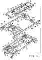
- a bed apparatus as shown in FIG. 1 includes a base 1 of a rectangular frame.
- the base 1 has stopper-equipped casters 2 at four corners on its lower surface.
- a pair of brackets 3 are provided uprightly in those opposed side positions of the base 1 at each end of a longitudinal direction such that one pair of brackets 3 are located in a corresponding relation to the other pair of brackets 3 as viewed in a width direction as shown in FIG. 3.
- a pair of rotation shafts 5 constituting a raising/lowering link mechanism 4 are rotatably spanned on each pair of brackets 3.
- a pair of levers 6 are fixed at one end to the end portions of the respective rotation shafts 5.
- a support shaft 7 is fixed at an end portion to the other end sides of the levers 6 in a respective pair.
- a roller 8 is rotatably provided on each extreme end of the respective support shaft 7.
- a first arm 9 is fixed at a one-end side to an intermediate portion of one rotation shaft 5 and a second arm 11 is fixed at its intermediate portion to the intermediate portion of the other rotation shaft 5.
- One and the other end of an interlocking rod 12 are pivotally mounted on the other end of the first arm 9 and one downwardly attending end of the second arm 11, respectively.
- a raising/lowering drive mechanism 13 is provided on the upper surface of an intermediate portion of an interlocking rod 12.
- the raising/lowering drive mechanism 13 comprises a drive source 14 swingably mounted on the interlocking rod 12 and a drive shaft 15 driven by the drive source 14 in back and forth motion and the forward end of the drive shaft 15 is pivotally mounted on the other end of the second arm 11.
- the second arm 11 When the drive shaft 15 is driven in a projecting direction with the operation of the raising/lowering drive mechanism 13, the second arm 11 is rotated in a counterclockwise direction as indicated by an arrow a in FIG. 1 in interlock with the one rotation shaft 5. With the rotation of the second arm 11, the inter-locking rod 12 is slidably moved in a direction as indicated by an arrow b in FIG. 1 to allow the first arm 9 to he rotated in a counterclockwise direction as indicated by an arrow c in FIG. 1.
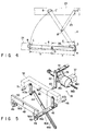
- FIG. 11 shows a state in which the rest frame 21 is raised over the base 1.
- connection link 23 In order to prevent the raised rest frame 21 from being freely moved along a longitudinal direction through the contact of the rollers with the guide rails, one end and other end of a connection link 23 are rotatably connected to the rest frame 21 and lever 6 as shown in FIG. 3.
- the connection link 23 inhibits the rest frame 21 with the rolls 8 supported in the guide rails 22 from being freely moved in a horizontal direction.
- the detaching of the connection link 23 enables the rest frame 21 to be detached from the base 1.
- the rest frame 21 can be raised and lowered in the horizontal state without involving a horizontal slide motion and hence is neither tilted nor has its longitudinal end abutted against a wall surface.
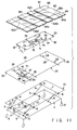
- a rectangular support frame 25 larger than the rest frame 21 is detachably fixed to the upper surface of the rest frame 21.
- the support frame 25 has three lateral rods 26 provided along the width direction and longitudinal rods 28 mounted by connection members 27 on both the ends of the respective lateral rods as shown in FIGS. 2 and 3.
- An abutting plate 28a made of a resin is provided on the upper surface of the longitudinal area of the respective longitudinal rod 28.
- a pair of receiving members 29 are uprightly provided on the opposed end portions of the pair of lateral rods 26 which in turn are each provided on both the longitudinal end portions of the support frame 25.
- the receiving member 29 has arcuate recess 29a one opened at its top side and one at its inside surface side.
- a rotation frame 32 is provided relative to and between the pair of longitudinal rods 28 of the support fame 25.
- a pair of support rollers 33 are rotatably mounted one at each end face of the respective longitudinal section of the rotation frame 32. The respective support roller 33 is engaged with the associated recess 29a in the receiving member 29.
- connection bracket 30 is provided on end portions of each of the pair of longitudinal rods 28 of the support frame 25 such that the connection bracket 30 depends from its fixed upper end portion.
- the lower end portion of the respective connection bracket 30 is detachably mounted at each of four corners of the rest frame 21 as shown in FIG. 1.
- the support frame 25 is moved in interlock with the up/down motion of the rest frame 21.
- a pair of mounting rods 34 are spanned between the pair of lateral rods 26 one at one longitudinal end portion and one at the intermediate portion of the support frame 25 as shown in FIGS. 2, 3 and 6.
- An auxiliary lateral rod 26a is spanned between the intermediate portions of the mounting rods 34 in a parallel relation to the lateral rod 26.
- a rotation drive means 35 is provided relative to these rod members 26, 26a and 34 to allow the rotation frame 32 to be rotated in a right/left direction.
- the rotation drive means 35 is so constructed as shown in FIGS. 5 to 8.
- a bracket 36 is provided at the lower surface side of the one-side mounting rod 34 as shown in FIG. 6 and a drive source 37 has its one end pivotally mounted on a bracket 36.
- the drive source 37 comprises a motor 38a, a screw shaft 38b rotated through the rotation of the motor 38a, and a movable body 38c movable along the screw shaft 38b.
- a pair of first links 39 of an L shape are pivotably mounted at one end to the movable body 38c to provide a link mechanism 40A as shown in FIG. 5.
- the first link 39 is fixed at the other end to a support shaft 41.
- the support shaft 41 is rotatably spanned on brackets 40 which are mounted upright on the one-side lateral rod 26 and auxiliary lateral rod 26a as shown in FIGS. 5 and 6.
- One end portion of the support shaft 41 is projected from the one-side bracket 40 toward the other-side lateral rod 26 side.
- One end of a second link 42 which is straight, is fixed to the projecting end of the support shaft 41.
- An interlocking pin 43 is provided on the other end of the second link 42 and projected there. The interlocking pin 43 is slidably engaged with elongated holes 44a and 45a extending from one end side to an intermediate area side of the third and fourth links 44 and 45, respectively, and cannot be slipped out of these elongated holes.
- connection pin 46 is pivotally mounted on the other end side of the third and fourth links 44 and 45 as shown in FIG. 5.
- One-end sides of connection links 47a, 47b and one side faces of retaining members 49, 49 are pivotally mounted on the connection pins 46, 46 with the retaining members 49, 49 fixed to both end portions of a steady link 48.
- the other-end sides of the connection links 47a, 47b are pivotally mounted on both end portions of the rotation frame 32 in a width direction on one longitudinal end of the rotation frame 32.
- connection links 47a, 47b and support rollers 33, 33 on both the ends of the rotation frame 32 are mounted on the rotation frame 32 by means of an associated pin 51 as shown in FIGS. 6 and 7 (see 47b).
- Substantially L-shaped steady grooves 50 are provided, as engaging means, on the other side faces of the retaining members 49 and opened at one-end face side and lower end face side situated inside in the width direction of the support frame 25.
- An engaging pin 52 serving as a engaging body is projected from the other-side lateral rod 26 toward the auxiliary lateral rod 26a and slidably engaged with the steady groove 50 of the retaining member 49 as shown in FIGS. 7 and 9.
- a distance L1 between the engaging pins 52 is made somewhat greater than a distance between those open ends of the pair of steady grooves 50 but made smaller than a distance L2 between the extreme ends of the steady groove 50.
- the paired engaging pins 52 are engaged with the associated steady grooves 50 of the retaining members 49 so that the rotation frame 32 is held in a steady state without being shaken in a right/left direction. That is, since the rotation frame 32 is rotatably supported by a link mechanism 40, it is unavoidable that, when the link mechanism 40A is not in a driven state, that is, the rotation frame 32 is in the horizontal state, shaking occurs in the rotation direction due to a play at the respective link.
- the movable body 38c of the drive source 37 When, in FIG. 8, the movable body 38c of the drive source 37 is driven in a direction of an arrow A, the first link 39 is rotated in a direction of an arrow B and, in this case, it is done in interlock with the second link 42, the interlocking pin 43 provided at the other-end side of the second link 42 is engaged with the upper end of the elongated hole 45a of the fourth link 45 to allow the link 45 to be rotated in a raised direction of an arrow D in FIG. 8 and, at the same time, the interlocking pin 43 is slidably moved along the elongated hole 44a in the third link 44a.
- the steady link 48 is also moved in slide motion in the horizontal direction as indicated by an arrow C.
- the steady groove 50 of the one side retaining member 49 situated on the upper end side of the fourth ring 45 is allowed to be disengaged from the one side engaging pin 52 and the other side engaging pin 52 is relatively moved in slide motion toward the extreme end side of the steady groove 50 of the other side retaining member 49.
- connection links 47a, 47b As indicated by a phantom line in FIG. 8, that is, the rotation frame 32 has its other-end side raised over the support frame 25 with the support rollers 33, that is, rollers 33 supported in the associated recesses 29a of the receiving members 29 on the one-end side of the rotation frame 32 in a width direction, as their fulcrums.
- the interlocking pin 43 With further driving of the first links 39 from that state, the interlocking pin 43 is upwardly moved in slide motion into abutting contact with the extreme end of the elongated hole 44a in the third link 44 to push the third link 44 in a direction of an arrow E in FIG. 8.
- the steady link 48 slides in a horizontal direction reverse to the arrow C to allow the one side engaging pin 52 to be brought back into engagement with the steady groove 50 of one side retaining member 49. That is, the rotation frame 32 is held in a horizontal state without being shaken in the right/left direction.
- the third link 44 is upwardly moved in a raised direction and the rotation frame 32 can be rotated with its width-direction other-end side as a fulcrum.
- a bed plate structure 61 is disposed on the upper side of the support frame 25 and rotation frame 32.
- the bed plate structure 61 comprises, as shown in FIGS. 10A and 10B, a middle bed plate assembly 62 having a size substantially corresponding to that of the rotation frame 32 and a pair of side bed plate assemblies 64 connected, by hinges 63 as will be set out below, to both sides of the middle bed plate assembly such that these side bed plate assemblies 64 can be rotated only in the raised direction.
- the respective bed plate assemblies 62 and 64 are provided in plural members, that is, as first to fourth bed plates 62a to 62d and 64a to 64d, respectively, in the present embodiment.
- the bed plates of the respective bed plate assemblies 62 and 64 are placed over four mounting frames 65a to 65d sequentially connected in a rotatable manner.
- the respective bed plates 62a to 62d of the middle bed plate assembly 62 are fixed to the mounting frames 65a to 65d.
- the floor plates 62a to 62d of the side bed plate assembly 62 are place over the mounting frames 65a to 65d to allow them to be rotated upwardly.
- the respective bed plates 62a to 62d and 64a to 64d are provided as an integral structure by blow-molding the middle bed plate assembly 62 and paired side bed plate assemblies 64 with a synthetic resin.
- the middle bed plate assembly 62 and paired side bed plate assemblies 64 are formed as a hollow structure having a predetermined thickness.
- the top ends of the middle bed plates and those of the side bed plates as viewed in their thickness direction are connected, as an integral structure, by thinned areas serving as hinges 63.
- the side bed plate assemblies 64 can be rotated relative to the middle bed plate assembly 62 in a raised direction as indicated by a phantom line in FIG. 10B and the rotation of the side bed plates in a down direction is restricted by the the abutting contact of the side bed plate ends with the adjacent ends of the middle bed plates.
- a plurality of air ports 66 are provided at the respective bed plates of the middle and side bed plate assemblies at the time of blow molding to penetrate through their thickness. By doing so, the bed plate structure 61 allows air to pass through the air ports in the thickness direction.
- the bed plates 62a to 62d and 64a to 64d are formed of two kinds of molding units differing in their size. A pair of juxtaposed molding units are placed at each longitudinal ends of the bed plate structure and two molding units of different size are placed between one pair of juxtaposed molding units at one end and the other pair of juxtaposed molding units on the other end of the bed plate structure.
- the rotation frame 32 When the rotation frame 32 is rotated by the rotation drive means 35 and, at this time, it is done in interlock with the middle bed plate assembly 62 in the bed plate structure 61, the one side bed plate 64 situated on the "raised” side is maintained on the same plane as the middle a bed plate assembly 62 while the other side bed plate assembly 64 situated on the lower end side is abutted against the abutting plate 28a provided on the side area of the support frame 25 so that the upward bending is made at a predetermined angle while preventing the downward rotation.
- a user lying on the bed plate structure 61 has his or her body position moved or raised in a right/left direction by the rotation of the middle bed plate assembly 62 in the right/left direction at which time the lying user is prevented from dropping out of the bed plate structure 61 by the bending of the side bed plate assembly toward the upper side of the middle bed plate assembly 62.
- rollers may be employed in place of the abutting plates 28a in which case bending is achieved by the abutting of the side bed plate assembly 64 against the rollers.
- a raising/lowering motion drive mechanism 71 is provided at the intermediate portion of the length of the rotation frame 32 to raise and lower the bed plates 62a, and 64a of the bed plate assemblies 62 and 64 in the bed plate structure 61 as shown in FIG. 3.
- the drive mechanism 71 comprises a box 72 incorporating a built-in power transmission mechanism, not shown, a pair of drive sources 73 provided one at each of side surfaces of the box 72, a first rotation shaft 74 provided on one end portion of the box 72 in a manner to extend through the opposed side portions of the box and adapted to be rotated by one of the paired drive sources 73 and a second rotation shaft 75 provided on the other end portion of the box 72 and extend through the opposed side portion of the box 72. Both the ends of each of the first and second rotation shafts 74 and 75 are rotatably supported by associated brackets 76.
- First push-up arms 77 are fixed at one end to both the end portions of the first rotation shaft 74 and second push-up arms 78 are fixed at one end to both the end portions of the second rotation shaft 75.
- the other end portions of each of the push-up arms 77 and 78 are rotatably mounted on associated roller 79.
- the rollers 79 on the first push-up arms 77 are placed in rolling contact with the mounting frame 65a mounted on the bed plate 62a of the middle bed plate assembly 62 as shown in FIG. 10A and the rollers 79 on the second push-up arms 78 placed in rolling contact with the mounting frame 65c of the third bed plate 62c of the middle bed plate assembly 62.
- the first rotation shaft 74 is rotated to allow the first push-up arms 77 to be rotated in the raised direction, the first bed plate 62a of the middle bed plate assembly 62 is moved up in the "raised” direction and, in this case, it is done in interlock with the first bed plate 64a of the side bed plate assembly 64.
- the third bed plate 62c of the middle bed plate assembly 62 is rotated in a "raised” direction and it is done in interlock with the fourth bed plate 62d and bending is achieved in an upwardly convex dogleg-like manner.
- the corresponding bed plates 64c and 64d of the side bed plate assemblies 64 are also moved in interlocking manner.
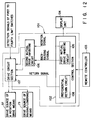
- the rotation drive means 35 and raising/lowering drive means 71 are driven by a control device 101 as shown in FIG. 12.
- the control device 101 has a control section 102 comprised of a CPU.
- a remote controller 103 is connected to the control section 102.
- a command signal for driving the drive means 35 and drive means 71 is input to the control section 102 by the remote controller 103.
- a display unit 104 is connected to the control section 102 and the command signal selected by the remote controller 103 can be displayed, in graphics form, on the display unit 104.
- the remote controller 103 can select an automatic operation and manual operation upon the rotation motion of the bed plate structure 61 and set the rotation motion angle, rotation motion cycle, etc., of the rotation operation.
- the control section 102 delivers a rotation signal and back-raising signal from the control section 102.
- a first mutual drive inhibiting circuit 105 is provided in the control section 102 to inhibit the simultaneous outputting of both the rotation motion signal and back-raising signal.
- the drive circuit section 107 outputs a drive signal for driving the drive source 37 of the rotation drive means 35 and a drive signal for driving the pair of drive sources 73 of the raising/lowering motion drive means 71. By doing so, it is possible to effect the rotation motion drive and raising/lowering motion drive of the bed plate structure 61.
- the control section 102 includes a preferential return circuit 108 for allowing the bed plate structure 61 to be driven from a raised state preferentially to a lying-down state in advance of the rotation motion drive and raising/lowering drive motion of the bed plate structure 61.
- a return signal from the preferential return circuit 108 is input to the drive circuit section 107.
- a drive signal is output from the drive circuit section 107 to cause the bed plate structure 61 to be driven in a direction toward a lying-down position. By doing so, the bed plate structure 61 causes the bed plate structure 61 to be driven in the lying-down direction by the drive source 73 of the drive means 71.
- An initial state (horizontal state) at a time of rotating the bed plate structure 61 and initial state (flat state) at a time of raising/lowering the bed plate structure 61 are detected as shown in models in FIGS. 13A and 13B. That is, the former initial state is detected by first and second limit switches 111 and 112 provided on both width-direction ends at the lower surface of the middle bed plate assembly 62 of the bed plate structure 61. That is, with the bed plate structure 61 in a not-rotated horizontal state, the first and second limit switches 111 and 112 are pushed down by the rotation frame 32, that is, the rotation frame supporting the middle bed plate assembly 62, and placed in an ON state. With the bed plate structure 61 in the latter state (flat state), any one of these limit switches is turned ON and the other limit switch OFF.
- the initial state at a time of raising/lowering the bed plate structure 61 is detected by third and fourth limit switches 113 and 114, that is, the third limit switch 113 turned ON by being pushed by the first push-up arm 77 for raising/lowering the first bed plate 62a when the first bed plate 62a is in the horizontal sate and the fourth limit switch 114 turned ON by being pushed by the second push-up arm 78 for raising/lowering the third bed plate 62c when the third bed plate 62c is in the horizontal state. That is, when the first bed plate 62a or the third bed plate 62c is raised from the flat state, the third or the fourth limit switch is placed in the OFF state.
- the detection signals from the first to fourth limit switches 111 to 114 are input to the first mutual drive inhibiting circuit 106.
- the first and second mutual drive inhibiting circuits 105 and 106 inhibit the rotation signal or the back-raising signal from being input to the drive circuit section 107, so that the bed plate structure 61 is driven in the other state. Further, if the bed plate structure 61 is to be placed both in the rotating state and in the raising state, it is driven neither in a rotating state nor in the raising state.
- the bed plate structure 61 provided over the support frame 25 allows three operations: an up/down motion, a rolling motion in the width direction and a partial raising/lowering bed motion.
- the raising/lowering drive mechanism 13 is operated, driving the drive shaft 15 in a projected direction.
- the levers 6 are raised from the lying-down state through the pair of rotation shafts 5 connected at both the end portions to the levers 6 so that the rest frame 21 can be raised with the rotation of the levers 6.
- the rotation frame 32 with the bed plate structure 32 placed thereon is provided over the upper side of the rest frame 21 with the support frame 25 interposed, these are raised as one unit.
- the height level of the bed plate structure can readily be adjusted.
- the bed plate structure 61 can be made adequately low so that he or she can readily be get into or out of the bed plate structure.
- the drive source 37 of the rotation drive means 35 is operated to drive the link mechanism 40A.
- the link mechanism 40A enables the third link 44 or fourth link 45 to be driven in the raised direction in accordance with the direction in which the movable body 38c of the drive source 37 is operated.
- the rotation frame 32 With the fourth link 45 driven in the raised direction, the rotation frame 32 has its width-direction other-end side raised with the roller 51, that is, the roller engaged with the recess 29a of the receiving member 29 on the width-direction one-end side, as a fulcrum.
- the bed plate structure 61 is operated in an interlocking manner. That is, the bed plate structure 61 has its middle bed plate assembly's other-end side is raised with the width-direction one-end side as a fulcrum as indicated by a phantom line in FIG. 8.
- the one side bed plate assembly 64 connected to the width-direction one-end side of the bed plate structure has its lower surface abutted against the abutting plate 28a of the support frame 25 so that the one side bed plate assembly is bent upwardly.
- the side bed plate assembly 64 connected to the other-end side of the bed plate structure is interlockingly moved in the same plane as that of the middle bed plate assembly 62.
- the rotation frame 32 can be rotated in a direction reverse to that set out above.
- the middle bed plate assembly 62 of the bed plate structure 61 can be rotated by the rotation frame 23 in an alternate right/left motion.
- any user lying on the bed plate structure 61 can experience his or her body position change in the right/left direction.
- Any user needing a long-term confinement in bed such as an ill or an elderly person, can prevent an onset of a bedsore.
- the side bed plate assembly 64 connected to the width-direction one-end side, that is, the base end side, of the rotating middle bed plate assembly 62 is bent upwardly to provide an upwardly convex surface so that the user is prevented from dropping out of the bed plate structure when he or she experiences any body position change in the right or left direction.
- the middle bed plate assembly 62 has the other-end side driven in the raised direction with the width-direction one-end side as a fulcrum. For this reason, the width-direction one-end side, that is, the lower end side, of the rotating middle bed plate assembly 62 is not displaced to a height level substantially lower than any support height level of the bed plate structure 61 and the middle bed plate assembly 62 can be rotated in such a manner. Even if the support height of the bed plate structure 61 is made enough low, the user can experience his or her body position change by rotating the middle bed plate assembly 62 in the right/left direction.
- the support height of the bed plate structure is made enough low, the user, such as an ill or an elderly person in particular, can readily get into and out of the bed plate structure 61 without the help of any attendant or caretaker.
- the paired engaging pins 52 on the support frame 25 engage with the associated steady grooves 50 at the retaining member 49 provided on the rotation frame 32 side so that the rotation frame 32 is prevented from being shaken in the right/left direction.
- the bed apparatus is used with the rotation frame assembly 23 in the horizontal state, then the bed user never will suffer any discomfort which would other wise been involved due to the shaking of the bed frame structure 61 in the right/left direction. That is, even if the rotation frame 32 is so structured as to be rotated by the link mechanism 40a, the rotation frame 23 can be prevented from being shaken.
- the engaging pins 52 are automatically brought into and out of engagement with the associated steady grooves 50 through the operation of the link mechanism 40A. For this reason, no specific extra operation is necessary and the bed apparatus is easier in operation and very advantageous.
- the raising/lowering motion drive mechanism 71 is operated with the bed plate structure 61 in the horizontal position. That is, the paired drive source 73 is operated to enable the first and second rotation shafts 74 and 75 to be rotated at which time the push-up arms 77 and 78 are moved in an inter-locking manner.
- the first bed plate 62a of the middle bed plate assembly 62 is raised as indicated by the phantom line in FIG. 1 and the first bed plates 64a of the paired side bed plate assemblies 64 are moved interlockingly so that the bed user can have his or her upper body half moved to a raised position.
- the second push-up arms 78 driven in the raised direction, the third bed plate 62c of the middle bed plate assembly 62 is rotated with one end connected to the second bed plate 62b acting as a fulcrum, that is, rotated at the other end side in a raised direction so that the fourth bed plate 62d connected to the other-end side of the third bed plate is raised on its one-end side.
- the third bed plate 62c and fourth bed plate 62d are bent in an upwardly convex, substantially dogleg-like manner and the third and fourth bed plates 64c and 64d of the paired side bed plates 64 are moved in an interlocking manner.
- the user having his or her upper body half raised, is held in an upwardly leg-bent position by the third bed plates 62c and 64c and fourth bed plates 62d and 64d so that he or she can be held in upper half body-raised position comfortably and at ease.
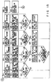
- step S1 With reference to a flow chart in FIGS. 14 and 15, explanation will be given below about the control under which the bed plate 61 is driven in rotation motion and in raising/lowering motion.
- the preferential return circuit 108 in the control section 102 outputs a return signal to the drive circuit section 107 and, by the return signal, the drive source 73 of the drive means 71 drives the bed plate structure 61 preferentially in a lying-down direction.
- step S4 it is decided whether or not, at step S4, the bed plate structure 61 is in the rotating state and, if it is in the rotating state, the rotation angle of the bed plate structure 61 is returned back to a zero angle state in step S5. That is, a rotation signal is output from the control section 102 and the drive source 37 of the rotation drive means 35 drives the bed plate structure 61 to set the latter to a zero rotation angle.
- the first mutual drive inhibiting circuit 105 in the control section 102 and second mutual drive inhibiting circuit 106 outside the control circuit 102 inhibit the bed plate 61 from being driven either in the raising/lowering state or in the rotating state.
- control section 102 includes the preferential return circuit 108, even if the first to fourth limit switches 111 to 114 for detecting the rotating state and raising/lowering state of the bed plate structure 61 detect the rotating state and raising state of the bed plate structure 61, the bed plate structure is driven preferentially from the raised state to the initial laying-down state by the return signal from the preferential return circuit 108.
- step S5 When, at step S5, the bed plate structure 61 is returned back to both the flat and horizontal state, an automatic operation is done in an initially set automatic operation mode at step S5. That is, in order to prevent the onset of a bedsore in the bed user, the bed plate structure 61 is driven in rotation motion at an initially set rotation angle and rotation cycle.
- step S7 it is decided whether or not the bed plate structure 61 is in the rotating state at a step S8 and, if the bed plate structure 61 is in the rotating state, the bed plate structure 61 is driven to the flat state at step S9. Then it is decided whether or not the bed plate structure 61 is in the lying-down (flat) state at step S10. If the bed plate structure 61 is in the not flat (raised) state, it is driven in the lying-down position as shown in step S11 and the automatic operation cycle is ended.
- step S1 If, on the other hand, the manual operation is selected at step S1, four kinds of operations as shown in FIG. 15 can be selected by push buttons on the remote controller 103.
- step S12 in the case where the bed plate structure 61 is set in the lying down state from the raised state as a first manual operation shown in step S12, the bed plate structure 61 is caused to be driven preferentially in the laying down direction. This is shown in step S13. Then it is decided whether or not the bed plate structure 61 is in the lying down (flat) position and, if YES, that operation is ended.
- the bed plate structure 61 is set from the rotated state back to a horizontal state, it is caused to be driven preferentially in the lying down direction as shown at step S16 by a corresponding command signal from the preferential return circuit 108.
- step S17 it is decided whether or not the bed plate structure 61 is set in the lying down (flat) state and, if it is confirmed as being flat, the bed plate structure 61 is driven in the horizontal direction by the drive source 37 of the rotation drive means 35 as shown in S18.
- step S19 it is decided whether or not the bed plate structure 61 be set in a horizontal state. If YES, a second manual operation is ended.
- the bed plate structure 61 is driven from its flat state toward a raised direction as shown in step S20, it is driven by a corresponding command signal toward the horizontal state as shown in step S21. It is decided, at step 22, whether or not the bed plate structure 61 is set horizontal and, if YES, the bed plate structure 61 is driven in a raised direction at step 23.
- the bed plate structure 61 is rotated as shown in step S24, it is caused to be driven, by the preferential return circuit 108, preferentially toward the lying down (flat) position as shown in step S25. It is decided, at step S26, whether or not the bed plate structure 61 be set in the flat position. If YES, the rotation operation of the bed plate structure 61 is started as shown in step S27.
- Step 28 corresponds to a manual operation stop command whereby, as shown in step S29, the manually operated bed plate structure 61 can be stopped at a predetermined raising angle or a rotation angle.
- the bed plate structure 61 is driven from the raised state, by the preferential return circuit 108, preferentially toward the lying down state even in the presence of the first and second mutual drive inhibiting circuits 105 and 106.
- the raised state of the bed plate structure 61 is released and the driving of the bed plate structure 61 is inhibited by the first and second mutual drive inhibiting circuits 105 and 106 under the control circuit. It is, therefore, possible to effect the raising operation and rotating operation of the bed plate structure 61.
- the first mutual drive inhibiting circuit 105 is provided in the control section 102 and the second mutual drive inhibiting circuit 106 is provided outside the control section 102. For this reason, even if either one of these two mutual drive inhibiting circuits are erroneously operated, the other mutual drive inhibiting circuit serves as a back-up circuit so that the bed plate structure 61, being in a raising state, can be positively prevented from being driven in a rotating state.
- the first mutual drive inhibiting circuit 105 in the control section 102 has a risk of being erroneously operated due to noise generated in the control section 102. It is, however, possible to, even under the operation error of the first mutual drive inhibiting circuit 105, positively prevent the raising bed plate structure 61 from being rotated by the second mutual drive inhibiting circuit 106.
- the present invention is not restricted to the above-mentioned embodiment and can be variously changed or modified without departing from the spirit and scope of the present invention.
- the mutual drive inhibiting circuits are provided one inside and one outside the control section, for example, it may be provided on either one of these sides.
Abstract
Description
- The present invention relates to a bed apparatus effective to prevent development of any bedsore in a bed user especially, such as a fed-ridden ill or elderly person.
- The patient, being unable to turn in a bed or raise his or her own body, has to be kept confined to the fed for a prolonged period of time. The bed user, continuing his or her supine position over a prolonged period, has suffered a so-called "bedsore" and experiences greater pain in him or her. In order to prevent such bedsore, the patient has to properly rotate his or her position by varying a bed plate in a width direction. Bed apparatuses having such a rotation function have been developed.
- Another bed apparatus equipped with the raising/lowering function has been known. In this bed apparatus, the bed plate has such a structure as to allow its portion to be driven in a freely raising/lowering manner, so that the bed user, being unable to raise his or her torso under his or her own, can eat and read in a raised bed plate or maintain his or her torso comfortably in a raised bed plate. In recent years, a bed apparatus has been developed which has both the rotation function and the raising/lowering function.
- The bed apparatus, equipped with both the rotation function and the raising/lowering function, usually includes a base on which a rest frame is so placed as to be movable in an up/drown direction. The base is of such a type that a support frame is mounted thereon and that a rotation frame is rotatably mounted on the support frame with a bed plate structure provided on the rotation frame.
- The bed plate structure has a middle bed plate assembly and side bed plate assemblies provided one at each side of the middle bed plate assembly in which case these bed plate assemblies are rotatable only in an upward direction. The respective bed plate assemblies are divided into a plurality of bed plates each having a predetermined length in a longitudinal direction and connected to be rotatable.
- Of the plurality of bed plates in the middle bed plate assembly, one is fixed to the rotation frame. The rotation frame has a width dimension smaller than that of the bed plate structure. Further, the support frame has its width dimension set to be greater than the rotation frame and smaller than the bed plate structure.
- The support frame includes a rotation drive mechanism for rotationally driving the rotation frame in a width direction and the rotation frame has a raising/lowering drive mechanism to allow the bed plate in the bed plate structure to be driven in a raising/lowering direction.
- When the rotation frame is rotationally driven by the rotation drive mechanism in a width direction, the bed plate structure is driven in an interlocking relation. At that time, one side bed plate assembly at a lower side in a rotation direction abuts against the upper surface of one side of the support frame and rotated upward, so that the user in a supine position can be prevented from falling on the bedside.
- In the bed apparatus thus constructed, the bed plate structure bendably rotating in a width direction cannot be raised and lowered in the longitudinal direction, while, on the other hand, the bed plate structure in a raising/lowering state cannot be rotated in the width direction. When the bed plate structure in one of the rotating state and raising/lowering state is driven toward the other state, an undue force is applied to the bed plate structure, so that the bed plate structure and drive mechanism are sometimes caused to damage.
- In that case, the usual practice is to prevent the bed plate structure in one of these two states from being driven toward the other state. That is, whether the bed plate structure is in the rotating state or in the raising/lowering state is detected by a corresponding limit switch. If either one of these states taken by the bed plate structure is detected by the limit switch, then a control circuit effects such control as to prevent the bed plate structure from being driven toward the other state, that is, from being driven in both these states.
- That is, the limit switch detects whether or not the middle bed plate assembly of the bed plate structure is in a horizontal state (a zero-rotation-angle state) and whether or not the raising/lowering angle of the respective bed plates is set at a zero raising/lowering angle.
- In the case where the rotation angle of the middle bed plate and raising/lowering angle of the respective bed plates are detected by the limit switches, a detection error sometimes occurs due to a load on the middle bed plate assembly or on the respective bed plates being varied through the movement of the bed user's body weight.
- In the case where the bed plate structure in the rotated state (inclined state) is driven in a horizontal direction, if the bed user's body weight is moved, for example, through the rolling of his or her body in the bed in the rotating direction of the bed plate structure, then the middle bed plate assembly is bent, so that, just before the middle bed plate is set to the horizontal state, the limit switch is sometimes turned ON by the bent middle bed plate assembly to stop the rotation of the bed plate structure.
- In such a state, if the bed plate structure is electrically detected by the limit switch as being horizontal, it is possible to set the bed plate structure in a raised/lowered state. If, however, there arises a variation in a distribution of a load inflicted by the user on the middle bed plate assembly due to the raising/ lowering of the bed plate structure, then the limit switch, being turned ON upon rotation of the bed plate structure, is sometimes rendered OFF.
- Since, in this case, the bed plate structure is detected as being not only in a raising state but also in the rotating state, these operations are immediately stopped by the control circuit, that is, the mutual drive inhibiting control circuit. Even if, thereafter, the rotation or raising/lowering operation is to be restarted, the bed plate structure is detected by the respective limit switch's signals as both in a rotating state and in the raising/lowering state and the bed plate structure is moved neither to a rotating state nor to a raising/lowering state under the control circuit.
- The present invention is achieved based on the above-mentioned situations and it is accordingly the object of the present invention to provide a bed apparatus which, even if a bed plate structure is to be stopped both in a rotating state and in a raising state, enables an intended operation to be performed through a control circuit without involving any non-operation.
- In one preferred embodiment of the present invention as claimed in
claim 1, a bed apparatus is provided, characterized in that - a support frame;
- a rotation frame having a one-end side and other-end side supported on the support frame in a width direction so that one of these end sides each serving as a fulcrum is rotatable in a direction in which an opposite-end side of the rotation frame is raised;
- rotation drive means having a rotation link mechanism connected to the rotation frame and a first drive source provided on the support frame and adapted to drive the rotation link mechanism, the rotation drive means rotating the rotation frame by driving the rotation link mechanism by the first drive source;
- a bed plate structure having a middle bed plate assembly and a pair of side bed plate assemblies provided one at each side of the middle bed plate assembly and connected to be rotatable only in an upward direction, the middle bed plate assembly and side bed plate assemblies being divided into a plurality of rotatably connected bed plates and provided on the rotation frame, at least one bed plate of the middle bed plate assembly being fixed to the rotation frame and the remaining bed plates capable of being raised/lowered, and the bed plate structure being such that, with the rotation driving of the rotation frame, one of these side plate assemblies on a lower side in the rotation direction is abutted against the support frame to allow the bed plate structure to be bent upward;
- raising/lowering drive means provided on the rotation frame and having a second drive source for driving a portion of the bed plate structure to be raised/lowered in a longitudinal direction; and
- a control device controlling the driving of the first drive source of the rotation drive means and second drive source of the raising/lowering drive means, wherein
the control device comprises:- a control section connected to receive a command signal for driving the respective drive sources and generate an output signal based on the command signal;
- mutual drive inhibiting means for inhibiting the first drive source and second drive source from being driven together; and
- preferential return means operating the first drive source and adapted to allow the second drive source to be operated before the rotation driving of the bed plate structure and the bed plate structure to be returned back to an initial not-raised state.
- This invention can be more fully understood from the following detailed description when taken in conjunction with the accompanying drawings, in which:
- FIG. 1 is a front view generally showing an arrangement of a bed apparatus according to one embodiment of the present invention;
- FIG. 2 is a plan view, partly taken away, showing a support frame in the bed apparatus;
- FIG. 3 is an exploded, perspective view showing a base, support frame and rotation frame;
- FIG. 4 is an explanative view showing a rest frame of the bed apparatus when it is raised;
- FIG. 5 is an exploded, perspective view showing part of a link mechanism of a rotation drive means in the bed apparatus;
- FIG. 6 is a plan view showing the rotation drive means in the bed apparatus;
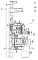
- FIG. 7 is a side view showing the rotation drive means;
- FIG. 8 is a front view showing the rotation drive means in the bed apparatus;
- FIG. 9 is an enlarged, front view showing a steady link in the bed apparatus;
- FIG. 10A is a plan view as viewed from a lower surface side of a bed plate structure in the apparatus bed;
- FIG. 10B is an enlarged, cross-sectional view, taken along line XB-XB in FIG. 10A;
- FIG. 11 is an exploded, perspective view diagrammatically showing a whole arrangement in the bed apparatus;
- FIG. 12 is a block diagram showing a control device in the bed apparatus;
- FIG. 13A is an arrangement of limit switches for detecting a rotating state of the bed plate structure;
- FIG. 13B is an arrangement of the limit switches for detecting a raised state of the bed plate structure;
- FIG. 14 is a flow chart for explaining a portion of an operation of the bed apparatus; and
- FIG. 15 is a flow chart for explaining a portion of an operation of the bed apparatus.
- A bed apparatus according to an embodiment of the present invention will be explained below with reference to the accompanying drawings.
- A bed apparatus as shown in FIG. 1 includes a
base 1 of a rectangular frame. Thebase 1 has stopper-equippedcasters 2 at four corners on its lower surface. A pair ofbrackets 3 are provided uprightly in those opposed side positions of thebase 1 at each end of a longitudinal direction such that one pair ofbrackets 3 are located in a corresponding relation to the other pair ofbrackets 3 as viewed in a width direction as shown in FIG. 3. A pair ofrotation shafts 5 constituting a raising/loweringlink mechanism 4 are rotatably spanned on each pair ofbrackets 3. A pair oflevers 6 are fixed at one end to the end portions of therespective rotation shafts 5. Asupport shaft 7 is fixed at an end portion to the other end sides of thelevers 6 in a respective pair. Aroller 8 is rotatably provided on each extreme end of therespective support shaft 7. - A
first arm 9 is fixed at a one-end side to an intermediate portion of onerotation shaft 5 and asecond arm 11 is fixed at its intermediate portion to the intermediate portion of theother rotation shaft 5. One and the other end of an interlockingrod 12 are pivotally mounted on the other end of thefirst arm 9 and one downwardly attending end of thesecond arm 11, respectively. A raising/loweringdrive mechanism 13 is provided on the upper surface of an intermediate portion of an interlockingrod 12. The raising/loweringdrive mechanism 13 comprises adrive source 14 swingably mounted on the interlockingrod 12 and adrive shaft 15 driven by thedrive source 14 in back and forth motion and the forward end of thedrive shaft 15 is pivotally mounted on the other end of thesecond arm 11. - When the
drive shaft 15 is driven in a projecting direction with the operation of the raising/loweringdrive mechanism 13, thesecond arm 11 is rotated in a counterclockwise direction as indicated by an arrow a in FIG. 1 in interlock with the onerotation shaft 5. With the rotation of thesecond arm 11, theinter-locking rod 12 is slidably moved in a direction as indicated by an arrow b in FIG. 1 to allow thefirst arm 9 to he rotated in a counterclockwise direction as indicated by an arrow c in FIG. 1. - With the first and
second arms levers 6 connected to the respective arms are rotated from a lying-down position to a raising position as shown in FIG. 3. -
Rollers 8 at both the ends of thesupport shafts 7 connected to therespective levers 6 are placed in rollable contact with corresponding u-cross-sectional guide rails 22 provided at the inner surface of opposed sides of arectangular rest frame 21. With the pairedlevers 6 rotated in a raising direction, therest frame 21 is raised through therollers 8. FIG. 11 shows a state in which therest frame 21 is raised over thebase 1. - In order to prevent the raised
rest frame 21 from being freely moved along a longitudinal direction through the contact of the rollers with the guide rails, one end and other end of aconnection link 23 are rotatably connected to therest frame 21 andlever 6 as shown in FIG. 3. Theconnection link 23 inhibits therest frame 21 with therolls 8 supported in the guide rails 22 from being freely moved in a horizontal direction. The detaching of theconnection link 23 enables therest frame 21 to be detached from thebase 1. - With A, B and C representing a rotation support point, a longitudinal midpoint and the other end of the lever (the roller-mount side end) 6, respectively, and D representing the other end of the
connection link 23 as shown in FIG. 4, the lengths AB, BD, BD and BC are set to AB=BD and BD=BC. In consequence, a triangle defined by the three points A, B and D and that defined by the three points B, C and D become isosceles triangles. - If the points A, B, C and D are shifted to points A', B', C' and D' as indicated by a phantom line in FIG. 4 as in the case where the
rest frame 21 is moved to a raised position, then an angle defined by the three points A', B' and D' and that defined by the three points B', C' and D' become isosceles triangles. - When the
lever 6 is rotated from the lying-down position toward the raised direction, the respective triangles maintain their isosceles triangle and the other end D side of theconnection link 23 is raised to the point D' in a vertical direction as indicated by an arrow V in FIG. 4. Further, the points C and D, while maintaining substantially the same height in a horizontal direction, are upwardly shifted to the points C' and D'. - As a result, the
rest frame 21 can be raised and lowered in the horizontal state without involving a horizontal slide motion and hence is neither tilted nor has its longitudinal end abutted against a wall surface. - A
rectangular support frame 25 larger than therest frame 21 is detachably fixed to the upper surface of therest frame 21. Thesupport frame 25 has threelateral rods 26 provided along the width direction andlongitudinal rods 28 mounted byconnection members 27 on both the ends of the respective lateral rods as shown in FIGS. 2 and 3. An abutting plate 28a made of a resin is provided on the upper surface of the longitudinal area of the respectivelongitudinal rod 28. - A pair of receiving
members 29 are uprightly provided on the opposed end portions of the pair oflateral rods 26 which in turn are each provided on both the longitudinal end portions of thesupport frame 25. The receivingmember 29 has arcuate recess 29a one opened at its top side and one at its inside surface side. - A
rotation frame 32 is provided relative to and between the pair oflongitudinal rods 28 of thesupport fame 25. A pair ofsupport rollers 33 are rotatably mounted one at each end face of the respective longitudinal section of therotation frame 32. Therespective support roller 33 is engaged with the associated recess 29a in the receivingmember 29. - A
connection bracket 30 is provided on end portions of each of the pair oflongitudinal rods 28 of thesupport frame 25 such that theconnection bracket 30 depends from its fixed upper end portion. The lower end portion of therespective connection bracket 30 is detachably mounted at each of four corners of therest frame 21 as shown in FIG. 1. Thesupport frame 25 is moved in interlock with the up/down motion of therest frame 21. - A pair of mounting
rods 34 are spanned between the pair oflateral rods 26 one at one longitudinal end portion and one at the intermediate portion of thesupport frame 25 as shown in FIGS. 2, 3 and 6. An auxiliary lateral rod 26a is spanned between the intermediate portions of the mountingrods 34 in a parallel relation to thelateral rod 26. A rotation drive means 35 is provided relative to theserod members rotation frame 32 to be rotated in a right/left direction. - The rotation drive means 35 is so constructed as shown in FIGS. 5 to 8. A
bracket 36 is provided at the lower surface side of the one-side mounting rod 34 as shown in FIG. 6 and adrive source 37 has its one end pivotally mounted on abracket 36. Thedrive source 37 comprises a motor 38a, ascrew shaft 38b rotated through the rotation of the motor 38a, and a movable body 38c movable along thescrew shaft 38b. - A pair of
first links 39 of an L shape are pivotably mounted at one end to the movable body 38c to provide alink mechanism 40A as shown in FIG. 5. Thefirst link 39 is fixed at the other end to asupport shaft 41. Thesupport shaft 41 is rotatably spanned onbrackets 40 which are mounted upright on the one-side lateral rod 26 and auxiliary lateral rod 26a as shown in FIGS. 5 and 6. - One end portion of the
support shaft 41 is projected from the one-side bracket 40 toward the other-side lateral rod 26 side. One end of asecond link 42, which is straight, is fixed to the projecting end of thesupport shaft 41. An interlockingpin 43 is provided on the other end of thesecond link 42 and projected there. The interlockingpin 43 is slidably engaged with elongated holes 44a and 45a extending from one end side to an intermediate area side of the third andfourth links - One end side of the
connection pin 46 is pivotally mounted on the other end side of the third andfourth links connection links 47a, 47b and one side faces of retainingmembers members steady link 48. The other-end sides of theconnection links 47a, 47b are pivotally mounted on both end portions of therotation frame 32 in a width direction on one longitudinal end of therotation frame 32. - The other-end sides of the
connection links 47a, 47b andsupport rollers rotation frame 32 are mounted on therotation frame 32 by means of an associatedpin 51 as shown in FIGS. 6 and 7 (see 47b). - Substantially L-shaped
steady grooves 50 are provided, as engaging means, on the other side faces of the retainingmembers 49 and opened at one-end face side and lower end face side situated inside in the width direction of thesupport frame 25. An engagingpin 52 serving as a engaging body is projected from the other-side lateral rod 26 toward the auxiliary lateral rod 26a and slidably engaged with thesteady groove 50 of the retainingmember 49 as shown in FIGS. 7 and 9. As shown in FIG. 9, a distance L1 between the engaging pins 52 is made somewhat greater than a distance between those open ends of the pair ofsteady grooves 50 but made smaller than a distance L2 between the extreme ends of thesteady groove 50. - With the
rotation frame 32 in a horizontal state, the paired engagingpins 52 are engaged with the associatedsteady grooves 50 of the retainingmembers 49 so that therotation frame 32 is held in a steady state without being shaken in a right/left direction. That is, since therotation frame 32 is rotatably supported by alink mechanism 40, it is unavoidable that, when thelink mechanism 40A is not in a driven state, that is, therotation frame 32 is in the horizontal state, shaking occurs in the rotation direction due to a play at the respective link. - When, however, the
rotation frame 32 is in the horizontal state, the paired engagingpins 52 are engaged with the associatedsteady grooves 50 of the retainingmembers 49 and therotation frame 32 is prevented from being shaken in the right/left direction. - When, in FIG. 8, the movable body 38c of the
drive source 37 is driven in a direction of an arrow A, thefirst link 39 is rotated in a direction of an arrow B and, in this case, it is done in interlock with thesecond link 42, the interlockingpin 43 provided at the other-end side of thesecond link 42 is engaged with the upper end of the elongated hole 45a of thefourth link 45 to allow thelink 45 to be rotated in a raised direction of an arrow D in FIG. 8 and, at the same time, the interlockingpin 43 is slidably moved along the elongated hole 44a in the third link 44a. - When the
fourth link 45 starts its rotation, thesteady link 48 is also moved in slide motion in the horizontal direction as indicated by an arrow C. As a result, thesteady groove 50 of the oneside retaining member 49 situated on the upper end side of thefourth ring 45 is allowed to be disengaged from the oneside engaging pin 52 and the otherside engaging pin 52 is relatively moved in slide motion toward the extreme end side of thesteady groove 50 of the otherside retaining member 49. - When this occurs, the
steady link 49 is brought to a state of rotation with the otherside engaging pin 52 as a fulcrum so that thesteady link 48 is rotated in interlock with thefourth link 45. - With the rotation of the
steady link 48, therotation frame 32 is moved in interlock motion through theconnection links 47a, 47b as indicated by a phantom line in FIG. 8, that is, therotation frame 32 has its other-end side raised over thesupport frame 25 with thesupport rollers 33, that is,rollers 33 supported in the associated recesses 29a of the receivingmembers 29 on the one-end side of therotation frame 32 in a width direction, as their fulcrums. - When, with the
rotation frame 32 in a tilted state, thefirst links 39 are rotated in a direction reverse to the arrow B to drive the movable body 38c of thedrive source 37 in a direction reverse to the arrow A, therotation frame 32 andsteady link 48 are rotated toward a lying-down direction. With thesteady link 48 is lowered to a substantially horizontal state to allow the oneside engaging pin 52 to abut against the opened lower face 50a (FIG. 9) of thesteady groove 50 of the retainingmember 49. With further driving of thefirst links 39 from that state, the interlockingpin 43 is upwardly moved in slide motion into abutting contact with the extreme end of the elongated hole 44a in thethird link 44 to push thethird link 44 in a direction of an arrow E in FIG. 8. As a result, thesteady link 48 slides in a horizontal direction reverse to the arrow C to allow the oneside engaging pin 52 to be brought back into engagement with thesteady groove 50 of oneside retaining member 49. That is, therotation frame 32 is held in a horizontal state without being shaken in the right/left direction. - If, from this state, the movable body 38c of the
drive source 39 is driven in an opposite direction, that is, in a direction reverse to the arrow A, thethird link 44 is upwardly moved in a raised direction and therotation frame 32 can be rotated with its width-direction other-end side as a fulcrum. - A
bed plate structure 61 is disposed on the upper side of thesupport frame 25 androtation frame 32. Thebed plate structure 61 comprises, as shown in FIGS. 10A and 10B, a middlebed plate assembly 62 having a size substantially corresponding to that of therotation frame 32 and a pair of sidebed plate assemblies 64 connected, byhinges 63 as will be set out below, to both sides of the middle bed plate assembly such that these sidebed plate assemblies 64 can be rotated only in the raised direction. - The respective
bed plate assemblies bed plate assemblies frames 65a to 65d sequentially connected in a rotatable manner. The respective bed plates 62a to 62d of the middlebed plate assembly 62 are fixed to the mountingframes 65a to 65d. The floor plates 62a to 62d of the sidebed plate assembly 62 are place over the mountingframes 65a to 65d to allow them to be rotated upwardly. - Of the respective bed plates, only the
bed plates 62b of the middlefloor plate assembly 62 is detachably fixed to therotation frame 32 and the other bed plates are simply place over therotation frame 32. - As shown in FIG. 10B, the respective bed plates 62a to 62d and 64a to 64d are provided as an integral structure by blow-molding the middle
bed plate assembly 62 and paired sidebed plate assemblies 64 with a synthetic resin. The middlebed plate assembly 62 and paired sidebed plate assemblies 64 are formed as a hollow structure having a predetermined thickness. The top ends of the middle bed plates and those of the side bed plates as viewed in their thickness direction are connected, as an integral structure, by thinned areas serving as hinges 63. - The side
bed plate assemblies 64 can be rotated relative to the middlebed plate assembly 62 in a raised direction as indicated by a phantom line in FIG. 10B and the rotation of the side bed plates in a down direction is restricted by the the abutting contact of the side bed plate ends with the adjacent ends of the middle bed plates. - A plurality of
air ports 66 are provided at the respective bed plates of the middle and side bed plate assemblies at the time of blow molding to penetrate through their thickness. By doing so, thebed plate structure 61 allows air to pass through the air ports in the thickness direction. - The bed plates 62a to 62d and 64a to 64d are formed of two kinds of molding units differing in their size. A pair of juxtaposed molding units are placed at each longitudinal ends of the bed plate structure and two molding units of different size are placed between one pair of juxtaposed molding units at one end and the other pair of juxtaposed molding units on the other end of the bed plate structure.
- When the
rotation frame 32 is rotated by the rotation drive means 35 and, at this time, it is done in interlock with the middlebed plate assembly 62 in thebed plate structure 61, the oneside bed plate 64 situated on the "raised" side is maintained on the same plane as the middle abed plate assembly 62 while the other sidebed plate assembly 64 situated on the lower end side is abutted against the abutting plate 28a provided on the side area of thesupport frame 25 so that the upward bending is made at a predetermined angle while preventing the downward rotation. - By doing so, a user lying on the
bed plate structure 61 has his or her body position moved or raised in a right/left direction by the rotation of the middlebed plate assembly 62 in the right/left direction at which time the lying user is prevented from dropping out of thebed plate structure 61 by the bending of the side bed plate assembly toward the upper side of the middlebed plate assembly 62. - For the
support frame 25, rollers, not shown, may be employed in place of the abutting plates 28a in which case bending is achieved by the abutting of the sidebed plate assembly 64 against the rollers. - A raising/lowering
motion drive mechanism 71 is provided at the intermediate portion of the length of therotation frame 32 to raise and lower the bed plates 62a, and 64a of thebed plate assemblies bed plate structure 61 as shown in FIG. 3. Thedrive mechanism 71 comprises abox 72 incorporating a built-in power transmission mechanism, not shown, a pair ofdrive sources 73 provided one at each of side surfaces of thebox 72, afirst rotation shaft 74 provided on one end portion of thebox 72 in a manner to extend through the opposed side portions of the box and adapted to be rotated by one of the paireddrive sources 73 and asecond rotation shaft 75 provided on the other end portion of thebox 72 and extend through the opposed side portion of thebox 72. Both the ends of each of the first andsecond rotation shafts brackets 76. - First push-up
arms 77 are fixed at one end to both the end portions of thefirst rotation shaft 74 and second push-uparms 78 are fixed at one end to both the end portions of thesecond rotation shaft 75. The other end portions of each of the push-uparms roller 79. - The
rollers 79 on the first push-uparms 77 are placed in rolling contact with the mountingframe 65a mounted on the bed plate 62a of the middlebed plate assembly 62 as shown in FIG. 10A and therollers 79 on the second push-uparms 78 placed in rolling contact with the mountingframe 65c of thethird bed plate 62c of the middlebed plate assembly 62. - When, with the
roller 79 placed in rolling contact with the mountingframes first rotation shaft 74 is rotated to allow the first push-uparms 77 to be rotated in the raised direction, the first bed plate 62a of the middlebed plate assembly 62 is moved up in the "raised" direction and, in this case, it is done in interlock with the first bed plate 64a of the sidebed plate assembly 64. - When the
second rotation shaft 75 is rotated to allow the second push-uparms 78 to be rotated in a "raised" direction, thethird bed plate 62c of the middlebed plate assembly 62 is rotated in a "raised" direction and it is done in interlock with thefourth bed plate 62d and bending is achieved in an upwardly convex dogleg-like manner. With the rotations of the third andfourth bed plates bed plate assembly 62, the correspondingbed plates bed plate assemblies 64 are also moved in interlocking manner. - The rotation drive means 35 and raising/lowering drive means 71 are driven by a
control device 101 as shown in FIG. 12. Thecontrol device 101 has acontrol section 102 comprised of a CPU. A remote controller 103 is connected to thecontrol section 102. A command signal for driving the drive means 35 and drive means 71 is input to thecontrol section 102 by the remote controller 103. Adisplay unit 104 is connected to thecontrol section 102 and the command signal selected by the remote controller 103 can be displayed, in graphics form, on thedisplay unit 104. - The remote controller 103 can select an automatic operation and manual operation upon the rotation motion of the
bed plate structure 61 and set the rotation motion angle, rotation motion cycle, etc., of the rotation operation. - The
control section 102 delivers a rotation signal and back-raising signal from thecontrol section 102. A first mutualdrive inhibiting circuit 105 is provided in thecontrol section 102 to inhibit the simultaneous outputting of both the rotation motion signal and back-raising signal. - The rotation motion signal and back-raising signal delivered from the
control section 102, being input to a second mutualdrive inhibiting circuit 106 provided outside thecontrol section 102, are output to adrive circuit section 107. That is, even in the case where both the rotation motion signal and back-raising signal are simultaneously to be output due to an operation error caused by noise, etc., in thecontrol section 102 in spite of the presence of the first mutualdrive inhibiting circuit 105 in thecontrol section 102, these two signals are not simultaneously output to thedrive circuit section 107 due to the presence of the second mutualdrive inhibiting circuit 106. - The
drive circuit section 107 outputs a drive signal for driving thedrive source 37 of the rotation drive means 35 and a drive signal for driving the pair ofdrive sources 73 of the raising/lowering motion drive means 71. By doing so, it is possible to effect the rotation motion drive and raising/lowering motion drive of thebed plate structure 61. - The
control section 102 includes apreferential return circuit 108 for allowing thebed plate structure 61 to be driven from a raised state preferentially to a lying-down state in advance of the rotation motion drive and raising/lowering drive motion of thebed plate structure 61. A return signal from thepreferential return circuit 108 is input to thedrive circuit section 107. A drive signal is output from thedrive circuit section 107 to cause thebed plate structure 61 to be driven in a direction toward a lying-down position. By doing so, thebed plate structure 61 causes thebed plate structure 61 to be driven in the lying-down direction by thedrive source 73 of the drive means 71. - An initial state (horizontal state) at a time of rotating the
bed plate structure 61 and initial state (flat state) at a time of raising/lowering thebed plate structure 61 are detected as shown in models in FIGS. 13A and 13B. That is, the former initial state is detected by first andsecond limit switches 111 and 112 provided on both width-direction ends at the lower surface of the middlebed plate assembly 62 of thebed plate structure 61. That is, with thebed plate structure 61 in a not-rotated horizontal state, the first andsecond limit switches 111 and 112 are pushed down by therotation frame 32, that is, the rotation frame supporting the middlebed plate assembly 62, and placed in an ON state. With thebed plate structure 61 in the latter state (flat state), any one of these limit switches is turned ON and the other limit switch OFF. - The initial state at a time of raising/lowering the
bed plate structure 61 is detected by third andfourth limit switches third limit switch 113 turned ON by being pushed by the first push-uparm 77 for raising/lowering the first bed plate 62a when the first bed plate 62a is in the horizontal sate and thefourth limit switch 114 turned ON by being pushed by the second push-uparm 78 for raising/lowering thethird bed plate 62c when thethird bed plate 62c is in the horizontal state. That is, when the first bed plate 62a or thethird bed plate 62c is raised from the flat state, the third or the fourth limit switch is placed in the OFF state. - The detection signals from the first to fourth limit switches 111 to 114 are input to the first mutual
drive inhibiting circuit 106. - That is, when any of the respective limit switches detects any one of the rotating state and raising state of the
bed plate structure 61, the first and second mutualdrive inhibiting circuits drive circuit section 107, so that thebed plate structure 61 is driven in the other state. Further, if thebed plate structure 61 is to be placed both in the rotating state and in the raising state, it is driven neither in a rotating state nor in the raising state. - The operation of the bed apparatus thus arrange will be explained below.
- The
bed plate structure 61 provided over thesupport frame 25 allows three operations: an up/down motion, a rolling motion in the width direction and a partial raising/lowering bed motion. - For the up/down motion, the raising/lowering
drive mechanism 13 is operated, driving thedrive shaft 15 in a projected direction. As a result, thelevers 6 are raised from the lying-down state through the pair ofrotation shafts 5 connected at both the end portions to thelevers 6 so that therest frame 21 can be raised with the rotation of thelevers 6. - Since the
rotation frame 32 with thebed plate structure 32 placed thereon is provided over the upper side of therest frame 21 with thesupport frame 25 interposed, these are raised as one unit. In the case where any action has to be given to a lying patient on thebed plate structure 61 for beside care or medical examination, the height level of the bed plate structure can readily be adjusted. Further, when the patient has to climb into or out of thebed plate structure 61, thebed plate structure 61 can be made adequately low so that he or she can readily be get into or out of the bed plate structure. - In order to rotate the
bed plate structure 61, thedrive source 37 of the rotation drive means 35 is operated to drive thelink mechanism 40A. Thelink mechanism 40A enables thethird link 44 orfourth link 45 to be driven in the raised direction in accordance with the direction in which the movable body 38c of thedrive source 37 is operated. - With the
fourth link 45 driven in the raised direction, therotation frame 32 has its width-direction other-end side raised with theroller 51, that is, the roller engaged with the recess 29a of the receivingmember 29 on the width-direction one-end side, as a fulcrum. - When the
rotation frame 32 has its other-end side raised with the width-direction one-end side as a fulcrum, thebed plate structure 61 is operated in an interlocking manner. That is, thebed plate structure 61 has its middle bed plate assembly's other-end side is raised with the width-direction one-end side as a fulcrum as indicated by a phantom line in FIG. 8. As a result, the one sidebed plate assembly 64 connected to the width-direction one-end side of the bed plate structure has its lower surface abutted against the abutting plate 28a of thesupport frame 25 so that the one side bed plate assembly is bent upwardly. On the other hand, the sidebed plate assembly 64 connected to the other-end side of the bed plate structure is interlockingly moved in the same plane as that of the middlebed plate assembly 62. - If the
drive source 37 is so operated as to drive thethird link 44 in the raised direction, therotation frame 32 can be rotated in a direction reverse to that set out above. - If, therefore, the direction in which the movable body 38c is driven by the
drive source 37 is varied, for example, for each predetermined time, then the middlebed plate assembly 62 of thebed plate structure 61 can be rotated by therotation frame 23 in an alternate right/left motion. - In the case where the middle
bed plate assembly 62 is rotated, for each predetermined time, in an alternate right/left motion, any user lying on thebed plate structure 61 can experience his or her body position change in the right/left direction. Any user needing a long-term confinement in bed, such as an ill or an elderly person, can prevent an onset of a bedsore. Further, the sidebed plate assembly 64 connected to the width-direction one-end side, that is, the base end side, of the rotating middlebed plate assembly 62 is bent upwardly to provide an upwardly convex surface so that the user is prevented from dropping out of the bed plate structure when he or she experiences any body position change in the right or left direction. - In the case where the user lying on the
bed plate structure 61 thus experience his or her body position change, the middlebed plate assembly 62 has the other-end side driven in the raised direction with the width-direction one-end side as a fulcrum. For this reason, the width-direction one-end side, that is, the lower end side, of the rotating middlebed plate assembly 62 is not displaced to a height level substantially lower than any support height level of thebed plate structure 61 and the middlebed plate assembly 62 can be rotated in such a manner. Even if the support height of thebed plate structure 61 is made enough low, the user can experience his or her body position change by rotating the middlebed plate assembly 62 in the right/left direction. - In the case where the user experiences his or her body position change with the middle
bed plate assembly 62 rotated in the right or in the left direction, if the support height of the bed plate structure is great, the bed occupant feels discomport or ill at ease and it is better, therefore, to achieve the body position change in a low position. - If the support height of the bed plate structure is made enough low, the user, such as an ill or an elderly person in particular, can readily get into and out of the
bed plate structure 61 without the help of any attendant or caretaker. - With the
bed plate structure 61 is in a horizontal position, the paired engagingpins 52 on thesupport frame 25 engage with the associatedsteady grooves 50 at the retainingmember 49 provided on therotation frame 32 side so that therotation frame 32 is prevented from being shaken in the right/left direction. - If the bed apparatus is used with the
rotation frame assembly 23 in the horizontal state, then the bed user never will suffer any discomfort which would other wise been involved due to the shaking of thebed frame structure 61 in the right/left direction. That is, even if therotation frame 32 is so structured as to be rotated by the link mechanism 40a, therotation frame 23 can be prevented from being shaken. - Further, the engaging
pins 52 are automatically brought into and out of engagement with the associatedsteady grooves 50 through the operation of thelink mechanism 40A. For this reason, no specific extra operation is necessary and the bed apparatus is easier in operation and very advantageous. - In order to achieve a "back-raising operation of the
bed plate structure 61, the raising/loweringmotion drive mechanism 71 is operated with thebed plate structure 61 in the horizontal position. That is, the paireddrive source 73 is operated to enable the first andsecond rotation shafts arms - With the first push-up
arm 77 driven in the raised direction, the first bed plate 62a of the middlebed plate assembly 62 is raised as indicated by the phantom line in FIG. 1 and the first bed plates 64a of the paired sidebed plate assemblies 64 are moved interlockingly so that the bed user can have his or her upper body half moved to a raised position. With the second push-uparms 78 driven in the raised direction, thethird bed plate 62c of the middlebed plate assembly 62 is rotated with one end connected to thesecond bed plate 62b acting as a fulcrum, that is, rotated at the other end side in a raised direction so that thefourth bed plate 62d connected to the other-end side of the third bed plate is raised on its one-end side. - That is, the
third bed plate 62c andfourth bed plate 62d are bent in an upwardly convex, substantially dogleg-like manner and the third andfourth bed plates side bed plates 64 are moved in an interlocking manner. The user, having his or her upper body half raised, is held in an upwardly leg-bent position by thethird bed plates fourth bed plates - Further, since the
rest frame 21,support frame 25 andbed plate structure 61 are detachable from thebase 1, these component parts can readily be carried by the user's hand on transportation, etc. - With reference to a flow chart in FIGS. 14 and 15, explanation will be given below about the control under which the
bed plate 61 is driven in rotation motion and in raising/lowering motion. With the power supply of thecontrol device 101 ON as shown in FIG. 14, an automatic or manual operation is selected after a ready mode (step S1). - Where the automatic operation is selected, it is determined whether the
bed plate structure 61 is placed in the lying-down (flat) state or in the raising state as shown at step S2 in FIG. 14. If the bed plate structure is not placed in the lying-down state, it is driven preferentially in the lying-down direction as shown in step S3. That is, thepreferential return circuit 108 in thecontrol section 102 outputs a return signal to thedrive circuit section 107 and, by the return signal, thedrive source 73 of the drive means 71 drives thebed plate structure 61 preferentially in a lying-down direction. - Then, it is decided whether or not, at step S4, the
bed plate structure 61 is in the rotating state and, if it is in the rotating state, the rotation angle of thebed plate structure 61 is returned back to a zero angle state in step S5. That is, a rotation signal is output from thecontrol section 102 and thedrive source 37 of the rotation drive means 35 drives thebed plate structure 61 to set the latter to a zero rotation angle. - If the
bed plate structure 61 is to be placed in the raising state and in the rotating state, the first mutualdrive inhibiting circuit 105 in thecontrol section 102 and second mutualdrive inhibiting circuit 106 outside thecontrol circuit 102 inhibit thebed plate 61 from being driven either in the raising/lowering state or in the rotating state. - Since, however, the
control section 102 includes thepreferential return circuit 108, even if the first to fourth limit switches 111 to 114 for detecting the rotating state and raising/lowering state of thebed plate structure 61 detect the rotating state and raising state of thebed plate structure 61, the bed plate structure is driven preferentially from the raised state to the initial laying-down state by the return signal from thepreferential return circuit 108. - Therefore, there is no possibility that, even if the
bed plate structure 61 is to be placed both in the rotating state and in the raising state, thebed plate structure 61 will not be able to be driven. - When, at step S5, the
bed plate structure 61 is returned back to both the flat and horizontal state, an automatic operation is done in an initially set automatic operation mode at step S5. That is, in order to prevent the onset of a bedsore in the bed user, thebed plate structure 61 is driven in rotation motion at an initially set rotation angle and rotation cycle. - When the automatic operation is ended as shown in step S7, it is decided whether or not the
bed plate structure 61 is in the rotating state at a step S8 and, if thebed plate structure 61 is in the rotating state, thebed plate structure 61 is driven to the flat state at step S9. Then it is decided whether or not thebed plate structure 61 is in the lying-down (flat) state at step S10. If thebed plate structure 61 is in the not flat (raised) state, it is driven in the lying-down position as shown in step S11 and the automatic operation cycle is ended. - If, on the other hand, the manual operation is selected at step S1, four kinds of operations as shown in FIG. 15 can be selected by push buttons on the remote controller 103.
- That is, in the case where the
bed plate structure 61 is set in the lying down state from the raised state as a first manual operation shown in step S12, thebed plate structure 61 is caused to be driven preferentially in the laying down direction. This is shown in step S13. Then it is decided whether or not thebed plate structure 61 is in the lying down (flat) position and, if YES, that operation is ended. - In the case where, as the second manual operation as shown in step S15, the
bed plate structure 61 is set from the rotated state back to a horizontal state, it is caused to be driven preferentially in the lying down direction as shown at step S16 by a corresponding command signal from thepreferential return circuit 108. - At step S17, it is decided whether or not the
bed plate structure 61 is set in the lying down (flat) state and, if it is confirmed as being flat, thebed plate structure 61 is driven in the horizontal direction by thedrive source 37 of the rotation drive means 35 as shown in S18. At step S19, it is decided whether or not thebed plate structure 61 be set in a horizontal state. If YES, a second manual operation is ended. - In the case where, as a third manual operation, the
bed plate structure 61 is driven from its flat state toward a raised direction as shown in step S20, it is driven by a corresponding command signal toward the horizontal state as shown in step S21. It is decided, atstep 22, whether or not thebed plate structure 61 is set horizontal and, if YES, thebed plate structure 61 is driven in a raised direction atstep 23. - In the case where, as the fourth manual operation, the
bed plate structure 61 is rotated as shown in step S24, it is caused to be driven, by thepreferential return circuit 108, preferentially toward the lying down (flat) position as shown in step S25. It is decided, at step S26, whether or not thebed plate structure 61 be set in the flat position. If YES, the rotation operation of thebed plate structure 61 is started as shown in step S27. -
Step 28 corresponds to a manual operation stop command whereby, as shown in step S29, the manually operatedbed plate structure 61 can be stopped at a predetermined raising angle or a rotation angle. - When a predetermined operation command is issued even in the manual operation, it is performed after the
bed plate structure 61 is driven by thepreferential return circuit 108 preferentially toward the lying down direction. - Even if, therefore, the
bed plate structure 61 is to be set forth in the raising state and in the rotating state under the control circuit, thebed plate structure 61 is driven from the raised state, by thepreferential return circuit 108, preferentially toward the lying down state even in the presence of the first and second mutualdrive inhibiting circuits - By doing so, the raised state of the
bed plate structure 61 is released and the driving of thebed plate structure 61 is inhibited by the first and second mutualdrive inhibiting circuits bed plate structure 61. - Further, the first mutual
drive inhibiting circuit 105 is provided in thecontrol section 102 and the second mutualdrive inhibiting circuit 106 is provided outside thecontrol section 102. For this reason, even if either one of these two mutual drive inhibiting circuits are erroneously operated, the other mutual drive inhibiting circuit serves as a back-up circuit so that thebed plate structure 61, being in a raising state, can be positively prevented from being driven in a rotating state. - In particular, the first mutual
drive inhibiting circuit 105 in thecontrol section 102 has a risk of being erroneously operated due to noise generated in thecontrol section 102. It is, however, possible to, even under the operation error of the first mutualdrive inhibiting circuit 105, positively prevent the raisingbed plate structure 61 from being rotated by the second mutualdrive inhibiting circuit 106. - The present invention is not restricted to the above-mentioned embodiment and can be variously changed or modified without departing from the spirit and scope of the present invention. Although the mutual drive inhibiting circuits are provided one inside and one outside the control section, for example, it may be provided on either one of these sides.
Claims (12)
- A bed apparatus characterized in thata support frame (25);a rotation frame (32) having a one-end side and other-end side supported on the support frame in a width direction so that one of these end sides each serving as a fulcrum is rotatable in a direction in which an opposite-end side of the rotation frame (25) is raised;rotation drive means (35) having a rotation link mechanism (40A) connected to the rotation frame (25) and a first drive source (37) provided on the support frame (25) and adapted to drive the rotation link mechanism (40A), the rotation drive means (35) rotating the rotation frame (32) by driving the rotation link mechanism (40A) by the first drive source (37);a bed plate structure (61) having a middle bed plate assembly (62) and a pair of side bed plate assemblies (64) provided one at each side of the middle bed plate assembly and connected to be rotatable only in an upward direction, the middle bed plate assembly (62) and side bed plate assemblies (64) being divided into a plurality of rotatably connected bed plates (62a to 62d, 64a to 60d) and provided on the rotation frame (32), at least one bed plate (62b) of the middle bed plate assembly (62) being fixed to the rotation frame (32) and the remaining bed plates capable of being raised/lowered, and the bed plate structure being such that, with the rotation driving of the rotation frame (32), one of these side plate assemblies (64) on a lower side in the rotation direction is abutted against the support frame (25) to allow the bed plate structure to be bent upward;raising/lowering drive means (71) provided on the rotation frame (32) and having a second drive source (73) for driving a portion of the bed plate structure (61) to be raised/lowered in a longitudinal direction; anda control device (101) controlling the driving of the first drive source (37) of the rotation drive means (35) and second drive source (73) of the raising/lowering drive means (71), wherein
the control device (101) comprises:a control section (102) connected to receive a command signal for driving the respective drive sources (37, 73) and generate an output signal based on the command signal;mutual drive inhibiting means (105, 106) for inhibiting the first drive source (37) and second drive source (73) from being driven together; andpreferential return means (108) operating the first drive source (37) and adapted to allow the second drive source (73) to be operated before the rotation driving of the bed plate structure (61) and the bed plate structure (61) to be returned back to an initial not-raised state. - A bed apparatus according to claim 1, characterized in that the mutual drive inhibiting means (105, 106) is provided inside and outside of the control section (102).
- A bed apparatus according to claim 1, characterized in that the rotation frame (32) includes retaining means for inhibiting the rotation frame (32) from being rotated in a rotated in a rotating direction when the rotation link mechanism (40A) is not driven by the first drive source (37).
- A bed apparatus according to claim 3, characterized in that the retaining means comprises:a steady link (48) connected at both end portions to the link mechanism (40A) and, when the link mechanism (40A) is driven, moving in a longitudinal direction so that, with the one end side situated at a rear end side in that longitudinal direction serving as a fulcrum, the other end side is rotated in a raising direction;a pair of retaining members (49) having a retaining groove opened at a one-end face side and at a lower-end face side and provided at respective longitudinal end portions of the steady link (48) with those one-end face sides of the respective grooves situated in an opposed relation; anda pair of engaging means provided on the support frame (25) and engaged with the retaining grooves (50) to prevent the rotation frame (32) from being rotated in a width direction and, when the steady link (48) is moved by the rotation link mechanism (40A) in the longitudinal direction, disengaged from the one-side steady groove (50) situated on a forward end side in the moving direction.
- A bed apparatus according to claim 1, characterized in that the bed plate structure (61) is molded from a synthetic resin.
- A bed apparatus according to claim 5, characterized in that the bed plate structure (61) is blow-molded from the synthetic resin to provide a hollow bed plate structure.
- A bed apparatus according to claim 6, characterized in that the bed plate structure (61) has air ports as through holes in a thickness direction.
- A bed apparatus according to claim 6, characterized in that the middle plate assembly and side bed assemblies of the bed plate structure (61) are rotatably coupled together by thin-wall portions (63) simultaneously formed at a time of forming the bed plate structure (63).
- A bed apparatus according to claim 1, characterized in that the rotation frame (32) has a pair of rotatable support rollers (33) at each longitudinal end portion at a predetermined interval in a width direction and the support frame (25) has a pair of support receivers (29) having an open recess (29a) at an upper end face where the corresponding support roller (25) is supported in an engaged manner.
- A bed apparatus according to claim 1, characterized in that the support frame (25) is provided on a rest frame (21), the rest frame (21) being provided on a base (1) in such a state as to be driven up and down by a raising/lowering drive mechanism (13).
- A bed apparatus according to claim 10, characterized in that the raising/lowering drive mechanism (13) comprises a raising/lowering link mechanism (4) for raising and lowering the rest frame (21) in a horizontal state without sliding in a horizontal direction and a drive source (14) for operating the raising/lowering link mechanism (4).
- A bed apparatus according to claim 11, characterized in that the raising/lowering link mechanism (4) comprises rotation shafts (5) rotatably provided on the base (1) and rotatably driven by the drive source (14), a lever having an one-end side pivotably mounted on the rotation shaft (5) and having a roller (8) at an other-end side, the roller (8) movably engaged with a corresponding rail (22) provided on the rest frame (21), a connection link (23) set to a length corresponding to one half the lever (6) and having one end pivoted at a longitudinal midpoint of the lever and the other end pivoted to the rest frame (21).
Applications Claiming Priority (3)
| Application Number | Priority Date | Filing Date | Title |
|---|---|---|---|
| JP162052/96 | 1996-06-21 | ||
| JP16205296 | 1996-06-21 | ||
| JP16205296A JP3362097B2 (en) | 1996-06-21 | 1996-06-21 | Bed equipment |
Publications (3)
| Publication Number | Publication Date |
|---|---|
| EP0813853A2 true EP0813853A2 (en) | 1997-12-29 |
| EP0813853A3 EP0813853A3 (en) | 1998-05-13 |
| EP0813853B1 EP0813853B1 (en) | 2002-05-29 |
Family
ID=15747187
Family Applications (1)
| Application Number | Title | Priority Date | Filing Date |
|---|---|---|---|
| EP19960120729 Expired - Lifetime EP0813853B1 (en) | 1996-06-21 | 1996-12-21 | Bed apparatus |
Country Status (3)
| Country | Link |
|---|---|
| EP (1) | EP0813853B1 (en) |
| JP (1) | JP3362097B2 (en) |
| DE (1) | DE69621432T2 (en) |
Cited By (11)
| Publication number | Priority date | Publication date | Assignee | Title |
|---|---|---|---|---|
| EP0951892A2 (en) * | 1998-04-22 | 1999-10-27 | Faram S.p.A. | Bed, particularly for communities, of the type with bed-plane articulated structure and means for the movement and control of at least said bed-plane |
| EP0965320A3 (en) * | 1998-06-18 | 2000-09-06 | Vauth-Sagel GmbH & Co. Grundstücksverwaltung | Patient or nursing bed |
| EP1346668A1 (en) * | 2002-03-18 | 2003-09-24 | Paramount Bed Company Limited | Method of adjustment of a base structure for a bed or the like |
| EP1346669A1 (en) * | 2002-03-18 | 2003-09-24 | Paramount Bed Company Limited | Method of adjustment of a base structure for a bed or the like |
| EP1346666A1 (en) * | 2002-03-18 | 2003-09-24 | Paramount Bed Company Limited | Method of adjustment of a base structure for a bed or the like |
| EP1346667A1 (en) * | 2002-03-18 | 2003-09-24 | Paramount Bed Company Limited | Method of adjustment of a base structure for a bed or the like |
| ES2200663A1 (en) * | 1996-11-11 | 2004-03-01 | Flex Equipos De Descanso Sa | Improved board for placing preferably on bed bases |
| CN106137623A (en) * | 2016-08-08 | 2016-11-23 | 首都医科大学附属北京天坛医院 | Rise and sit Stryker frame |
| CN108524147A (en) * | 2018-04-27 | 2018-09-14 | 江苏赛康医疗设备股份有限公司 | A kind of water-closet bowl driving device and its toilet seat bed |
| CN111166582A (en) * | 2019-12-31 | 2020-05-19 | 肖梅 | Auxiliary turning device for bedridden examination of personnel |
| CN113599152A (en) * | 2021-08-02 | 2021-11-05 | 中国人民解放军空军军医大学 | PICC puts a tub bed |
Families Citing this family (15)
| Publication number | Priority date | Publication date | Assignee | Title |
|---|---|---|---|---|
| JP3638795B2 (en) * | 1998-07-13 | 2005-04-13 | フランスベッド株式会社 | Back-up bed equipment |
| JP2001161757A (en) * | 1999-12-07 | 2001-06-19 | Marutaka Kogyo Kk | Bed |
| JP3357984B2 (en) * | 2000-01-14 | 2002-12-16 | 株式会社椿本チエイン | Electric device for gaddy bed and electric bed |
| JP3715900B2 (en) * | 2001-04-06 | 2005-11-16 | 和夫 大場 | Sleep bed for snoring prevention |
| JP2003010259A (en) * | 2001-07-03 | 2003-01-14 | Kazuo Oba | Snore preventing sound sleep bed |
| JP3862663B2 (en) * | 2002-03-18 | 2006-12-27 | パラマウントベッド株式会社 | Control method for raising and lowering the bottom of a supine table such as a bed |
| CN100340222C (en) * | 2003-12-23 | 2007-10-03 | 郭平安 | Multifunction bed sore preventing health bed |
| JP2005304820A (en) * | 2004-04-22 | 2005-11-04 | Yutaka Denshi Seisakusho:Kk | Roll-over assisting bed |
| JP2006136635A (en) * | 2004-11-15 | 2006-06-01 | Paramount Bed Co Ltd | Bed having a plurality of functions, and method for controlling thereof |
| CN101032440B (en) * | 2007-04-05 | 2011-09-28 | 上海品兴科技有限公司 | Multifunctional turning-over bed |
| EP3756633A1 (en) | 2011-11-22 | 2020-12-30 | Paramount Bed Co., Ltd. | Bed device |
| DE102012217069A1 (en) * | 2012-09-21 | 2014-03-27 | Rössle & Wanner GmbH | Spring suspension with adjusting device |
| JP6353824B2 (en) * | 2015-12-02 | 2018-07-04 | フランスベッド株式会社 | Elevating drive device and bed device |
| EP3574880A4 (en) * | 2017-03-02 | 2021-02-17 | France Bed Co., Ltd. | Bed device |
| JP6550414B2 (en) * | 2017-03-02 | 2019-07-24 | フランスベッド株式会社 | Bed equipment |
Family Cites Families (8)
| Publication number | Priority date | Publication date | Assignee | Title |
|---|---|---|---|---|
| US3763507A (en) * | 1971-08-27 | 1973-10-09 | Miller Herman Inc | Pediatric bed |
| US5479665A (en) * | 1983-09-09 | 1996-01-02 | Cassidy; Joseph P. | Automated tri-fold bed |
| JPH0710601Y2 (en) * | 1990-02-01 | 1995-03-15 | フランスベッド株式会社 | Bed equipment |
| US5299334A (en) * | 1992-01-21 | 1994-04-05 | Kinetic Concepts, Inc. | Hydraulic oscillating treatment table and method |
| GB2272367B (en) * | 1992-11-16 | 1996-01-31 | Hung Yung Feng | A multi-function and automatic sick bed |
| JP2815058B2 (en) * | 1994-02-24 | 1998-10-27 | パラマウントベッド株式会社 | Bed operation control system and operation control method |
| JP2987290B2 (en) * | 1994-05-02 | 1999-12-06 | フランスベッド株式会社 | Bed equipment |
| JPH0880092A (en) * | 1994-09-05 | 1996-03-22 | Toyota Autom Loom Works Ltd | Drive controller of motor |
-
1996
- 1996-06-21 JP JP16205296A patent/JP3362097B2/en not_active Expired - Fee Related
- 1996-12-21 EP EP19960120729 patent/EP0813853B1/en not_active Expired - Lifetime
- 1996-12-21 DE DE1996621432 patent/DE69621432T2/en not_active Expired - Lifetime
Non-Patent Citations (1)
| Title |
|---|
| None |
Cited By (14)
| Publication number | Priority date | Publication date | Assignee | Title |
|---|---|---|---|---|
| ES2200663A1 (en) * | 1996-11-11 | 2004-03-01 | Flex Equipos De Descanso Sa | Improved board for placing preferably on bed bases |
| EP0951892A2 (en) * | 1998-04-22 | 1999-10-27 | Faram S.p.A. | Bed, particularly for communities, of the type with bed-plane articulated structure and means for the movement and control of at least said bed-plane |
| EP0951892A3 (en) * | 1998-04-22 | 2000-05-31 | Faram S.p.A. | Bed, particularly for communities, of the type with bed-plane articulated structure and means for the movement and control of at least said bed-plane |
| EP0965320A3 (en) * | 1998-06-18 | 2000-09-06 | Vauth-Sagel GmbH & Co. Grundstücksverwaltung | Patient or nursing bed |
| EP1346667A1 (en) * | 2002-03-18 | 2003-09-24 | Paramount Bed Company Limited | Method of adjustment of a base structure for a bed or the like |
| EP1346666A1 (en) * | 2002-03-18 | 2003-09-24 | Paramount Bed Company Limited | Method of adjustment of a base structure for a bed or the like |
| EP1346669A1 (en) * | 2002-03-18 | 2003-09-24 | Paramount Bed Company Limited | Method of adjustment of a base structure for a bed or the like |
| EP1346668A1 (en) * | 2002-03-18 | 2003-09-24 | Paramount Bed Company Limited | Method of adjustment of a base structure for a bed or the like |
| CN1302758C (en) * | 2002-03-18 | 2007-03-07 | 八乐梦医用床有限公司 | Lift control method for bottom board of such as bed |
| CN106137623A (en) * | 2016-08-08 | 2016-11-23 | 首都医科大学附属北京天坛医院 | Rise and sit Stryker frame |
| CN108524147A (en) * | 2018-04-27 | 2018-09-14 | 江苏赛康医疗设备股份有限公司 | A kind of water-closet bowl driving device and its toilet seat bed |
| CN111166582A (en) * | 2019-12-31 | 2020-05-19 | 肖梅 | Auxiliary turning device for bedridden examination of personnel |
| CN113599152A (en) * | 2021-08-02 | 2021-11-05 | 中国人民解放军空军军医大学 | PICC puts a tub bed |
| CN113599152B (en) * | 2021-08-02 | 2023-02-07 | 中国人民解放军空军军医大学 | PICC puts a tub bed |
Also Published As
| Publication number | Publication date |
|---|---|
| JP3362097B2 (en) | 2003-01-07 |
| JPH105286A (en) | 1998-01-13 |
| DE69621432T2 (en) | 2003-01-30 |
| EP0813853A3 (en) | 1998-05-13 |
| DE69621432D1 (en) | 2002-07-04 |
| EP0813853B1 (en) | 2002-05-29 |
Similar Documents
| Publication | Publication Date | Title |
|---|---|---|
| EP0813853B1 (en) | Bed apparatus | |
| US5608932A (en) | Articulated bed apparatus | |
| US10470955B2 (en) | Patient bed having translatable siderail for bed exit | |
| US6230344B1 (en) | Adjustable bed | |
| US6789280B1 (en) | Articulated medical bed | |
| US6076209A (en) | Articulation mechanism for a medical bed | |
| US5127113A (en) | Invalid transfer arrangement | |
| US3593350A (en) | Retractable bed | |
| US7426760B2 (en) | Bariatric bed apparatus and methods | |
| US3686696A (en) | Hospital beds | |
| EP1541108A1 (en) | Movable bed | |
| US6691348B2 (en) | Bed with adjustable positions | |
| JP2923412B2 (en) | Bed equipment | |
| JP2006340962A (en) | Electric bed | |
| JP2018143354A (en) | Bed device | |
| JP3012779B2 (en) | Bed equipment | |
| JP3740743B2 (en) | Lift control device for electric lift bed | |
| JP3710694B2 (en) | Wake-up bed equipment | |
| JPH03277315A (en) | Bed appliance | |
| JP3506571B2 (en) | Bed equipment | |
| JP2003111804A (en) | Bed device | |
| JP2019110976A (en) | Bed device | |
| JP2923444B2 (en) | Wake-up bed equipment | |
| JPH0718720U (en) | Bed device with floor tilt mechanism | |
| JPH0740977B2 (en) | Bed equipment |
Legal Events
| Date | Code | Title | Description |
|---|---|---|---|
| PUAI | Public reference made under article 153(3) epc to a published international application that has entered the european phase |
Free format text: ORIGINAL CODE: 0009012 |
|
| 17P | Request for examination filed |
Effective date: 19961221 |
|
| AK | Designated contracting states |
Kind code of ref document: A2 Designated state(s): DE |
|
| PUAL | Search report despatched |
Free format text: ORIGINAL CODE: 0009013 |
|
| AK | Designated contracting states |
Kind code of ref document: A3 Designated state(s): DE ES |
|
| 17Q | First examination report despatched |
Effective date: 20001204 |
|
| GRAG | Despatch of communication of intention to grant |
Free format text: ORIGINAL CODE: EPIDOS AGRA |
|
| GRAG | Despatch of communication of intention to grant |
Free format text: ORIGINAL CODE: EPIDOS AGRA |
|
| GRAH | Despatch of communication of intention to grant a patent |
Free format text: ORIGINAL CODE: EPIDOS IGRA |
|
| RBV | Designated contracting states (corrected) |
Designated state(s): DE |
|
| GRAH | Despatch of communication of intention to grant a patent |
Free format text: ORIGINAL CODE: EPIDOS IGRA |
|
| GRAA | (expected) grant |
Free format text: ORIGINAL CODE: 0009210 |
|
| AK | Designated contracting states |
Kind code of ref document: B1 Designated state(s): DE |
|
| REF | Corresponds to: |
Ref document number: 69621432 Country of ref document: DE Date of ref document: 20020704 |
|
| PLBE | No opposition filed within time limit |
Free format text: ORIGINAL CODE: 0009261 |
|
| STAA | Information on the status of an ep patent application or granted ep patent |
Free format text: STATUS: NO OPPOSITION FILED WITHIN TIME LIMIT |
|
| 26N | No opposition filed |
Effective date: 20030303 |
|
| PGFP | Annual fee paid to national office [announced via postgrant information from national office to epo] |
Ref country code: DE Payment date: 20150112 Year of fee payment: 19 |
|
| REG | Reference to a national code |
Ref country code: DE Ref legal event code: R119 Ref document number: 69621432 Country of ref document: DE |
|
| PG25 | Lapsed in a contracting state [announced via postgrant information from national office to epo] |
Ref country code: DE Free format text: LAPSE BECAUSE OF NON-PAYMENT OF DUE FEES Effective date: 20160701 |