EP0810002A1 - Suction catheter with preformed tip - Google Patents
Suction catheter with preformed tip Download PDFInfo
- Publication number
- EP0810002A1 EP0810002A1 EP97201581A EP97201581A EP0810002A1 EP 0810002 A1 EP0810002 A1 EP 0810002A1 EP 97201581 A EP97201581 A EP 97201581A EP 97201581 A EP97201581 A EP 97201581A EP 0810002 A1 EP0810002 A1 EP 0810002A1
- Authority
- EP
- European Patent Office
- Prior art keywords
- suction inlet
- catheter
- suction
- distal end
- lumen
- Prior art date
- Legal status (The legal status is an assumption and is not a legal conclusion. Google has not performed a legal analysis and makes no representation as to the accuracy of the status listed.)
- Granted
Links
Images


Classifications
-
- A—HUMAN NECESSITIES
- A61—MEDICAL OR VETERINARY SCIENCE; HYGIENE
- A61M—DEVICES FOR INTRODUCING MEDIA INTO, OR ONTO, THE BODY; DEVICES FOR TRANSDUCING BODY MEDIA OR FOR TAKING MEDIA FROM THE BODY; DEVICES FOR PRODUCING OR ENDING SLEEP OR STUPOR
- A61M25/00—Catheters; Hollow probes
- A61M25/0067—Catheters; Hollow probes characterised by the distal end, e.g. tips
- A61M25/0068—Static characteristics of the catheter tip, e.g. shape, atraumatic tip, curved tip or tip structure
-
- A—HUMAN NECESSITIES
- A61—MEDICAL OR VETERINARY SCIENCE; HYGIENE
- A61M—DEVICES FOR INTRODUCING MEDIA INTO, OR ONTO, THE BODY; DEVICES FOR TRANSDUCING BODY MEDIA OR FOR TAKING MEDIA FROM THE BODY; DEVICES FOR PRODUCING OR ENDING SLEEP OR STUPOR
- A61M25/00—Catheters; Hollow probes
- A61M25/0021—Catheters; Hollow probes characterised by the form of the tubing
- A61M25/0041—Catheters; Hollow probes characterised by the form of the tubing pre-formed, e.g. specially adapted to fit with the anatomy of body channels
-
- A—HUMAN NECESSITIES
- A61—MEDICAL OR VETERINARY SCIENCE; HYGIENE
- A61M—DEVICES FOR INTRODUCING MEDIA INTO, OR ONTO, THE BODY; DEVICES FOR TRANSDUCING BODY MEDIA OR FOR TAKING MEDIA FROM THE BODY; DEVICES FOR PRODUCING OR ENDING SLEEP OR STUPOR
- A61M1/00—Suction or pumping devices for medical purposes; Devices for carrying-off, for treatment of, or for carrying-over, body-liquids; Drainage systems
- A61M1/84—Drainage tubes; Aspiration tips
- A61M1/85—Drainage tubes; Aspiration tips with gas or fluid supply means, e.g. for supplying rinsing fluids or anticoagulants
-
- A—HUMAN NECESSITIES
- A61—MEDICAL OR VETERINARY SCIENCE; HYGIENE
- A61M—DEVICES FOR INTRODUCING MEDIA INTO, OR ONTO, THE BODY; DEVICES FOR TRANSDUCING BODY MEDIA OR FOR TAKING MEDIA FROM THE BODY; DEVICES FOR PRODUCING OR ENDING SLEEP OR STUPOR
- A61M25/00—Catheters; Hollow probes
- A61M25/0067—Catheters; Hollow probes characterised by the distal end, e.g. tips
- A61M25/0068—Static characteristics of the catheter tip, e.g. shape, atraumatic tip, curved tip or tip structure
- A61M2025/0073—Tip designed for influencing the flow or the flow velocity of the fluid, e.g. inserts for twisted or vortex flow
Definitions
- the invention relates to a suction catheter comprising a tube-like basic body with a proximal and a distal end inside of which at least a discharge lumen extends. The distal end is connected with a suction inlet of the catheter.
- Such a suction catheter is known. It is used for instance to remove blood thrombi from the bloodstream of a patient. When using the known catheter it is sometimes difficult for the physician carrying out the procedure to position the suction inlet at the target position inside the bloodstream of the patient.
- the preformed, curved and pliable tip facilitates using the suction catheter also when larger blood vessels such as the pulmonary artery are concerned.
- the preformed curved tip also prevents the distal end of the catheter from entering smaller blood vessels.
- the measure as set out in claim 4 is employed.
- the catheter can then be guided by means of a guide wire.
- the measure as set out in claim 5 can in addition be employed in an advantageous manner.
- the guide-wire-lumen extends substantially only in the end-section, so that in the section of the basic body extending from the proximal end to the suction inlet no space is taken up by the guide-wire-lumen. Consequently the discharge lumen can be given a maximum cross-section.
- the invention may be employed in a very suitable manner with a suction catheter as has been characterised in claim 6.
- the catheter 1 illustrated in figure 1 comprises a basic body 2, in which, at a distance from the distal end, a suction inlet 4 has been formed.
- This suction inlet 4 is connected with a discharge lumen, which extends form this opening 4 in the proximal direction to the proximal end of the catheter.
- There the discharge lumen 3 opens into a discharge connection 10.
- a preformed, curved and pliable tip 5 extends in the distal direction to the distal end.
- the curve is of the pigtail-type.
- the tip 5 is curved in the direction in which the suction inlet 4 is pointing.
- the suction inlet 4 is at all times kept at a certain distance from the wall of a blood vessel into which the catheter has been introduced.
- the catheter shown in figure 1 is a preferred embodiment wherein the suction action at the suction inlet 4 is effected by means of ejector action.
- a pressure lumen 6 has been arranged inside the basic body 2 which ends close to the relatively distal end of the suction inlet 4, that is to say on the left-hand side in figure 1, in a jet nozzle 7 which is directed in the opposite, proximal direction along the suction inlet in the discharge lumen 3.
- a fluid jet can be directed along the opening 4 by means of the jet nozzle 7, as a result of which suction will be generated at the suction inlet 4 due to the ejector action.
- the material sucked in will be passed along by the liquid released from the jet nozzle 7 through the discharge lumen 3 to the discharge connection 10.
- the pressure lumen 6 is connected to a pressure connection 11.
- the curved tip 5 can be straightened by using a guide wire 13, which is advanced through a guide-wire-lumen 8 arranged for that purpose inside the basic body 2. At the proximal end this guide- wire-lumen 8 is connected with a guide-wire-connection 12.
- connections 10, 11 and 12 in the figures 1 and 4 have only been illustrated schematically.
- a catheter used for the purpose described will have been provided at the proximal end with haemostatic devices in order to prevent undesired leaking out of blood via the lumens of the catheter.
- the catheter 1 with the curved preformed tip 5 can be employed in large blood vessels and even be advanced through the heart 15 into the pulmonary artery. Because of the preformed curve, the suction inlet 4 is positioned in a stable manner as required. The suction inlet 4 cannot attach itself to the wall as it is kept, by means of the curve 5, at a certain distance from the walls of the blood vessel.
- the catheter according to the invention can also be given the embodiment of a 'rapid exchange'-type.
- the guide-wire-lumen extends from an opening in the wall of the basic body 2 positioned at a limited distance from the distal end to the distal end.
- the guide-wire-lumen can be formed in the end-section only in a suitable manner.
- the guide-wire-lumen does not take up any space in the section of the basic body through which the discharge lumen 3 and the pressure lumen 6 extend. These can in that case be given an optimum cross-section for the purpose of ejector action.
- the tip may be connected to the remaining part of the catheter in any suitable manner, for instance by means of glueing or welding.
- the specific shape of the curve may be adapted to the required operative position.
- the tip may have been manufactured in a suitable manner of a plastic material opaque to X-rays, so that the tip can be made properly visible on an X-ray screen.
Abstract
Description
- The invention relates to a suction catheter comprising a tube-like basic body with a proximal and a distal end inside of which at least a discharge lumen extends. The distal end is connected with a suction inlet of the catheter.
- Such a suction catheter is known. It is used for instance to remove blood thrombi from the bloodstream of a patient. When using the known catheter it is sometimes difficult for the physician carrying out the procedure to position the suction inlet at the target position inside the bloodstream of the patient.
- With the suction catheter according to the invention as characterised in claim 1 this drawback has been remedied. The preformed, curved and pliable tip facilitates using the suction catheter also when larger blood vessels such as the pulmonary artery are concerned. The preformed curved tip also prevents the distal end of the catheter from entering smaller blood vessels.
- An advantageous further development has been characterised in claim 2. This measure prevents the suction inlet from attaching itself to the wall of a blood vessel. The preformed curved tip ensures that the suction inlet is kept at a certain distance from the wall of the blood vessels.
- It has been found that the suction catheter as characterised in claim 3 is easy to handle.
- Preferably the measure as set out in claim 4 is employed. The catheter can then be guided by means of a guide wire.
- The measure as set out in
claim 5 can in addition be employed in an advantageous manner. In that case the guide-wire-lumen extends substantially only in the end-section, so that in the section of the basic body extending from the proximal end to the suction inlet no space is taken up by the guide-wire-lumen. Consequently the discharge lumen can be given a maximum cross-section. - The invention may be employed in a very suitable manner with a suction catheter as has been characterised in
claim 6. - The invention will be explained in greater detail below, with reference to the suction catheter according to the invention as illustrated in the figures.
- Figure 1
- illustrates a partly broken away view of a suction catheter according to an embodiment of the invention.
- Figure 2
- shows an enlarged detail indicated by arrow II in figure 1.
- Figure 3
- illustrates a cross-section along the line III-III in figure 2.
- Figure 4
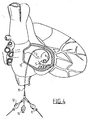
- illustrates schematically the use of the suction catheter.
- The catheter 1 illustrated in figure 1 comprises a basic body 2, in which, at a distance from the distal end, a suction inlet 4 has been formed. This suction inlet 4 is connected with a discharge lumen, which extends form this opening 4 in the proximal direction to the proximal end of the catheter. There the discharge lumen 3 opens into a
discharge connection 10. From the suction inlet 4, a preformed, curved andpliable tip 5 extends in the distal direction to the distal end. The curve is of the pigtail-type. - As can be seen in the figure, the
tip 5 is curved in the direction in which the suction inlet 4 is pointing. As a result the suction inlet 4 is at all times kept at a certain distance from the wall of a blood vessel into which the catheter has been introduced. - The catheter shown in figure 1 is a preferred embodiment wherein the suction action at the suction inlet 4 is effected by means of ejector action. A
pressure lumen 6 has been arranged inside the basic body 2 which ends close to the relatively distal end of the suction inlet 4, that is to say on the left-hand side in figure 1, in ajet nozzle 7 which is directed in the opposite, proximal direction along the suction inlet in the discharge lumen 3. - As can be seen in greater detail in figure 2, a fluid jet can be directed along the opening 4 by means of the
jet nozzle 7, as a result of which suction will be generated at the suction inlet 4 due to the ejector action. The material sucked in will be passed along by the liquid released from thejet nozzle 7 through the discharge lumen 3 to thedischarge connection 10. - At the proximal end the
pressure lumen 6 is connected to apressure connection 11. - For the purpose of introducing the catheter 1, the
curved tip 5 can be straightened by using aguide wire 13, which is advanced through a guide-wire-lumen 8 arranged for that purpose inside the basic body 2. At the proximal end this guide- wire-lumen 8 is connected with a guide-wire-connection 12. - It should be noted that the
connections - As can be seen in figure 4, the catheter 1 with the curved
preformed tip 5 can be employed in large blood vessels and even be advanced through theheart 15 into the pulmonary artery. Because of the preformed curve, the suction inlet 4 is positioned in a stable manner as required. The suction inlet 4 cannot attach itself to the wall as it is kept, by means of thecurve 5, at a certain distance from the walls of the blood vessel. - Although the guide-wire-lumen in the example of an embodiment shown extends right from the proximal end to the distal end, the catheter according to the invention can also be given the embodiment of a 'rapid exchange'-type. In that case the guide-wire-lumen extends from an opening in the wall of the basic body 2 positioned at a limited distance from the distal end to the distal end. With such an embodiment the guide-wire-lumen can be formed in the end-section only in a suitable manner. In that case the guide-wire-lumen does not take up any space in the section of the basic body through which the discharge lumen 3 and the
pressure lumen 6 extend. These can in that case be given an optimum cross-section for the purpose of ejector action. - The tip may be connected to the remaining part of the catheter in any suitable manner, for instance by means of glueing or welding. The specific shape of the curve may be adapted to the required operative position. The tip may have been manufactured in a suitable manner of a plastic material opaque to X-rays, so that the tip can be made properly visible on an X-ray screen.
Claims (6)
- Suction catheter comprising a tube-like basic body with a proximal and a distal end inside of which at least a discharge lumen extends, wherein a suction inlet connected to the discharge lumen has been arranged inside the basic body at a distance from the distal end, and a preformed, curved and pliable tip extends from the suction inlet to the distal end.
- Suction catheter as claimed in claim 1, wherein the pliable tip has been curved in a preformed manner in the direction in which the suction inlet is pointing.
- Suction catheter as claimed in claim 1 or 2, wherein the preformed curve is of the pigtail-type.
- Catheter as claimed in one of the previous claims, wherein the discharge lumen extends to the suction inlet and a guide-wire-lumen extends to the distal end.
- Suction catheter as claimed in claim 4, wherein the guide-wire-lumen extends from an opening positioned distal to the suction inlet.
- Suction catheter as claimed in one of the previous claims, wherein a pressure lumen extends inside the basic body which ends, close to the relatively distal end of the suction inlet, in a jet nozzle directed in a proximal direction along the suction inlet in the discharge lumen.
Applications Claiming Priority (2)
| Application Number | Priority Date | Filing Date | Title |
|---|---|---|---|
| NL1003226 | 1996-05-29 | ||
| NL1003226A NL1003226C2 (en) | 1996-05-29 | 1996-05-29 | Suction catheter with preformed end section. |
Publications (2)
| Publication Number | Publication Date |
|---|---|
| EP0810002A1 true EP0810002A1 (en) | 1997-12-03 |
| EP0810002B1 EP0810002B1 (en) | 2003-07-16 |
Family
ID=19762938
Family Applications (1)
| Application Number | Title | Priority Date | Filing Date |
|---|---|---|---|
| EP97201581A Expired - Lifetime EP0810002B1 (en) | 1996-05-29 | 1997-05-29 | Suction catheter with preformed tip |
Country Status (6)
| Country | Link |
|---|---|
| US (1) | US6001078A (en) |
| EP (1) | EP0810002B1 (en) |
| JP (1) | JP4108153B2 (en) |
| CA (1) | CA2206015C (en) |
| DE (1) | DE69723504T2 (en) |
| NL (1) | NL1003226C2 (en) |
Cited By (3)
| Publication number | Priority date | Publication date | Assignee | Title |
|---|---|---|---|---|
| CN104586473A (en) * | 2015-02-16 | 2015-05-06 | 田进文 | Rapid exchange double-lumen micro catheter for reverse thrombolysis and use method thereof |
| EP2762054A4 (en) * | 2011-09-30 | 2015-07-15 | Olympus Medical Systems Corp | Treatment device and endoscopic treatment system |
| US9545468B2 (en) | 1999-09-03 | 2017-01-17 | Maquet Cardiovascular Llc | Guidable intravascular blood pump and related methods |
Families Citing this family (43)
| Publication number | Priority date | Publication date | Assignee | Title |
|---|---|---|---|---|
| US6190352B1 (en) * | 1997-10-01 | 2001-02-20 | Boston Scientific Corporation | Guidewire compatible port and method for inserting same |
| US9586023B2 (en) | 1998-02-06 | 2017-03-07 | Boston Scientific Limited | Direct stream hydrodynamic catheter system |
| US6875193B1 (en) * | 1998-02-06 | 2005-04-05 | Possis Medical, Inc. | Rapid exchange fluid jet thrombectomy device and method |
| AU758665B2 (en) * | 1998-07-22 | 2003-03-27 | Angiolink Corporation | Vascular suction cannula, dilator and surgical stapler |
| AU5298000A (en) | 1999-05-26 | 2000-12-12 | Scimed Life Systems, Inc. | A suction device for an endoscope |
| US6497676B1 (en) * | 2000-02-10 | 2002-12-24 | Baxter International | Method and apparatus for monitoring and controlling peritoneal dialysis therapy |
| US6893427B1 (en) | 2000-03-23 | 2005-05-17 | Vascon, Llc | Catheter with thermoresponsive distal tip portion |
| US6749580B2 (en) | 2001-10-05 | 2004-06-15 | Medical Components, Inc. | Catheter |
| US20030069551A1 (en) * | 2001-10-05 | 2003-04-10 | Axiom Medical, Inc. | Multipurpose drain |
| US6911014B2 (en) * | 2001-10-05 | 2005-06-28 | Medical Components, Inc. | Continuous flow peritoneal dialysis catheter |
| JP4409179B2 (en) | 2003-01-22 | 2010-02-03 | ニプロ株式会社 | Thrombus aspiration catheter with improved suction and crossability |
| US20040181209A1 (en) * | 2003-03-14 | 2004-09-16 | Gross James R. | Multiple port catheter connector |
| US20060129091A1 (en) | 2004-12-10 | 2006-06-15 | Possis Medical, Inc. | Enhanced cross stream mechanical thrombectomy catheter with backloading manifold |
| DE10336902C5 (en) | 2003-08-08 | 2019-04-25 | Abiomed Europe Gmbh | Intracardiac pumping device |
| US7572244B2 (en) * | 2004-08-02 | 2009-08-11 | Medrad, Inc. | Miniature cross stream thrombectomy catheter |
| US20080188793A1 (en) * | 2007-02-06 | 2008-08-07 | Possis Medical, Inc. | Miniature flexible thrombectomy catheter |
| US8012117B2 (en) | 2007-02-06 | 2011-09-06 | Medrad, Inc. | Miniature flexible thrombectomy catheter |
| US8162878B2 (en) | 2005-12-05 | 2012-04-24 | Medrad, Inc. | Exhaust-pressure-operated balloon catheter system |
| US7918835B2 (en) * | 2006-08-21 | 2011-04-05 | Tyco Healthcare Group Lp | Compliant guard for use with an aspiration instrument |
| US9254144B2 (en) | 2007-03-30 | 2016-02-09 | Covidien Lp | Methods and apparatus for thrombectomy system |
| US8439859B2 (en) | 2007-10-08 | 2013-05-14 | Ais Gmbh Aachen Innovative Solutions | Catheter device |
| US8489190B2 (en) | 2007-10-08 | 2013-07-16 | Ais Gmbh Aachen Innovative Solutions | Catheter device |
| US20090157002A1 (en) * | 2007-12-14 | 2009-06-18 | Csa Medical, Inc. | Catheter having communicating lumens |
| WO2009079539A1 (en) | 2007-12-17 | 2009-06-25 | Medrad, Inc. | Rheolytic thrombectomy catheter with self-inflation distal balloon |
| EP2227285A4 (en) | 2007-12-26 | 2013-07-31 | Medrad Inc | Rheolytic thrombectomy catheter with self-inflating proximal balloon with drug infusion capabilities |
| DE112009000700T5 (en) | 2008-03-20 | 2011-02-10 | Medrad, Inc. | Hydrodynamic direct current catheter system |
| WO2010028039A2 (en) * | 2008-09-02 | 2010-03-11 | Epitek, Inc. | Device and method for positioning a guidewire around the myocardium |
| GB2465334B (en) * | 2008-10-31 | 2013-02-13 | Daniela Andrich | Catheterisation device |
| EP2194278A1 (en) | 2008-12-05 | 2010-06-09 | ECP Entwicklungsgesellschaft mbH | Fluid pump with a rotor |
| EP2388029A1 (en) | 2010-05-17 | 2011-11-23 | ECP Entwicklungsgesellschaft mbH | Pump array |
| EP2399639A1 (en) | 2010-06-25 | 2011-12-28 | ECP Entwicklungsgesellschaft mbH | System for introducing a pump |
| EP2407187A3 (en) | 2010-07-15 | 2012-06-20 | ECP Entwicklungsgesellschaft mbH | Blood pump for invasive application within the body of a patient |
| EP2407186A1 (en) | 2010-07-15 | 2012-01-18 | ECP Entwicklungsgesellschaft mbH | Rotor for a pump, produced with an initial elastic material |
| EP2606920A1 (en) | 2011-12-22 | 2013-06-26 | ECP Entwicklungsgesellschaft mbH | Sluice device for inserting a catheter |
| EP2606919A1 (en) | 2011-12-22 | 2013-06-26 | ECP Entwicklungsgesellschaft mbH | Sluice device for inserting a catheter |
| US9901707B2 (en) * | 2012-05-23 | 2018-02-27 | Integra Lifesciences Switzerland Sàrl | Catheter curvature braces and methods of using same |
| EP2745869A1 (en) | 2012-12-21 | 2014-06-25 | ECP Entwicklungsgesellschaft mbH | Sluice assembly for the introduction of a cord-like body, in particular of a catheter, into a patient |
| US9427503B2 (en) | 2013-03-15 | 2016-08-30 | Corvivo Inc. | Cardiotomy suction tube system with multiple tips |
| KR101548046B1 (en) * | 2013-06-05 | 2015-09-04 | 이근호 | Catheter with an anti-infection structure for infant |
| JP5408682B1 (en) * | 2013-06-28 | 2014-02-05 | ガデリウス・メディカル株式会社 | Stent kit |
| CN104436329B (en) * | 2014-12-01 | 2017-01-11 | 广州市凌捷医疗器械有限公司 | Drainage device and using method thereof |
| US11179516B2 (en) | 2017-06-22 | 2021-11-23 | Baxter International Inc. | Systems and methods for incorporating patient pressure into medical fluid delivery |
| CN112843463A (en) * | 2019-11-28 | 2021-05-28 | 丁海雁 | Artery blood circulation pipeline assembly and artificial artery blood extracorporeal circulation system |
Citations (6)
| Publication number | Priority date | Publication date | Assignee | Title |
|---|---|---|---|---|
| EP0351206A1 (en) * | 1988-07-12 | 1990-01-17 | Cook Incorporated | A central venous catheter |
| US5037403A (en) * | 1989-11-08 | 1991-08-06 | Cordis Corporation | Pigtail catheter with angled apertures |
| JPH0451805U (en) | 1990-09-10 | 1992-04-30 | ||
| JPH0513460U (en) | 1991-08-08 | 1993-02-23 | オリンパス光学工業株式会社 | Endoscope catheter |
| JPH0565349U (en) | 1992-02-17 | 1993-08-31 | オリンパス光学工業株式会社 | Drainage catheter |
| EP0693295A1 (en) * | 1994-07-19 | 1996-01-24 | Cordis Europa N.V. | Suction catheter |
Family Cites Families (8)
| Publication number | Priority date | Publication date | Assignee | Title |
|---|---|---|---|---|
| US4671795A (en) * | 1984-11-19 | 1987-06-09 | Mulchin William L | Permanent/retrievable ureteral catheter |
| US4747840A (en) * | 1986-09-17 | 1988-05-31 | Ladika Joseph E | Selective pulmonary arteriograph catheter |
| US4961731A (en) * | 1988-06-09 | 1990-10-09 | Sherwood Medical Company | Angiographic catheter with balanced dye injection openings |
| NL9000356A (en) * | 1990-02-14 | 1991-09-02 | Cordis Europ | DRAINAGE CATHETER. |
| US5215530A (en) * | 1991-07-11 | 1993-06-01 | City Of Hope | Sleeved extension and anchoring system for percutaneous catheters |
| NL9301181A (en) * | 1993-07-05 | 1995-02-01 | Cordis Europ | A method of manufacturing a catheter with at least one high pressure lumen and catheter. |
| US5681274A (en) * | 1995-03-31 | 1997-10-28 | Boston Scientific Corporation | Variable length uretheral stent |
| US6274750B1 (en) * | 1998-07-21 | 2001-08-14 | Cognis Corporation | Dimer and trimer acid esters from epoxidized compounds and methods for their preparation |
-
1996
- 1996-05-29 NL NL1003226A patent/NL1003226C2/en not_active IP Right Cessation
-
1997
- 1997-05-23 CA CA002206015A patent/CA2206015C/en not_active Expired - Lifetime
- 1997-05-28 JP JP15305897A patent/JP4108153B2/en not_active Expired - Lifetime
- 1997-05-28 US US08/864,116 patent/US6001078A/en not_active Expired - Lifetime
- 1997-05-29 DE DE69723504T patent/DE69723504T2/en not_active Expired - Lifetime
- 1997-05-29 EP EP97201581A patent/EP0810002B1/en not_active Expired - Lifetime
Patent Citations (6)
| Publication number | Priority date | Publication date | Assignee | Title |
|---|---|---|---|---|
| EP0351206A1 (en) * | 1988-07-12 | 1990-01-17 | Cook Incorporated | A central venous catheter |
| US5037403A (en) * | 1989-11-08 | 1991-08-06 | Cordis Corporation | Pigtail catheter with angled apertures |
| JPH0451805U (en) | 1990-09-10 | 1992-04-30 | ||
| JPH0513460U (en) | 1991-08-08 | 1993-02-23 | オリンパス光学工業株式会社 | Endoscope catheter |
| JPH0565349U (en) | 1992-02-17 | 1993-08-31 | オリンパス光学工業株式会社 | Drainage catheter |
| EP0693295A1 (en) * | 1994-07-19 | 1996-01-24 | Cordis Europa N.V. | Suction catheter |
Cited By (13)
| Publication number | Priority date | Publication date | Assignee | Title |
|---|---|---|---|---|
| US10238783B2 (en) | 1999-09-03 | 2019-03-26 | Maquet Cardiovascular Llc | Guidable intravascular blood pump and related methods |
| US9545468B2 (en) | 1999-09-03 | 2017-01-17 | Maquet Cardiovascular Llc | Guidable intravascular blood pump and related methods |
| US9561314B2 (en) | 1999-09-03 | 2017-02-07 | Maquet Cardiovascular Llc | Guidable intravascular blood pump and related methods |
| US9597437B2 (en) | 1999-09-03 | 2017-03-21 | Maquet Cardiovascular Llc | Guidable intravascular blood pump and related methods |
| US9789238B2 (en) | 1999-09-03 | 2017-10-17 | Maquet Cardiovascular, Llc | Guidable intravascular blood pump and related methods |
| US10279095B2 (en) | 1999-09-03 | 2019-05-07 | Maquet Cardiovascular Llc | Guidable intravascular blood pump and related methods |
| US10300185B2 (en) | 1999-09-03 | 2019-05-28 | Maquet Cardiovascular Llc | Guidable intravascular blood pump and related methods |
| US10300186B2 (en) | 1999-09-03 | 2019-05-28 | Maquet Cardiovascular Llc | Guidable intravascular blood pump and related methods |
| US10322218B2 (en) | 1999-09-03 | 2019-06-18 | Maquet Cardiovascular Llc | Guidable intravascular blood pump and related methods |
| US10328191B2 (en) | 1999-09-03 | 2019-06-25 | Maquet Cardiovascular Llc | Guidable intravascular blood pump and related methods |
| US10357598B2 (en) | 1999-09-03 | 2019-07-23 | Maquet Cardiovascular Llc | Guidable intravascular blood pump and related methods |
| EP2762054A4 (en) * | 2011-09-30 | 2015-07-15 | Olympus Medical Systems Corp | Treatment device and endoscopic treatment system |
| CN104586473A (en) * | 2015-02-16 | 2015-05-06 | 田进文 | Rapid exchange double-lumen micro catheter for reverse thrombolysis and use method thereof |
Also Published As
| Publication number | Publication date |
|---|---|
| NL1003226C2 (en) | 1997-12-03 |
| US6001078A (en) | 1999-12-14 |
| DE69723504D1 (en) | 2003-08-21 |
| CA2206015A1 (en) | 1997-11-29 |
| CA2206015C (en) | 2003-01-21 |
| JP4108153B2 (en) | 2008-06-25 |
| DE69723504T2 (en) | 2004-06-09 |
| EP0810002B1 (en) | 2003-07-16 |
| JPH1099428A (en) | 1998-04-21 |
Similar Documents
| Publication | Publication Date | Title |
|---|---|---|
| EP0810002A1 (en) | Suction catheter with preformed tip | |
| US4033331A (en) | Cardiac catheter and method of using same | |
| US5215540A (en) | Right coronary catheter | |
| USRE47379E1 (en) | Coaxial guide catheter for interventional cardiology procedures | |
| US5769868A (en) | Angioplasty apparatus facilitating rapid exchanges | |
| EP0808638A1 (en) | Catheter-introduction-sheath with occlusion balloon | |
| US4808158A (en) | Vascular catheter | |
| US6595982B2 (en) | Tubular medical device | |
| EP0898480B1 (en) | Increasing radius curve catheter | |
| US5061273A (en) | Angioplasty apparatus facilitating rapid exchanges | |
| US5190046A (en) | Ultrasound imaging balloon catheter | |
| JP3629313B2 (en) | Device for cutting and expanding a stenosis in a patient's blood vessel | |
| US6135977A (en) | Rheolytic catheter | |
| EP1440663B1 (en) | Thrombus suction catheter with improved suction and crossing | |
| US5344399A (en) | Dual flexible introducer and cannula | |
| US5897497A (en) | Guiding catheter introducer assembly | |
| EP0485133A1 (en) | Asymmetric water jet atherectomy | |
| US20040102734A1 (en) | Occlusion catheter for the ascending aorta | |
| EP1806160A1 (en) | Catheter for medical treatment | |
| EP0489496A1 (en) | Water jet atherectomy device | |
| KR20010080519A (en) | Finishing technique for a guiding catheter | |
| CN114082075A (en) | Auxiliary bending control sheath tube | |
| EP1159984B1 (en) | Occlusion catheter for the ascending aorta | |
| KR200411754Y1 (en) | Catheter for reopening artery in acute Internal carotid artery occlusion | |
| WO2000029056A3 (en) | Coronary infusion catheter and intra-coronary drug administration methods |
Legal Events
| Date | Code | Title | Description |
|---|---|---|---|
| PUAI | Public reference made under article 153(3) epc to a published international application that has entered the european phase |
Free format text: ORIGINAL CODE: 0009012 |
|
| AK | Designated contracting states |
Kind code of ref document: A1 Designated state(s): BE CH DE FR GB IE IT LI NL |
|
| 17P | Request for examination filed |
Effective date: 19980528 |
|
| TPAD | Observations filed by third parties |
Free format text: ORIGINAL CODE: EPIDOS TIPA |
|
| 17Q | First examination report despatched |
Effective date: 20020109 |
|
| GRAH | Despatch of communication of intention to grant a patent |
Free format text: ORIGINAL CODE: EPIDOS IGRA |
|
| RAP1 | Party data changed (applicant data changed or rights of an application transferred) |
Owner name: CORDIS EUROPA N.V. |
|
| GRAH | Despatch of communication of intention to grant a patent |
Free format text: ORIGINAL CODE: EPIDOS IGRA |
|
| GRAA | (expected) grant |
Free format text: ORIGINAL CODE: 0009210 |
|
| AK | Designated contracting states |
Designated state(s): BE CH DE FR GB IE IT LI NL |
|
| REG | Reference to a national code |
Ref country code: GB Ref legal event code: FG4D |
|
| REG | Reference to a national code |
Ref country code: CH Ref legal event code: EP |
|
| REG | Reference to a national code |
Ref country code: CH Ref legal event code: NV Representative=s name: ARNOLD & SIEDSMA AG |
|
| REG | Reference to a national code |
Ref country code: IE Ref legal event code: FG4D |
|
| REF | Corresponds to: |
Ref document number: 69723504 Country of ref document: DE Date of ref document: 20030821 Kind code of ref document: P |
|
| PLBE | No opposition filed within time limit |
Free format text: ORIGINAL CODE: 0009261 |
|
| STAA | Information on the status of an ep patent application or granted ep patent |
Free format text: STATUS: NO OPPOSITION FILED WITHIN TIME LIMIT |
|
| ET | Fr: translation filed | ||
| 26N | No opposition filed |
Effective date: 20040419 |
|
| REG | Reference to a national code |
Ref country code: FR Ref legal event code: PLFP Year of fee payment: 20 |
|
| PGFP | Annual fee paid to national office [announced via postgrant information from national office to epo] |
Ref country code: NL Payment date: 20160526 Year of fee payment: 20 |
|
| PGFP | Annual fee paid to national office [announced via postgrant information from national office to epo] |
Ref country code: GB Payment date: 20160527 Year of fee payment: 20 Ref country code: CH Payment date: 20160527 Year of fee payment: 20 Ref country code: DE Payment date: 20160527 Year of fee payment: 20 Ref country code: IE Payment date: 20160527 Year of fee payment: 20 |
|
| PGFP | Annual fee paid to national office [announced via postgrant information from national office to epo] |
Ref country code: FR Payment date: 20160530 Year of fee payment: 20 Ref country code: IT Payment date: 20160520 Year of fee payment: 20 Ref country code: BE Payment date: 20160527 Year of fee payment: 20 |
|
| REG | Reference to a national code |
Ref country code: DE Ref legal event code: R071 Ref document number: 69723504 Country of ref document: DE |
|
| REG | Reference to a national code |
Ref country code: NL Ref legal event code: MK Effective date: 20170528 |
|
| REG | Reference to a national code |
Ref country code: CH Ref legal event code: PL |
|
| REG | Reference to a national code |
Ref country code: GB Ref legal event code: PE20 Expiry date: 20170528 |
|
| REG | Reference to a national code |
Ref country code: IE Ref legal event code: MK9A |
|
| PG25 | Lapsed in a contracting state [announced via postgrant information from national office to epo] |
Ref country code: GB Free format text: LAPSE BECAUSE OF EXPIRATION OF PROTECTION Effective date: 20170528 Ref country code: IE Free format text: LAPSE BECAUSE OF EXPIRATION OF PROTECTION Effective date: 20170529 |