EP0807772B1 - Verfahren zum Betreiben eines Fahrzeugs mit mehreren Antriebsmaschinen - Google Patents
Verfahren zum Betreiben eines Fahrzeugs mit mehreren Antriebsmaschinen Download PDFInfo
- Publication number
- EP0807772B1 EP0807772B1 EP97107057A EP97107057A EP0807772B1 EP 0807772 B1 EP0807772 B1 EP 0807772B1 EP 97107057 A EP97107057 A EP 97107057A EP 97107057 A EP97107057 A EP 97107057A EP 0807772 B1 EP0807772 B1 EP 0807772B1
- Authority
- EP
- European Patent Office
- Prior art keywords
- transmission
- drive motor
- control device
- drive
- transmissions
- Prior art date
- Legal status (The legal status is an assumption and is not a legal conclusion. Google has not performed a legal analysis and makes no representation as to the accuracy of the status listed.)
- Expired - Lifetime
Links
Images

Classifications
-
- B—PERFORMING OPERATIONS; TRANSPORTING
- B60—VEHICLES IN GENERAL
- B60W—CONJOINT CONTROL OF VEHICLE SUB-UNITS OF DIFFERENT TYPE OR DIFFERENT FUNCTION; CONTROL SYSTEMS SPECIALLY ADAPTED FOR HYBRID VEHICLES; ROAD VEHICLE DRIVE CONTROL SYSTEMS FOR PURPOSES NOT RELATED TO THE CONTROL OF A PARTICULAR SUB-UNIT
- B60W10/00—Conjoint control of vehicle sub-units of different type or different function
- B60W10/10—Conjoint control of vehicle sub-units of different type or different function including control of change-speed gearings
-
- B—PERFORMING OPERATIONS; TRANSPORTING
- B60—VEHICLES IN GENERAL
- B60K—ARRANGEMENT OR MOUNTING OF PROPULSION UNITS OR OF TRANSMISSIONS IN VEHICLES; ARRANGEMENT OR MOUNTING OF PLURAL DIVERSE PRIME-MOVERS IN VEHICLES; AUXILIARY DRIVES FOR VEHICLES; INSTRUMENTATION OR DASHBOARDS FOR VEHICLES; ARRANGEMENTS IN CONNECTION WITH COOLING, AIR INTAKE, GAS EXHAUST OR FUEL SUPPLY OF PROPULSION UNITS IN VEHICLES
- B60K17/00—Arrangement or mounting of transmissions in vehicles
- B60K17/04—Arrangement or mounting of transmissions in vehicles characterised by arrangement, location, or kind of gearing
- B60K17/06—Arrangement or mounting of transmissions in vehicles characterised by arrangement, location, or kind of gearing of change-speed gearing
- B60K17/08—Arrangement or mounting of transmissions in vehicles characterised by arrangement, location, or kind of gearing of change-speed gearing of mechanical type
-
- B—PERFORMING OPERATIONS; TRANSPORTING
- B60—VEHICLES IN GENERAL
- B60K—ARRANGEMENT OR MOUNTING OF PROPULSION UNITS OR OF TRANSMISSIONS IN VEHICLES; ARRANGEMENT OR MOUNTING OF PLURAL DIVERSE PRIME-MOVERS IN VEHICLES; AUXILIARY DRIVES FOR VEHICLES; INSTRUMENTATION OR DASHBOARDS FOR VEHICLES; ARRANGEMENTS IN CONNECTION WITH COOLING, AIR INTAKE, GAS EXHAUST OR FUEL SUPPLY OF PROPULSION UNITS IN VEHICLES
- B60K17/00—Arrangement or mounting of transmissions in vehicles
- B60K17/34—Arrangement or mounting of transmissions in vehicles for driving both front and rear wheels, e.g. four wheel drive vehicles
- B60K17/356—Arrangement or mounting of transmissions in vehicles for driving both front and rear wheels, e.g. four wheel drive vehicles having fluid or electric motor, for driving one or more wheels
-
- B—PERFORMING OPERATIONS; TRANSPORTING
- B60—VEHICLES IN GENERAL
- B60K—ARRANGEMENT OR MOUNTING OF PROPULSION UNITS OR OF TRANSMISSIONS IN VEHICLES; ARRANGEMENT OR MOUNTING OF PLURAL DIVERSE PRIME-MOVERS IN VEHICLES; AUXILIARY DRIVES FOR VEHICLES; INSTRUMENTATION OR DASHBOARDS FOR VEHICLES; ARRANGEMENTS IN CONNECTION WITH COOLING, AIR INTAKE, GAS EXHAUST OR FUEL SUPPLY OF PROPULSION UNITS IN VEHICLES
- B60K6/00—Arrangement or mounting of plural diverse prime-movers for mutual or common propulsion, e.g. hybrid propulsion systems comprising electric motors and internal combustion engines ; Control systems therefor, i.e. systems controlling two or more prime movers, or controlling one of these prime movers and any of the transmission, drive or drive units Informative references: mechanical gearings with secondary electric drive F16H3/72; arrangements for handling mechanical energy structurally associated with the dynamo-electric machine H02K7/00; machines comprising structurally interrelated motor and generator parts H02K51/00; dynamo-electric machines not otherwise provided for in H02K see H02K99/00
- B60K6/20—Arrangement or mounting of plural diverse prime-movers for mutual or common propulsion, e.g. hybrid propulsion systems comprising electric motors and internal combustion engines ; Control systems therefor, i.e. systems controlling two or more prime movers, or controlling one of these prime movers and any of the transmission, drive or drive units Informative references: mechanical gearings with secondary electric drive F16H3/72; arrangements for handling mechanical energy structurally associated with the dynamo-electric machine H02K7/00; machines comprising structurally interrelated motor and generator parts H02K51/00; dynamo-electric machines not otherwise provided for in H02K see H02K99/00 the prime-movers consisting of electric motors and internal combustion engines, e.g. HEVs
- B60K6/50—Architecture of the driveline characterised by arrangement or kind of transmission units
- B60K6/52—Driving a plurality of drive axles, e.g. four-wheel drive
-
- F—MECHANICAL ENGINEERING; LIGHTING; HEATING; WEAPONS; BLASTING
- F16—ENGINEERING ELEMENTS AND UNITS; GENERAL MEASURES FOR PRODUCING AND MAINTAINING EFFECTIVE FUNCTIONING OF MACHINES OR INSTALLATIONS; THERMAL INSULATION IN GENERAL
- F16H—GEARING
- F16H61/00—Control functions within control units of change-speed- or reversing-gearings for conveying rotary motion ; Control of exclusively fluid gearing, friction gearing, gearings with endless flexible members or other particular types of gearing
- F16H61/02—Control functions within control units of change-speed- or reversing-gearings for conveying rotary motion ; Control of exclusively fluid gearing, friction gearing, gearings with endless flexible members or other particular types of gearing characterised by the signals used
- F16H61/0202—Control functions within control units of change-speed- or reversing-gearings for conveying rotary motion ; Control of exclusively fluid gearing, friction gearing, gearings with endless flexible members or other particular types of gearing characterised by the signals used the signals being electric
- F16H61/0204—Control functions within control units of change-speed- or reversing-gearings for conveying rotary motion ; Control of exclusively fluid gearing, friction gearing, gearings with endless flexible members or other particular types of gearing characterised by the signals used the signals being electric for gearshift control, e.g. control functions for performing shifting or generation of shift signal
- F16H61/0213—Control functions within control units of change-speed- or reversing-gearings for conveying rotary motion ; Control of exclusively fluid gearing, friction gearing, gearings with endless flexible members or other particular types of gearing characterised by the signals used the signals being electric for gearshift control, e.g. control functions for performing shifting or generation of shift signal characterised by the method for generating shift signals
-
- B—PERFORMING OPERATIONS; TRANSPORTING
- B60—VEHICLES IN GENERAL
- B60K—ARRANGEMENT OR MOUNTING OF PROPULSION UNITS OR OF TRANSMISSIONS IN VEHICLES; ARRANGEMENT OR MOUNTING OF PLURAL DIVERSE PRIME-MOVERS IN VEHICLES; AUXILIARY DRIVES FOR VEHICLES; INSTRUMENTATION OR DASHBOARDS FOR VEHICLES; ARRANGEMENTS IN CONNECTION WITH COOLING, AIR INTAKE, GAS EXHAUST OR FUEL SUPPLY OF PROPULSION UNITS IN VEHICLES
- B60K1/00—Arrangement or mounting of electrical propulsion units
- B60K1/02—Arrangement or mounting of electrical propulsion units comprising more than one electric motor
-
- Y—GENERAL TAGGING OF NEW TECHNOLOGICAL DEVELOPMENTS; GENERAL TAGGING OF CROSS-SECTIONAL TECHNOLOGIES SPANNING OVER SEVERAL SECTIONS OF THE IPC; TECHNICAL SUBJECTS COVERED BY FORMER USPC CROSS-REFERENCE ART COLLECTIONS [XRACs] AND DIGESTS
- Y02—TECHNOLOGIES OR APPLICATIONS FOR MITIGATION OR ADAPTATION AGAINST CLIMATE CHANGE
- Y02T—CLIMATE CHANGE MITIGATION TECHNOLOGIES RELATED TO TRANSPORTATION
- Y02T10/00—Road transport of goods or passengers
- Y02T10/60—Other road transportation technologies with climate change mitigation effect
- Y02T10/62—Hybrid vehicles
Definitions
- the invention relates to a method and a device for operating a Vehicle with several drive machines according to Claims 1 and 6.
- the generic DE 1 655 194 A discloses a method for operating a Vehicle with several drive machines, each of the machines at least one two-stage, switchable transmission is subordinate, with the feature that the Drives subordinate gearboxes are switched at different times.
- the one in it Control device described has the features of the preamble of claim 6 on.
- the object of the invention is therefore to overcome the disadvantages of the prior art overcome and a method of driving a vehicle with multiple Drive machines and a control device for this specify it allows the drive system for different speed ranges always operate in the area of optimal efficiency and constantly to provide the required tractive force.
- the invention provides that at one Vehicle comprising a plurality of prime movers, each of which is a wheel or drive one axle, each of the prime movers that are electrical machines, a synchronized or unsynchronized multi-stage gear is connected downstream, which optimally ranges Efficiency transformed into other output speeds and this Transmission according to the inventive method according to claim 1 and control device according to the invention can be controlled such that only one brief reduction in traction or no interruption in traction occurs.
- the control device designed for driving control for such a vehicle so that the Control device has a first memory area in which the speed is read in and based on a characteristic field the overall efficiency the drive machine is determined, the control device to that of the first Subordinate gearbox drive via a first shift line is connected in such a way that when the switching point is reached a Switching impulse for switching the transmission is supplied via the shift line and the control device to that of the second drive machine downstream transmission is connected via a second shift line, such that a switching pulse for switching the transmission to the transmission is supplied after the switching of the first transmission has taken place.
- the prime mover is an electrical machine, preferably a Transversal flow machine, such as that from the German Patent specification DE 39 27 453 D2 is known.
- the prime movers can be any in one embodiment of the invention Wheel assigned to an axle, or only the respective axles. According to the arrangement of the prime movers, it is in a first Embodiment of the invention possible that first the gearbox Drive machine, which acts on the front axle, is switched, and then the transmission that acts on the rear axle or vice versa.
- An embodiment is particularly preferred in which the performance of the Drive machine whose gear is not shifted is increased by the Interruption of traction caused by the circuit, the other Gearbox occurs to compensate such that none at all Traction reduction occurs.
- gearbox As a gear it is provided that multi-stage, preferably two-stage Gearbox are used. A particularly inexpensive design can then be realized if the gearbox is a very simple dog gear are formed, which are designed either synchronized or unsynchronized could be. Particularly preferred for carrying out the invention Procedures are automatic gearboxes.
- the Drive machine in the present case that as a motor-driven Transverse flux machine in the optimal range regarding efficiency is working.
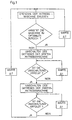
- a first step of the method according to the invention is provided current speed value of the electrical machine at periodic intervals ⁇ T to read into a memory area of the control unit.
- the characteristics stored in the control unit determine whether the Drive machine works in an optimal range in terms of efficiency.
- a query is made as to whether the switchover has taken place, this can be done, for example, that again the current speed value of the engine in periodic query time intervals ⁇ t is determined. Is the switchover has not yet taken place, the query is carried out again after ⁇ t. is on the other hand, the transmission of the first drive machine is switched, so the switching of the transmission of the second one follows Drive machine made.
- the performance of the second Drive machine is increased to the extent that the tractive force at the Switching the transmission of the first drive machine is reduced. This measure makes it possible to reduce the tractive force when shifting the transmission by the remaining drive machines and thus the failure of a drive unit during the switching process. A In such a case, traction reduction would not occur at all.
- the front axle can be a drive machine with gearbox and the rear axle must be assigned the same. Then it is possible first to switch the transmission of the front axle drive machine and then the gearbox of the rear axle or vice versa.
- each wheel of an axle has its own Drive machine with a downstream transmission is assigned. Then the following switching sequence options are available: First, this is the left front axle drive machine as seen in the direction of travel assigned gear and then that of the drive machine seen the right wheel in the direction of travel. Then the Switching process on the rear axle analogous to that of the front axle instead. Of course, it is possible to start with the gearbox of the rear axle switch and then that of the front axle. In one particularly preferred embodiment, a crossover is provided. The means that first the gear of a wheel of the front axle is switched is, for example, that seen on the left wheel in the direction of travel assigned, and then the gear of the right wheel of the Rear axle.
- Figure 1 are the respective wheels 5,6 of an axle that the May be front axle or rear axle, assigned drive machines 1, 2 and the downstream transmission 3, 4 shown.
- Both downstream gears are multi-stage, preferably two-stage gearboxes that are synchronized or unsynchronized can. It is particularly advantageous as a two-stage dog gear transmission (see for example Dubbel, paperback for mechanical engineering, 1996, pages G 63 to G 195) to be provided, which are characterized in particular by a distinguish simple gearbox design. Furthermore need such Gearbox only during the shift auxiliary energy, which the Loss of efficiency through the transmission itself is low.
- the respective drive unit from the drive machine, the present one Transversal Weg is, and gears are each assigned to a wheel. So is the transverse flux machine 1 and the downstream transmission 3 in Left wheel 5 seen in the direction of travel, and in an analogous manner the Transversalhnemaschine 2 and the transmission 4 in the direction of travel seen right wheel 6 assigned. Both the transverse flux motors 1, 2 as well as the gears 3, 4 are via control lines 7, 8, 9, 10 with a Control device 20, which preferably has a microcomputer corresponding outputs is connected.
- measuring lines 21, 22 are provided, which are also connected to the control device.
- the measuring lines 21, 22 become measuring signals which are Sensors are removed from the transverse flux machine to which Control device transmitted.
- sensors or sensors it can are in one embodiment speed sensors with which the current speed of the transverse flux machine is determined.
- control lines 7, 8, 9, 10 control signals to both the Transverse flux machine as well as the subordinate transmission.
- signals can be sent to one of the control lines 9, 10 Actuator are transmitted, which actuates the transmission, that is in switches the present case.
- Commercially available actuators are conceivable Solenoid valves, such as those used for transmission control.
- the on the transverse flux machine connected control lines 7, 8th make it possible to control them, for example the power output increase in the short term, as long as the gear of the other machine is toggled to comment on an interruption in traction.
Description
- Abbildung 1
- ein Ablaufdiagramm der Fahrsteuerung in einer einfachen Version ohne Kompensation der durch die Umschaltung verursachten Zugkraftreduktion
- Abbildung 2
- die erfindungsgemäße Steuereinrichtung zur Fahrsteuerung für ein Fahrzeug mit mehreren Antriebsmaschinen.
Claims (11)
- Verfahren zum Betrieb eines Fahrzeuges mit mehreren elektrischen Antriebsmaschinen (1,2), wobei jedem Rad einer Achse des Fahrzeuges eine elektrische Antriebsmaschine zugeordnet wird und jeder der Maschinen ein mindestens zweistufiges, schaltbares Getriebe (3,4) nachgeordnet ist, mit folgenden Merkmalen:1.1 eine Schaltung der nachgeordneten Getriebe (3,4) erfolgt in Abhängigkeit vom Gesamtwirkungsgrad der jeweiligen Antriebsmaschine (1,2) beim Erreichen vorbestimmter, vom Gesamtwirkungsgrad abhängiger Schaltpunkte;1.2 die den elektrischen Antriebsmaschinen (1,2) nachgeordneten Getriebe werden (3,4) zeitlich versetzt geschaltet, wobei der Schaltvorgang des einer ersten Antriebsmaschine nachgeordneten Getriebes überwacht wird und der Schaltvorgang eines einer zweiten Antriebsmaschine nachgeordneten Getriebes erst erfolgt, wenn der Schaltvorgang des ersten Getriebes abgeschlossen ist, derart, daß keine Zugkraftunterbrechung im Gesamtantriebssystem auftritt.
- Verfahren nach Anspruch 1, dadurch gekennzeichnet, daß die elektrische Maschine eine Transversalflußmaschine ist.
- Verfahren nach einem der Ansprüche 1 bis 2, dadurch gekennzeichnet, daß
zunächst das Getriebe der Antriebsmaschine des linken Rades in Fahrtrichtung gesehen der Vorder- bzw. Hinterachse geschaltet wird und anschließend das Getriebe der Antriebsmaschine des rechten Rades in Fahrtrichtung gesehen der Vorder- bzw. Hinterachse geschaltet wird, oder zunächst das Getriebe der Antriebsmaschine des rechten Rades in Fahrtrichtung gesehen der Vorder- bzw. Hinterachse geschaltet wird und anschließend das Getriebe der Antriebsmaschine des linken Rades in Fahrtrichtung gesehen der Vorder- bzw. Hinterachse geschaltet wird. - Verfahren nach einem der Ansprüche 1 bis 2, dadurch gekennzeichnet, daß zunächst das Getriebe der Antriebsmaschine des linken Rades in Fahrtrichtung gesehen der Vorderachse geschaltet wird, und anschließend das Getriebe der Antriebsmaschine des rechten Rades in Fahrtrichtung gesehen der Hinterachse oder zunächst das Getriebe der Antriebsmaschine des rechten Rades in Fahrtrichtung gesehen der Hinterachse geschaltet wird, und anschließend das Getriebe der Antriebsmaschine des linken Rades der Vorderachse geschaltet wird.
- Verfahren gemäß einem der Ansprüche 1 bis 4, dadurch gekennzeichnet, daß
beim Schalten zum Ausgleich der Zugkraftreduktion durch den Schaltvorgang die übrigen Antriebsmaschinen kurzzeitig höher belastet werden, derart, daß überhaupt keine Zugkraftreduktion auftritt. - Steuereinrichtung zur Fahrsteuerung für ein Fahrzeug mit
mehreren Antriebsmaschinen (1,2), wobei jedem Rad einer Achse des Fahrzeuges eine Antriebsmaschine zugeordnet ist;
den Antriebsmaschinen nachgeordneten mindestens zweistufigen Getrieben (3,4);
den Antriebsmaschinen zugeordneten Drehzahlaufnehmern zur Aufnahme der Drehzahl einer Antriebsmaschine;
einer Steuereinrichtung für die Antriebsmaschine und die nachgeordneten Getriebe,
wobei die Steuereinrichtung (20) an das der ersten Antriebsmaschine (1) nachgeschaltete Getriebe (3) über eine erste Schaltleitung (9) angeschlossen ist, derart, daß bei Erreichen des Schaltpunktes ein Schaltimpuls zum Schalten des Getriebes über die Schaltleitung zugeführt wird;
dadurch gekennzeichnet, daß
die Antriebsmaschinen (1,2) elektrische Antriebsmaschinen sind;
die Steuereinrichtung (20) einen Speicherbereich aufweist, in den die von dem Drehzahlaufnehmer aufgenommene Drehzahl der Antriebsmaschine eingelesen wird und anhand eines Kennlinienfeldes, das in der Steuereinrichtung abgelegt ist, der Gesamtwirkungsgrad der Antriebsmaschine bestimmt wird; und
die Steuereinrichtung (20) an das einer zweiten Antriebseinrichtung (2) nachgeschaltete Getriebe (4) über eine zweite Schaltleitung (10) anschlossen ist, derart, daß ein Schaltimpuls von der Steuereinrichtung zugeführt wird, nachdem das erste Getriebe umgeschaltet worden ist. - Steuereinrichtung gemäß Anspruch 6, dadurch gekennzeichnet, daß
die elektrische Maschine eine Transversalflußmaschine ist. - Steuereinrichtung gemäß einem der Ansprüche 6 bis 7, dadurch gekennzeichnet, daß
die den Antriebsmaschinen nachgeordneten Getriebe zweistufige Getriebe sind. - Steuereinrichtung nach einem der Ansprüche 6 bis 8, dadurch gekennzeichnet, daß
die Getriebe Klauengetriebe sind. - Steuereinrichtung gemäß einem der Ansprüche 6 bis 9, dadurch gekennzeichnet, daß
die Getriebe synchronisiert sind. - Steuereinrichtung gemäß einem der Ansprürhe 6 bis 10, dadurch gekennzeichnet, daß
die Getriebe unsynchronisiert sind.
Applications Claiming Priority (2)
| Application Number | Priority Date | Filing Date | Title |
|---|---|---|---|
| DE19619321A DE19619321C2 (de) | 1996-05-14 | 1996-05-14 | Verfahren zum Betrieb eines Fahrzeugs mit mehreren elektrischen Antriebsmaschinen |
| DE19619321 | 1996-05-14 |
Publications (3)
| Publication Number | Publication Date |
|---|---|
| EP0807772A2 EP0807772A2 (de) | 1997-11-19 |
| EP0807772A3 EP0807772A3 (de) | 1999-06-09 |
| EP0807772B1 true EP0807772B1 (de) | 2002-12-04 |
Family
ID=7794226
Family Applications (1)
| Application Number | Title | Priority Date | Filing Date |
|---|---|---|---|
| EP97107057A Expired - Lifetime EP0807772B1 (de) | 1996-05-14 | 1997-04-29 | Verfahren zum Betreiben eines Fahrzeugs mit mehreren Antriebsmaschinen |
Country Status (3)
| Country | Link |
|---|---|
| US (1) | US5879265A (de) |
| EP (1) | EP0807772B1 (de) |
| DE (2) | DE19619321C2 (de) |
Cited By (2)
| Publication number | Priority date | Publication date | Assignee | Title |
|---|---|---|---|---|
| US7076876B2 (en) | 2001-05-17 | 2006-07-18 | Michelin Recherche Et Technique S.A. | Machine for presenting a tire with the axis horizontal |
| DE102006014514A1 (de) * | 2006-03-24 | 2007-10-11 | Getrag Innovations Gmbh | Antriebsstrang und Herstell- und Einbauverfahren |
Families Citing this family (63)
| Publication number | Priority date | Publication date | Assignee | Title |
|---|---|---|---|---|
| DE19932118C1 (de) * | 1999-07-09 | 2000-10-26 | Daimler Chrysler Ag | Elektrischer Mehrfachmotorenantrieb für ein Kraftfahrzeug |
| US6757597B2 (en) * | 2001-01-31 | 2004-06-29 | Oshkosh Truck | A/C bus assembly for electronic traction vehicle |
| US7729831B2 (en) * | 1999-07-30 | 2010-06-01 | Oshkosh Corporation | Concrete placement vehicle control system and method |
| US6885920B2 (en) * | 1999-07-30 | 2005-04-26 | Oshkosh Truck Corporation | Control system and method for electric vehicle |
| US6447423B1 (en) | 2000-07-31 | 2002-09-10 | Caterpillar Inc. | Method and apparatus for adjusting transmission ratio commands for a continuously variable transmission |
| DE10057092A1 (de) | 2000-11-17 | 2002-05-23 | Zahnradfabrik Friedrichshafen | Antriebsanlage für ein Fahrzeug |
| US7379797B2 (en) * | 2001-01-31 | 2008-05-27 | Oshkosh Truck Corporation | System and method for braking in an electric vehicle |
| US7277782B2 (en) * | 2001-01-31 | 2007-10-02 | Oshkosh Truck Corporation | Control system and method for electric vehicle |
| JP3744414B2 (ja) * | 2001-11-29 | 2006-02-08 | トヨタ自動車株式会社 | 車両の制御装置 |
| US7254468B2 (en) * | 2001-12-21 | 2007-08-07 | Oshkosh Truck Corporation | Multi-network control system for a vehicle |
| US7302320B2 (en) | 2001-12-21 | 2007-11-27 | Oshkosh Truck Corporation | Failure mode operation for an electric vehicle |
| US7520354B2 (en) * | 2002-05-02 | 2009-04-21 | Oshkosh Truck Corporation | Hybrid vehicle with combustion engine/electric motor drive |
| FR2842147A1 (fr) * | 2002-07-15 | 2004-01-16 | Conception & Dev Michelin Sa | Chaine de traction comportant un mecanisme de changement de rapport integre dans une roue |
| US6909959B2 (en) * | 2003-03-07 | 2005-06-21 | Stephen James Hallowell | Torque distribution systems and methods for wheeled vehicles |
| DE10316862A1 (de) * | 2003-04-11 | 2004-10-21 | Deere & Company, Moline | Antriebssystem für Fahrzeuge |
| ATE372477T1 (de) * | 2003-07-09 | 2007-09-15 | Michelin Rech Tech | Verfahren zum gangwechsel eines antriebsstranges der für jedes antriebsrad einen schaltmechanismus besitzt |
| FR2857426A1 (fr) * | 2003-07-09 | 2005-01-14 | Conception & Dev Michelin Sa | Procede de changement de rapport pour chaine de traction comportant un mecanisme de changement de rapport pour chaque roue motrice |
| DE10347596B3 (de) * | 2003-10-14 | 2005-06-02 | Bayerische Motoren Werke Ag | Verfahren zur Optimierung des Gesamtwirkungsgrades des Antriebssystems eines Kraftfahrzeugs |
| US7439711B2 (en) * | 2004-09-27 | 2008-10-21 | Oshkosh Corporation | Energy storage device including a status indicator |
| US20060112781A1 (en) * | 2004-11-30 | 2006-06-01 | Brian Kuras | Multi-motor/multi-range torque transmitting power system |
| DE102005019489A1 (de) * | 2005-04-27 | 2006-11-09 | Krauss-Maffei Wegmann Gmbh & Co. Kg | Allradangetriebenes Kraftfahrzeug |
| DE102006006766A1 (de) * | 2006-02-13 | 2007-08-23 | Claas Selbstfahrende Erntemaschinen Gmbh | Motorfahrzeug |
| US20070251742A1 (en) * | 2006-05-01 | 2007-11-01 | Adams Herbert L Iii | Vehicle with hybrid power train providing part-time all-wheel drive |
| US7364524B2 (en) * | 2006-05-01 | 2008-04-29 | American Axel & Manufacturing, Inc. | Driveline coupling for electric module |
| US8139109B2 (en) * | 2006-06-19 | 2012-03-20 | Oshkosh Corporation | Vision system for an autonomous vehicle |
| US8947531B2 (en) | 2006-06-19 | 2015-02-03 | Oshkosh Corporation | Vehicle diagnostics based on information communicated between vehicles |
| DE102006058982B4 (de) * | 2006-12-14 | 2017-07-20 | Zf Friedrichshafen Ag | Verfahren zum Schalten von mindestens zwei automatisierten Schaltgetrieben |
| US7973446B2 (en) * | 2007-05-09 | 2011-07-05 | Motor Excellence, Llc | Electrical devices having tape wound core laminate rotor or stator elements |
| WO2010062765A2 (en) | 2008-11-03 | 2010-06-03 | Motor Excellence, Llc | Transverse and/or commutated flux system rotor concepts |
| WO2011115632A1 (en) * | 2010-03-15 | 2011-09-22 | Motor Excellence Llc | Transverse and/or commutated flux systems configured to provide reduced flux leakage, hysteresis loss reduction, and phase matching |
| CN102959832B (zh) * | 2010-03-15 | 2016-11-16 | 电扭矩机器股份有限公司 | 具有相偏移的横向和/或换向通量系统 |
| WO2011115633A1 (en) | 2010-03-15 | 2011-09-22 | Motor Excellence Llc | Transverse and/or commutated flux system for electric bicycles |
| US8337352B2 (en) | 2010-06-22 | 2012-12-25 | Oshkosh Corporation | Electromechanical variable transmission |
| WO2012067895A2 (en) | 2010-11-17 | 2012-05-24 | Motor Excellence, Llc | Transverse and/or commutated flux system coil concepts |
| WO2012067896A2 (en) | 2010-11-17 | 2012-05-24 | Motor Excellence, Llc | Transverse and/or commutated flux systems having laminated and powdered metal portions |
| EP2641316B1 (de) | 2010-11-17 | 2019-02-13 | Motor Excellence, LLC | Quer- oder mischflusssysteme mit segmentierten statorlamellen |
| DE102012209920A1 (de) * | 2012-06-13 | 2013-12-19 | Siemens Aktiengesellschaft | Fahrzeug und Verfahren zum Betreiben eines Fahrzeugs |
| US9132736B1 (en) | 2013-03-14 | 2015-09-15 | Oshkosh Defense, Llc | Methods, systems, and vehicles with electromechanical variable transmission |
| EP2905162B1 (de) * | 2014-02-07 | 2016-09-21 | Visedo Oy | Elektromechanischer Antrieb für eine Arbeitsmaschine |
| US9651120B2 (en) | 2015-02-17 | 2017-05-16 | Oshkosh Corporation | Multi-mode electromechanical variable transmission |
| US10421350B2 (en) | 2015-10-20 | 2019-09-24 | Oshkosh Corporation | Inline electromechanical variable transmission system |
| US10584775B2 (en) | 2015-02-17 | 2020-03-10 | Oshkosh Corporation | Inline electromechanical variable transmission system |
| US9650032B2 (en) | 2015-02-17 | 2017-05-16 | Oshkosh Corporation | Multi-mode electromechanical variable transmission |
| US10578195B2 (en) | 2015-02-17 | 2020-03-03 | Oshkosh Corporation | Inline electromechanical variable transmission system |
| US9656659B2 (en) | 2015-02-17 | 2017-05-23 | Oshkosh Corporation | Multi-mode electromechanical variable transmission |
| US10982736B2 (en) | 2015-02-17 | 2021-04-20 | Oshkosh Corporation | Multi-mode electromechanical variable transmission |
| US11701959B2 (en) | 2015-02-17 | 2023-07-18 | Oshkosh Corporation | Inline electromechanical variable transmission system |
| US9469199B1 (en) * | 2015-05-28 | 2016-10-18 | Atieva, Inc. | Dual data rate traction control system for a four wheel drive electric vehicle |
| US9463697B1 (en) * | 2015-05-28 | 2016-10-11 | Atieva, Inc. | Dual data rate traction control system for a two wheel drive electric vehicle |
| US10207751B2 (en) | 2016-05-09 | 2019-02-19 | Nikola Motor Company Llc | Motor gearbox assembly |
| US10981609B2 (en) | 2015-12-30 | 2021-04-20 | Nikola Corporation | Systems, methods, and devices for an automobile door or window |
| US11001129B2 (en) | 2015-12-30 | 2021-05-11 | Nikola Corporation | Cargo door for semi-truck |
| US10435075B2 (en) | 2016-05-06 | 2019-10-08 | Arvinmeritor Technology, Llc | Suspension module having a subframe assembly |
| US10266025B2 (en) | 2016-05-06 | 2019-04-23 | Arvinmeritor Technology, Llc | Suspension module having an air spring pedestal |
| CN109996978B (zh) | 2016-11-25 | 2021-05-04 | 沃尔沃卡车集团 | 用于车辆的驱动装置 |
| US10272899B2 (en) | 2017-08-01 | 2019-04-30 | Proterra Inc. | Controlling the powertrain of a vehicle |
| DE102017219756A1 (de) * | 2017-11-07 | 2019-05-09 | Robert Bosch Gmbh | Fahrantriebsanordnung für eine Arbeitsmaschine |
| US10926596B2 (en) | 2019-02-28 | 2021-02-23 | Arvinmeritor Technology, Llc | Suspension system |
| US10913321B2 (en) | 2019-03-04 | 2021-02-09 | Arvinmeritor Technology, Llc | Suspension system |
| US10814917B2 (en) | 2019-03-04 | 2020-10-27 | Arvinmeritor Technology, Llc | Assembly having a skid plate module |
| DE102019214986A1 (de) | 2019-09-30 | 2021-04-01 | Zf Friedrichshafen Ag | Antriebsachse eines Elektrofahrzeuges und Lastschaltverfahren |
| DE102019216562A1 (de) * | 2019-10-28 | 2021-04-29 | Zf Friedrichshafen Ag | Antriebsanordnung eines Elektrofahrzeuges und Lastschaltverfahren |
| FI20225708A1 (fi) * | 2022-08-09 | 2024-02-10 | Ponsse Oyj | Työkone ja menetelmä työkoneen voimansiirrossa |
Family Cites Families (9)
| Publication number | Priority date | Publication date | Assignee | Title |
|---|---|---|---|---|
| DE1655194C3 (de) * | 1967-12-07 | 1979-04-26 | Robert Bosch Gmbh, 7000 Stuttgart | Selbsttätige Schalteinrichtung für Kraftfahrzeuge mit mindestens zwei voneinander unabhängigen Antriebsgruppen |
| JPS5266224A (en) * | 1975-11-29 | 1977-06-01 | Agency Of Ind Science & Technol | Automatic transmission control device for elecric car |
| JPS52155717A (en) * | 1976-06-18 | 1977-12-24 | Agency Of Ind Science & Technol | Automatic transmission system for electric vehicle |
| US4766967A (en) * | 1985-12-27 | 1988-08-30 | Eaton Corporation | Oscillation control system for electric motor drive |
| DE3705089A1 (de) * | 1987-02-13 | 1988-08-25 | Weh Herbert | Transversalflussmaschine in sammleranordnung |
| DE3927453A1 (de) | 1989-08-19 | 1991-02-21 | Weh Herbert | Permanenterregte transversalfluss-(tf-)maschine mit hochwirksamen magnetkreisen |
| JPH05161216A (ja) * | 1991-12-05 | 1993-06-25 | Honda Motor Co Ltd | 電動車両の変速制御装置 |
| JP3200901B2 (ja) * | 1991-12-20 | 2001-08-20 | 株式会社日立製作所 | 電気自動車の駆動装置 |
| JP3441162B2 (ja) * | 1994-05-27 | 2003-08-25 | 本田技研工業株式会社 | 電動車両の変速制御方法 |
-
1996
- 1996-05-14 DE DE19619321A patent/DE19619321C2/de not_active Expired - Fee Related
-
1997
- 1997-04-29 EP EP97107057A patent/EP0807772B1/de not_active Expired - Lifetime
- 1997-04-29 DE DE59708862T patent/DE59708862D1/de not_active Expired - Lifetime
- 1997-05-14 US US08/856,107 patent/US5879265A/en not_active Expired - Fee Related
Cited By (2)
| Publication number | Priority date | Publication date | Assignee | Title |
|---|---|---|---|---|
| US7076876B2 (en) | 2001-05-17 | 2006-07-18 | Michelin Recherche Et Technique S.A. | Machine for presenting a tire with the axis horizontal |
| DE102006014514A1 (de) * | 2006-03-24 | 2007-10-11 | Getrag Innovations Gmbh | Antriebsstrang und Herstell- und Einbauverfahren |
Also Published As
| Publication number | Publication date |
|---|---|
| DE19619321C2 (de) | 1998-07-09 |
| DE19619321A1 (de) | 1997-11-20 |
| DE59708862D1 (de) | 2003-01-16 |
| EP0807772A2 (de) | 1997-11-19 |
| US5879265A (en) | 1999-03-09 |
| EP0807772A3 (de) | 1999-06-09 |
Similar Documents
| Publication | Publication Date | Title |
|---|---|---|
| EP0807772B1 (de) | Verfahren zum Betreiben eines Fahrzeugs mit mehreren Antriebsmaschinen | |
| DE19816450B4 (de) | Antriebseinheit für ein Hybridfahrzeug | |
| EP2323862B1 (de) | Verfahren und vorrichtung zum betreiben eines hybridantriebes für ein fahrzeug | |
| DE19954544B4 (de) | Kraftfahrzeugantrieb | |
| DE19955312B4 (de) | Antriebssystem für Flurförderzeuge | |
| EP2738030A2 (de) | Zugkraftunterstütztes Mehrgruppengetriebe und Verfahren zu dessen Betreiben | |
| EP0348622B1 (de) | Stufenwechselgetriebe | |
| DE19919454C2 (de) | Fahrzeugantriebseinrichtung | |
| DE102019218239A1 (de) | Antriebseinheit für eine elektrisch angetriebene Achse und Verfahren zum Betreiben der Antriebseinheit | |
| DE102013200646A1 (de) | Verfahren zum Schalten eines in Gruppenbauweise ausgeführten Kraftfahrzeug-getriebes, sowie Kraftfahrzeuggetriebe in Gruppenbauweise | |
| DE19955313C2 (de) | Antriebssystem für Flurförderzeuge | |
| EP0796758B1 (de) | Antriebseinheit für ein Fahrzeug, insbesondere für Stadtbusse | |
| DE19800880A1 (de) | Schaltvorrichtung für ein mehrgängiges Wechselgetriebe | |
| EP3854616A1 (de) | Getriebe mit nebenabtrieb | |
| DE3421387C2 (de) | ||
| DE602004005350T2 (de) | Zwei planetengetriebe umfassendes, stufenlos verstellbares leistungsverzweigungsgetriebe mit zwei betriebsmoden | |
| DE102020101667A1 (de) | Antriebsstrang für ein Kraftfahrzeug | |
| DE102016200562A1 (de) | Mechanischer gangschaltvorgang mit automatisierter kupplung | |
| DE102019202974A1 (de) | Getriebeanordnung, Kraftfahrzeugantriebsstrang und Verfahren zu dessen Betreiben | |
| DE102018120026A1 (de) | Verfahren zum Betreiben eines Kraftfahrzeugs mit elektrischem Antrieb | |
| DE102005036894A1 (de) | Antriebsstrang mit Parallelschaltgetriebe | |
| DE102013010013A1 (de) | Verfahren und Vorrichtung zur Steuerung eines Schaltgetriebes | |
| EP1434701B1 (de) | Mit einer brennkraftmaschine gekoppelte elektrische maschine in einem kraftfahrzeug | |
| DE102006058982B4 (de) | Verfahren zum Schalten von mindestens zwei automatisierten Schaltgetrieben | |
| DE102020000462A1 (de) | Modularer Getriebebaukasten für ein Kraftfahrzeug |
Legal Events
| Date | Code | Title | Description |
|---|---|---|---|
| PUAI | Public reference made under article 153(3) epc to a published international application that has entered the european phase |
Free format text: ORIGINAL CODE: 0009012 |
|
| AK | Designated contracting states |
Kind code of ref document: A2 Designated state(s): DE FR GB IT SE |
|
| PUAL | Search report despatched |
Free format text: ORIGINAL CODE: 0009013 |
|
| AK | Designated contracting states |
Kind code of ref document: A3 Designated state(s): DE FR GB IT SE |
|
| 17P | Request for examination filed |
Effective date: 19990518 |
|
| GRAG | Despatch of communication of intention to grant |
Free format text: ORIGINAL CODE: EPIDOS AGRA |
|
| GRAG | Despatch of communication of intention to grant |
Free format text: ORIGINAL CODE: EPIDOS AGRA |
|
| GRAH | Despatch of communication of intention to grant a patent |
Free format text: ORIGINAL CODE: EPIDOS IGRA |
|
| 17Q | First examination report despatched |
Effective date: 20020605 |
|
| GRAH | Despatch of communication of intention to grant a patent |
Free format text: ORIGINAL CODE: EPIDOS IGRA |
|
| GRAA | (expected) grant |
Free format text: ORIGINAL CODE: 0009210 |
|
| AK | Designated contracting states |
Kind code of ref document: B1 Designated state(s): DE FR GB IT SE |
|
| REG | Reference to a national code |
Ref country code: GB Ref legal event code: FG4D Free format text: NOT ENGLISH |
|
| GBT | Gb: translation of ep patent filed (gb section 77(6)(a)/1977) |
Effective date: 20021204 |
|
| REF | Corresponds to: |
Ref document number: 59708862 Country of ref document: DE Date of ref document: 20030116 |
|
| ET | Fr: translation filed | ||
| PLBE | No opposition filed within time limit |
Free format text: ORIGINAL CODE: 0009261 |
|
| STAA | Information on the status of an ep patent application or granted ep patent |
Free format text: STATUS: NO OPPOSITION FILED WITHIN TIME LIMIT |
|
| 26N | No opposition filed |
Effective date: 20030905 |
|
| PGFP | Annual fee paid to national office [announced via postgrant information from national office to epo] |
Ref country code: SE Payment date: 20070416 Year of fee payment: 11 |
|
| PGFP | Annual fee paid to national office [announced via postgrant information from national office to epo] |
Ref country code: GB Payment date: 20070411 Year of fee payment: 11 |
|
| PGFP | Annual fee paid to national office [announced via postgrant information from national office to epo] |
Ref country code: IT Payment date: 20070627 Year of fee payment: 11 |
|
| PGFP | Annual fee paid to national office [announced via postgrant information from national office to epo] |
Ref country code: FR Payment date: 20070413 Year of fee payment: 11 |
|
| EUG | Se: european patent has lapsed | ||
| GBPC | Gb: european patent ceased through non-payment of renewal fee |
Effective date: 20080429 |
|
| REG | Reference to a national code |
Ref country code: FR Ref legal event code: ST Effective date: 20081231 |
|
| PG25 | Lapsed in a contracting state [announced via postgrant information from national office to epo] |
Ref country code: FR Free format text: LAPSE BECAUSE OF NON-PAYMENT OF DUE FEES Effective date: 20080430 |
|
| PG25 | Lapsed in a contracting state [announced via postgrant information from national office to epo] |
Ref country code: GB Free format text: LAPSE BECAUSE OF NON-PAYMENT OF DUE FEES Effective date: 20080429 |
|
| PG25 | Lapsed in a contracting state [announced via postgrant information from national office to epo] |
Ref country code: IT Free format text: LAPSE BECAUSE OF NON-PAYMENT OF DUE FEES Effective date: 20080429 |
|
| PG25 | Lapsed in a contracting state [announced via postgrant information from national office to epo] |
Ref country code: SE Free format text: LAPSE BECAUSE OF NON-PAYMENT OF DUE FEES Effective date: 20080430 |
|
| PGFP | Annual fee paid to national office [announced via postgrant information from national office to epo] |
Ref country code: DE Payment date: 20120509 Year of fee payment: 16 |
|
| PG25 | Lapsed in a contracting state [announced via postgrant information from national office to epo] |
Ref country code: DE Free format text: LAPSE BECAUSE OF NON-PAYMENT OF DUE FEES Effective date: 20131101 |
|
| REG | Reference to a national code |
Ref country code: DE Ref legal event code: R119 Ref document number: 59708862 Country of ref document: DE Effective date: 20131101 |