EP0803736A2 - MR apparatus with cylindrical coil means and with surface coil means - Google Patents
MR apparatus with cylindrical coil means and with surface coil means Download PDFInfo
- Publication number
- EP0803736A2 EP0803736A2 EP97201103A EP97201103A EP0803736A2 EP 0803736 A2 EP0803736 A2 EP 0803736A2 EP 97201103 A EP97201103 A EP 97201103A EP 97201103 A EP97201103 A EP 97201103A EP 0803736 A2 EP0803736 A2 EP 0803736A2
- Authority
- EP
- European Patent Office
- Prior art keywords
- arrangement
- coil arrangement
- coil
- solenoid
- overlap
- Prior art date
- Legal status (The legal status is an assumption and is not a legal conclusion. Google has not performed a legal analysis and makes no representation as to the accuracy of the status listed.)
- Granted
Links
Images
Classifications
-
- G—PHYSICS
- G01—MEASURING; TESTING
- G01R—MEASURING ELECTRIC VARIABLES; MEASURING MAGNETIC VARIABLES
- G01R33/00—Arrangements or instruments for measuring magnetic variables
- G01R33/20—Arrangements or instruments for measuring magnetic variables involving magnetic resonance
- G01R33/28—Details of apparatus provided for in groups G01R33/44 - G01R33/64
- G01R33/32—Excitation or detection systems, e.g. using radio frequency signals
- G01R33/36—Electrical details, e.g. matching or coupling of the coil to the receiver
- G01R33/3642—Mutual coupling or decoupling of multiple coils, e.g. decoupling of a receive coil from a transmission coil, or intentional coupling of RF coils, e.g. for RF magnetic field amplification
- G01R33/365—Decoupling of multiple RF coils wherein the multiple RF coils have the same function in MR, e.g. decoupling of a receive coil from another receive coil in a receive coil array, decoupling of a transmission coil from another transmission coil in a transmission coil array
-
- G—PHYSICS
- G01—MEASURING; TESTING
- G01R—MEASURING ELECTRIC VARIABLES; MEASURING MAGNETIC VARIABLES
- G01R33/00—Arrangements or instruments for measuring magnetic variables
- G01R33/20—Arrangements or instruments for measuring magnetic variables involving magnetic resonance
- G01R33/28—Details of apparatus provided for in groups G01R33/44 - G01R33/64
- G01R33/32—Excitation or detection systems, e.g. using radio frequency signals
- G01R33/34—Constructional details, e.g. resonators, specially adapted to MR
- G01R33/341—Constructional details, e.g. resonators, specially adapted to MR comprising surface coils
- G01R33/3415—Constructional details, e.g. resonators, specially adapted to MR comprising surface coils comprising arrays of sub-coils, i.e. phased-array coils with flexible receiver channels
-
- G—PHYSICS
- G01—MEASURING; TESTING
- G01R—MEASURING ELECTRIC VARIABLES; MEASURING MAGNETIC VARIABLES
- G01R33/00—Arrangements or instruments for measuring magnetic variables
- G01R33/20—Arrangements or instruments for measuring magnetic variables involving magnetic resonance
- G01R33/28—Details of apparatus provided for in groups G01R33/44 - G01R33/64
- G01R33/32—Excitation or detection systems, e.g. using radio frequency signals
- G01R33/34—Constructional details, e.g. resonators, specially adapted to MR
- G01R33/34046—Volume type coils, e.g. bird-cage coils; Quadrature bird-cage coils; Circularly polarised coils
-
- G—PHYSICS
- G01—MEASURING; TESTING
- G01R—MEASURING ELECTRIC VARIABLES; MEASURING MAGNETIC VARIABLES
- G01R33/00—Arrangements or instruments for measuring magnetic variables
- G01R33/20—Arrangements or instruments for measuring magnetic variables involving magnetic resonance
- G01R33/28—Details of apparatus provided for in groups G01R33/44 - G01R33/64
- G01R33/32—Excitation or detection systems, e.g. using radio frequency signals
- G01R33/34—Constructional details, e.g. resonators, specially adapted to MR
- G01R33/341—Constructional details, e.g. resonators, specially adapted to MR comprising surface coils
Definitions
- the invention relates to an MR device for receiving MR signals from an examination area penetrated by a stationary homogeneous magnetic field and superimposed gradient magnetic fields after excitation by a high-frequency magnetic field by means of an MR coil arrangement which has a solenoid arrangement and a surface coil arrangement.
- Such a magnetic resonance (MR) device is known from EP-A 616 229.
- MR signals from several areas of a patient's body are received simultaneously with the aid of several coil arrangements.
- the cylindrical coil arrangement is, for example, a birdcage resonator designed for examining the head
- the surface coil arrangement is, for example, a quadrature coil arrangement which is arranged on the patient's chest.
- MR images of a patient's head and chest area can be created.
- Cylinder coil arrangement is generally understood to mean a coil arrangement which is cylindrical in shape and encloses one or more parts of the patient's body during an MR examination.
- the solenoid arrangement has an essentially homogeneous sensitivity, usually only one channel being required to receive the MR signals measured by the solenoid arrangement.
- surface coil arrangement or surface coils comprised by it are meant coils that are arranged on or near the surface of the body of a patient, but do not enclose the body or body parts. Such surface coils have a locally increased signal / noise ratio, but also have a clearly inhomogeneous one Sensitivity. Usually one or two surface coils of this type require their own reception channel.
- the present invention has for its object to further improve an MR device of the type mentioned.
- the two coil arrangements can be largely decoupled from one another by overlapping the two coil arrangements. Furthermore, it was found that the size of the overlap area has a great influence on the strength of the coupling. For this reason, means are provided according to the invention with which the size of the overlap area can be varied before or during the examination. Before the examination, for example, a phantom body (e.g. a container filled with water) could be arranged in the examination area and the overlap area changed until the best signal / noise ratio is achieved. This could also be done at the beginning of the examination of a patient, which has the advantage that his body anatomy is immediately taken into account when setting the best signal / noise ratio.
- a phantom body e.g. a container filled with water
- the MR device With the MR device according to the invention, it is possible to obtain a coherent MR image of a relatively large area, only a small number of reception channels being required, in contrast to an arrangement with a large number of surface coils covering an equally large area, which is essential for this more reception channels would be required. There is also one Sufficient homogeneity and a sufficiently large signal-to-noise ratio are guaranteed since couplings between the coil arrangements are largely suppressed by the invention.
- Another advantage of the invention is that conventional coil arrangements can be used for both the solenoid and surface coil arrangements, with only minor design changes having to be made.
- the solenoid arrangement has at least one birdcage resonator, a saddle coil arrangement, a solenoid coil arrangement or a loop array coil arrangement.
- a birdcage resonator is known from the above-mentioned EP-A 616 229
- a loop array coil arrangement consisting of a plurality of inductively coupled loops is known from US Pat. No. 50 03 265.
- a saddle coil arrangement consists, for example, of two individual so-called saddle coils, which are designed as loops and each cover half the circumference of a body or a body part on opposite sides.
- a solenoid coil arrangement is a coil arrangement in the form of a spiral.
- the surface coil arrangement has at least one surface coil which is at least partially adapted to the body surface of a patient.
- Such surface coils have a particularly good signal / noise ratio in the area of the body that they cover.
- adjacent surface coils are also overlapped in order to reduce the mutual coupling. Means for changing the size of the overlap area can also be provided.
- the solenoid arrangement is designed such that it can enclose the head of a patient at a short distance
- the surface coil arrangement is designed such that it can be adapted to the chest and / or neck area of a patient.
- MR images e.g. Sagittal or coronal sectional images can be created from the top of the head to the heart.
- a practical version has a field-of-view with a length of about 45 cm.
- a further embodiment of the invention provides that the means for adjusting the size of the overlap area comprise a rail device which enables the surface coil arrangement to be displaced with respect to the cylinder coil arrangement.
- a rail device which enables the surface coil arrangement to be displaced with respect to the cylinder coil arrangement.
- a displacement lock can also be provided, with which a variation of the overlap area is prevented after the optimal size of the overlap area has been found. This can be a locking screw or a mechanical lock, for example.
- the size of the surface coils included in the surface coil arrangement can be changed. It was found that the wider the side of a surface coil adjacent to the solenoid arrangement, the smaller the overlap area. Conversely, an optimization of the signal / noise ratio could thus be achieved in a once overlapping area was fixed by varying the size, in particular the width, of a surface coil. It would also be conceivable for both the size of the overlap area and the size to vary the surface coil. By varying the size of the surface coil, the field-of-view of the surface coil could also be adapted to the requirements of the desired image or the anatomy of the patient during or immediately before the examination.
- an MR coil arrangement comprising a solenoid arrangement and a surface coil arrangement, which is characterized in that the solenoid arrangement and the surface coil arrangement overlap in an overlap area and that the MR coil arrangement has means for adjusting the size of the overlap area.
- the MR device shown in FIG. 1 contains a high-frequency coil arrangement 1 with a hollow cylindrical cross-section, which generates a high-frequency magnetic field that is perpendicular to the plane of the drawing and penetrates the examination area in which a patient 2 is located, whose longitudinal body axis runs perpendicular to the plane of the drawing.
- the MR device also has a main field magnet (not shown in more detail) which generates a stationary, homogeneous magnetic field running perpendicular to the plane of the drawing.
- the MR device also has gradient coils, not shown in more detail, which likewise generate magnetic fields running perpendicular to the plane of the drawing, but with a gradient in one of three mutually perpendicular Directions.
- a control unit 3 controls the generation of the fields described above. In particular, it controls an oscillator 4, which is connected to the high-frequency coil arrangement 1, by means of which the high-frequency excitation takes place in the transmission mode. Furthermore, the control unit 3 controls a radio-frequency receiver 5, which is connected to various receiving coils and amplifies, demodulates and digitizes the received nuclear magnetic resonance signals. The signals are then processed in the processing unit 6.
- a cylindrical coil arrangement 7, which encloses part of the body of the patient 2 in a cylindrical manner, and a surface coil arrangement 8, which covers part of the body surface of the patient, are shown here as reception coils.
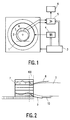
- FIG. 2 shows an embodiment of the invention for creating coherent MR images from the head and chest area of a patient 2.
- the solenoid arrangement here is a known birdcage resonator 7, which encloses the entire head of a patient 2 up to the neck.
- a birdcage resonator 7 can be used to generate MR images of the head, a single receiving channel having to be provided in the receiver.
- a first surface coil 8 is arranged on the body surface, which is adapted to the body surface, particularly in the neck area.
- the surface coil 8 and the birdcage resonator 7 overlap in an overlap region 100, that is to say the surface coil 8 partially projects into the space enclosed by the birdcage 7.
- a further surface coil 9 adapted to the body surface is arranged in the neck and shoulder region of the patient 2. This is also overlapped by the birdcage resonator 7, ie it also partially projects into the interior thereof.
- a further surface coil 10 is arranged in the back area of the patient 2 and is partially overlapped with the surface coil 9. A total of four reception channels are required for the MR device shown.
- the surface coils 8, 9, 10 are each constructed from a single wire loop.
- the proportion of the surface of the surface coils 8 and 9 that overlaps the birdcage resonator 7 is in practice about 10 to 20% of the total surface of the surface coils 8.9.
- the width of the overlap area is in the range of a few cm. However, the size of the overlap area also depends on the type, design and size of the coils and on the anatomy of the patient.
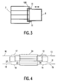
- FIG. 3 A top view of part of the embodiment shown in FIG. 2 is shown in FIG. 3.
- the overlap region 100 of the birdcage resonator 7 and the surface coil 8 can be seen.
- 11 denotes a rail device attached to both sides of the surface coil 8, which slides in a rail (not shown) attached to the birdcage resonator 7.
- the surface coil 8 can be displaced in the direction indicated by the double arrow with respect to the birdcage resonator 7, as a result of which the size of the overlap region 100 changes.
- FIG. 4 shows an alternative embodiment of an MR device according to the invention.
- This includes a birdcage resonator 24 and a large number of surface coils 12 to 23.
- the surface coils 12, 14, 17, 19, 20, 22 adjacent to the birdcage resonator 24 also overlap here with the birdcage resonator 24.
- the further surface coils 13 , 15, 16, 18, 21, 23 each overlap with the adjacent surface coil.
- the embodiment shown is suitable, for example, for creating MR images of an entire leg of a patient.
- the birdcage resonator 24 is arranged, for example, around the knee, the surface coils are distributed over the upper or lower leg.
- the signals received from two surface coils can also be received and processed after processing with a combination circuit on one channel are processed, so that seven reception channels are required for this arrangement.
- any other embodiment is conceivable.
- a further birdcage resonator or a saddle coil arrangement which surrounds the patient's foot can be provided in the end region.
- Two or more solenoid assemblies that partially overlap each other are also conceivable.
- quadrature coils or butterfly coils can also be used as surface coils.
- the surface coil arrangement can also consist of a combination of several different surface coils, with several surface coils, for example a loop and a butterfly coil, being arranged one above the other and covering approximately the same area of the body surface.
- the design of the solenoid arrangement can also differ from the embodiments shown.
- the birdcage can, for example, also have an elliptical cross section and / or have a conductive end surface and / or shoulder openings.
- a further additional decoupling between the surface coil and the solenoid arrangement can take place through a capacitive network between the two coil arrangements if a sufficient improvement in the decoupling is not possible, for example for design reasons, by changing the size of the overlap area.
Abstract
Description
Die Erfindung betrifft ein MR-Gerät zum Empfangen von MR-Signalen aus einem von einem stationären homogenen Magnetfeld und überlagerten Gradienten-Magnetfeldern durchsetzten Untersuchungsbereich nach Anregung durch ein hochfrequentes Magnetfeld mittels einer MR-Spulenanordnung, welche eine Zylinderspulenanordnung und eine Oberflächenspulenanordnung aufweist.The invention relates to an MR device for receiving MR signals from an examination area penetrated by a stationary homogeneous magnetic field and superimposed gradient magnetic fields after excitation by a high-frequency magnetic field by means of an MR coil arrangement which has a solenoid arrangement and a surface coil arrangement.
Ein derartiges Magnetresonanz (MR)-Gerät ist aus der EP-A 616 229 bekannt. Dort werden gleichzeitig MR-Signale aus mehreren Bereichen des Körpers eines Patienten mit Hilfe mehrerer Spulenanordnungen empfangen. Die Zylinderspulenanordnung ist dabei beispielsweise ein zur Untersuchung des Kopfes ausgestalteter Birdcage-Resonator, die Oberflächenspulenanordnung ist beispielsweise eine Quadraturspulenanordnung, die auf der Brust des Patienten angeordnet ist. Während einer Untersuchung können damit MR-Bilder vom Kopf- und vom Brustbereich eines Patienten erstellt werden.Such a magnetic resonance (MR) device is known from EP-A 616 229. There, MR signals from several areas of a patient's body are received simultaneously with the aid of several coil arrangements. The cylindrical coil arrangement is, for example, a birdcage resonator designed for examining the head, the surface coil arrangement is, for example, a quadrature coil arrangement which is arranged on the patient's chest. During an examination, MR images of a patient's head and chest area can be created.
Mit Zylinderspulenanordnung ist allgemein eine Spulenanordnung gemeint, die zylinderförmig ausgestaltet ist und bei einer MR-Untersuchung einen oder mehrere Körperteile des Patienten umschließt. Im umschlossenen Bereich weist die Zylinderspulenanordnung eine im wesentlichen homogene Empfindlichkeit auf, wobei meist nur ein Kanal zum Empfang der von der Zylinderspulenanordnung gemessenen MR-Signale erforderlich ist. Mit Oberflächenspulenanordnung bzw. davon umfaßten Oberflächenspulen sind Spulen gemeint, die auf oder in der Nähe der Oberfläche des Körpers eines Patienten angeordnet werden, den Körper oder Körperteile aber nicht umschließen. Derartige Oberflächenspulen weisen ein lokal erhöhtes Signal/Rauschverhältnis auf, haben jedoch auch eine deutlich inhomogene Empfindlichkeit. Meist erfordern eine oder zwei derartige Oberflächenspulen gemeinsam einen eigenen Empfangskanal.Cylinder coil arrangement is generally understood to mean a coil arrangement which is cylindrical in shape and encloses one or more parts of the patient's body during an MR examination. In the enclosed area, the solenoid arrangement has an essentially homogeneous sensitivity, usually only one channel being required to receive the MR signals measured by the solenoid arrangement. By surface coil arrangement or surface coils comprised by it are meant coils that are arranged on or near the surface of the body of a patient, but do not enclose the body or body parts. Such surface coils have a locally increased signal / noise ratio, but also have a clearly inhomogeneous one Sensitivity. Usually one or two surface coils of this type require their own reception channel.
Der vorliegenden Erfindung liegt die Aufgabe zugrunde, ein MR-Gerät der eingangs genannten Art weiter zu verbessern.The present invention has for its object to further improve an MR device of the type mentioned.
Diese Aufgabe wird erfindungegemäß dadurch gelöst, daß sich die Zylinderspulenanordnung und die Oberflächenspulenanordnung in einem Überlappungsbereich überlappen und daß das MR-Gerät Mittel zur Einstellung der Größe des Überlappungsbereichs aufweist.This object is achieved according to the invention in that the solenoid arrangement and the surface coil arrangement overlap in an overlap area and in that the MR device has means for adjusting the size of the overlap area.
Es wurde festgestellt, daß eine weitgehende Entkopplung der beiden Spulenanordnungen voneinander dadurch erreicht werden kann, daß sich die beiden Spulenanordnungen überlappen. Weiterhin wurde festgestellt, daß die Größe des Überlappungsbereichs einen großen Einfluß auf die Stärke der Kopplung hat. Deswegen sind erfindungsgemäß Mittel vorgesehen, mit denen die Größe des Überlappungsbereichs vor oder während der Untersuchung variiert werden kann. Vor der Untersuchung könnte dabei beispielsweise ein Phantomkörper (z.B. ein mit Wasser gefülltes Behältnis) im Untersuchungsbereich angeordnet und der Überlappungsbereich solange verändert werden, bis das beste Signal/Rauschverhältnis erzielt wird. Dies könnte auch zu Beginn der Untersuchung eines Patienten erfolgen, was den Vorteil hat, daß dessen Körperanatomie bei der Einstellung des besten Signal/Rauschverhältnisses unmittelbar Berücksichtigung findet.It has been found that the two coil arrangements can be largely decoupled from one another by overlapping the two coil arrangements. Furthermore, it was found that the size of the overlap area has a great influence on the strength of the coupling. For this reason, means are provided according to the invention with which the size of the overlap area can be varied before or during the examination. Before the examination, for example, a phantom body (e.g. a container filled with water) could be arranged in the examination area and the overlap area changed until the best signal / noise ratio is achieved. This could also be done at the beginning of the examination of a patient, which has the advantage that his body anatomy is immediately taken into account when setting the best signal / noise ratio.
Mit dem erfindungsgemäßen MR-Gerät ist es möglich, ein zusammenhängendes MR-Bild eines verhältnismäßig großen Bereichs zu erhalten, wobei nur eine geringe Anzahl von Empfangskanälen erforderlich ist, im Gegensatz zu einer Anordnung mit einer Vielzahl von eine gleich großen Bereich abdeckenden Oberflächenspulen, wofür wesentlich mehr Empfangskanäle erforderlich wären. Dabei ist auch eine ausreichende Homogenität und ein genügend großer Signal/Rauschabstand gewährleistet, da Kopplungen zwischen den Spulenanordnungen durch die Erfindung weitestgehend unterdrückt werden. Ein weiterer Vorteil der Erfindung liegt darin, daß sowohl für die Zylinderspulen- als auch für die Oberflächenspulenanordnung herkömmliche Spulenanordnungen verwendet werden können, wobei lediglich geringfügige konstruktive Veränderungen vorgenommen werden müssen.With the MR device according to the invention, it is possible to obtain a coherent MR image of a relatively large area, only a small number of reception channels being required, in contrast to an arrangement with a large number of surface coils covering an equally large area, which is essential for this more reception channels would be required. There is also one Sufficient homogeneity and a sufficiently large signal-to-noise ratio are guaranteed since couplings between the coil arrangements are largely suppressed by the invention. Another advantage of the invention is that conventional coil arrangements can be used for both the solenoid and surface coil arrangements, with only minor design changes having to be made.
In einer Weiterbildung der Erfindung ist vorgesehen, daß die Zylinderspulenanordnung mindestens einen Birdcage-Resonator, eine Sattelspulenanordnung, eine Solenoidspulenanordnung oder eine Loop-Array-Spulenanordnung aufweist. Ein Birdcage-Resonator ist aus der eingangs genannten EP-A 616 229 bekannt, eine aus mehreren induktiv gekoppelten Schleifen bestehende Loop-Array-Spulenanordnung ist aus der US-PS 50 03 265 bekannt. Eine Sattelspulenanordnung besteht beispielsweise aus zwei einzelnen sogenannten Sattelspulen, die als Schleifen ausgestaltet sind und auf gegenüberliegenden Seiten jeweils die Hälfte des Umfanges eines Körpers oder eines Körperteils überdecken. Eine Solenoidspulenanordnung ist eine in Form einer Spirale ausgebildete Spulenanordnung.In a further development of the invention it is provided that the solenoid arrangement has at least one birdcage resonator, a saddle coil arrangement, a solenoid coil arrangement or a loop array coil arrangement. A birdcage resonator is known from the above-mentioned EP-A 616 229, a loop array coil arrangement consisting of a plurality of inductively coupled loops is known from US Pat. No. 50 03 265. A saddle coil arrangement consists, for example, of two individual so-called saddle coils, which are designed as loops and each cover half the circumference of a body or a body part on opposite sides. A solenoid coil arrangement is a coil arrangement in the form of a spiral.
In einer weiteren Ausgestaltung der Erfindung ist vorgesehen, daß die Oberflächenspulenanordnung mindestens eine der Körperoberfläche eines Patienten zumindest bereichsweise angepaßte Oberflächenspule aufweist. Derartige Oberflächenspulen weisen ein besonders gutes Signal/Rauschverhältnis in dem Körperbereich auf, den sie bedecken. Bei einer mehrere Oberflächenspulen umfassenden Oberflächenspulenanordnung sind benachbarte Oberflächenspulen ebenfalls zur Verminderung der gegenseitigen Kopplung überlappt. Auch dabei können Mittel zur Veränderung der Größe des Überlappungsbereichs vorgesehen sein.In a further embodiment of the invention it is provided that the surface coil arrangement has at least one surface coil which is at least partially adapted to the body surface of a patient. Such surface coils have a particularly good signal / noise ratio in the area of the body that they cover. In the case of a surface coil arrangement comprising a plurality of surface coils, adjacent surface coils are also overlapped in order to reduce the mutual coupling. Means for changing the size of the overlap area can also be provided.
Eine bevorzugte Weiterbildung der Erfindung sieht vor, daß die Zylinderspulenanordnung derart ausgestaltet ist, daß sie den Kopf eines Patienten in geringem Abstand umschließen kann, und daß die Oberflächenspulenanordnung derart ausgestaltet ist, daß sie dem Brust- und/oder Nackenbereich eines Patienten angepaßbar ist. Damit können MR-Bilder, z.B. sagitale oder koronale Schnittbilder von der Kopfoberseite bis zum Herzen erstellt werden. Eine praktische Ausführung weist ein Sichtfeld (field-of-view) einer Länge von etwa 45 cm auf.A preferred development of the invention provides that the solenoid arrangement is designed such that it can enclose the head of a patient at a short distance, and that the surface coil arrangement is designed such that it can be adapted to the chest and / or neck area of a patient. MR images, e.g. Sagittal or coronal sectional images can be created from the top of the head to the heart. A practical version has a field-of-view with a length of about 45 cm.
Eine weitere Ausgestaltung der Erfindung sieht vor, daß die Mittel zur Einstellung der Größe des Überlappungsbereichs eine Schieneneinrichtung umfassen, die eine Verschiebung der Oberflächenspulenanordnung gegenüber der Zylinderspulenanordnung ermöglicht. Dies ist eine konstruktiv einfache und billige Lösung, um die auch herkömmliche Spulenanordnungen auf einfache Weise erweitert werden können. Es sind jedoch auch andere Mittel als eine Schieneneinrichtung denkbar, die bei der Ausführung eines erfindungsgemäßen MR-Geräts zur Verschiebung der Oberflächenspulenanordnung gegenüber der Zylinderspulenanordnung vorgesehen werden können. Es kann weiterhin eine Verschiebesicherung vorgesehen sein, mit der eine Variation des Überlappungsbereichs verhindert wird, nachdem die optimale Größe des Überlappungsbereichs gefunden wurde. Dies können beispielsweise eine Feststellschraube oder eine mechanische Verriegelung sein.A further embodiment of the invention provides that the means for adjusting the size of the overlap area comprise a rail device which enables the surface coil arrangement to be displaced with respect to the cylinder coil arrangement. This is a structurally simple and inexpensive solution by which conventional coil arrangements can also be expanded in a simple manner. However, other means than a rail device are also conceivable, which can be provided for the displacement of the surface coil arrangement with respect to the solenoid arrangement when an MR device according to the invention is designed. A displacement lock can also be provided, with which a variation of the overlap area is prevented after the optimal size of the overlap area has been found. This can be a locking screw or a mechanical lock, for example.
Es ist weiterhin in einer Ausgestaltung der Erfindung vorgesehen, daß die Größe der von der Oberflächenspulenanordnung umfaßten Oberflächenspulen veränderbar ist. Es wurde festgestellt, daß der Überlappungsbereich um so kleiner ausgeführt werden muß, je breiter die der Zylinderspulenanordnung benachbarte Seite einer Oberflächenspule ist. Im Umkehrschluß könnte also bei einem einmal fixierten Überlappungsbereich durch Variation der Größe, insbesondere der Breite eine Oberflächenspule eine Optimierung des Signal/Rauschverhältnisses erreicht werden. Denkbar wäre auch, sowohl die Größe des Überlappungsbereichs als auch die Größe der Oberflächenspule zu variieren. Durch Variation der Größe der Oberflächenspule könnte auch während bzw. unmittelbar vor der Untersuchung das field-of-view der Oberflächenspule an die Anforderungen an das gewünschte Bild oder die Körperanatomie des Patienten angepaßt werden.It is further provided in an embodiment of the invention that the size of the surface coils included in the surface coil arrangement can be changed. It was found that the wider the side of a surface coil adjacent to the solenoid arrangement, the smaller the overlap area. Conversely, an optimization of the signal / noise ratio could thus be achieved in a once overlapping area was fixed by varying the size, in particular the width, of a surface coil. It would also be conceivable for both the size of the overlap area and the size to vary the surface coil. By varying the size of the surface coil, the field-of-view of the surface coil could also be adapted to the requirements of the desired image or the anatomy of the patient during or immediately before the examination.
Die Aufgabe wird auch gelöst durch eine MR-Spulenanordnung, umfassend eine Zylinderspulenanordnung und eine Oberflächenspulenanordnung, die dadurch gekennzeichnet ist, daß sich die Zylinderspulenanordnung und die Oberflächenspulenanordnung in einem Überlappungsbereich überlappen und daß die MR-Spulenanordnung Mittel zur Einstellung der Größe des Überlappungsbereichs aufweist.The object is also achieved by an MR coil arrangement comprising a solenoid arrangement and a surface coil arrangement, which is characterized in that the solenoid arrangement and the surface coil arrangement overlap in an overlap area and that the MR coil arrangement has means for adjusting the size of the overlap area.
Die Erfindung wird nachfolgend anhand der Zeichnung erläutert. Es zeigen:
- Fig.1
- ein Blockschaltbild eines erfindungsgemäßen MR-Geräts,
- Fig.2
- eine Ausgestaltung eines erfindungsgemäßen MR-Geräts für den Kopf- und Brustbereich,
- Fig.3
- eine Draufsicht auf einen Teil des MR-Geräts gemäß Fig. 2 und
- Fig.4
- eine weitere Ausgestaltung eines erfindungsgemäßen MR-Geräts.
- Fig. 1
- 2 shows a block diagram of an MR device according to the invention,
- Fig. 2
- an embodiment of an MR device according to the invention for the head and chest area,
- Fig. 3
- a plan view of a part of the MR device according to FIG. 2 and
- Fig. 4
- a further embodiment of an MR device according to the invention.
Das in Fig. 1 dargestellte MR-Gerät enthält eine Hochfrequenzspulenanordnung 1 mit hohlzylindrischem Querschnitt, die in ihrem Innern ein zur Zeichenebene senkrechtes, hochfrequentes Magnetfeld erzeugt, das den Untersuchungsbereich durchsetzt, in dem sich ein Patient 2 befindet, dessen Körperlängsachse senkrecht zur Zeichenebene verläuft. Das MR-Gerät besitzt weiter einen nicht näher dargestellten Hauptfeldmagneten, der ein senkrecht zur Zeichenebene verlaufendes, stationäres homogenes Magnetfeld erzeugt. Weiterhin weist das MR-Gerät ebenfalls nicht näher dargestellte Gradientenspulen auf, die ebenfalls senkrecht zur Zeichenebene verlaufende Magnetfelder erzeugen, jedoch mit einem Gradienten in jeweils einer von drei zueinander senkrecht stehenden Richtungen. Eine Steuereinheit 3 steuert die Erzeugung der zuvor beschriebenen Felder. Insbesondere steuert sie einen Oszillator 4, der mit der Hochfrequenzspulenanordnung 1 verbunden ist, durch die im Sendebetrieb die Hochfrequenzanregung erfolgt. Weiterhin steuert die Steuereinheit 3 einen Hochfrequenzempfänger 5, der mit verschiedenen Empfangsspulen verbunden ist und die empfangenen Kernresonanzsignale verstärkt, demoduliert und digitalisiert. Die Verarbeitung der Signale erfolgt anschließend in der Verarbeitungseinheit 6. Als Empfangsspulen sind hier eine Zylinderspulenanordnung 7, die einen Teil des Körpers des Patienten 2 zylinderförmig umschließt, sowie eine Oberflächenspulenanordnung 8, die einen Teil der Körperoberfläche des Patienten bedeckt, gezeigt.The MR device shown in FIG. 1 contains a high-frequency coil arrangement 1 with a hollow cylindrical cross-section, which generates a high-frequency magnetic field that is perpendicular to the plane of the drawing and penetrates the examination area in which a
In Fig. 2 ist eine Ausgestaltung der Erfindung zur Erstellung von zusammenhängenden MR-Bildern aus dem Kopf- und Brustbereich eines Patienten 2 dargestellt. Die Zylinderspulenanordnung ist hier ein bekannter Birdcage-Resonator 7, der den gesamten Kopf eines Patienten 2 bis zum Hals umschließt. Mit einem derartigen Birdcage-Resonator 7 können MR-Bilder des Kopfes erstellt werden, wobei im Empfänger ein einziger Empfangskanal vorgesehen werden muß. Im Brustbereich des Patienten 2 ist auf der Körperoberfläche eine erste Oberflächenspule 8 angeordnet, die der Körperoberfläche insbesondere im Halsbereich angepaßt ist. Die Oberflächenspule 8 und der Birdcage-Resonator 7 überlappen sich in einem Überlappungsbereich 100, d.h., die Oberflächenspule 8 ragt teilweise in den von dem Birdcage 7 umschlossenen Raum hinein. Im Nacken- und Schulterbereich des Patienten 2 ist eine weitere der Körperoberfläche angepaßte Oberflächenspule 9 angeordnet. Diese ist ebenfalls dem Birdcage-Resonator 7 überlappt, d.h. sie ragt ebenfalls in dessen Innenraum teilweise hinein. Im Rückenbereich des Patienten 2 ist eine weitere Oberflächenspule 10 angeordnet, die der Oberflächenspule 9 teilweise überlappt ist. Insgesamt werden für das gezeigte MR-Gerät vier Empfangskanäle benötigt.FIG. 2 shows an embodiment of the invention for creating coherent MR images from the head and chest area of a
Die Oberflächenspulen 8,9,10 sind bei der gezeigten Ausführungsform jeweils aus einer einzelnen Drahtschleife aufgebaut. Der Anteil der Fläche der Oberflächenspulen 8 und 9, der sich mit dem Birdcage-Resonator 7 überlappt, beträgt in der Praxis etwa 10 bis 20% der Gesamtfläche der Oberflächenspulen 8,9. Die Breite des Überlappungsbreichs liegt im Bereich von einigen cm. Die Größe des Überlappungsbereichs hängt jedoch auch von der Art, der Gestaltung und der Größe der Spulen sowie von der Anatomie des Patienten ab.In the embodiment shown, the surface coils 8, 9, 10 are each constructed from a single wire loop. The proportion of the surface of the surface coils 8 and 9 that overlaps the
Eine Draufsicht auf einen Teil der in Fig. 2 gezeigten Ausführungsform ist in Fig. 3 dargestellt. Zu erkennen ist der Überlappungsbereich 100 des Birdcage-Resonators 7 und der Oberflächenspule 8. Mit 11 ist eine auf beiden Seiten der Oberflächenspule 8 angebrachte Schieneneinrichtung bezeichnet, die in einer am Birdcage-Resonator 7 angebrachten (nicht gezeigten) Schiene gleitet. Dadurch kann die Oberflächenspule 8 in der mit dem Doppelpfeil angedeuteten Richtung gegenüber dem Birdcage-Resonator 7 verschoben werden, wodurch sich die Größe des Überlappungsbereichs 100 verändert.A top view of part of the embodiment shown in FIG. 2 is shown in FIG. 3. The
In Fig. 4 ist eine alternative Ausführungsform eines erfindungsgemäßen MR-Geräts dargestellt. Diese umfaßt einen Birdcage-Resonator 24 sowie eine Vielzahl von Oberflächenspulen 12 bis 23. Die dem Birdcage-Resonator 24 benachbarten Oberflächenspulen 12,14,17,19,20,22 überlappen sich hier ebenfalls mit dem Birdcage-Resonator 24. Die weiteren Oberflächenspulen 13,15,16,18,21,23 überlappen sich jeweils mit der benachbarten Oberflächenspule. Die gezeigte Ausführungsform ist beispielsweise zur Erstellung von MR-Bildern eines gesamten Beins eines Patienten geeignet. Der Birdcage-Resonator 24 ist dabei beispielsweise um das Knie angeordnet, die Oberflächenspulen sind über den Ober- bzw. Unterschenkel verteilt. Zur Reduzierung der Zahl der Empfangskanäle können die empfangenen Signale von jeweils zwei Oberflächenspulen auch nach entsprechender Verarbeitung mit einer Kombinationsschaltung auf einem Kanal empfangen und verarbeitet werden, so däß für diese Anordnung sieben Empfangskanäle erforderlich sind.4 shows an alternative embodiment of an MR device according to the invention. This includes a
Ausgehend von der in Fig. 4 gezeigten Ausführungsform sind beliebige andere Ausführungsformen denkbar. Beispielsweise kann bei der in Fig. 4 gezeigten Ausführungsform im Endbereich ein weiterer Birdcage-Resonator oder eine Sattelspulenanordnung vorgesehen sein, die den Fuß des Patienten umschließt. Es sind auch zwei oder mehr Zylinderspulenanordnungen, die sich gegenseitig teilweise überlappen, denkbar.Starting from the embodiment shown in FIG. 4, any other embodiment is conceivable. For example, in the embodiment shown in FIG. 4, a further birdcage resonator or a saddle coil arrangement which surrounds the patient's foot can be provided in the end region. Two or more solenoid assemblies that partially overlap each other are also conceivable.
Als Oberflächenspulen können neben den gezeigten rechteckigen Schleifen auch elliptische oder kreisrunde Schleifen, Quadraturspulen oder Butterflyspulen verwendet werden. Die Oberflächenspulenanordnung kann auch aus einer Kombination mehrerer verschiedener Oberflächenspulen bestehen, wobei auch mehrere Oberflächenspulen, beispielsweise eine Schleife und eine Butterflyspule übereinander angeordnet sind und in etwa den gleichen Bereich der Körperoberfläche überdecken. Auch die Ausgestaltung der Zylinderspulenanordnung kann von den gezeigten Ausführungsformen abweichen. Der Birdcage kann beispielsweise ebenfalls einen elliptischen Querschnitt haben und/oder eine leitende Endfläche und/oder Schulteröffnungen aufweisen.In addition to the rectangular loops shown, elliptical or circular loops, quadrature coils or butterfly coils can also be used as surface coils. The surface coil arrangement can also consist of a combination of several different surface coils, with several surface coils, for example a loop and a butterfly coil, being arranged one above the other and covering approximately the same area of the body surface. The design of the solenoid arrangement can also differ from the embodiments shown. The birdcage can, for example, also have an elliptical cross section and / or have a conductive end surface and / or shoulder openings.
Eine noch zusätzliche weitere Entkopplung zwischen der Oberflächenspulen- und der Zylinderspulenanordnung kann durch ein kapazitives Netzwerk zwischen den beiden Spulenanordnungen erfolgen, falls eine ausreichende Verbesserung der Entkopplung beispielsweise aus konstruktiven Gründen durch Veränderung der Größe des Überlappungsbereichs nicht möglich ist.A further additional decoupling between the surface coil and the solenoid arrangement can take place through a capacitive network between the two coil arrangements if a sufficient improvement in the decoupling is not possible, for example for design reasons, by changing the size of the overlap area.
Claims (7)
dadurch gekennzeichnet, däß sich die Zylinderspulenanordnung (7) und die Oberflächenspulenanordnung (8) in einem Überlappungsbereich (100) überlappen und daß das MR-Gerät Mittel (11) zur Einstellung der Größe des Überlappungsbereichs (100) aufweist.MR device for receiving MR signals from an examination area penetrated by a stationary homogeneous magnetic field and superimposed gradient magnetic fields after excitation by a high-frequency magnetic field by means of an MR coil arrangement which has a solenoid arrangement (7) and a surface coil arrangement (8),
characterized in that the solenoid arrangement (7) and the surface coil arrangement (8) overlap in an overlap area (100) and that the MR device has means (11) for adjusting the size of the overlap area (100).
dadurch gekennzeichnet, daß die Zylinderspulenanordnung mindestens einen Birdcage-Resonator (7), eine Sattelspulenanordnung, eine Solenoidspulenanordnung oder eine Loop-Array-Anordnung aufweist.MR device according to claim 1,
characterized in that the solenoid arrangement has at least one birdcage resonator (7), a saddle coil arrangement, a solenoid coil arrangement or a loop array arrangement.
dadurch gekennzeichnet, daß die Oberflächenspulenanordnung mindestens eine der Körperoberfläche eines Patienten (2) zumindest bereichsweise angepaßte Oberflächenspule (8, 9, 10) aufweist.MR device according to claim 1 or 2,
characterized in that the surface coil arrangement has at least one surface coil (8, 9, 10) adapted at least in regions to the body surface of a patient (2).
dadurch gekennzeichnet, daß die Zylinderspulenanordnung (7) derart ausgestaltet ist, daß sie den Kopf eines Patienten (2) in geringem Abstand umschließen kann, und daß die Oberflächenspulenanordnung (8, 9, 10) derart ausgestaltet ist, daß sie dem Brust- und/oder Nackenbereich eines Patienten (2) anpaßbar ist.MR device according to one of the preceding claims,
characterized in that the solenoid arrangement (7) is designed such that it can enclose the head of a patient (2) at a short distance, and that the surface coil arrangement (8, 9, 10) is designed such that it can be adapted to the chest and / or neck region of a patient (2).
dadurch gekennzeichnet, daß die Mittel zur Einstellung der Größe des Überlappungsbereichs (100) eine Schieneneinrichtung (11) umfassen, die eine Verschiebung der Oberflächenspulenanordnung (8, 9) gegenüber der Zylinderspulenanordnung (7) ermöglicht.MR device according to one of the preceding claims,
characterized in that the means for adjusting the size of the overlap region (100) comprise a rail device (11) which enables the surface coil arrangement (8, 9) to be displaced with respect to the solenoid arrangement (7).
dadurch gekennzeichnet, daß die Größe der von der Oberflächenspulenanordnung umfaßten Oberflächenspulen (8, 9, 10) veränderbar ist.MR device according to one of the preceding claims,
characterized in that the size of the surface coils (8, 9, 10) encompassed by the surface coil arrangement can be changed.
dadurch gekennzeichnet, daß sich die Zylinderspulenanordnung (7) und die Oberflächenspulenanordnung (8) in einem Überlappungsbereich (100) überlappen und daß die MR-Spulenanordnung Mittel (11) zur Einstellung der Größe des Überlappungsbereichs (100) aufweist.MR coil arrangement, comprising a solenoid arrangement (7) and a surface coil arrangement (8),
characterized in that the solenoid arrangement (7) and the surface coil arrangement (8) overlap in an overlap area (100) and in that the MR coil arrangement has means (11) for adjusting the size of the overlap area (100).
Applications Claiming Priority (2)
| Application Number | Priority Date | Filing Date | Title |
|---|---|---|---|
| DE19616464 | 1996-04-25 | ||
| DE19616464A DE19616464A1 (en) | 1996-04-25 | 1996-04-25 | MR device with a solenoid arrangement and a surface coil arrangement |
Publications (3)
| Publication Number | Publication Date |
|---|---|
| EP0803736A2 true EP0803736A2 (en) | 1997-10-29 |
| EP0803736A3 EP0803736A3 (en) | 1998-04-15 |
| EP0803736B1 EP0803736B1 (en) | 2008-05-28 |
Family
ID=7792374
Family Applications (1)
| Application Number | Title | Priority Date | Filing Date |
|---|---|---|---|
| EP97201103A Expired - Lifetime EP0803736B1 (en) | 1996-04-25 | 1997-04-14 | MR apparatus with cylindrical coil means and with surface coil means |
Country Status (4)
| Country | Link |
|---|---|
| US (1) | US5917324A (en) |
| EP (1) | EP0803736B1 (en) |
| JP (1) | JP4097738B2 (en) |
| DE (2) | DE19616464A1 (en) |
Cited By (1)
| Publication number | Priority date | Publication date | Assignee | Title |
|---|---|---|---|---|
| WO1999027381A2 (en) * | 1997-11-26 | 1999-06-03 | Medrad, Inc. | Peripheral vascular mri rf coil array |
Families Citing this family (31)
| Publication number | Priority date | Publication date | Assignee | Title |
|---|---|---|---|---|
| US6027452A (en) | 1996-06-26 | 2000-02-22 | Vital Insite, Inc. | Rapid non-invasive blood pressure measuring device |
| US6150816A (en) * | 1997-02-25 | 2000-11-21 | Advanced Imaging Research, Inc. | Radio-frequency coil array for resonance analysis |
| US6873156B2 (en) * | 1998-05-06 | 2005-03-29 | Insight Neuroimaging Systems, Llc | Method and apparatus for performing neuroimaging |
| US6711430B1 (en) | 1998-10-09 | 2004-03-23 | Insight Neuroimaging Systems, Inc. | Method and apparatus for performing neuroimaging |
| EP1145027A1 (en) | 1999-10-11 | 2001-10-17 | Koninklijke Philips Electronics N.V. | Mri rf coils with overlapping regions of sensitivity |
| WO2002032306A2 (en) * | 2000-10-20 | 2002-04-25 | Insight Neuroimaging Systems, Llc | Method and apparatus for performing neuroimaging |
| US6668184B1 (en) | 2000-12-19 | 2003-12-23 | Ge Medical Systems Global Technology Company, Llc | System for and method of synchronizing an image data receiver and an MR imaging acquisition slice |
| US20020103429A1 (en) * | 2001-01-30 | 2002-08-01 | Decharms R. Christopher | Methods for physiological monitoring, training, exercise and regulation |
| US20050283053A1 (en) * | 2002-01-30 | 2005-12-22 | Decharms Richard C | Methods for physiological monitoring, training, exercise and regulation |
| ATE539681T1 (en) * | 2001-01-30 | 2012-01-15 | R Christopher Decharms | METHODS FOR PHYSIOLOGICAL MONITORING, TRAINING AND REGULATION |
| US6487436B1 (en) | 2001-04-17 | 2002-11-26 | Ge Medical Systems Global Technology Company, Llc | Switchable field of view apparatus and method for magnetic resonance imaging |
| DE10126338A1 (en) * | 2001-05-30 | 2002-12-12 | Siemens Ag | High frequency coil arrangement for an NMR imaging device in which both surface and circumferential coils receive the same polarization component |
| US6630829B1 (en) | 2002-04-22 | 2003-10-07 | Ge Medical Systems Global Technology Co., Llc | Gradient coil set capable of producing a variable field of view |
| US20040092809A1 (en) * | 2002-07-26 | 2004-05-13 | Neurion Inc. | Methods for measurement and analysis of brain activity |
| KR20040013704A (en) * | 2002-08-08 | 2004-02-14 | 주식회사 아이솔테크놀로지 | TEM Head-size Resonator Coil |
| US6762606B2 (en) * | 2002-11-22 | 2004-07-13 | Igc-Medical Advances, Inc. | Retracting MRI head coil |
| WO2004109300A2 (en) * | 2003-06-03 | 2004-12-16 | Decharms R Christopher | Methods for magnetic resonance signal perturbations measurement |
| JP2008520280A (en) * | 2004-11-15 | 2008-06-19 | デチャームス,クリストファー | Application of nerve tissue stimulation using light |
| US7538552B2 (en) * | 2005-01-24 | 2009-05-26 | Koninklijke Philips Electronics N.V. | Orthogonal coil for magnetic resonance imaging |
| DK2211749T3 (en) * | 2007-04-16 | 2019-02-04 | Neuroarm Surgical Ltd | METHODS, DEVICES AND SYSTEMS THAT CAN BE USED FOR REGISTRATION |
| US10499830B2 (en) | 2010-07-07 | 2019-12-10 | Aspect Imaging Ltd. | Premature neonate life support environmental chamber for use in MRI/NMR devices |
| IL226488A (en) | 2013-05-21 | 2016-07-31 | Aspect Imaging Ltd | Cradle for neonates |
| US10076266B2 (en) | 2010-07-07 | 2018-09-18 | Aspect Imaging Ltd. | Devices and methods for a neonate incubator, capsule and cart |
| US11278461B2 (en) | 2010-07-07 | 2022-03-22 | Aspect Imaging Ltd. | Devices and methods for a neonate incubator, capsule and cart |
| US10794975B2 (en) | 2010-09-16 | 2020-10-06 | Aspect Imaging Ltd. | RF shielding channel in MRI-incubator's closure assembly |
| DE202011051313U1 (en) | 2010-09-16 | 2011-11-23 | Aspect Magnet Technologies Ltd. | Closed life support system for premature babies |
| JP6735231B2 (en) | 2013-09-02 | 2020-08-05 | アスペクト イメージング リミテッド | Active temperature control neonatal transport incubator |
| US10383782B2 (en) | 2014-02-17 | 2019-08-20 | Aspect Imaging Ltd. | Incubator deployable multi-functional panel |
| US11287497B2 (en) | 2016-08-08 | 2022-03-29 | Aspect Imaging Ltd. | Device, system and method for obtaining a magnetic measurement with permanent magnets |
| US10224135B2 (en) | 2016-08-08 | 2019-03-05 | Aspect Imaging Ltd. | Device, system and method for obtaining a magnetic measurement with permanent magnets |
| US11052016B2 (en) | 2018-01-18 | 2021-07-06 | Aspect Imaging Ltd. | Devices, systems and methods for reducing motion artifacts during imaging of a neonate |
Citations (4)
| Publication number | Priority date | Publication date | Assignee | Title |
|---|---|---|---|---|
| WO1989005115A1 (en) * | 1987-12-07 | 1989-06-15 | General Electric Company | Nuclear magnetic resonance (nmr) imaging with multiple surface coils |
| EP0338624A1 (en) * | 1988-04-20 | 1989-10-25 | Koninklijke Philips Electronics N.V. | Magnetic resonance apparatus with uncoupled rf coils |
| WO1993003393A1 (en) * | 1991-08-09 | 1993-02-18 | Medrad, Inc. | Geometrically isolated multiple port volume mri receiving coil comprising multiple quadrature coils |
| EP0695947A1 (en) * | 1994-08-03 | 1996-02-07 | Philips Patentverwaltung GmbH | MR method for determining the distribution of nuclear magnetization with a surface coil arrangement |
Family Cites Families (14)
| Publication number | Priority date | Publication date | Assignee | Title |
|---|---|---|---|---|
| NL8603006A (en) * | 1986-11-27 | 1988-06-16 | Philips Nv | MAGNETIC RESONANCE DEVICE WITH STACKED SURFACE COIL SYSTEM. |
| JPH0168015U (en) * | 1987-10-26 | 1989-05-01 | ||
| DE3816831A1 (en) * | 1988-05-18 | 1989-11-30 | Philips Patentverwaltung | CORE SPIN EXAMINATION DEVICE WITH A HIGH-FREQUENCY COIL ARRANGEMENT |
| JPH01293863A (en) * | 1988-05-24 | 1989-11-27 | Toshiba Corp | Magnetic resonance imaging apparatus |
| JPH02200243A (en) * | 1989-01-30 | 1990-08-08 | Yokogawa Medical Syst Ltd | Surface coil for mri |
| JPH03103230A (en) * | 1989-09-18 | 1991-04-30 | Toshiba Corp | Magnetic resonance imaging device |
| JPH0420328A (en) * | 1990-05-14 | 1992-01-23 | Toshiba Corp | Receiving coil device for mri device |
| JPH0549613A (en) * | 1991-01-11 | 1993-03-02 | Hitachi Medical Corp | Reception coil supporting mechanism for nuclear magnetic resonance device |
| US5510714A (en) * | 1991-08-09 | 1996-04-23 | Hitachi, Ltd. | Magnetic resonance imaging apparatus and RF coil employed therein |
| US5374890A (en) * | 1992-07-24 | 1994-12-20 | Picker International, Inc. | Simultaneous magnetic resonance imaging of multiple human organs |
| DE4225001C1 (en) * | 1992-07-29 | 1993-11-18 | Siemens Ag | Stereo-tactic additional device for nuclear spin tomography for investigation of mammary disorders - has two compression plates parallel and displaceable towards one another, between which object for investigation e.g breast is positioned |
| US5285160A (en) * | 1992-08-06 | 1994-02-08 | U.S. Philips Corporation | Magnetic resonance apparatus comprising adjacently arranged RF coils systems |
| JP3216938B2 (en) * | 1993-06-08 | 2001-10-09 | 株式会社日立製作所 | RF probe for MRI and magnetic resonance imaging apparatus |
| JP3411631B2 (en) * | 1993-08-30 | 2003-06-03 | 株式会社日立メディコ | RF probe and magnetic resonance imaging apparatus |
-
1996
- 1996-04-25 DE DE19616464A patent/DE19616464A1/en not_active Withdrawn
-
1997
- 1997-04-14 DE DE59712942T patent/DE59712942D1/en not_active Expired - Fee Related
- 1997-04-14 EP EP97201103A patent/EP0803736B1/en not_active Expired - Lifetime
- 1997-04-22 JP JP10479297A patent/JP4097738B2/en not_active Expired - Fee Related
- 1997-04-23 US US08/842,290 patent/US5917324A/en not_active Expired - Fee Related
Patent Citations (4)
| Publication number | Priority date | Publication date | Assignee | Title |
|---|---|---|---|---|
| WO1989005115A1 (en) * | 1987-12-07 | 1989-06-15 | General Electric Company | Nuclear magnetic resonance (nmr) imaging with multiple surface coils |
| EP0338624A1 (en) * | 1988-04-20 | 1989-10-25 | Koninklijke Philips Electronics N.V. | Magnetic resonance apparatus with uncoupled rf coils |
| WO1993003393A1 (en) * | 1991-08-09 | 1993-02-18 | Medrad, Inc. | Geometrically isolated multiple port volume mri receiving coil comprising multiple quadrature coils |
| EP0695947A1 (en) * | 1994-08-03 | 1996-02-07 | Philips Patentverwaltung GmbH | MR method for determining the distribution of nuclear magnetization with a surface coil arrangement |
Cited By (7)
| Publication number | Priority date | Publication date | Assignee | Title |
|---|---|---|---|---|
| WO1999027381A2 (en) * | 1997-11-26 | 1999-06-03 | Medrad, Inc. | Peripheral vascular mri rf coil array |
| WO1999027381A3 (en) * | 1997-11-26 | 1999-08-12 | Medrad Inc | Peripheral vascular mri rf coil array |
| US6323648B1 (en) | 1997-11-26 | 2001-11-27 | Medrad, Inc. | Peripheral vascular array |
| US6677755B2 (en) | 1997-11-26 | 2004-01-13 | Medrad, Inc. | Circuit for selectively enabling and disabling coils of a multi-coil array |
| US6714012B2 (en) | 1997-11-26 | 2004-03-30 | Medrad, Inc. | Apparatus and method for positioning a patient to obtain images of the vasculature |
| US6737866B2 (en) | 1997-11-26 | 2004-05-18 | Medrad, Inc. | Method of imaging a vasculature of a patient |
| US6747454B2 (en) | 1997-11-26 | 2004-06-08 | Medrad, Inc. | Array of coils for use in imaging the vasculature of a patient |
Also Published As
| Publication number | Publication date |
|---|---|
| EP0803736A3 (en) | 1998-04-15 |
| JP4097738B2 (en) | 2008-06-11 |
| US5917324A (en) | 1999-06-29 |
| EP0803736B1 (en) | 2008-05-28 |
| DE59712942D1 (en) | 2008-07-10 |
| DE19616464A1 (en) | 1997-11-06 |
| JPH1043161A (en) | 1998-02-17 |
Similar Documents
| Publication | Publication Date | Title |
|---|---|---|
| EP0803736B1 (en) | MR apparatus with cylindrical coil means and with surface coil means | |
| DE4422782C2 (en) | Actively shielded transverse gradient coil for magnetic resonance imaging devices | |
| EP0462131B1 (en) | Magnet system | |
| DE102008006117B4 (en) | Magnetic resonance system, antenna system, method for setting up a magnetic resonance system and method for generating magnetic resonance images | |
| DE69532220T2 (en) | Disc-shaped magnet for magnetic resonance imaging | |
| DE3616078C2 (en) | ||
| EP0142077B1 (en) | High-frequency device in a nuclear-spin resonance apparatus with a surface coil | |
| DE19534387C2 (en) | Shielding gradient coil for a nuclear spin tomography device and nuclear spin tomography device | |
| DE102005017718B4 (en) | MR imaging and MRI coil | |
| DE19540746A1 (en) | Magnetic resonance imaging system with modular whole-body gradient coils | |
| DE10157039A1 (en) | RF coil arrangement for magnetic resonance imaging device | |
| DE3411521A1 (en) | NUCLEAR MAGNETIC RESONANCE DEVICE | |
| DE4142263C2 (en) | Gradient coil system | |
| DE69822709T2 (en) | Open magnet for magnetic resonance imaging with inhomogeneous field | |
| DE19610266A1 (en) | Nuclear magnetic resonance imaging appts. for medical scanning | |
| DE10255261A1 (en) | RF coil arrangement for magnetic resonance imaging device | |
| DE19829298C2 (en) | Gradient coil system for a magnetic resonance imaging device | |
| DE19926491A1 (en) | Forming magnetic resonance image of range of object in determined magnetic resonance system | |
| DE69836293T2 (en) | Magnetic structure for a nuclear magnetic resonance tomograph | |
| EP0797103B1 (en) | MPI magnet assembly with two separated imaging volumes | |
| DE4035844A1 (en) | SQUARE COIL ARRANGEMENT | |
| DE102006022286A1 (en) | Arrangement of three concentric coils | |
| EP0142079B1 (en) | High-frequency device in a nuclear-spin resonance apparatus | |
| DE69925956T2 (en) | Shim coil arrangement and gradient coil with recesses for magnetic resonance imaging | |
| DE4128323C2 (en) | Circularly polarizing local antenna for a magnetic resonance imaging device |
Legal Events
| Date | Code | Title | Description |
|---|---|---|---|
| PUAI | Public reference made under article 153(3) epc to a published international application that has entered the european phase |
Free format text: ORIGINAL CODE: 0009012 |
|
| AK | Designated contracting states |
Kind code of ref document: A2 Designated state(s): DE FR GB NL |
|
| PUAL | Search report despatched |
Free format text: ORIGINAL CODE: 0009013 |
|
| AK | Designated contracting states |
Kind code of ref document: A3 Designated state(s): DE FR GB NL |
|
| RAP3 | Party data changed (applicant data changed or rights of an application transferred) |
Owner name: KONINKLIJKE PHILIPS ELECTRONICS N.V. Owner name: PHILIPS PATENTVERWALTUNG GMBH |
|
| 17P | Request for examination filed |
Effective date: 19981015 |
|
| RAP3 | Party data changed (applicant data changed or rights of an application transferred) |
Owner name: KONINKLIJKE PHILIPS ELECTRONICS N.V. Owner name: PHILIPS CORPORATE INTELLECTUAL PROPERTY GMBH |
|
| RAP1 | Party data changed (applicant data changed or rights of an application transferred) |
Owner name: KONINKLIJKE PHILIPS ELECTRONICS N.V. Owner name: PHILIPS CORPORATE INTELLECTUAL PROPERTY GMBH |
|
| RAP1 | Party data changed (applicant data changed or rights of an application transferred) |
Owner name: KONINKLIJKE PHILIPS ELECTRONICS N.V. Owner name: PHILIPS INTELLECTUAL PROPERTY & STANDARDS GMBH |
|
| 17Q | First examination report despatched |
Effective date: 20070412 |
|
| GRAP | Despatch of communication of intention to grant a patent |
Free format text: ORIGINAL CODE: EPIDOSNIGR1 |
|
| GRAS | Grant fee paid |
Free format text: ORIGINAL CODE: EPIDOSNIGR3 |
|
| GRAA | (expected) grant |
Free format text: ORIGINAL CODE: 0009210 |
|
| AK | Designated contracting states |
Kind code of ref document: B1 Designated state(s): DE FR GB NL |
|
| REG | Reference to a national code |
Ref country code: GB Ref legal event code: FG4D Free format text: NOT ENGLISH |
|
| REF | Corresponds to: |
Ref document number: 59712942 Country of ref document: DE Date of ref document: 20080710 Kind code of ref document: P |
|
| PG25 | Lapsed in a contracting state [announced via postgrant information from national office to epo] |
Ref country code: NL Free format text: LAPSE BECAUSE OF FAILURE TO SUBMIT A TRANSLATION OF THE DESCRIPTION OR TO PAY THE FEE WITHIN THE PRESCRIBED TIME-LIMIT Effective date: 20080528 |
|
| NLV1 | Nl: lapsed or annulled due to failure to fulfill the requirements of art. 29p and 29m of the patents act | ||
| PLBE | No opposition filed within time limit |
Free format text: ORIGINAL CODE: 0009261 |
|
| STAA | Information on the status of an ep patent application or granted ep patent |
Free format text: STATUS: NO OPPOSITION FILED WITHIN TIME LIMIT |
|
| 26N | No opposition filed |
Effective date: 20090303 |
|
| GBPC | Gb: european patent ceased through non-payment of renewal fee |
Effective date: 20090414 |
|
| REG | Reference to a national code |
Ref country code: FR Ref legal event code: ST Effective date: 20091231 |
|
| PG25 | Lapsed in a contracting state [announced via postgrant information from national office to epo] |
Ref country code: DE Free format text: LAPSE BECAUSE OF NON-PAYMENT OF DUE FEES Effective date: 20091103 |
|
| PG25 | Lapsed in a contracting state [announced via postgrant information from national office to epo] |
Ref country code: GB Free format text: LAPSE BECAUSE OF NON-PAYMENT OF DUE FEES Effective date: 20090414 Ref country code: FR Free format text: LAPSE BECAUSE OF NON-PAYMENT OF DUE FEES Effective date: 20091222 |